EP1962024A2 - Hot water heating sytem and central heating system using renewable energy sources - Google Patents
Hot water heating sytem and central heating system using renewable energy sources Download PDFInfo
- Publication number
- EP1962024A2 EP1962024A2 EP08001685A EP08001685A EP1962024A2 EP 1962024 A2 EP1962024 A2 EP 1962024A2 EP 08001685 A EP08001685 A EP 08001685A EP 08001685 A EP08001685 A EP 08001685A EP 1962024 A2 EP1962024 A2 EP 1962024A2
- Authority
- EP
- European Patent Office
- Prior art keywords
- heat exchanger
- water
- hot water
- heating system
- energy heat
- Prior art date
- Legal status (The legal status is an assumption and is not a legal conclusion. Google has not performed a legal analysis and makes no representation as to the accuracy of the status listed.)
- Granted
Links
- XLYOFNOQVPJJNP-UHFFFAOYSA-N water Substances O XLYOFNOQVPJJNP-UHFFFAOYSA-N 0.000 title claims abstract description 78
- 238000010438 heat treatment Methods 0.000 title claims abstract description 50
- HPALAKNZSZLMCH-UHFFFAOYSA-M sodium;chloride;hydrate Chemical compound O.[Na+].[Cl-] HPALAKNZSZLMCH-UHFFFAOYSA-M 0.000 claims description 30
- 239000012267 brine Substances 0.000 claims description 29
- 239000003507 refrigerant Substances 0.000 claims description 14
- 239000013505 freshwater Substances 0.000 claims description 6
- 230000005540 biological transmission Effects 0.000 abstract description 2
- 239000002826 coolant Substances 0.000 abstract 2
- LYCAIKOWRPUZTN-UHFFFAOYSA-N Ethylene glycol Chemical compound OCCO LYCAIKOWRPUZTN-UHFFFAOYSA-N 0.000 description 26
- WGCNASOHLSPBMP-UHFFFAOYSA-N hydroxyacetaldehyde Natural products OCC=O WGCNASOHLSPBMP-UHFFFAOYSA-N 0.000 description 13
- QGZKDVFQNNGYKY-UHFFFAOYSA-N Ammonia Chemical compound N QGZKDVFQNNGYKY-UHFFFAOYSA-N 0.000 description 2
- 238000000034 method Methods 0.000 description 2
- 229910021529 ammonia Inorganic materials 0.000 description 1
- 239000003990 capacitor Substances 0.000 description 1
- 230000006837 decompression Effects 0.000 description 1
- 238000010586 diagram Methods 0.000 description 1
- 239000002803 fossil fuel Substances 0.000 description 1
- 238000004519 manufacturing process Methods 0.000 description 1
- 238000013021 overheating Methods 0.000 description 1
- 230000001105 regulatory effect Effects 0.000 description 1
- 239000000523 sample Substances 0.000 description 1
- 230000007704 transition Effects 0.000 description 1
Images
Classifications
-
- F—MECHANICAL ENGINEERING; LIGHTING; HEATING; WEAPONS; BLASTING
- F24—HEATING; RANGES; VENTILATING
- F24D—DOMESTIC- OR SPACE-HEATING SYSTEMS, e.g. CENTRAL HEATING SYSTEMS; DOMESTIC HOT-WATER SUPPLY SYSTEMS; ELEMENTS OR COMPONENTS THEREFOR
- F24D11/00—Central heating systems using heat accumulated in storage masses
- F24D11/02—Central heating systems using heat accumulated in storage masses using heat pumps
- F24D11/0214—Central heating systems using heat accumulated in storage masses using heat pumps water heating system
- F24D11/0221—Central heating systems using heat accumulated in storage masses using heat pumps water heating system combined with solar energy
-
- F—MECHANICAL ENGINEERING; LIGHTING; HEATING; WEAPONS; BLASTING
- F24—HEATING; RANGES; VENTILATING
- F24D—DOMESTIC- OR SPACE-HEATING SYSTEMS, e.g. CENTRAL HEATING SYSTEMS; DOMESTIC HOT-WATER SUPPLY SYSTEMS; ELEMENTS OR COMPONENTS THEREFOR
- F24D11/00—Central heating systems using heat accumulated in storage masses
- F24D11/002—Central heating systems using heat accumulated in storage masses water heating system
- F24D11/003—Central heating systems using heat accumulated in storage masses water heating system combined with solar energy
-
- F—MECHANICAL ENGINEERING; LIGHTING; HEATING; WEAPONS; BLASTING
- F24—HEATING; RANGES; VENTILATING
- F24D—DOMESTIC- OR SPACE-HEATING SYSTEMS, e.g. CENTRAL HEATING SYSTEMS; DOMESTIC HOT-WATER SUPPLY SYSTEMS; ELEMENTS OR COMPONENTS THEREFOR
- F24D19/00—Details
- F24D19/10—Arrangement or mounting of control or safety devices
- F24D19/1006—Arrangement or mounting of control or safety devices for water heating systems
- F24D19/1066—Arrangement or mounting of control or safety devices for water heating systems for the combination of central heating and domestic hot water
- F24D19/1078—Arrangement or mounting of control or safety devices for water heating systems for the combination of central heating and domestic hot water the system uses a heat pump and solar energy
-
- F—MECHANICAL ENGINEERING; LIGHTING; HEATING; WEAPONS; BLASTING
- F24—HEATING; RANGES; VENTILATING
- F24D—DOMESTIC- OR SPACE-HEATING SYSTEMS, e.g. CENTRAL HEATING SYSTEMS; DOMESTIC HOT-WATER SUPPLY SYSTEMS; ELEMENTS OR COMPONENTS THEREFOR
- F24D3/00—Hot-water central heating systems
- F24D3/08—Hot-water central heating systems in combination with systems for domestic hot-water supply
-
- F—MECHANICAL ENGINEERING; LIGHTING; HEATING; WEAPONS; BLASTING
- F25—REFRIGERATION OR COOLING; COMBINED HEATING AND REFRIGERATION SYSTEMS; HEAT PUMP SYSTEMS; MANUFACTURE OR STORAGE OF ICE; LIQUEFACTION SOLIDIFICATION OF GASES
- F25B—REFRIGERATION MACHINES, PLANTS OR SYSTEMS; COMBINED HEATING AND REFRIGERATION SYSTEMS; HEAT PUMP SYSTEMS
- F25B30/00—Heat pumps
- F25B30/06—Heat pumps characterised by the source of low potential heat
-
- F—MECHANICAL ENGINEERING; LIGHTING; HEATING; WEAPONS; BLASTING
- F25—REFRIGERATION OR COOLING; COMBINED HEATING AND REFRIGERATION SYSTEMS; HEAT PUMP SYSTEMS; MANUFACTURE OR STORAGE OF ICE; LIQUEFACTION SOLIDIFICATION OF GASES
- F25B—REFRIGERATION MACHINES, PLANTS OR SYSTEMS; COMBINED HEATING AND REFRIGERATION SYSTEMS; HEAT PUMP SYSTEMS
- F25B6/00—Compression machines, plants or systems, with several condenser circuits
- F25B6/04—Compression machines, plants or systems, with several condenser circuits arranged in series
-
- F—MECHANICAL ENGINEERING; LIGHTING; HEATING; WEAPONS; BLASTING
- F28—HEAT EXCHANGE IN GENERAL
- F28D—HEAT-EXCHANGE APPARATUS, NOT PROVIDED FOR IN ANOTHER SUBCLASS, IN WHICH THE HEAT-EXCHANGE MEDIA DO NOT COME INTO DIRECT CONTACT
- F28D20/00—Heat storage plants or apparatus in general; Regenerative heat-exchange apparatus not covered by groups F28D17/00 or F28D19/00
- F28D20/0034—Heat storage plants or apparatus in general; Regenerative heat-exchange apparatus not covered by groups F28D17/00 or F28D19/00 using liquid heat storage material
- F28D20/0039—Heat storage plants or apparatus in general; Regenerative heat-exchange apparatus not covered by groups F28D17/00 or F28D19/00 using liquid heat storage material with stratification of the heat storage material
-
- Y—GENERAL TAGGING OF NEW TECHNOLOGICAL DEVELOPMENTS; GENERAL TAGGING OF CROSS-SECTIONAL TECHNOLOGIES SPANNING OVER SEVERAL SECTIONS OF THE IPC; TECHNICAL SUBJECTS COVERED BY FORMER USPC CROSS-REFERENCE ART COLLECTIONS [XRACs] AND DIGESTS
- Y02—TECHNOLOGIES OR APPLICATIONS FOR MITIGATION OR ADAPTATION AGAINST CLIMATE CHANGE
- Y02B—CLIMATE CHANGE MITIGATION TECHNOLOGIES RELATED TO BUILDINGS, e.g. HOUSING, HOUSE APPLIANCES OR RELATED END-USER APPLICATIONS
- Y02B10/00—Integration of renewable energy sources in buildings
- Y02B10/20—Solar thermal
-
- Y—GENERAL TAGGING OF NEW TECHNOLOGICAL DEVELOPMENTS; GENERAL TAGGING OF CROSS-SECTIONAL TECHNOLOGIES SPANNING OVER SEVERAL SECTIONS OF THE IPC; TECHNICAL SUBJECTS COVERED BY FORMER USPC CROSS-REFERENCE ART COLLECTIONS [XRACs] AND DIGESTS
- Y02—TECHNOLOGIES OR APPLICATIONS FOR MITIGATION OR ADAPTATION AGAINST CLIMATE CHANGE
- Y02B—CLIMATE CHANGE MITIGATION TECHNOLOGIES RELATED TO BUILDINGS, e.g. HOUSING, HOUSE APPLIANCES OR RELATED END-USER APPLICATIONS
- Y02B10/00—Integration of renewable energy sources in buildings
- Y02B10/40—Geothermal heat-pumps
-
- Y—GENERAL TAGGING OF NEW TECHNOLOGICAL DEVELOPMENTS; GENERAL TAGGING OF CROSS-SECTIONAL TECHNOLOGIES SPANNING OVER SEVERAL SECTIONS OF THE IPC; TECHNICAL SUBJECTS COVERED BY FORMER USPC CROSS-REFERENCE ART COLLECTIONS [XRACs] AND DIGESTS
- Y02—TECHNOLOGIES OR APPLICATIONS FOR MITIGATION OR ADAPTATION AGAINST CLIMATE CHANGE
- Y02B—CLIMATE CHANGE MITIGATION TECHNOLOGIES RELATED TO BUILDINGS, e.g. HOUSING, HOUSE APPLIANCES OR RELATED END-USER APPLICATIONS
- Y02B10/00—Integration of renewable energy sources in buildings
- Y02B10/70—Hybrid systems, e.g. uninterruptible or back-up power supplies integrating renewable energies
Landscapes
- Engineering & Computer Science (AREA)
- Thermal Sciences (AREA)
- General Engineering & Computer Science (AREA)
- Mechanical Engineering (AREA)
- Physics & Mathematics (AREA)
- Chemical & Material Sciences (AREA)
- Combustion & Propulsion (AREA)
- Life Sciences & Earth Sciences (AREA)
- Sustainable Energy (AREA)
- Sustainable Development (AREA)
- Water Supply & Treatment (AREA)
- Steam Or Hot-Water Central Heating Systems (AREA)
- Other Air-Conditioning Systems (AREA)
- Heat-Pump Type And Storage Water Heaters (AREA)
- Compression-Type Refrigeration Machines With Reversible Cycles (AREA)
Abstract
Description
Die Erfindung betrifft ein Warmwasser- und Heizungssystem welches auf Basis erneuerbarer Energieträger arbeitet. Aus wirtschaftlichen und politischen Gründen wird die Bedeutung erneuerbarer Energien immer größer. Die Gewinnung von Energie aus Sonne, Luft oder Erdwärme ist in verschiedenen Ausführungsformen bekannt. Dies gilt auch für Kombinationen der Systeme untereinander.The invention relates to a hot water and heating system which operates on the basis of renewable energy sources. For economic and political reasons, the importance of renewable energy is growing. The production of energy from the sun, air or geothermal energy is known in various embodiments. This also applies to combinations of the systems with each other.
Im Bereich des Wohnungsbaus, aber auch bei Büros oder Gewerbebauten geht es insbesondere darum, Warmwasser für Heizkreise und/oder zur Erwärmung von Frischwasser aufzubereiten.In the field of housing, but also in offices or commercial buildings, it is particularly important to prepare hot water for heating circuits and / or for heating fresh water.
In diesem Zusammenhang stellt die kontinuierliche Energieversorgung ein erhebliches Problem dar. Im Sommer steht Sonnenenergie nahezu grenzenlos zur Verfügung; im Sommer besteht aber auch der geringste Bedarf an Warmwasser zum Heizen beziehungsweise zum Erwärmen von Frischwasser.In this context, the continuous supply of energy represents a significant problem. In summer solar energy is available almost limitless; In summer, there is also the least need for hot water for heating or for heating fresh water.
In Übergangszeiten, wie im Herbst, sowie im Winter, erhöht sich dieser Bedarf. Bei bewölktem Himmel und relativ niedrigen Außentemperaturen lassen sich beispielsweise über Sonnenkollektoren kaum nennenswerte Energiebeiträge leisten.In transition periods, such as in autumn, as well as in winter, this need increases. With cloudy skies and relatively low outside temperatures, it is hardly possible to make any noteworthy energy contributions via solar collectors.
Mit der Erfindung soll ein Warmwasser- und Heizungssystem zur Verfügung gestellt werden, welches weitestgehend wetterunabhängig eine ganzjährige Versorgung von Wohn-, Büro- und/oder Gewerbegebäuden erlaubt.With the invention of a hot water and heating system is to be made available, which allows largely independent of weather a year-round supply of residential, office and / or commercial buildings.
Das System lässt sich in verschiedene Systemkreise gliedern. Ein so genannter Solekreis sorgt beispielsweise für die Erwärmung eines Trägermediums wie Glykol durch einen Sonnenkollektor. Steht genügend Primärenergie (Sonne) zur Verfügung lässt sich die Sole auf Temperaturen von 60°, 100° oder mehr Grad Celsius erwärmen und direkt über einen Wärmetauscher auf Wasser übertragen.The system can be divided into different system groups. For example, a so-called brine circuit causes the heating of a carrier medium such as glycol through a solar collector. If sufficient primary energy (sun) is available, the brine can be heated to temperatures of 60 °, 100 ° or more degrees Celsius and transferred directly to water via a heat exchanger.
Der Solekreislauf kann alternativ über den Verdampferteil einer Wärmepumpe geführt werden, wo die Sole beispielsweise um 5°-10° C abgekühlt werden kann. Ein Kältemittel, welches in der Wärmepumpe zirkuliert, dient im Weiteren der Erwärmung von Wasser, welches in einem isolierten Behälter gespeichert werden kann.Alternatively, the brine circuit may be passed over the evaporator section of a heat pump, where the brine may be cooled, for example, by 5 ° -10 ° C. A refrigerant, which circulates in the heat pump, further serves to heat water, which can be stored in an insulated container.
Solekreislauf, Kältemittelkreislauf und Wasserkreislauf werden erfindungsgemäß also verknüpft.Brine circuit, refrigerant circuit and water cycle are inventively linked so.
Das System umfasst so genannte Primärenergie-Wärmetauscher (PWT). Dazu gehören die genannten Sonnenkollektoren, Luftwärmetauscher oder Erdwärmesonden in beliebiger Zahl und Kombination. Mit diesen PWTs wird Primärenergie, wie Sonnenenergie, auf ein Wärmeträger-Medium, nachstehend Sole genannt (beispielsweise Glykol) übertragen.The system includes so-called primary energy heat exchangers (PWT). These include the aforementioned solar panels, air heat exchangers or geothermal probes in any number and combination. With these PWTs, primary energy, such as solar energy, is transferred to a heat transfer medium, hereinafter referred to as brine (for example, glycol).
Das System umfasst weiters eine Wärmepumpe, die mindestens aus einem Verdampferteil, einem Kompressor, einem Kondensatorteil und einer Entspannungseinrichtung besteht, wobei die Wärmepumpe von einem Kältemittel, wie CO2 oder Ammoniak, durchströmt wird.The system further comprises a heat pump, which consists of at least one evaporator section, a compressor, a condenser section and a decompression device, wherein the heat pump is traversed by a refrigerant, such as CO 2 or ammonia.
Der Verdampferteil der Wärmepumpe kann von einem Wärmetauscher gebildet werden. Dieser wird als Sekundärenergie-Wärmetauscher (SWT) bezeichnet, weil im SWT die Wärmeübertragung von der bereits im PWT erwärmten Sole auf das Kältemittel oder umgekehrt erfolgt.The evaporator section of the heat pump can be formed by a heat exchanger. This is referred to as secondary energy heat exchanger (SWT), because in the SWT, the heat transfer from the already heated in the PWT brine to the refrigerant or vice versa takes place.
Ein SWT kann auch ein Wärmetauscher sein, der einen Wärmeübergang von der Sole auf Wasser ermöglicht.A SWT can also be a heat exchanger that allows heat transfer from the brine to water.
Der Kondensatorteil der Wärmepumpe bildet in dieser Terminologie einen Tertiärenergie-Wärmetauscher (TWT), da in einer dritten Stufe Wärme vom Kältemittel auf Wasser übertragen wird.The condenser part of the heat pump in this terminology forms a tertiary energy heat exchanger (TWT), since in a third stage heat is transferred from the refrigerant to water.
Zum System gehört ferner ein so genannter Pufferspeicher, der einer geschichteten Speicherung von Wasser für mindestens einen geschlossenen Wasserkreislauf dient. Da warmes Wasser leichter als kaltes Wasser ist, ergibt sich im Pufferspeicher ein Temperaturgefälle von oben nach unten. Durch Zwischenböden, so genannte Schicht- oder Schichtenbleche, können unterschiedliche Abschnitte (Temperaturzonen) voneinander abgegrenzt werden, wobei strömungstechnische Verbindungen zwischen den Abschnitten erlaubt sind.The system also includes a so-called buffer storage, which serves a layered storage of water for at least one closed water cycle. Since warm water is lighter than cold water, the buffer tank results in a temperature gradient from top to bottom. Through intermediate floors, so-called layer or layer sheets, different sections (temperature zones) can be delimited from each other, wherein fluidic connections between the sections are allowed.
Das System ist an mindestens einen Hochtemperatur-Heizkreislauf (insbesondere für Radiatoren) anschließbar. Dazu lässt sich Wasser mit einer Vorlauftemperatur von beispielsweise 50°-90° C aus dem Pufferspeicher entnehmen. Ebenso kann ein Heizkreislauf für Niedrigtemperaturen angeschlossen werden, beispielsweise für Fußbodenheizungen, die mit Vorlauftemperaturen von beispielsweise 20°-60° C arbeiten.The system can be connected to at least one high-temperature heating circuit (in particular for radiators). For this purpose, water with a flow temperature of for example 50 ° -90 ° C can be taken from the buffer storage. Likewise, a heating circuit for low temperatures can be connected, for example, underfloor heating, which operate with flow temperatures of, for example, 20 ° -60 ° C.
Das Warmwasser des Pufferspeichers kann ebenso zum Aufheizen von Frischwasser genutzt werden, beispielsweise über einen zwischengeschalteten Wärmetauscher. Dazu weist der Pufferspeicher entsprechende Zu- und Ableitungen für das Zirkulationswasser auf.The hot water of the buffer memory can also be used for heating fresh water, for example via an intermediate heat exchanger. For this purpose, the buffer memory has corresponding supply and discharge lines for the circulation water.
Das in den Pufferspeicher zugeführte Wasser kann entsprechend seiner Temperatur in die entsprechende Temperaturzone geführt werden.The water fed into the buffer tank can be guided into the corresponding temperature zone according to its temperature.
Mindestens ein Abschnitt (eine Temperaturzone) des Pufferspeichers kann eine Zusatz-Heizung aufweisen, um bei Bedarf unabhängig von den PWTs Wasser im Pufferspeicher aufheizen zu können. Die Zusatz-Beheizung kann beispielsweise über eine konventionelle Heizungsanlage mit fossilen Brennstoffen erfolgen. Ebenso ist eine elektrische Zusatzheizung möglich.At least a portion (a temperature zone) of the buffer memory may have an auxiliary heater in order to heat up water in the buffer memory, if necessary, independently of the PWTs. The additional heating can be done for example via a conventional heating system with fossil fuels. Likewise, an additional electric heater is possible.
Als SWT oder TWT eignen sich alle Arten von Wärmetauschern, insbesondere Plattenwärmetauscher.As SWT or TWT are all types of heat exchangers, especially plate heat exchangers.
Die einzelnen Systemkomponenten, insbesondere innerhalb der funktionalen Systemkreise (Solekreis, Kältemittelkreis, Wasserkreis) können über geeignete Mehrwegeventile, die auch Mischventile sein können, einzeln oder in Gruppen, gegebenenfalls auch alle gleichzeitig, verbunden werden.The individual system components, in particular within the functional system circuits (brine circuit, refrigerant circuit, water circuit) can be connected via suitable multi-way valves, which may be mixing valves, individually or in groups, possibly all at the same time.
Danach betrifft die Erfindung in ihrer allgemeinsten Ausführungsform ein Warmwasser- und Heizungssystem, welches auf Basis erneuerbarer Energieträger arbeitet und folgende Merkmale aufweist:
- mindestens einen Primärenergie-Wärmetauscher aus der Gruppe: Sonnenwärmetauscher, Luftwärmetauscher, Erdwärmetauscher,
- jeder Primärenergie-Wärmetauscher weist mindestens eine dem Transport einer abgekühlten Sole dienende Zufuhrleitung und mindestens eine dem Transport der erwärmten Sole dienende Rückführleitung auf,
- die Rückführleitungen der Primärenergie-Wärmetauscher sind unmittelbar oder mittelbar an folgende Wärmetauscher strömungstechnisch anschließbar:
- einen als Sekundärenergie/-Wärmetauscher ausgebildeten Verdampfer einer Wärmepumpe zur Wärmeübertragung von der Sole auf ein Kältemittel,
- einen als Tertiärenergie-Wärmetauscher ausgebildeten Kondensator der Wärmepumpe zur Wärmeübertragung vom Kältemittel auf Wasser,
- einen autarken Sekundärenergie-Wärmetauscher zur Wärmeübertragung von der Sole auf Wasser, wobei
- das mindestens einen Sekundär- oder Tertiärenergie-Wärmetauscher durchströmende Wasser aus einem Pufferspeicher in den jeweiligen Wärmetauscher und von dort unmittelbar oder mittelbar zurück in den Pufferspeicher transportierbar ist,
- vom Pufferspeicher verlaufen wasserführende Leitungen zu
- mindestens einem Heizungskreislauf und/oder zu
- mindestens einem Wärmetauscher zur Übertragung auf einen Frischwasserkreislauf.
- at least one primary energy heat exchanger from the group: solar heat exchanger, air heat exchanger, geothermal heat exchanger,
- each primary energy heat exchanger has at least one supply line serving to transport a cooled brine and at least one return line serving to transport the heated brine,
- the return lines of the primary energy heat exchangers can be connected directly or indirectly to the following heat exchangers:
- a trained as a secondary energy / heat exchanger evaporator a heat pump for heat transfer from the brine to a refrigerant,
- a capacitor of the heat pump configured as a tertiary energy heat exchanger for heat transfer from the refrigerant to water,
- a self-sufficient secondary energy heat exchanger for heat transfer from the brine to water, wherein
- the water flowing through at least one secondary or tertiary energy heat exchanger can be transported from a buffer store into the respective heat exchanger and from there directly or indirectly back into the buffer store,
- From the buffer tank, water-bearing pipes run
- at least one heating circuit and / or to
- at least one heat exchanger for transmission to a fresh water circuit.
Der Begriff "autarker Sekundärenergie-Wärmetauscher" beschreibt einen Wärmetauscher, der nicht Bestandteil der Wärmepumpe und damit nicht Bestandteil des Kältemittelkreislaufes ist.The term "self-sufficient secondary energy heat exchanger" describes a heat exchanger that is not part of the heat pump and thus not part of the refrigerant circuit.
Erfindungsgemäß ist die Bauform aller Wärmetauscher weitestgehend beliebig. So können die Wärmetauscher im Gleichstrom oder im Gegenstrom arbeiten. Die Wärmetauscher können beispielsweise Rohrwärmetauscher, Plattenwärmetauscher, Spiralwärmetauscher und/oder Rotationswärmetauscher sein.According to the design of all heat exchangers is largely arbitrary. Thus, the heat exchangers can work in DC or in countercurrent. The heat exchangers may be, for example, tube heat exchangers, plate heat exchangers, spiral heat exchangers and / or rotary heat exchangers.
Der Pufferspeicher dient der Speicherung des erwärmten Wassers, aber auch der Rückführung von abgekühltem Wasser beispielsweise aus dem Heizkreislauf. Im Pufferspeicher sind unterschiedliche Temperaturzonen ausgebildet. Entsprechend wird der Zulauf von Kaltwasser unten, die Entnahme von Warmwasser für Radiatoren oben im Behälter des Pufferspeichers erfolgen.The buffer memory is used to store the heated water, but also the return of cooled water, for example, from the heating circuit. In the buffer different temperature zones are formed. Accordingly, the inflow of cold water below, the removal of hot water for radiators will be done up in the tank of the buffer.
Um die nachstehend beschriebenen Schaltzustände und Verfahrensvarianten einfacher regeln/steuern zu können, sieht eine Ausführungsform der Erfindung vor, sämtliche Rücklaufleitungen der Primärenergie-Wärmetauscher über ein Mehrwegeventil zu führen. Über dieses Ventil lässt sich dann beispielsweise einstellen, ob ausschließlich der vom Luftwärmetauscher kommende Solestrom zum Verdampfer der Wärmepumpe geführt wird oder ob dieser Solestrom beispielsweise zuvor noch über den Sonnenkollektor geleitet wird.In order to be able to regulate / control the switching states and method variants described below more easily, an embodiment of the invention provides for all return lines of the primary energy heat exchangers to be routed via a multiway valve. About this valve can then be set, for example, whether only the coming of the air heat exchanger brine flow is passed to the evaporator of the heat pump or whether this brine flow, for example, previously passed over the solar panel.
Im letztgenannten Fall ist die Rückführleitung eines Primärenergie-Wärmetauschers strömungstechnisch mit einer Zuführleitung eines anderen Primär-Wärmetauschers verbunden.In the latter case, the return line of a primary energy heat exchanger is fluidically connected to a supply line of another primary heat exchanger.
Diese Verbindung kann in dem genannten Mehrwegeventil erfolgen.This connection can be made in said multiway valve.
Insbesondere zum Beladen des Systems, beispielsweise zum Auffüllen des Solekreislaufes mit Glykol, sieht die Erfindung vor, alle im System befindlichen und von der Sole durchströmbaren Primärenergie-Wärmetauscher und Sekundär-Wärmetauscher, einschließlich zugehöriger Zufuhr- und Rückführleitungen, strömungstechnisch gleichzeitig zu verbinden, beispielsweise über das genannte Mehrwegeventil.In particular, for loading the system, for example, to fill the brine circuit with glycol, the invention provides, all located in the system and can be flowed through by the brine primary energy heat exchanger and secondary heat exchangers, including associated Supply and return lines to connect fluidically simultaneously, for example via said multi-way valve.
Analog lassen sich alle im System befindlichen und von dem Kältemittel durchströmbaren Sekundärenergie-Wärmetauscher und Tertiärenergie-Wärmetauscher, einschließlich zugehöriger Zuführ- und Rückführleitungen, strömungstechnisch zusammenschalten.Analogously, all the secondary energy heat exchangers and tertiary energy heat exchangers located in the system and through which the refrigerant can flow are interconnected, including the associated supply and return lines.
Auch der Wasserkreislauf, also alle im System befindlichen und von Wasser durchströmbaren Sekundärenergie-Wärmetauscher und Tertiärenergie-Wärmetauscher, einschließlich zugehöriger Zuführ- und Rückführleitungen, lassen sich auf diese Weise strömungstechnisch verbinden. Dies kann beispielsweise über ein weiteres, gemeinsames Mischventil erfolgen.Also, the water cycle, so all located in the system and can be flowed through by water secondary energy heat exchanger and tertiary energy heat exchanger, including associated supply and return lines, can be connected fluidically in this way. This can be done for example via another, common mixing valve.
Von diesem Mischventil können mehrere wasserführende Leitungen zum Pufferspeicher abgehen, die in unterschiedliche Abschnitte des Pufferspeichers münden.From this mixing valve several water-bearing lines can go to the buffer memory, which open into different sections of the buffer memory.
Der Pufferspeicher ist Bestandteil eines geschlossenen Wasserkreislaufes, von dem mindestens eine Wasserleitung zu mindestens einem Hochtemperatur-Heizkreiskauf (beispielsweise zur Beheizung von Radiatoren) und/oder von einem darunter liegenden Abschnitt mindestens eine Wasserleitung zu mindestens einem Niedrigtemperatur-Heizkreislauf (zum Beispiel zu einer Fußbodenheizung) verlaufen kann.The buffer is part of a closed water cycle, from which at least one water line to at least one high-temperature Heizkreiskauf (for example, for heating radiators) and / or from an underlying section at least one water line to at least one low-temperature heating circuit (for example, a floor heating) can run.
Da die Temperatur des Rücklaufwassers aus dem Hochtemperatur-Heizkreislauf größer ist als die Rücklauftemperatur des Wassers, welches zur Beheizung einer Fußbodenheizung dient, wird letztere an einer Stelle in den Pufferspeicher zurückgeführt, die unterhalb des Bereiches liegt, in den die Rückführleitung aus dem Hochtemperatur-Heizkreislauf einmündet.Since the temperature of the return water from the high-temperature heating circuit is greater than the return temperature of the water, which serves to heat a floor heating, the latter is returned at a point in the buffer memory, which is below the range in which the return line from the high-temperature heating circuit opens.
Zur mittelbaren Erwärmung des Wassers im Pufferspeicher kann von dieser Systematik aber auch abgewichen werden, indem beispielsweise der Rücklauf des Hochtemperaturheizkreislaufes mit einer Temperatur von angenommen 35° C in einen Kaltwasserbereich des Pufferspeichers mit angenommen 20° C eingeleitet wird, um das Wasser dort zu erwärmen.For indirect heating of the water in the buffer can be deviated from this system but by, for example, the return of the high-temperature heating circuit with a temperature of 35 ° C assumed in a cold water area of the buffer memory with assumed 20 ° C is initiated to heat the water there.
Weitere Merkmale der Erfindung sind Gegenstand der Merkmale der Unteransprüche sowie den sonstigen Anmeldungsunterlagen.Further features of the invention are the subject of the features of the subclaims and the other application documents.
Die Erfindung wird nachstehend anhand verschiedener Ausführungsbeispiele näher erläutert.The invention will be explained in more detail below with reference to various embodiments.
Dabei zeigen - in stark schematisierter Darstellung -
- Figur 1:
- ein Fließbild eines erfindungsgemäßen Warmwasser- und Heizungssystems
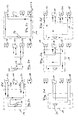
- Figuren 2a)-f):
- verschiedene Systemzustände
- FIG. 1:
- a flow diagram of a hot water and heating system according to the invention
- FIGS. 2a) -f):
- different system states
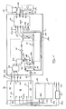
Das Bezugszeichen 10 charakterisiert eine Gruppe von Sonnenkollektoren, das Bezugszeichen 12 eine Gruppe von Luftwärmetauschern. Beide werden von Glykol als Wärmeträger-Medium durchströmt, wobei Zu- und Ableitungen 10a, 10b für die Sonnenkollektoren 10 beziehungsweise 12a, 12b für die Luftwärmetauscher 12 an ein Mehrwegeventil 14 angeschlossen sind.The
Vom Mehrwegeventil 14 verläuft eine Leitung 16a zu einem Plattenwärmetauscher 18; die korrespondiere Rückführleitung ist mit 16b gekennzeichnet. Weiters verläuft vom Mehrwegeventil 14 eine Leitung 20a zu einem Plattenwärmetauscher 22. Die korrespondierende Rückführleitung 20b mündet in das Ventil 14 ein.From the
Mit dem Mehrwegeventil 14 sind ferner eine Druck- und eine Saugseite 24a, 24b einer Pumpe verbunden, um den Glykolstrom durch die Leitungen 10a, 10b, 12a, 12b, 16a, 16b, 20a, 20b fördern zu können, die gemeinsam den Glykolkreislauf (= Solekreislauf) bilden.With the
Der Plattenwärmetauscher 22 ist Bestandteil einer Wärmepumpe, deren zughöriger Kompressor mit 26, deren zweistufiger Kondensator mit 28 und deren Entspannungsventil mit 30 gekennzeichnet ist. Die Strömungswege innerhalb der Wärmepumpe sind durch Pfeile gekennzeichnet.The
Die erste Stufe 28a des Kondensators 28 wird von einem Plattenwärmetauscher gebildet, ebenso wie die zweite Stufe 28b. Beide werden im Gegenstrom von Wasser durchströmt, welches über eine Leitung 32 aus einem Pufferspeicher 34 gepumpt wird (Pumpe 36). Innerhalb des Kondensatorteils 28a können Teilströme des erwärmten Wassers weggeführt werden, was durch die Bezugszeichen 32a, 32b symbolisiert ist, wobei diese Leitungen in ein Mischventil 38 einmünden. Im Mischventil 38 können die über die Leitungen 32a, 32b mit unterschiedlicher Temperatur einlaufenden Wasserströme direkt oder nach Vermischung über Ablaufleitungen 40a, 40b, 40c, je nach Temperatur, in unterschiedliche Zonen des Pufferspeichers 34 eingespeist werden.The first stage 28a of the
Das Volumen des Pufferspeichers 34 ist durch Zwischenböden 42, 44 in Zonen aufgeteilt, die strömungstechnisch (randseitig) verbunden sind. Entsprechend befindet sich oben, im Raum 46, das Wasser mit der höchsten Temperatur, beispielsweise 60°-90°, darunter (zwischen 42 und 44) ein Speicherraum für Wasser mittlerer Temperatur von beispielsweise 30°-60° (Raum 48) und schließlich unterhalb des Zwischenbodens 44 ein Kaltwasserraum 50.The volume of the
Vom Raum 46 verläuft eine Warmwasserleitung 52a zu einem im Gegenstrom arbeitenden Spiralwärmetauscher 54. Die Rückleitung in den Raum 50 des Plattenspeichers 34 trägt die Ziffer 52b. Die im Wärmetauscher 54 durchgeführten Frischwasserströme sind mit 56a, 56b gekennzeichnet.From the
Aus dem oberen Teil des Raums 48 verläuft eine Leitung 58a zu einem ersten Heizkreis 60, an den nicht dargestellte Radiatoren angeschlossen sind. Die Rückführleitung trägt das Bezugszeichen 58b.From the upper part of the
Ein zweiter Heizkreislauf 62 für eine Niedrigtemperatur-Fußbodenheizung ist mit einer Zulaufleitung 64a und einer Rücklaufleitung 64b gekoppelt. Die Zuführleitung verläuft vom mittleren Teil des Raumes 48 im Pufferspeicher 34, die Rückführleitung 46b mündet in den unteren Abschnitt des Raums 48.A second low temperature
Der Strömungsweg des Wärmeträger-Mediums (Glykol) ist durch Pfeile gekennzeichnet. An den Ein- und Ausgängen der zugehörigen Systembauteile sind beispielhafte Temperaturen für das Glykol angegeben. Bei dieser Fahrweise bleiben die Sonnenkollektoren 10 ebenso unbenutzt wie der autarke Wärmetauscher 18. Der Glykolstrom wird mit Hilfe der Pumpe 24 ausschließlich zwischen Luftwärmetauscher 12 und Verdampfer 22 geführt.The flow path of the heat transfer medium (glycol) is indicated by arrows. Exemplary temperatures for the glycol are given at the inputs and outputs of the associated system components. In this procedure, the
Auf der anderen Seite des Verdampfers 22 verdampft das Kältemittel; Dampf wird anschließend durch den Kompressor 26 geführt und dabei aufgewärmt. Es gelangt anschließend in den Kondensator 28, wird dort immer noch bei hohem Druck abgekühlt und schließlich kondensiert, bevor es durch das Entspannungsventil 30 geführt wird. Parallel wird Wasser im Kondensator 28 (den Plattenwärmetauschern 28a, 28b) im Gegenstrom erwärmt und über die Leitungen 32a und/oder 32b beziehungsweise 40a, b, c in den Pufferspeicher 34 geführt.On the other side of the
Im Winter kann es passieren, dass der Luftwärmetauscher 12 vereist. Für diesen Fall bietet das System die Möglichkeit der umgekehrten Fahrweise. Aus dem Pufferspeicher 34 wird Wasser über den Wärmetauscher 18 geleitet, um die Sole (Glykol) zu erwärmen, welches anschließend durch den Luftwärmetauscher 12 geführt wird und diesen abtaut. Erneut wird das Mehrwegeventil 14 zur Einstellung des gewünschten Strömungsweges genutzt (
Diese Schaltung lässt sich analog im Sommer nutzen, um eine Überhitzung des Sonnenkollektors 10 zu vermeiden, wenn beispielsweise keine weitere Energiezufuhr in den Wasserspeicher benötigt wird. In diesem Betriebs-, zustand wird der Solestrom mittels des Luftwärmetauschers 12 gekühlt.This circuit can be used analogously in the summer to avoid overheating of the
Der Solestrom kann dazu auch am Verdampfer 22 vorbei direkt vom Sonnenkollektor 10 zum Luftwärmetauscher 12 und zurück zirkuliert werden. Dazu wird eine separate Pumpe aktiviert.The brine flow can also be circulated by the
In
Die in der Anmeldung beschriebenen Merkmale können einzeln oder in unterschiedlichen Kombinationen auch unter Ausschluss einzelner Merkmale, für die Erfindung angewendet werden.The features described in the application can be used individually or in different combinations, even excluding individual features, for the invention.
Claims (15)
Priority Applications (1)
| Application Number | Priority Date | Filing Date | Title |
|---|---|---|---|
| EP10008583A EP2345850A1 (en) | 2007-02-26 | 2008-01-30 | Heat pump |
Applications Claiming Priority (1)
| Application Number | Priority Date | Filing Date | Title |
|---|---|---|---|
| DE102007009196A DE102007009196B4 (en) | 2007-02-26 | 2007-02-26 | Hot water and heating system operating on the basis of renewable energy sources |
Related Child Applications (1)
| Application Number | Title | Priority Date | Filing Date |
|---|---|---|---|
| EP10008583.6 Division-Into | 2010-08-17 |
Publications (3)
| Publication Number | Publication Date |
|---|---|
| EP1962024A2 true EP1962024A2 (en) | 2008-08-27 |
| EP1962024A3 EP1962024A3 (en) | 2009-06-17 |
| EP1962024B1 EP1962024B1 (en) | 2010-12-22 |
Family
ID=39591269
Family Applications (2)
| Application Number | Title | Priority Date | Filing Date |
|---|---|---|---|
| EP08001685A Not-in-force EP1962024B1 (en) | 2007-02-26 | 2008-01-30 | Hot water heating sytem and central heating system using renewable energy sources |
| EP10008583A Withdrawn EP2345850A1 (en) | 2007-02-26 | 2008-01-30 | Heat pump |
Family Applications After (1)
| Application Number | Title | Priority Date | Filing Date |
|---|---|---|---|
| EP10008583A Withdrawn EP2345850A1 (en) | 2007-02-26 | 2008-01-30 | Heat pump |
Country Status (7)
| Country | Link |
|---|---|
| US (1) | US20080203179A1 (en) |
| EP (2) | EP1962024B1 (en) |
| AT (1) | ATE492776T1 (en) |
| AU (1) | AU2008200743B2 (en) |
| CA (1) | CA2621084C (en) |
| DE (2) | DE102007009196B4 (en) |
| DK (1) | DK1962024T3 (en) |
Cited By (14)
| Publication number | Priority date | Publication date | Assignee | Title |
|---|---|---|---|---|
| WO2010102640A1 (en) * | 2009-03-09 | 2010-09-16 | Sol Energy Hellas S.A. | Hybrid thermal energy systems and applications thereof |
| EP2352952A1 (en) * | 2008-10-20 | 2011-08-10 | Török, Vilmos | Heat pump apparatus |
| CN102287862A (en) * | 2011-07-11 | 2011-12-21 | 北京圣兆科技开发有限公司 | Novel heating system |
| CN103196171A (en) * | 2013-04-03 | 2013-07-10 | 江南大学 | Combined heating strategy of multi-heat-source hot-water system |
| CN103443549A (en) * | 2011-03-30 | 2013-12-11 | 特灵国际有限公司 | Systems and methods for controlling a hybrid heating system |
| WO2014076087A1 (en) * | 2012-11-13 | 2014-05-22 | Bs2 Ag | Valve for changing over the heat flows of a heat pump, taking into account the flow direction reversal in a heat exchanger connected during heating operation to the source side of the heat pump |
| WO2014150886A1 (en) * | 2013-03-15 | 2014-09-25 | Johnson Controls Technology Company | Subcooling system with thermal storage |
| EP2864710A4 (en) * | 2012-06-12 | 2016-02-17 | Endless Solar Corp Ltd | A solar energy system |
| EP2859280A4 (en) * | 2012-06-12 | 2016-02-17 | Endless Solar Corp Ltd | A solar energy system |
| CN105783100A (en) * | 2016-04-29 | 2016-07-20 | 安徽康特姆新能源工程有限公司 | Air source and sewage source combined heat pump hot-water system for concentrated bathing place and control method |
| CN107576076A (en) * | 2017-09-08 | 2018-01-12 | 真木农业设备(安徽)有限公司 | A kind of solar energy temperature control system and its application method |
| CN107642910A (en) * | 2017-09-08 | 2018-01-30 | 真木农业设备(安徽)有限公司 | A kind of indoor solar takes heat structure and its application method |
| CN108302667A (en) * | 2017-09-08 | 2018-07-20 | 真木农业设备(安徽)有限公司 | A kind of indoor solar temperature control system and its application method |
| CN114909703A (en) * | 2022-04-02 | 2022-08-16 | 大连理工大学 | Season-crossing cold and hot dual-energy-storage-source system of solar PVT heat pump |
Families Citing this family (10)
| Publication number | Priority date | Publication date | Assignee | Title |
|---|---|---|---|---|
| DE102011014531B4 (en) * | 2011-03-18 | 2018-12-13 | Bodo M. Wolf | Method for integrating electric heat pumps into the hot water and heating heat supply |
| CN102519077A (en) * | 2011-12-18 | 2012-06-27 | 杨艺明 | Method for supplying heat by aid of portable tea-urn |
| CN103453581B (en) * | 2013-09-06 | 2016-04-13 | 程宁 | For the heat supply conversion control device of solar heating heating system |
| US10047985B2 (en) | 2014-03-10 | 2018-08-14 | Johnson Controls Technology Company | Subcooling system with thermal energy storage |
| KR101469459B1 (en) * | 2014-07-01 | 2014-12-08 | 주식회사 신진에너텍 | Heat pump system using complex heat sources and its controlling process |
| CN105180246B (en) * | 2015-10-21 | 2018-01-02 | 珠海格力电器股份有限公司 | A kind of waste heat source heat pump heating control system and control method |
| CN105674371A (en) * | 2015-12-30 | 2016-06-15 | 中铁二十一局集团第二工程有限公司 | Solar heating system, multi-heat-source heating system and multi-heat-source heat supply method |
| EP3267119A1 (en) * | 2016-07-07 | 2018-01-10 | E.ON Sverige AB | Combined heating and cooling system |
| CN106402981A (en) * | 2016-08-30 | 2017-02-15 | 洛阳双瑞特种装备有限公司 | Large-temperature-difference waste heat recovery heat supply unit for electric drive heat pumps |
| DE102020117660A1 (en) * | 2019-12-20 | 2021-06-24 | Stiebel Eltron Gmbh & Co. Kg | Mobile system set for hot water generation, heating and / or cooling |
Citations (4)
| Publication number | Priority date | Publication date | Assignee | Title |
|---|---|---|---|---|
| EP0041272A1 (en) * | 1980-06-04 | 1981-12-09 | André Alain Picchiottino | Installation for room heating and for the production of domestic hot water |
| FR2505990A1 (en) * | 1981-05-14 | 1982-11-19 | Calories Geothermiques Solaire | Local heating system using solar, geothermal and heat pump sources - has heating water storage and domestic hot water storage heated by coil heat exchangers supplied with heated fluid |
| US4598694A (en) * | 1985-01-08 | 1986-07-08 | Cromer Charles J | Water heater partition and method |
| DE10300427A1 (en) * | 2003-01-09 | 2004-07-22 | Consolar Energiespeicher- Und Regelungssysteme Gmbh | Method for combining heat from solar energy system with heat pump has solar panel output selectively directed to hot water tank or heat pump evaporator |
Family Cites Families (56)
| Publication number | Priority date | Publication date | Assignee | Title |
|---|---|---|---|---|
| US1969187A (en) * | 1932-02-19 | 1934-08-07 | Clifton E Schutt | Heat balancing system |
| US2030350A (en) * | 1933-04-10 | 1936-02-11 | Carl G Fisher | Solar operated refrigerating system |
| US2241060A (en) * | 1939-08-24 | 1941-05-06 | Gen Electric | Heat pump system |
| US3411571A (en) * | 1966-11-07 | 1968-11-19 | Hooker Chemical Corp | Heat storage exchange apparatus and method therefor |
| DE2224242A1 (en) * | 1972-05-18 | 1973-11-29 | Ctc Gmbh | SYSTEM FOR TEMPERATURE CONTROL, IN PARTICULAR FOR COOLING ROOMS |
| US4007776A (en) * | 1974-12-23 | 1977-02-15 | Universal Oil Products Company | Heating and cooling system utilizing solar energy |
| GB1532542A (en) * | 1975-01-14 | 1978-11-15 | Awalt T | Hot or cold storage system |
| US3996759A (en) * | 1975-11-03 | 1976-12-14 | Milton Meckler | Environment assisted hydronic heat pump system |
| US4004573A (en) * | 1975-12-23 | 1977-01-25 | Battelle Development Corporation | Process and apparatus for solar energy collection and retrieval |
| US4128124A (en) * | 1976-02-17 | 1978-12-05 | Worthington Mark N | Multi-mode solar heating and cooling system |
| US4111259A (en) * | 1976-03-12 | 1978-09-05 | Ecosol, Ltd. | Energy conservation system |
| US4030312A (en) * | 1976-04-07 | 1977-06-21 | Shantzer-Wallin Corporation | Heat pumps with solar heat source |
| US4049407A (en) * | 1976-08-18 | 1977-09-20 | Bottum Edward W | Solar assisted heat pump system |
| US4123003A (en) * | 1976-09-03 | 1978-10-31 | Theodore Winston | Solar energy collection panels and energy recovery systems |
| US4133183A (en) * | 1976-12-29 | 1979-01-09 | Borg-Warner Corporation | Solar powered absorption refrigeration system |
| DE2720319C2 (en) * | 1977-05-06 | 1984-08-09 | Max Planck Gesellschaft zur Förderung der Wissenschaften e.V., 3400 Göttingen | Heat collector system |
| US4256475A (en) * | 1977-07-22 | 1981-03-17 | Carrier Corporation | Heat transfer and storage system |
| US4165036A (en) * | 1977-08-29 | 1979-08-21 | Milton Meckler | Multi source heat pump air conditioning system |
| US4180209A (en) * | 1977-09-28 | 1979-12-25 | Owens-Illinois, Inc. | Solar energy operated system and method |
| US4169554A (en) * | 1977-10-20 | 1979-10-02 | Camp Eldon D | Solar energy system with heat pump assistance |
| US4173994A (en) * | 1977-12-30 | 1979-11-13 | Hiser Leland L | Solar energy heating and cooling apparatus and method |
| US4190199A (en) * | 1978-01-06 | 1980-02-26 | Lennox Industries Inc. | Combination heating system including a conventional furnace, heat pump and solar energy subsystem |
| US4220138A (en) * | 1978-01-24 | 1980-09-02 | Bottum Edward W | Refrigerant charged solar heating structure and system |
| US4269263A (en) * | 1978-03-02 | 1981-05-26 | Osaka Gas Kabushiki Kaisha | Cooling and heating system utilizing solar heat |
| US4187688A (en) * | 1978-10-10 | 1980-02-12 | Owens-Illinois, Inc. | Solar powered intermittent cycle heat pump |
| US4223535A (en) * | 1978-12-22 | 1980-09-23 | Kumm Emerson L | Absorption solar powered air conditioning system with storage capacity |
| US4226752A (en) * | 1979-03-28 | 1980-10-07 | Scm Corporation | Emulsion process for polymer particles |
| US4295518A (en) * | 1979-06-01 | 1981-10-20 | United Technologies Corporation | Combined air cycle heat pump and refrigeration system |
| US4296729A (en) * | 1980-02-04 | 1981-10-27 | Suntime, Inc. | Solar hot water heating system |
| US4308042A (en) * | 1980-04-11 | 1981-12-29 | Atlantic Richfield Company | Heat pump with freeze-up prevention |
| US4336692A (en) * | 1980-04-16 | 1982-06-29 | Atlantic Richfield Company | Dual source heat pump |
| FR2485169B1 (en) * | 1980-06-20 | 1986-01-03 | Electricite De France | IMPROVEMENTS ON HOT WATER SUPPLY INSTALLATIONS INCLUDING A THERMODYNAMIC CIRCUIT |
| US4339930A (en) * | 1980-07-03 | 1982-07-20 | The United States Of America As Represented By The Secretary Of The Navy | Control system for solar-assisted heat pump system |
| US4444249A (en) * | 1981-08-20 | 1984-04-24 | Mcdonnell Douglas Corporation | Three-way heat pipe |
| JPS58133542A (en) * | 1982-02-03 | 1983-08-09 | Hitachi Ltd | Heat pump type air conditioner |
| JPS5946465A (en) * | 1982-09-10 | 1984-03-15 | 三菱電機株式会社 | Air-conditioning hot-water supply device |
| US4527618A (en) * | 1982-09-29 | 1985-07-09 | Solar Decisions, Inc. | Solar energy storage and distribution system with heat pump assist |
| US4787444A (en) * | 1983-12-19 | 1988-11-29 | Countryman James H | Heating and cooling system |
| US4979374A (en) * | 1990-03-01 | 1990-12-25 | Kabakov Vladimir I | Geothermal heat- and water supply plant |
| US5269153A (en) * | 1991-05-22 | 1993-12-14 | Artesian Building Systems, Inc. | Apparatus for controlling space heating and/or space cooling and water heating |
| US5320166A (en) * | 1993-01-06 | 1994-06-14 | Consolidated Natural Gas Service Company, Inc. | Heat pump system with refrigerant isolation and heat storage |
| US5941238A (en) * | 1997-02-25 | 1999-08-24 | Ada Tracy | Heat storage vessels for use with heat pumps and solar panels |
| KR100289751B1 (en) * | 1998-04-15 | 2001-05-15 | 진금수 | Heat pump type air conditioner |
| US6223433B1 (en) * | 1998-11-24 | 2001-05-01 | Calsonic N.A. Inc. | Dual-fluid heat-exchanging system with extruded thermal-transfer core and method of fabrication thereof |
| JP2000304368A (en) * | 1999-04-19 | 2000-11-02 | Daikin Ind Ltd | Air-conditioner |
| KR100343808B1 (en) * | 1999-12-30 | 2002-07-20 | 진금수 | Heat pump type air conditioner |
| US6539738B2 (en) * | 2000-06-08 | 2003-04-01 | University Of Puerto Rico | Compact solar-powered air conditioning systems |
| CN1120339C (en) * | 2000-08-18 | 2003-09-03 | 徐生恒 | Geothermal liquid cold and hot source system |
| DE10118572B4 (en) * | 2001-04-06 | 2006-08-03 | Harry Jentzsch | Heat supply system |
| JP4378900B2 (en) * | 2001-08-03 | 2009-12-09 | 株式会社デンソー | Heat pump type water heater |
| US7913684B2 (en) * | 2002-02-27 | 2011-03-29 | Barry Lynn Butler | Solar heat transfer system (HTPL), high temperature pressurized loop |
| AT412911B (en) * | 2002-03-07 | 2005-08-25 | Thermo System Kaelte Klima Und | DEVICE FOR HEATING A HEAT CARRIER |
| DE10312825B4 (en) * | 2003-03-22 | 2006-01-12 | Danfoss A/S | Method for setting a plurality of parallel-connected heat exchangers |
| JP4497527B2 (en) * | 2004-05-31 | 2010-07-07 | 日立アプライアンス株式会社 | Refrigeration equipment |
| DE202005013499U1 (en) * | 2005-08-26 | 2005-10-27 | Wenzel, Bernhard | Cooling medium circuit for a heat pump has compressor evaporator and expansion valve with two condensers operating at different temperatures |
| JP4592616B2 (en) * | 2006-02-27 | 2010-12-01 | 三洋電機株式会社 | Refrigeration cycle equipment |
-
2007
- 2007-02-26 DE DE102007009196A patent/DE102007009196B4/en not_active Expired - Fee Related
-
2008
- 2008-01-30 EP EP08001685A patent/EP1962024B1/en not_active Not-in-force
- 2008-01-30 DK DK08001685.0T patent/DK1962024T3/en active
- 2008-01-30 EP EP10008583A patent/EP2345850A1/en not_active Withdrawn
- 2008-01-30 AT AT08001685T patent/ATE492776T1/en active
- 2008-01-30 DE DE502008002038T patent/DE502008002038D1/en active Active
- 2008-02-14 CA CA2621084A patent/CA2621084C/en not_active Expired - Fee Related
- 2008-02-15 AU AU2008200743A patent/AU2008200743B2/en not_active Ceased
- 2008-02-18 US US12/032,803 patent/US20080203179A1/en not_active Abandoned
Patent Citations (4)
| Publication number | Priority date | Publication date | Assignee | Title |
|---|---|---|---|---|
| EP0041272A1 (en) * | 1980-06-04 | 1981-12-09 | André Alain Picchiottino | Installation for room heating and for the production of domestic hot water |
| FR2505990A1 (en) * | 1981-05-14 | 1982-11-19 | Calories Geothermiques Solaire | Local heating system using solar, geothermal and heat pump sources - has heating water storage and domestic hot water storage heated by coil heat exchangers supplied with heated fluid |
| US4598694A (en) * | 1985-01-08 | 1986-07-08 | Cromer Charles J | Water heater partition and method |
| DE10300427A1 (en) * | 2003-01-09 | 2004-07-22 | Consolar Energiespeicher- Und Regelungssysteme Gmbh | Method for combining heat from solar energy system with heat pump has solar panel output selectively directed to hot water tank or heat pump evaporator |
Cited By (21)
| Publication number | Priority date | Publication date | Assignee | Title |
|---|---|---|---|---|
| EP2352952A4 (en) * | 2008-10-20 | 2012-03-21 | Vilmos Toeroek | Heat pump apparatus |
| EP2352952A1 (en) * | 2008-10-20 | 2011-08-10 | Török, Vilmos | Heat pump apparatus |
| WO2010102640A1 (en) * | 2009-03-09 | 2010-09-16 | Sol Energy Hellas S.A. | Hybrid thermal energy systems and applications thereof |
| CN103443549A (en) * | 2011-03-30 | 2013-12-11 | 特灵国际有限公司 | Systems and methods for controlling a hybrid heating system |
| CN103443549B (en) * | 2011-03-30 | 2017-05-31 | 特灵国际有限公司 | System and method for controlling Hybrid Heating system |
| CN102287862B (en) * | 2011-07-11 | 2013-05-08 | 北京圣兆科技开发有限公司 | Novel heating system |
| CN102287862A (en) * | 2011-07-11 | 2011-12-21 | 北京圣兆科技开发有限公司 | Novel heating system |
| EP2864710A4 (en) * | 2012-06-12 | 2016-02-17 | Endless Solar Corp Ltd | A solar energy system |
| EP2859280A4 (en) * | 2012-06-12 | 2016-02-17 | Endless Solar Corp Ltd | A solar energy system |
| US10598392B2 (en) | 2012-06-12 | 2020-03-24 | Endless Solar Corporation Ltd | Solar energy system |
| US10094577B2 (en) | 2012-06-12 | 2018-10-09 | Endless Solar Corporation Ltd | Solar energy system |
| WO2014076087A1 (en) * | 2012-11-13 | 2014-05-22 | Bs2 Ag | Valve for changing over the heat flows of a heat pump, taking into account the flow direction reversal in a heat exchanger connected during heating operation to the source side of the heat pump |
| WO2014150886A1 (en) * | 2013-03-15 | 2014-09-25 | Johnson Controls Technology Company | Subcooling system with thermal storage |
| CN103196171A (en) * | 2013-04-03 | 2013-07-10 | 江南大学 | Combined heating strategy of multi-heat-source hot-water system |
| CN103196171B (en) * | 2013-04-03 | 2016-02-24 | 江南大学 | A kind of combined heat strategy of Multiple-heat-sourcehot hot water system |
| CN105783100B (en) * | 2016-04-29 | 2018-10-02 | 安徽康特姆新能源工程股份有限公司 | Concentrate outdoor bathing place air-source and sewage source composite heat pump hot-water heating system and control method |
| CN105783100A (en) * | 2016-04-29 | 2016-07-20 | 安徽康特姆新能源工程有限公司 | Air source and sewage source combined heat pump hot-water system for concentrated bathing place and control method |
| CN107576076A (en) * | 2017-09-08 | 2018-01-12 | 真木农业设备(安徽)有限公司 | A kind of solar energy temperature control system and its application method |
| CN107642910A (en) * | 2017-09-08 | 2018-01-30 | 真木农业设备(安徽)有限公司 | A kind of indoor solar takes heat structure and its application method |
| CN108302667A (en) * | 2017-09-08 | 2018-07-20 | 真木农业设备(安徽)有限公司 | A kind of indoor solar temperature control system and its application method |
| CN114909703A (en) * | 2022-04-02 | 2022-08-16 | 大连理工大学 | Season-crossing cold and hot dual-energy-storage-source system of solar PVT heat pump |
Also Published As
| Publication number | Publication date |
|---|---|
| CA2621084C (en) | 2012-12-18 |
| DE502008002038D1 (en) | 2011-02-03 |
| US20080203179A1 (en) | 2008-08-28 |
| EP1962024B1 (en) | 2010-12-22 |
| EP1962024A3 (en) | 2009-06-17 |
| EP2345850A1 (en) | 2011-07-20 |
| DE102007009196A1 (en) | 2008-08-28 |
| AU2008200743B2 (en) | 2010-07-08 |
| ATE492776T1 (en) | 2011-01-15 |
| CA2621084A1 (en) | 2008-08-26 |
| DK1962024T3 (en) | 2011-01-31 |
| AU2008200743A1 (en) | 2008-09-11 |
| DE102007009196B4 (en) | 2010-07-01 |
Similar Documents
| Publication | Publication Date | Title |
|---|---|---|
| EP1962024B1 (en) | Hot water heating sytem and central heating system using renewable energy sources | |
| AT502029B1 (en) | DEVICE FOR VENTILATION AND HEATING OF BUILDINGS | |
| DE10300427B4 (en) | Solar system with heat pump | |
| AT504935B1 (en) | MORE WAYS VALVE | |
| DE102017206180A1 (en) | Heat pump system for a vehicle | |
| DE2759181A1 (en) | METHOD FOR TEMPERATURE TEMPERATURE AND BUILDING TO BE HEATED BY THIS METHOD | |
| DE3209761A1 (en) | HEAT PUMP SYSTEM | |
| WO2009049612A2 (en) | Heat accumulator for storing thermal energy and method for shifting thermal energy in a heat accumulator | |
| EP1616133B1 (en) | Combined fluid-air evaporator and novel switching concept for a heat pump in a ventilating apparatus | |
| EP3447403B1 (en) | Operating method for heat generation installations, air/liquid heat exchanger unit and heat generation installation | |
| EP3835666B1 (en) | Building system for air conditioning and heat supply | |
| WO2012159763A2 (en) | Combined photovoltaic and solar thermal system | |
| EP2458304A2 (en) | Heat pump assembly comprising a heat pump and method for operating such a heat pump assembly | |
| EP2063193A1 (en) | Method of air conditioning a building | |
| DE102013218278A1 (en) | Plate-shaped heat exchanger element for an ice storage | |
| DE102010056370A1 (en) | Device for increasing efficiency of heat pump system for use during industrial water treatment, has condenser connected with valve such that industrial water is flowed, and heat carrier circuit that is closed between condenser and tanks | |
| DE2608873C3 (en) | Method and device for heating rooms by means of a heat pump process | |
| AT12588U1 (en) | DEVICE FOR PROVIDING THERMAL ENERGY | |
| DE102011002214A1 (en) | Hydraulic distributor for more than two temperatures and more than one consumer and / or heat generator | |
| DE3019475A1 (en) | Combined solar heating system and heat pump - circulates hot air through evaporator coils circulating two heat exchange fluids | |
| AT507074B1 (en) | METHOD FOR OPERATING A DEVICE FOR HEATING A BUILDING AND PREPARING HOT WATER | |
| DE102007062342B4 (en) | Method and arrangement for increasing the temperature level in the circuit of solar thermal systems or combined heat and power plants | |
| DE202023001213U1 (en) | Modular geothermal energy plant | |
| DE19861020C1 (en) | Ventilation arrangement for buildings extracts heat from outlet air directed out of building or from air fed into building using heat pump with coolant or water heat transfer device | |
| EP3460340B1 (en) | Method for providing heat, heat recovery system and heat provision unit |
Legal Events
| Date | Code | Title | Description |
|---|---|---|---|
| PUAI | Public reference made under article 153(3) epc to a published international application that has entered the european phase |
Free format text: ORIGINAL CODE: 0009012 |
|
| AK | Designated contracting states |
Kind code of ref document: A2 Designated state(s): AT BE BG CH CY CZ DE DK EE ES FI FR GB GR HR HU IE IS IT LI LT LU LV MC MT NL NO PL PT RO SE SI SK TR |
|
| AX | Request for extension of the european patent |
Extension state: AL BA MK RS |
|
| RAP1 | Party data changed (applicant data changed or rights of an application transferred) |
Owner name: KIOTO CLEAR ENERGY AG |
|
| PUAL | Search report despatched |
Free format text: ORIGINAL CODE: 0009013 |
|
| AK | Designated contracting states |
Kind code of ref document: A3 Designated state(s): AT BE BG CH CY CZ DE DK EE ES FI FR GB GR HR HU IE IS IT LI LT LU LV MC MT NL NO PL PT RO SE SI SK TR |
|
| AX | Request for extension of the european patent |
Extension state: AL BA MK RS |
|
| RIC1 | Information provided on ipc code assigned before grant |
Ipc: F24D 11/02 20060101AFI20080718BHEP Ipc: F28D 20/00 20060101ALN20090514BHEP Ipc: F24D 19/10 20060101ALI20090514BHEP Ipc: F24D 3/08 20060101ALI20090514BHEP Ipc: F24D 11/00 20060101ALI20090514BHEP |
|
| 17P | Request for examination filed |
Effective date: 20090808 |
|
| 17Q | First examination report despatched |
Effective date: 20091023 |
|
| AKX | Designation fees paid |
Designated state(s): AT BE BG CH CY CZ DE DK EE ES FI FR GB GR HR HU IE IS IT LI LT LU LV MC MT NL NO PL PT RO SE SI SK TR |
|
| GRAP | Despatch of communication of intention to grant a patent |
Free format text: ORIGINAL CODE: EPIDOSNIGR1 |
|
| RIN1 | Information on inventor provided before grant (corrected) |
Inventor name: STRICKER, ERWIN Inventor name: EUSCH, INGRAM Inventor name: BERGER, ERWIN Inventor name: KREINER, THOMAS Inventor name: PAVICSICS, REINHARD |
|
| GRAS | Grant fee paid |
Free format text: ORIGINAL CODE: EPIDOSNIGR3 |
|
| GRAA | (expected) grant |
Free format text: ORIGINAL CODE: 0009210 |
|
| AK | Designated contracting states |
Kind code of ref document: B1 Designated state(s): AT BE BG CH CY CZ DE DK EE ES FI FR GB GR HR HU IE IS IT LI LT LU LV MC MT NL NO PL PT RO SE SI SK TR |
|
| REG | Reference to a national code |
Ref country code: GB Ref legal event code: FG4D Free format text: NOT ENGLISH |
|
| REG | Reference to a national code |
Ref country code: CH Ref legal event code: EP |
|
| REG | Reference to a national code |
Ref country code: CH Ref legal event code: NV Representative=s name: HANS RUDOLF GACHNANG PATENTANWALT |
|
| REG | Reference to a national code |
Ref country code: IE Ref legal event code: FG4D |
|
| REG | Reference to a national code |
Ref country code: DK Ref legal event code: T3 |
|
| REF | Corresponds to: |
Ref document number: 502008002038 Country of ref document: DE Date of ref document: 20110203 Kind code of ref document: P |
|
| REG | Reference to a national code |
Ref country code: DE Ref legal event code: R096 Ref document number: 502008002038 Country of ref document: DE Effective date: 20110203 |
|
| REG | Reference to a national code |
Ref country code: SE Ref legal event code: TRGR |
|
| PGFP | Annual fee paid to national office [announced via postgrant information from national office to epo] |
Ref country code: LU Payment date: 20110124 Year of fee payment: 4 |
|
| REG | Reference to a national code |
Ref country code: NL Ref legal event code: T3 |
|
| REG | Reference to a national code |
Ref country code: NO Ref legal event code: T2 Effective date: 20101222 |
|
| PG25 | Lapsed in a contracting state [announced via postgrant information from national office to epo] |
Ref country code: LT Free format text: LAPSE BECAUSE OF FAILURE TO SUBMIT A TRANSLATION OF THE DESCRIPTION OR TO PAY THE FEE WITHIN THE PRESCRIBED TIME-LIMIT Effective date: 20101222 |
|
| LTIE | Lt: invalidation of european patent or patent extension |
Effective date: 20101222 |
|
| PG25 | Lapsed in a contracting state [announced via postgrant information from national office to epo] |
Ref country code: HR Free format text: LAPSE BECAUSE OF FAILURE TO SUBMIT A TRANSLATION OF THE DESCRIPTION OR TO PAY THE FEE WITHIN THE PRESCRIBED TIME-LIMIT Effective date: 20101222 Ref country code: CY Free format text: LAPSE BECAUSE OF FAILURE TO SUBMIT A TRANSLATION OF THE DESCRIPTION OR TO PAY THE FEE WITHIN THE PRESCRIBED TIME-LIMIT Effective date: 20101222 Ref country code: LV Free format text: LAPSE BECAUSE OF FAILURE TO SUBMIT A TRANSLATION OF THE DESCRIPTION OR TO PAY THE FEE WITHIN THE PRESCRIBED TIME-LIMIT Effective date: 20101222 Ref country code: SI Free format text: LAPSE BECAUSE OF FAILURE TO SUBMIT A TRANSLATION OF THE DESCRIPTION OR TO PAY THE FEE WITHIN THE PRESCRIBED TIME-LIMIT Effective date: 20101222 Ref country code: BG Free format text: LAPSE BECAUSE OF FAILURE TO SUBMIT A TRANSLATION OF THE DESCRIPTION OR TO PAY THE FEE WITHIN THE PRESCRIBED TIME-LIMIT Effective date: 20110322 Ref country code: FI Free format text: LAPSE BECAUSE OF FAILURE TO SUBMIT A TRANSLATION OF THE DESCRIPTION OR TO PAY THE FEE WITHIN THE PRESCRIBED TIME-LIMIT Effective date: 20101222 |
|
| REG | Reference to a national code |
Ref country code: IE Ref legal event code: FD4D |
|
| PG25 | Lapsed in a contracting state [announced via postgrant information from national office to epo] |
Ref country code: PT Free format text: LAPSE BECAUSE OF FAILURE TO SUBMIT A TRANSLATION OF THE DESCRIPTION OR TO PAY THE FEE WITHIN THE PRESCRIBED TIME-LIMIT Effective date: 20110422 Ref country code: CZ Free format text: LAPSE BECAUSE OF FAILURE TO SUBMIT A TRANSLATION OF THE DESCRIPTION OR TO PAY THE FEE WITHIN THE PRESCRIBED TIME-LIMIT Effective date: 20101222 Ref country code: GR Free format text: LAPSE BECAUSE OF FAILURE TO SUBMIT A TRANSLATION OF THE DESCRIPTION OR TO PAY THE FEE WITHIN THE PRESCRIBED TIME-LIMIT Effective date: 20110323 Ref country code: ES Free format text: LAPSE BECAUSE OF FAILURE TO SUBMIT A TRANSLATION OF THE DESCRIPTION OR TO PAY THE FEE WITHIN THE PRESCRIBED TIME-LIMIT Effective date: 20110402 Ref country code: EE Free format text: LAPSE BECAUSE OF FAILURE TO SUBMIT A TRANSLATION OF THE DESCRIPTION OR TO PAY THE FEE WITHIN THE PRESCRIBED TIME-LIMIT Effective date: 20101222 Ref country code: IS Free format text: LAPSE BECAUSE OF FAILURE TO SUBMIT A TRANSLATION OF THE DESCRIPTION OR TO PAY THE FEE WITHIN THE PRESCRIBED TIME-LIMIT Effective date: 20110422 |
|
| PG25 | Lapsed in a contracting state [announced via postgrant information from national office to epo] |
Ref country code: RO Free format text: LAPSE BECAUSE OF FAILURE TO SUBMIT A TRANSLATION OF THE DESCRIPTION OR TO PAY THE FEE WITHIN THE PRESCRIBED TIME-LIMIT Effective date: 20101222 Ref country code: MC Free format text: LAPSE BECAUSE OF NON-PAYMENT OF DUE FEES Effective date: 20110131 Ref country code: SK Free format text: LAPSE BECAUSE OF FAILURE TO SUBMIT A TRANSLATION OF THE DESCRIPTION OR TO PAY THE FEE WITHIN THE PRESCRIBED TIME-LIMIT Effective date: 20101222 Ref country code: PL Free format text: LAPSE BECAUSE OF FAILURE TO SUBMIT A TRANSLATION OF THE DESCRIPTION OR TO PAY THE FEE WITHIN THE PRESCRIBED TIME-LIMIT Effective date: 20101222 |
|
| PLBI | Opposition filed |
Free format text: ORIGINAL CODE: 0009260 |
|
| 26 | Opposition filed |
Opponent name: VAILLANT GMBH Effective date: 20110913 |
|
| PLAX | Notice of opposition and request to file observation + time limit sent |
Free format text: ORIGINAL CODE: EPIDOSNOBS2 |
|
| PLAB | Opposition data, opponent's data or that of the opponent's representative modified |
Free format text: ORIGINAL CODE: 0009299OPPO |
|
| PG25 | Lapsed in a contracting state [announced via postgrant information from national office to epo] |
Ref country code: IE Free format text: LAPSE BECAUSE OF FAILURE TO SUBMIT A TRANSLATION OF THE DESCRIPTION OR TO PAY THE FEE WITHIN THE PRESCRIBED TIME-LIMIT Effective date: 20101222 |
|
| R26 | Opposition filed (corrected) |
Opponent name: VAILLANT GMBH Effective date: 20110913 |
|
| REG | Reference to a national code |
Ref country code: DE Ref legal event code: R026 Ref document number: 502008002038 Country of ref document: DE Effective date: 20110913 |
|
| PG25 | Lapsed in a contracting state [announced via postgrant information from national office to epo] |
Ref country code: MT Free format text: LAPSE BECAUSE OF FAILURE TO SUBMIT A TRANSLATION OF THE DESCRIPTION OR TO PAY THE FEE WITHIN THE PRESCRIBED TIME-LIMIT Effective date: 20101222 |
|
| PLBB | Reply of patent proprietor to notice(s) of opposition received |
Free format text: ORIGINAL CODE: EPIDOSNOBS3 |
|
| PGFP | Annual fee paid to national office [announced via postgrant information from national office to epo] |
Ref country code: TR Payment date: 20120120 Year of fee payment: 5 |
|
| PG25 | Lapsed in a contracting state [announced via postgrant information from national office to epo] |
Ref country code: HU Free format text: LAPSE BECAUSE OF FAILURE TO SUBMIT A TRANSLATION OF THE DESCRIPTION OR TO PAY THE FEE WITHIN THE PRESCRIBED TIME-LIMIT Effective date: 20101222 |
|
| REG | Reference to a national code |
Ref country code: CH Ref legal event code: NV Representative=s name: GACHNANG AG PATENTANWAELTE, CH |
|
| REG | Reference to a national code |
Ref country code: FR Ref legal event code: PLFP Year of fee payment: 8 |
|
| PGFP | Annual fee paid to national office [announced via postgrant information from national office to epo] |
Ref country code: NL Payment date: 20150122 Year of fee payment: 8 |
|
| PGFP | Annual fee paid to national office [announced via postgrant information from national office to epo] |
Ref country code: CH Payment date: 20150123 Year of fee payment: 8 Ref country code: DK Payment date: 20150126 Year of fee payment: 8 Ref country code: NO Payment date: 20150123 Year of fee payment: 8 Ref country code: IT Payment date: 20150123 Year of fee payment: 8 |
|
| PGFP | Annual fee paid to national office [announced via postgrant information from national office to epo] |
Ref country code: FR Payment date: 20150115 Year of fee payment: 8 Ref country code: GB Payment date: 20150123 Year of fee payment: 8 Ref country code: AT Payment date: 20150121 Year of fee payment: 8 Ref country code: SE Payment date: 20150123 Year of fee payment: 8 |
|
| PGFP | Annual fee paid to national office [announced via postgrant information from national office to epo] |
Ref country code: BE Payment date: 20150119 Year of fee payment: 8 |
|
| PG25 | Lapsed in a contracting state [announced via postgrant information from national office to epo] |
Ref country code: LU Free format text: LAPSE BECAUSE OF NON-PAYMENT OF DUE FEES Effective date: 20130130 |
|
| PG25 | Lapsed in a contracting state [announced via postgrant information from national office to epo] |
Ref country code: TR Free format text: LAPSE BECAUSE OF NON-PAYMENT OF DUE FEES Effective date: 20130130 |
|
| PLAY | Examination report in opposition despatched + time limit |
Free format text: ORIGINAL CODE: EPIDOSNORE2 |
|
| REG | Reference to a national code |
Ref country code: DE Ref legal event code: R082 Ref document number: 502008002038 Country of ref document: DE |
|
| PG25 | Lapsed in a contracting state [announced via postgrant information from national office to epo] |
Ref country code: BE Free format text: LAPSE BECAUSE OF NON-PAYMENT OF DUE FEES Effective date: 20160131 |
|
| REG | Reference to a national code |
Ref country code: NO Ref legal event code: MMEP Ref country code: DK Ref legal event code: EBP Effective date: 20160131 |
|
| REG | Reference to a national code |
Ref country code: CH Ref legal event code: PL |
|
| REG | Reference to a national code |
Ref country code: AT Ref legal event code: MM01 Ref document number: 492776 Country of ref document: AT Kind code of ref document: T Effective date: 20160130 |
|
| GBPC | Gb: european patent ceased through non-payment of renewal fee |
Effective date: 20160130 |
|
| REG | Reference to a national code |
Ref country code: NL Ref legal event code: MM Effective date: 20160201 |
|
| REG | Reference to a national code |
Ref country code: FR Ref legal event code: ST Effective date: 20160930 |
|
| PG25 | Lapsed in a contracting state [announced via postgrant information from national office to epo] |
Ref country code: CH Free format text: LAPSE BECAUSE OF NON-PAYMENT OF DUE FEES Effective date: 20160131 Ref country code: LI Free format text: LAPSE BECAUSE OF NON-PAYMENT OF DUE FEES Effective date: 20160131 Ref country code: GB Free format text: LAPSE BECAUSE OF NON-PAYMENT OF DUE FEES Effective date: 20160130 Ref country code: NO Free format text: LAPSE BECAUSE OF NON-PAYMENT OF DUE FEES Effective date: 20160131 |
|
| PGFP | Annual fee paid to national office [announced via postgrant information from national office to epo] |
Ref country code: DE Payment date: 20160627 Year of fee payment: 9 |
|
| PG25 | Lapsed in a contracting state [announced via postgrant information from national office to epo] |
Ref country code: AT Free format text: LAPSE BECAUSE OF NON-PAYMENT OF DUE FEES Effective date: 20160130 Ref country code: SE Free format text: LAPSE BECAUSE OF NON-PAYMENT OF DUE FEES Effective date: 20160131 Ref country code: NL Free format text: LAPSE BECAUSE OF NON-PAYMENT OF DUE FEES Effective date: 20160201 Ref country code: FR Free format text: LAPSE BECAUSE OF NON-PAYMENT OF DUE FEES Effective date: 20160201 |
|
| PG25 | Lapsed in a contracting state [announced via postgrant information from national office to epo] |
Ref country code: IT Free format text: LAPSE BECAUSE OF NON-PAYMENT OF DUE FEES Effective date: 20160130 |
|
| PG25 | Lapsed in a contracting state [announced via postgrant information from national office to epo] |
Ref country code: DK Free format text: LAPSE BECAUSE OF NON-PAYMENT OF DUE FEES Effective date: 20160131 |
|
| REG | Reference to a national code |
Ref country code: DE Ref legal event code: R119 Ref document number: 502008002038 Country of ref document: DE |
|
| REG | Reference to a national code |
Ref country code: DE Ref legal event code: R100 Ref document number: 502008002038 Country of ref document: DE |
|
| PLCK | Communication despatched that opposition was rejected |
Free format text: ORIGINAL CODE: EPIDOSNREJ1 |
|
| PG25 | Lapsed in a contracting state [announced via postgrant information from national office to epo] |
Ref country code: DE Free format text: LAPSE BECAUSE OF NON-PAYMENT OF DUE FEES Effective date: 20170801 |
|
| PLBN | Opposition rejected |
Free format text: ORIGINAL CODE: 0009273 |
|
| STAA | Information on the status of an ep patent application or granted ep patent |
Free format text: STATUS: OPPOSITION REJECTED |
|
| 27O | Opposition rejected |
Effective date: 20171019 |