EP1961999A2 - Control device and control method of transmission - Google Patents
Control device and control method of transmission Download PDFInfo
- Publication number
- EP1961999A2 EP1961999A2 EP08250567A EP08250567A EP1961999A2 EP 1961999 A2 EP1961999 A2 EP 1961999A2 EP 08250567 A EP08250567 A EP 08250567A EP 08250567 A EP08250567 A EP 08250567A EP 1961999 A2 EP1961999 A2 EP 1961999A2
- Authority
- EP
- European Patent Office
- Prior art keywords
- sleeve
- actuator
- gear
- rotation speed
- output shaft
- Prior art date
- Legal status (The legal status is an assumption and is not a legal conclusion. Google has not performed a legal analysis and makes no representation as to the accuracy of the status listed.)
- Granted
Links
- 230000005540 biological transmission Effects 0.000 title claims description 59
- 238000000034 method Methods 0.000 title claims description 24
- 230000007935 neutral effect Effects 0.000 claims abstract description 50
- 230000001360 synchronised effect Effects 0.000 claims abstract description 28
- 230000007246 mechanism Effects 0.000 claims description 39
- 238000001514 detection method Methods 0.000 claims description 10
- 230000002093 peripheral effect Effects 0.000 description 11
- 230000008569 process Effects 0.000 description 10
- 230000008707 rearrangement Effects 0.000 description 8
- 238000010586 diagram Methods 0.000 description 6
- 230000002159 abnormal effect Effects 0.000 description 5
- 230000009471 action Effects 0.000 description 4
- 230000001133 acceleration Effects 0.000 description 2
- 238000002474 experimental method Methods 0.000 description 2
- 230000006870 function Effects 0.000 description 2
- 230000035939 shock Effects 0.000 description 2
- 238000010276 construction Methods 0.000 description 1
- 238000013461 design Methods 0.000 description 1
- 238000006073 displacement reaction Methods 0.000 description 1
- 238000005516 engineering process Methods 0.000 description 1
- 239000012530 fluid Substances 0.000 description 1
- 238000012986 modification Methods 0.000 description 1
- 230000004048 modification Effects 0.000 description 1
- 238000012545 processing Methods 0.000 description 1
- 230000000452 restraining effect Effects 0.000 description 1
Images



Classifications
-
- F—MECHANICAL ENGINEERING; LIGHTING; HEATING; WEAPONS; BLASTING
- F16—ENGINEERING ELEMENTS AND UNITS; GENERAL MEASURES FOR PRODUCING AND MAINTAINING EFFECTIVE FUNCTIONING OF MACHINES OR INSTALLATIONS; THERMAL INSULATION IN GENERAL
- F16H—GEARING
- F16H61/00—Control functions within control units of change-speed- or reversing-gearings for conveying rotary motion ; Control of exclusively fluid gearing, friction gearing, gearings with endless flexible members or other particular types of gearing
- F16H61/04—Smoothing ratio shift
- F16H61/0403—Synchronisation before shifting
-
- F—MECHANICAL ENGINEERING; LIGHTING; HEATING; WEAPONS; BLASTING
- F16—ENGINEERING ELEMENTS AND UNITS; GENERAL MEASURES FOR PRODUCING AND MAINTAINING EFFECTIVE FUNCTIONING OF MACHINES OR INSTALLATIONS; THERMAL INSULATION IN GENERAL
- F16H—GEARING
- F16H61/00—Control functions within control units of change-speed- or reversing-gearings for conveying rotary motion ; Control of exclusively fluid gearing, friction gearing, gearings with endless flexible members or other particular types of gearing
- F16H61/26—Generation or transmission of movements for final actuating mechanisms
- F16H61/28—Generation or transmission of movements for final actuating mechanisms with at least one movement of the final actuating mechanism being caused by a non-mechanical force, e.g. power-assisted
- F16H61/2807—Generation or transmission of movements for final actuating mechanisms with at least one movement of the final actuating mechanism being caused by a non-mechanical force, e.g. power-assisted using electric control signals for shift actuators, e.g. electro-hydraulic control therefor
-
- F—MECHANICAL ENGINEERING; LIGHTING; HEATING; WEAPONS; BLASTING
- F16—ENGINEERING ELEMENTS AND UNITS; GENERAL MEASURES FOR PRODUCING AND MAINTAINING EFFECTIVE FUNCTIONING OF MACHINES OR INSTALLATIONS; THERMAL INSULATION IN GENERAL
- F16H—GEARING
- F16H59/00—Control inputs to control units of change-speed- or reversing-gearings for conveying rotary motion
- F16H59/36—Inputs being a function of speed
- F16H59/46—Inputs being a function of speed dependent on a comparison between speeds
- F16H2059/462—Detecting synchronisation, i.e. speed difference is approaching zero
-
- F—MECHANICAL ENGINEERING; LIGHTING; HEATING; WEAPONS; BLASTING
- F16—ENGINEERING ELEMENTS AND UNITS; GENERAL MEASURES FOR PRODUCING AND MAINTAINING EFFECTIVE FUNCTIONING OF MACHINES OR INSTALLATIONS; THERMAL INSULATION IN GENERAL
- F16H—GEARING
- F16H59/00—Control inputs to control units of change-speed- or reversing-gearings for conveying rotary motion
- F16H59/68—Inputs being a function of gearing status
- F16H2059/6807—Status of gear-change operation, e.g. clutch fully engaged
Definitions
- the invention relates to a control device and a control method of a transmission.
- the synchromesh mechanism includes a sleeve and a synchronizer ring.
- the sleeve is connected to one of an input shaft and an output shaft of the transmission.
- the sleeve meshes with a gear that has been synchronized with the rotation of a shaft (one of the input shaft and the output shaft) other than the shaft (the other of the input shaft an the output shaft) to which the sleeve is connected.
- the synchronizer ring is formed so that the input shaft and the output shaft are synchronized by the friction force that increases according to the movement of the sleeve. Therefore, even if the input shaft and the output shaft are not synchronized before a gear shift, the synchronization can be achieved as the sleeve moves during the shift. Hence, the smooth shifting can be performed. If a vehicle equipped with a transmission that includes an above-described synchromesh mechanism receives a shock due to a sharp acceleration or deceleration, a run on a rough surface road, a run over bumps, for example, the sleeve may sometimes move from the geared position to a neutral position side and therefore the gear may jump out of the sleeve. If the gear has jumped out, power is not transmitted, thus resulting in a vehicle run state that the driver does not intend.
- An automatic transmission device disclosed in Japanese Utility Model Publication No. 2-21646 is equipped with a mechanically operated synchromesh mechanism, and has a control device that automatically performs the gear shift operation.
- This automatic transmission device includes gear jump-out detection means for detecting a gear jump-out, gear arrangement means for arranging gears, and means for sending to the gear arrangement means a command to arrange the gears into a neutral state and then arrange the gears into the previous gear state again based on a detection signal from the gear jump-out detection means.
- An automatically operated transmission device disclosed in JP-A-2000-205410 includes: an operation mechanism having a sleeve that is rotatable synchronously with a clutch hub provided on a driven shaft and is movable in an axis direction, and that is positioned at a neutral position during a neutral state, and a synchronizer ring that synchronizes an input shaft and an output shaft of the transmission while increasing the frictional force to a predetermined gear of the gear shift mechanism during the displacement from a shift-in region to a synchronization region according to the amount of movement of the sleeve in the axis direction, and that idles to allow the internal teeth of the sleeve to mesh with the external teeth of a predetermined gear and thus completes the gear shift when the sleeve moves from the synchronization region to a push-through region, and an actuator capable of being driven electrically or in a fluid pressure fashion which moves the sleeve in the axis direction.
- This automatically operated transmission device includes means for detecting the amount of movement of the sleeve or a movable member of the actuator based on the driving action of the actuator, and means for re-driving the actuator into the present shift state when the amount of movement detected at a time other than the time of a normal shift operation is a value that corresponds to the present shift state of the actuator, and for re-driving the actuator into the present shift state after returning the sleeve to the neutral position when the detected amount of movement is a value that corresponds to the synchronization region or the shift-in region.
- the sleeve when the movement amount of the sleeve is equal to a value that corresponds to the synchronization region or the shift-in region, which is when the sleeve and the predetermined gear are not in mesh, the sleeve is returned to the neutral position and then the actuator is re-driven to the present shift state.
- the movement amount of the sleeve when the movement amount of the sleeve is a value that corresponds to the push-through region, which is when the sleeve and a predetermined gear are in mesh, the actuator is re-driven to the present shift state without returning the sleeve to the neutral position. Therefore, although a neutral state that a driver does not intend may occur, the duration of such a neutral state can be minimized.
- the switching between the operation of re-arranging the gears after returning the sleeve to the neutral position and the operation of re-arranging the sleeve without returning it to the neutral position is performed according to the amount of movement of the sleeve.
- the gear and the sleeve are in a not-meshed state (i.e., a gear jumped-out state)
- the sleeve is always returned to the neutral position before being re-arranged. Therefore, the re-arrangement time becomes unnecessarily long, as in Japanese Examined Utility Model Publication No. 2-21646 .
- the invention provides a control device and a control method of a transmission that restrain occurrence of abnormal gear noise and also restrain unnecessary prolongation of the gear re-arrangement time when the gear is engaged again from a gear jumped-out state.
- a transmission control device in accordance with a first aspect of the invention automatically controls a transmission by using a synchromesh mechanism and an actuator that controls the synchromesh mechanism.
- the synchromesh mechanism has a sleeve that is connected to one of an input shaft and an output shaft of the transmission. A gear is rotated in synchronous with the other of the input shaft and the output shaft. The sleeve moves from a neutral position to a geared position and meshes with the gear in synchronization.
- the transmission control device in accordance with the first aspect includes: movement amount detection means for detecting a movement amount of the sleeve; determination means for determining whether the sleeve is jumped out of the gear based on the movement amount of the sleeve; and actuator control means for controlling the actuator based on at least a synchronous state of the input shaft and the output shaft if it is determined that the sleeve is jumped out of the gear.
- the determination means may determine that the sleeve is jumped out of the gear if the movement amount of the sleeve reaches a first predetermined value.
- the actuator control means may select one of a first control mode of the actuator that moves the sleeve to the geared position after once returning the sleeve to the neutral position and a second control mode that moves the sleeve to the geared position without returning the sleeve to the neutral position, and may control the actuator according to the selected control mode.
- the actuator control means may select the control mode of the actuator based on a rotation speed of the input shaft and a rotation speed of the output shaft.
- the actuator control means may select the second control mode if the rotation speed of the input shaft and the rotation speed of the output shaft are synchronous.
- the actuator control means may select the first control mode if the rotation speed of the input shaft and the rotation speed of the output shaft are not synchronous.
- the actuator control means may select the second control mode if a vehicle equipped with the transmission is in a stopped state.
- the transmission control device may further include actuator drive preparation means for preparing to move the sleeve to the geared position by using the actuator when the movement amount of the sleeve reaches a second predetermined value that is between a first predetermined value and the geared position.
- the actuator may be hydraulically controlled, and a line oil pressure of the actuator may be heightened when the movement amount of the sleeve reaches the second predetermined value.
- a transmission control method in accordance with a second aspect of the invention includes: detecting a movement amount of the sleeve; determining whether the sleeve is jumped out of the gear based on the movement amount of the sleeve; and controlling the actuator based on at least a synchronous state of the input shaft and the output shaft if it is determined that the sleeve is jumped out of the gear.
- This transmission includes a transmission case 100, a gear shift mechanism 200, a synchromesh mechanism 300, a select actuator 400, a shift actuator 500, and an ECU 600 that is connected to the select actuator 400 and the shift actuator 500.
- the gear shift mechanism 200 is made up of an input shaft 202, a counter shaft (not shown), an output shaft 204, and gear trains that are connected to these shafts and held in a constantly meshed state.
- the gears of the train on the output shaft 204 are individually connected thereto so that they can be idled relative to the output shaft 204.
- the synchromesh mechanism 300 sets the gear shift mechanism 200 at a predetermined transmission gear ratio by switching the state of a predetermined gear of the gear trains of the gear shift mechanism 200 so as to cause the gear to rotate synchronously with the output shaft 204.
- the synchromesh mechanism 300 will be described in detail below.
- the select actuator 400 selects, from the gears of the synchromesh mechanism 300, a gear that corresponds to a transmission gear ratio to be set, through a shift-operation of a select shaft.
- the select actuator 400 becomes unnecessary if a shift actuator 500 is provided for each shift fork.
- the shift actuator 500 provided for each of the shift forks is controlled will be described.
- the shift actuator 500 moves a sleeve 310 of the synchromesh mechanism 300 (described below) in an axis direction X by the line oil pressure.
- the shift actuators 500 are not limited to a hydraulic type. Alternatively, electrically-operated motor may also be employed.
- a stroke sensor 602, a shift position sensor 606 of a shift lever 604, an input shaft rotation speed sensor 608, and an output shaft rotation speed sensor 610 are connected to the ECU 600 via harnesses or the like.
- the stroke sensor 602 detects the amount of movement of the sleeve 310 from a neutral position (the sleeve movement amount) S, and sends a detection signal to the ECU 600.
- the shift position sensor 606 detects the position of the shift lever 604, and sends a detection signal to the ECU 600.
- the shift lever 604 is operated by a driver to a position that corresponds to a gear step the driver desires.
- the input shaft rotation speed sensor 608 detects the rotation speed (input shaft rotation speed) NIN of the input shaft 202 of the gear shift mechanism 200, and sends a detection signal to the ECU 600.
- the output shaft rotation speed sensor 610 detects the rotation speed (output shaft rotation speed) NOUT of the output shaft 204 of the gear shift mechanism 200, and sends a detection signal to the ECU 600.
- the ECU 600 controls the select actuator 400 and the shift actuator 500 so that the gear shift mechanism 200 assumes a desired state, based on the detection signals sent from the stroke sensor 602, the shift position sensor 606, the input shaft rotation speed sensor 608, the output shaft rotation speed sensor 610, etc., as well as map and programs stored in a ROM (Read Only Memory).
- ROM Read Only Memory
- the synchromesh mechanism 300 includes the sleeve 310 engaged with the shift forks (not shown), a synchronizer ring 320, and a shifting key 316.
- the sleeve 310 is fitted to outer peripheral splines of a clutch hub (not shown) connected to the output shaft 204, via inner peripheral splines 312 of the sleeve 310.
- the sleeve 310 is moved in the axis direction X by the shift actuator 500.
- the synchronizer ring 320 is formed in a cone shape. As the synchronizer ring 320 is pressurized by the sleeve 310 in the axis direction X, a cone surface 326 of the synchronizer ring 320 contacts a cone surface 336 of a gear 330 that is idling on the output shaft 204 at a rotation speed synchronous with that of the input shaft 202. Outer peripheral teeth 324 are formed on the outer periphery of the synchronizer ring 320 so as to mesh with the inner peripheral splines 312 of the sleeve 310.
- the shifting key 316 is fitted to an inner peripheral surface of the sleeve 310 in centrifugal directions, and pressurizes an end surface of the synchronizer ring 320 in the axis direction X during an early period of the movement in the axis direction X (in a shift-in region described below).
- the shifting key 316 When the sleeve 310 starts to move in the axis direction X (hereinafter, this period will be also termed "shift-in region"), the shifting key 316 also moves in the axis direction X and pressurizes the end surface of the synchronizer ring 320 in the same axis direction.
- the shifting key 316 is positioned so as to rotate at a position that is relatively near to one side of the grooves of the outer peripheral teeth 324 of the synchronizer ring 320. Therefore, as shown in FIG. 3B , the phases of chamfered surfaces 314 of the inner peripheral splines 312 and chamfered surfaces 322 of the outer peripheral teeth 324 of the synchronizer ring 320 are restricted so as to always facing each other in mutually deviated phases.
- the sleeve 310 can be further moved in the axis direction X, so that the chamfered surfaces 314 of the sleeve 310 pressurize the chamfered surfaces 322 of the synchronizer ring 320 as shown in FIG. 3C . Therefore, large friction force occurs on the cone surface 326 of the synchronizer ring 320 and the cone surface 336 of the gear 330.
- the sleeve 310 directly pressurizes the synchronizer ring 320 in the axis direction X so that the rotation of the gear 330 synchronizes with the rotation of the synchronizer ring 320.
- the synchronizer ring 320 assumes an idle state, and the sleeve 310 is moved further in the axis direction X.
- the inner peripheral splines 312 enter the groove spaces between external teeth 332 as shown in FIG 3D (hereinafter, this period will be termed "push-through region"), thus completing the shift (gear engagement).
- the sleeve 310 may sometimes move from the position where the sleeve 310 is in contact with the stopper 334 (the geared position) to a neutral position side (in a gear jump-out direction) and therefore the gear may jump out.
- the transmission is in a neutral state although the driver does not intend to have such a state. Therefore, the duration of the gear jumped-out state needs to be made short.
- the duration of the gear jumped-out state can be made short.
- abnormal gear noise can occur if the input shaft 202 and the output shaft 204 are not synchronous.
- this control device includes a gear state determination portion 620, an actuator drive preparation portion 630, a synchronization determination portion 640, a vehicle stop determination portion 650, and an actuator control portion 660.
- the gear state determination portion 620 determines the state of the gears of the gear shift mechanism 200 (i.e., whether a gear has jumped out) based on the sleeve movement amount S from the stroke sensor 602.
- the actuator drive preparation portion 630 sends to the shift actuator 500 a control signal that heightens the line oil pressure of the shift actuator 500 beforehand so that a delay in the driving of the shift actuator 500 will not occur, based on the result of the determination by the gear state determination portion 620.
- the synchronization determination portion 640 determines whether the input shaft 202 and the output shaft 204 are synchronous based on the input shaft rotation speed NIN from the input shaft rotation speed sensor 608 and the output shaft rotation speed NOUT from the output shaft rotation speed sensor 610.
- the vehicle stop determination portion 650 determines whether the vehicle is at a stop based on the output shaft rotation speed NOUT from the output shaft rotation speed sensor 610.
- the actuator control portion 660 sends a control signal to the shift actuator 500 so that the sleeve 310 of the gear shift mechanism 200 is moved to control the state of gears based on the results of determination from the gear state determination portion 620, the synchronization determination portion 640 and the vehicle stop determination portion 650.
- the control device in accordance with the embodiment that has functional blocks as described above may be realized by a hardware device that is constructed mainly of digital circuits and analog circuits.
- the control device may also be realized by a software device that is made mainly of a CPU (Central Processing Unit) and a memory that are included in the ECU, and programs that are read from the memory and are executed by the CPU.
- a hardware device is advantageous in the operation speed
- a software device is advantageous in the changing of the design.
- the realization of the control device as a software construction will be described.
- a recording medium in which such programs are recorded is also an aspect of the invention.
- this program is executed repeatedly at predetermined intervals.
- step (hereinafter, abbreviated as "S") 100 the ECU 600 starts to monitor the amount S of movement of the sleeve 310 from the neutral position (sleeve movement amount) based on the signal from the stroke sensor 602.
- the ECU 600 determines whether the position of the sleeve 310 is to the neutral position side of an actuator drive preparation position S A based on the sleeve movement amount S.
- the actuator drive preparation position S A is set at a position that is to the neutral position side of the geared position S MAX at which the sleeve 310 contacts the stopper 334, and that is a position of a predetermined value ⁇ S to the geared position S MAX side of a gear jump-out position S B at which the gear jumped-out state occurs.
- the gear jump-out position S B is determined beforehand as a value at which the gear jumped-out state is possible, through experiments or the like, taking into consideration the variation of the mounting accuracy of the sleeve 310, the gear 330 and the stopper 334.
- the predetermined value ⁇ S is determined beforehand through experiments or the like, as a time period which elapses until the position of the sleeve 310 reaches the gear jump-out position S B and during which the line pressure of the shift actuator 500 can be held sufficiently high. If the position of the sleeve 310 is to the neutral position side of the actuator drive preparation position S A (YES in S102), the process proceeds to S104. Otherwise (NO in S102), this process ends.
- the ECU 600 sends to the shift actuator 500 a control signal for heightening the line oil pressure of the shift actuator 500 beforehand so as to prevent a delay in the driving of the shift actuator 500.
- the ECU 600 determines whether the position of the sleeve 310 is to the neutral position side of the gear jump-out position S B (see FIG. 6 ) based on the sleeve movement amount S. If the position of the sleeve 310 is to the neutral position side of the gear jump-out position S B (YES in S106), the process proceeds to S108. Otherwise (NO in S106), the process proceeds to S118.
- the ECU 600 detects the input shaft rotation speed NIN based on the signal from the input shaft rotation speed sensor 608.
- the ECU 600 detects the output shaft rotation speed NOUT based on the signal from the output shaft rotation speed sensor 610.
- the ECU 600 determines whether the vehicle is at a stop based on the output shaft rotation speed NOUT. If the vehicle is at a stop (YES in S112), the process proceeds to S118. Otherwise (NO in S112), the process proceeds to S 114.
- the ECU 600 determines whether the input shaft rotation speed NIN and the output shaft rotation speed NOUT are synchronous.
- the ECU 600 determines that the input shaft rotation speed NIN and the output shaft rotation speed NOUT are synchronous, for example, in the case where the input shaft rotation speed NIN is within a range that is determined beforehand from the product of the output shaft rotation speed NOUT and the transmission gear ratio. If the input shaft rotation speed NIN and the output shaft rotation speed NOUT are synchronous (YES in S114), the process proceeds to S118. Otherwise (NO in S114), the process proceeds to S116.
- the ECU 600 sends to the shift actuator 500 such a control signal as to return the sleeve 310 to the neutral position.
- the ECU 600 sends to the shift actuator 500 such a control signal as to move the sleeve 310 to the geared position S MAX .
- the sleeve 310 moves from the geared position S MAX to the neutral position side, and reaches the actuator drive preparation position S A at a time T1 (YES in S102).
- the line oil pressure of the shift actuator 500 is heightened beforehand (S104).
- the sleeve 310 is not returned to the neutral position, but is returned directly to the geared position S MAX (S118).
- the sleeve 310 is moved to the geared position S MAX before the gear jumped-out state occurs. Hence, occurrence of the gear jumped-out state can be prevented.
- the gear re-arrangement time can be shortened.
- the sleeve 310 is returned directly to the geared position S MAX without returning it to the neutral position (S118). Therefore, the time of completion of the gear engagement can be advanced from a time T8 to a time T7, in comparison with the case where the sleeve 310 is returned to the geared position S MAX after being returned to the neutral position (a dashed-dotted line in FIG. 8 ). Therefore, unnecessary prolongation of the gear re-arrangement time is restrained, and therefore the gear re-arrangement time can be shortened.
- the line oil pressure of the shift actuator 500 is heightened in advance (S104). Therefore, the time of completion of the gear engagement can be advanced from a time T9 to a time T7, in comparison with the case where the line oil pressure of the shift actuator 500 is heightened at the time T6 following the time T5 (a dashed-two dotted line in FIG. 8 ). Therefore, the delay of the time at which the sleeve 310 starts to move after the actuator 500 receives a movement command regarding the sleeve 310 can be restrained, and prolongation of the gear re-arrangement time can be restrained.
- the actuator in the case where a gear jump-out occurs in a transmission that automatically performs the gear shifting by using a synchromesh mechanism and an actuator that controls the synchromesh mechanism, the actuator is controlled so as so to return the sleeve directly to the geared position without returning it to the neutral position if the input shaft and the output shaft of the transmission are synchronous or if the vehicle is at a stop. Therefore, the control device can shorten the gear re-arrangement time while restraining the occurrence of the abnormal gear noise at the time of engaging a gear.
Landscapes
- Engineering & Computer Science (AREA)
- General Engineering & Computer Science (AREA)
- Mechanical Engineering (AREA)
- Control Of Transmission Device (AREA)
Abstract
Description
- The invention relates to a control device and a control method of a transmission.
- There is a known transmission that automatically performs the shifting by using a synchromesh mechanism that synchronizes the rotations of gears and an actuator that controls the synchromesh mechanism. The synchromesh mechanism includes a sleeve and a synchronizer ring. The sleeve is connected to one of an input shaft and an output shaft of the transmission. When the sleeve is moved from a neutral position to a geared position by the actuator, the sleeve meshes with a gear that has been synchronized with the rotation of a shaft (one of the input shaft and the output shaft) other than the shaft (the other of the input shaft an the output shaft) to which the sleeve is connected. The synchronizer ring is formed so that the input shaft and the output shaft are synchronized by the friction force that increases according to the movement of the sleeve. Therefore, even if the input shaft and the output shaft are not synchronized before a gear shift, the synchronization can be achieved as the sleeve moves during the shift. Hence, the smooth shifting can be performed. If a vehicle equipped with a transmission that includes an above-described synchromesh mechanism receives a shock due to a sharp acceleration or deceleration, a run on a rough surface road, a run over bumps, for example, the sleeve may sometimes move from the geared position to a neutral position side and therefore the gear may jump out of the sleeve. If the gear has jumped out, power is not transmitted, thus resulting in a vehicle run state that the driver does not intend.
- Technologies that solve this problem are disclosed, for example, in Japanese Utility Model Publication No.
2-21646 2000-205410 JP-A-2000-205410 - An automatic transmission device disclosed in Japanese Utility Model Publication No.
2-21646 - According to the automatic transmission device disclosed in Japanese Examined Utility Model Publication No.
2-21646 - An automatically operated transmission device disclosed in
JP-A-2000-205410 - According to the automatically operated transmission device disclosed in
JP-A-2000-205410 - However, in the automatic transmission device disclosed in Japanese Examined Utility Model Publication No.
2-21646 JP-A-2000-205410 2-21646 - The invention provides a control device and a control method of a transmission that restrain occurrence of abnormal gear noise and also restrain unnecessary prolongation of the gear re-arrangement time when the gear is engaged again from a gear jumped-out state.
- A transmission control device in accordance with a first aspect of the invention automatically controls a transmission by using a synchromesh mechanism and an actuator that controls the synchromesh mechanism. The synchromesh mechanism has a sleeve that is connected to one of an input shaft and an output shaft of the transmission. A gear is rotated in synchronous with the other of the input shaft and the output shaft. The sleeve moves from a neutral position to a geared position and meshes with the gear in synchronization. The transmission control device in accordance with the first aspect includes: movement amount detection means for detecting a movement amount of the sleeve; determination means for determining whether the sleeve is jumped out of the gear based on the movement amount of the sleeve; and actuator control means for controlling the actuator based on at least a synchronous state of the input shaft and the output shaft if it is determined that the sleeve is jumped out of the gear.
- The determination means may determine that the sleeve is jumped out of the gear if the movement amount of the sleeve reaches a first predetermined value.
- If it is determined that the sleeve is jumped out of the gear, the actuator control means may select one of a first control mode of the actuator that moves the sleeve to the geared position after once returning the sleeve to the neutral position and a second control mode that moves the sleeve to the geared position without returning the sleeve to the neutral position, and may control the actuator according to the selected control mode.
- The actuator control means may select the control mode of the actuator based on a rotation speed of the input shaft and a rotation speed of the output shaft.
- The actuator control means may select the second control mode if the rotation speed of the input shaft and the rotation speed of the output shaft are synchronous.
- The actuator control means may select the first control mode if the rotation speed of the input shaft and the rotation speed of the output shaft are not synchronous.
- The actuator control means may select the second control mode if a vehicle equipped with the transmission is in a stopped state.
- The transmission control device may further include actuator drive preparation means for preparing to move the sleeve to the geared position by using the actuator when the movement amount of the sleeve reaches a second predetermined value that is between a first predetermined value and the geared position.
- The actuator may be hydraulically controlled, and a line oil pressure of the actuator may be heightened when the movement amount of the sleeve reaches the second predetermined value.
- A transmission control method in accordance with a second aspect of the invention includes: detecting a movement amount of the sleeve; determining whether the sleeve is jumped out of the gear based on the movement amount of the sleeve; and controlling the actuator based on at least a synchronous state of the input shaft and the output shaft if it is determined that the sleeve is jumped out of the gear.
- The foregoing and further features and advantages of the invention will become apparent from the following description of example embodiments with reference to the accompanying drawings, wherein like numerals are used to represent like elements and wherein:
-
FIG. 1 is a diagram showing a structure of a transmission in accordance with an embodiment of the invention; -
FIG 2 is a diagram showing a structure of a synchromesh mechanism in accordance with an embodiment of the invention; -
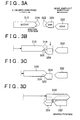
FIGS. 3A to 3D are diagrams showing actions of the synchromesh mechanism shown inFIG. 2 ; -
FIG. 4 is a block diagram showing functions of a control device in accordance with an embodiment of the invention; -
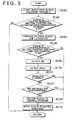
FIG. 5 is a flowchart showing a control process of an ECU in accordance with an embodiment of the invention; -
FIG. 6 is a diagram showing a relationship among a neutral position, a geared position, an actuator drive preparation position, and a gear jump-out position of a sleeve; and -
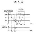
FIGS. 7 and8 are timing charts regarding the amount of movement of the sleeve in accordance with an embodiment of the invention. - Hereinafter, embodiments of the invention will be described with reference to the drawings. In the following description, the component parts are assigned with the same reference characters. Those components are the same in name and function. Therefore, detailed descriptions thereof will not be repeated.
- With reference to
FIG 1 , a transmission equipped with a control device in accordance with an embodiment of the invention will be described. This transmission includes atransmission case 100, agear shift mechanism 200, asynchromesh mechanism 300, aselect actuator 400, ashift actuator 500, and anECU 600 that is connected to theselect actuator 400 and theshift actuator 500. - The
gear shift mechanism 200 is made up of aninput shaft 202, a counter shaft (not shown), anoutput shaft 204, and gear trains that are connected to these shafts and held in a constantly meshed state. The gears of the train on theoutput shaft 204 are individually connected thereto so that they can be idled relative to theoutput shaft 204. - The
synchromesh mechanism 300 sets thegear shift mechanism 200 at a predetermined transmission gear ratio by switching the state of a predetermined gear of the gear trains of thegear shift mechanism 200 so as to cause the gear to rotate synchronously with theoutput shaft 204. Incidentally, thesynchromesh mechanism 300 will be described in detail below. - The
select actuator 400 selects, from the gears of thesynchromesh mechanism 300, a gear that corresponds to a transmission gear ratio to be set, through a shift-operation of a select shaft. Theselect actuator 400 becomes unnecessary if ashift actuator 500 is provided for each shift fork. Hereinafter, a case where theshift actuator 500 provided for each of the shift forks is controlled will be described. - The
shift actuator 500 moves asleeve 310 of the synchromesh mechanism 300 (described below) in an axis direction X by the line oil pressure. The shift actuators 500 are not limited to a hydraulic type. Alternatively, electrically-operated motor may also be employed. - A
stroke sensor 602, ashift position sensor 606 of ashift lever 604, an input shaftrotation speed sensor 608, and an output shaftrotation speed sensor 610 are connected to theECU 600 via harnesses or the like. - The
stroke sensor 602 detects the amount of movement of thesleeve 310 from a neutral position (the sleeve movement amount) S, and sends a detection signal to theECU 600. - The
shift position sensor 606 detects the position of theshift lever 604, and sends a detection signal to theECU 600. In addition, theshift lever 604 is operated by a driver to a position that corresponds to a gear step the driver desires. - The input shaft
rotation speed sensor 608 detects the rotation speed (input shaft rotation speed) NIN of theinput shaft 202 of thegear shift mechanism 200, and sends a detection signal to theECU 600. - The output shaft
rotation speed sensor 610 detects the rotation speed (output shaft rotation speed) NOUT of theoutput shaft 204 of thegear shift mechanism 200, and sends a detection signal to theECU 600. - The
ECU 600 controls theselect actuator 400 and theshift actuator 500 so that thegear shift mechanism 200 assumes a desired state, based on the detection signals sent from thestroke sensor 602, theshift position sensor 606, the input shaftrotation speed sensor 608, the output shaftrotation speed sensor 610, etc., as well as map and programs stored in a ROM (Read Only Memory). - With reference to
FIG. 2 , thesynchromesh mechanism 300 will be described. Thesynchromesh mechanism 300 includes thesleeve 310 engaged with the shift forks (not shown), asynchronizer ring 320, and a shiftingkey 316. - The
sleeve 310 is fitted to outer peripheral splines of a clutch hub (not shown) connected to theoutput shaft 204, via innerperipheral splines 312 of thesleeve 310. Thesleeve 310 is moved in the axis direction X by theshift actuator 500. - The
synchronizer ring 320 is formed in a cone shape. As thesynchronizer ring 320 is pressurized by thesleeve 310 in the axis direction X, acone surface 326 of thesynchronizer ring 320 contacts acone surface 336 of agear 330 that is idling on theoutput shaft 204 at a rotation speed synchronous with that of theinput shaft 202. Outerperipheral teeth 324 are formed on the outer periphery of thesynchronizer ring 320 so as to mesh with the innerperipheral splines 312 of thesleeve 310. - The shifting
key 316 is fitted to an inner peripheral surface of thesleeve 310 in centrifugal directions, and pressurizes an end surface of thesynchronizer ring 320 in the axis direction X during an early period of the movement in the axis direction X (in a shift-in region described below). - With reference to
FIG. 3 , actions of thesynchromesh mechanism 300 will be described. During a neutral state of thegear shift mechanism 200, thesleeve 310 is held at a neutral position as shown inFIG 3A . - When the
sleeve 310 starts to move in the axis direction X (hereinafter, this period will be also termed "shift-in region"), the shifting key 316 also moves in the axis direction X and pressurizes the end surface of thesynchronizer ring 320 in the same axis direction. - The shifting
key 316 is positioned so as to rotate at a position that is relatively near to one side of the grooves of the outerperipheral teeth 324 of thesynchronizer ring 320. Therefore, as shown inFIG. 3B , the phases ofchamfered surfaces 314 of the innerperipheral splines 312 and chamferedsurfaces 322 of the outerperipheral teeth 324 of thesynchronizer ring 320 are restricted so as to always facing each other in mutually deviated phases. - Therefore, the
sleeve 310 can be further moved in the axis direction X, so that thechamfered surfaces 314 of thesleeve 310 pressurize the chamferedsurfaces 322 of thesynchronizer ring 320 as shown inFIG. 3C . Therefore, large friction force occurs on thecone surface 326 of thesynchronizer ring 320 and thecone surface 336 of thegear 330. Furthermore, when the innerperipheral splines 312 of thesleeve 310 enters the groove spaces between the outerperipheral teeth 324 of the synchronizer ring 320 (hereinafter, this region will also be termed "synchronization region"), thesleeve 310 directly pressurizes thesynchronizer ring 320 in the axis direction X so that the rotation of thegear 330 synchronizes with the rotation of thesynchronizer ring 320. - After the synchronization is completed, the
synchronizer ring 320 assumes an idle state, and thesleeve 310 is moved further in the axis direction X. At the time point at which an end surface of thesleeve 310 contacts astopper 334, the innerperipheral splines 312 enter the groove spaces betweenexternal teeth 332 as shown inFIG 3D (hereinafter, this period will be termed "push-through region"), thus completing the shift (gear engagement). - If a vehicle equipped with a transmission constructed as described above receives a shock due to a sharp acceleration or deceleration, a run on a rough surface road, a run over bumps, etc., the
sleeve 310 may sometimes move from the position where thesleeve 310 is in contact with the stopper 334 (the geared position) to a neutral position side (in a gear jump-out direction) and therefore the gear may jump out. During the gear jumped-out state, the transmission is in a neutral state although the driver does not intend to have such a state. Therefore, the duration of the gear jumped-out state needs to be made short. - If the
sleeve 310 is moved from the gear jumped-out state directly to the geared position, the duration of the gear jumped-out state can be made short. However, abnormal gear noise can occur if theinput shaft 202 and theoutput shaft 204 are not synchronous. - Therefore, in this embodiment, during the gear jumped-out state, it is determined whether the
input shaft 202 and theoutput shaft 204 are synchronous. Based on the result of the determination, it is selected whether to move thesleeve 310 to the geared position after returning thesleeve 310 to the neutral position or move thesleeve 310 directly to the geared position without returning it to the neutral position. - With reference to
FIG. 4 , a functional block diagram of the control device in accordance with this embodiment will be described. As shown inFIG 4 , this control device includes a gearstate determination portion 620, an actuatordrive preparation portion 630, asynchronization determination portion 640, a vehiclestop determination portion 650, and anactuator control portion 660. - The gear
state determination portion 620 determines the state of the gears of the gear shift mechanism 200 (i.e., whether a gear has jumped out) based on the sleeve movement amount S from thestroke sensor 602. - The actuator
drive preparation portion 630 sends to the shift actuator 500 a control signal that heightens the line oil pressure of theshift actuator 500 beforehand so that a delay in the driving of theshift actuator 500 will not occur, based on the result of the determination by the gearstate determination portion 620. - The
synchronization determination portion 640 determines whether theinput shaft 202 and theoutput shaft 204 are synchronous based on the input shaft rotation speed NIN from the input shaftrotation speed sensor 608 and the output shaft rotation speed NOUT from the output shaftrotation speed sensor 610. - The vehicle
stop determination portion 650 determines whether the vehicle is at a stop based on the output shaft rotation speed NOUT from the output shaftrotation speed sensor 610. - The
actuator control portion 660 sends a control signal to theshift actuator 500 so that thesleeve 310 of thegear shift mechanism 200 is moved to control the state of gears based on the results of determination from the gearstate determination portion 620, thesynchronization determination portion 640 and the vehiclestop determination portion 650. - The control device in accordance with the embodiment that has functional blocks as described above may be realized by a hardware device that is constructed mainly of digital circuits and analog circuits. Alternatively, the control device may also be realized by a software device that is made mainly of a CPU (Central Processing Unit) and a memory that are included in the ECU, and programs that are read from the memory and are executed by the CPU. Generally, it is said that the realization of the control device by a hardware device is advantageous in the operation speed, and the realization thereof by a software device is advantageous in the changing of the design. Hereinafter, the realization of the control device as a software construction will be described. Incidentally, a recording medium in which such programs are recorded is also an aspect of the invention.
- With reference to
FIG 5 , a control process of a program that theECU 600 in accordance with the embodiment executes will be described. Incidentally, this program is executed repeatedly at predetermined intervals. - In step (hereinafter, abbreviated as "S") 100, the
ECU 600 starts to monitor the amount S of movement of thesleeve 310 from the neutral position (sleeve movement amount) based on the signal from thestroke sensor 602. - In S102, the
ECU 600 determines whether the position of thesleeve 310 is to the neutral position side of an actuator drive preparation position SA based on the sleeve movement amount S. The actuator drive preparation position SA, as shown inFIG. 6 , is set at a position that is to the neutral position side of the geared position SMAX at which thesleeve 310 contacts thestopper 334, and that is a position of a predetermined value ΔS to the geared position SMAX side of a gear jump-out position SB at which the gear jumped-out state occurs. In addition, the gear jump-out position SB is determined beforehand as a value at which the gear jumped-out state is possible, through experiments or the like, taking into consideration the variation of the mounting accuracy of thesleeve 310, thegear 330 and thestopper 334. Besides, the predetermined value ΔS is determined beforehand through experiments or the like, as a time period which elapses until the position of thesleeve 310 reaches the gear jump-out position SB and during which the line pressure of theshift actuator 500 can be held sufficiently high. If the position of thesleeve 310 is to the neutral position side of the actuator drive preparation position SA (YES in S102), the process proceeds to S104. Otherwise (NO in S102), this process ends. - In S104, the
ECU 600 sends to the shift actuator 500 a control signal for heightening the line oil pressure of theshift actuator 500 beforehand so as to prevent a delay in the driving of theshift actuator 500. - In S106, the
ECU 600 determines whether the position of thesleeve 310 is to the neutral position side of the gear jump-out position SB (seeFIG. 6 ) based on the sleeve movement amount S. If the position of thesleeve 310 is to the neutral position side of the gear jump-out position SB (YES in S106), the process proceeds to S108. Otherwise (NO in S106), the process proceeds to S118. - In S108, the
ECU 600 detects the input shaft rotation speed NIN based on the signal from the input shaftrotation speed sensor 608. - In S110, the
ECU 600 detects the output shaft rotation speed NOUT based on the signal from the output shaftrotation speed sensor 610. - In S112, the
ECU 600 determines whether the vehicle is at a stop based on the output shaft rotation speed NOUT. If the vehicle is at a stop (YES in S112), the process proceeds to S118. Otherwise (NO in S112), the process proceeds to S 114. - In S114, the
ECU 600 determines whether the input shaft rotation speed NIN and the output shaft rotation speed NOUT are synchronous. TheECU 600 determines that the input shaft rotation speed NIN and the output shaft rotation speed NOUT are synchronous, for example, in the case where the input shaft rotation speed NIN is within a range that is determined beforehand from the product of the output shaft rotation speed NOUT and the transmission gear ratio. If the input shaft rotation speed NIN and the output shaft rotation speed NOUT are synchronous (YES in S114), the process proceeds to S118. Otherwise (NO in S114), the process proceeds to S116. - In S116, the
ECU 600 sends to theshift actuator 500 such a control signal as to return thesleeve 310 to the neutral position. - In S118, the
ECU 600 sends to theshift actuator 500 such a control signal as to move thesleeve 310 to the geared position SMAX. - Actions of the vehicle controlled by the
ECU 600 in accordance with the embodiment based on the foregoing flowchart will be described. - Firstly, let it assumed that, as shown in
FIG. 7 , thesleeve 310 moves from the geared position SMAX to the neutral position side, and reaches the actuator drive preparation position SA at a time T1 (YES in S102). - In this case, at the time T1, the line oil pressure of the
shift actuator 500 is heightened beforehand (S104). After that, at a time T2, if it is determined that thesleeve 310 has not moved to the gear jump-out position SB (NO in S106), thesleeve 310 is not returned to the neutral position, but is returned directly to the geared position SMAX (S118). Thus, thesleeve 310 is moved to the geared position SMAX before the gear jumped-out state occurs. Hence, occurrence of the gear jumped-out state can be prevented. - Furthermore, since the line oil pressure of the
shift actuator 500 is heightened in advance at the time T1, the time of completion of the gear engagement can be advanced from a time T4 to a time T3, in comparison with the case where the line oil pressure of theshift actuator 500 is heightened at the time T2 (a dashed-dotted line inFIG. 7 ). Therefore, the gear re-arrangement time can be shortened. - Next, let it assumed that, as shown in
FIG. 8 , thesleeve 310 moves from the geared position SMAX to the neutral position side and the position of thesleeve 310 reaches the gear jump-out position SB at a time T6. - At the time T6, in the case where the vehicle is at a stop (YES in S112), or in the case where the input shaft rotation speed NIN and the output shaft rotation speed NOUT are synchronous (YES in S114), returning the
sleeve 310 directly to the geared position SMAX without returning it to the neutral position does not cause occurrence of the abnormal gear noise or the like. - Therefore, the
sleeve 310 is returned directly to the geared position SMAX without returning it to the neutral position (S118). Therefore, the time of completion of the gear engagement can be advanced from a time T8 to a time T7, in comparison with the case where thesleeve 310 is returned to the geared position SMAX after being returned to the neutral position (a dashed-dotted line inFIG. 8 ). Therefore, unnecessary prolongation of the gear re-arrangement time is restrained, and therefore the gear re-arrangement time can be shortened. - Furthermore, at a time T5 when the
sleeve 310 reaches the actuator drive preparation position SA, the line oil pressure of theshift actuator 500 is heightened in advance (S104). Therefore, the time of completion of the gear engagement can be advanced from a time T9 to a time T7, in comparison with the case where the line oil pressure of theshift actuator 500 is heightened at the time T6 following the time T5 (a dashed-two dotted line inFIG. 8 ). Therefore, the delay of the time at which thesleeve 310 starts to move after theactuator 500 receives a movement command regarding thesleeve 310 can be restrained, and prolongation of the gear re-arrangement time can be restrained. - Thus, according to the control device in accordance with the embodiment, in the case where a gear jump-out occurs in a transmission that automatically performs the gear shifting by using a synchromesh mechanism and an actuator that controls the synchromesh mechanism, the actuator is controlled so as so to return the sleeve directly to the geared position without returning it to the neutral position if the input shaft and the output shaft of the transmission are synchronous or if the vehicle is at a stop. Therefore, the control device can shorten the gear re-arrangement time while restraining the occurrence of the abnormal gear noise at the time of engaging a gear.
- While the invention has been described with reference to example embodiments thereof, it is to be understood that the invention is not limited to the described embodiments or constructions. To the contrary, the invention is intended to cover various modifications and equivalent arrangements. In addition, while the various elements of the example embodiments are shown in various combinations and configurations, other combinations and configurations, including more, less or only a single element, are also within the spirit and scope of the invention.
Claims (18)
- A transmission control device that automatically performs a gear shift by using a synchromesh mechanism (300) and an actuator (500) that controls the synchromesh mechanism (300), the synchromesh mechanism (300) having a sleeve (310) that is connected to one of an input shaft (202) and an output shaft (204) of a transmission (200), the sleeve (310) moving from a neutral position to a geared position (SMAX) and meshing with a gear (330) in synchronization, the gear (330) being rotated in synchronous with the other of the input shaft (202) and the output shaft (204), the transmission control device characterized by comprising:movement amount detection means (602) for detecting a movement amount (S) of the sleeve (310);determination means (620) for determining whether the sleeve (310) is jumped out of the gear (330) based on the movement amount (S) of the sleeve (310); andactuator control means (660) for controlling the actuator (500) based on at least a synchronous state of the input shaft (202) and the output shaft (204) if it is determined that the sleeve (310) is jumped out of the gear (330).
- The transmission control device according to claim 1, wherein the determination means (620) determines that the sleeve (310) is jumped out of the gear (330) if the movement amount (S) of the sleeve (310) reaches a first predetermined value (SB).
- The transmission control device according to claim 1 or 2, wherein if it is determined that the sleeve (310) is jumped out of the gear (330), the actuator control means (660) selects one of a first control mode of the actuator (500) that moves the sleeve (310) to the geared position (SMAX) after once returning the sleeve (310) to the neutral position and a second control mode that moves the sleeve (310) to the geared position (SMAX) without returning the sleeve (310) to the neutral position, and controls the actuator (500) according to the selected control mode.
- The transmission control device according to claim 3, wherein the actuator control means (660) selects the control mode of the actuator (500) based on a rotation speed (NIN) of the input shaft (202) and a rotation speed (NOUT) of the output shaft (204).
- The transmission control device according to claim 3 or 4, wherein the actuator control means (660) selects the second control mode if the rotation speed (NIN) of the input shaft (202) and the rotation speed (NOUT) of the output shaft (204) are synchronous.
- The transmission control device according to claim 3 or 4, wherein the actuator control means (660) selects the first control mode if the rotation speed (NIN) of the input shaft (202) and the rotation speed (NOUT) of the output shaft (204) are not synchronous.
- The transmission control device according to claim 3, wherein the actuator control means (660) selects the second control mode if a vehicle equipped with the transmission (200) is in a stopped state.
- The transmission control device according to any one of claims 2 to 7, further comprising actuator drive preparation means (630) for preparing to move the sleeve (310) to the geared position (SMAX) by using the actuator (500) when the movement amount (S) of the sleeve (310) reaches a second predetermined value (SA) that is between a first predetermined value (SB) and the geared position (SMAX).
- The transmission control device according to claim 8, wherein:the actuator (500) is hydraulically controlled; anda line oil pressure of the actuator (500) is heightened when the movement amount (S) of the sleeve (310) reaches the second predetermined value (SA).
- A transmission control method that automatically performs a gear shift by using a synchromesh mechanism (300) and an actuator (500) that controls the synchromesh mechanism (300), the synchromesh mechanism (300) having a sleeve (310) that is connected to one of an input shaft (202) and an output shaft (204) of a transmission (200), the sleeve (310) moving from a neutral position to a geared position (SMAX) and meshing with a gear (330) in synchronization, the gear (330) being rotated in synchronous with the other of the input shaft (202) and the output shaft (204), the transmission control method characterized by comprising:detecting a movement amount (S) of the sleeve (310);determining whether the sleeve (310) is jumped out of the gear (330) based on the movement amount (S) of the sleeve (310); andcontrolling the actuator (500) based on at least a synchronous state of the input shaft (202) and the output shaft (204) if it is determined that the sleeve (310) is jumped out of the gear (330).
- The transmission control method according to claim 10, wherein it is determined that the sleeve (310) is jumped out of the gear (330) if the movement amount (S) of the sleeve (310) reaches a first predetermined value (SB).
- The transmission control method according to claim 10 or 11, wherein:if it is determined that the sleeve (310) is jumped out of the gear (330), selecting one of a first control mode of the actuator (500) that moves the sleeve (310) to the geared position (SMAX) after once returning the sleeve (310) to the neutral position and a second control mode that moves the sleeve (310) to the geared position (SMAX) without returning the sleeve (310) to the neutral position, andcontrolling the actuator (500) according to the selected control mode.
- The transmission control method according to claim 12, wherein selecting the control mode based on a rotation speed (NIN) of the input shaft (202) and a rotation speed (NOUT) of the output shaft (204).
- The transmission control method according to claim 12 or 13, wherein selecting the second control mode if the rotation speed (NIN) of the input shaft (202) and the rotation speed (NOUT) of the output shaft (204) are synchronous.
- The transmission control method according to claim 12 or 13, wherein selecting the first control mode if the rotation speed (NIN) of the input shaft (202) and the rotation speed (NOUT) of the output shaft (204) are not synchronous.
- The transmission control method according to claim 12, wherein selecting the second control mode if a vehicle equipped with the transmission (200) is in a stopped state.
- The transmission control method according to any one of claims 11 to 16, further comprising preparing to move the sleeve (310) to the geared position (SMAX) by using the actuator (500) when the movement amount (S) of the sleeve (310) reaches a second predetermined value (SA) that is between a first predetermined value (SB) and the geared position (SMAX).
- The transmission control method according to claim 17, further comprising heightening a line oil pressure of the actuator (500) that is hydraulically controlled when the movement amount (S) of the sleeve (310) reaches the second predetermined value (SA).
Applications Claiming Priority (1)
| Application Number | Priority Date | Filing Date | Title |
|---|---|---|---|
| JP2007039381A JP4412334B2 (en) | 2007-02-20 | 2007-02-20 | Transmission control device, control method, program for realizing the method, and recording medium recording the program |
Publications (3)
| Publication Number | Publication Date |
|---|---|
| EP1961999A2 true EP1961999A2 (en) | 2008-08-27 |
| EP1961999A3 EP1961999A3 (en) | 2010-12-08 |
| EP1961999B1 EP1961999B1 (en) | 2011-11-30 |
Family
ID=39494582
Family Applications (1)
| Application Number | Title | Priority Date | Filing Date |
|---|---|---|---|
| EP20080250567 Not-in-force EP1961999B1 (en) | 2007-02-20 | 2008-02-19 | Control device and control method of transmission |
Country Status (2)
| Country | Link |
|---|---|
| EP (1) | EP1961999B1 (en) |
| JP (1) | JP4412334B2 (en) |
Cited By (1)
| Publication number | Priority date | Publication date | Assignee | Title |
|---|---|---|---|---|
| US10118619B2 (en) | 2014-08-29 | 2018-11-06 | Toyota Jidosha Kabushiki Kaisha | Vehicle control device and control method |
Families Citing this family (4)
| Publication number | Priority date | Publication date | Assignee | Title |
|---|---|---|---|---|
| US8725371B2 (en) | 2009-03-05 | 2014-05-13 | Toyota Jidosha Kabushiki Kaisha | Speed changing control apparatus for vehicle |
| JP5077269B2 (en) | 2009-03-05 | 2012-11-21 | トヨタ自動車株式会社 | Vehicle shift control device |
| JP5712938B2 (en) * | 2012-01-17 | 2015-05-07 | トヨタ自動車株式会社 | Vehicle transmission control device |
| JP6070380B2 (en) * | 2013-04-16 | 2017-02-01 | アイシン精機株式会社 | Automatic transmission for automatic transmission for vehicle |
Citations (2)
| Publication number | Priority date | Publication date | Assignee | Title |
|---|---|---|---|---|
| JPH0221646Y2 (en) | 1984-07-24 | 1990-06-11 | ||
| JP2000205410A (en) | 1999-01-14 | 2000-07-25 | Aisin Ai Co Ltd | Automatically operated transmission |
Family Cites Families (3)
| Publication number | Priority date | Publication date | Assignee | Title |
|---|---|---|---|---|
| JP2002147590A (en) * | 2000-11-09 | 2002-05-22 | Isuzu Motors Ltd | Transmission control device for transmission |
| US6883394B2 (en) * | 2002-10-15 | 2005-04-26 | Borgwarner, Inc. | Method for controlling the positioning of the synchronizers of a dual clutch transmission |
| US6935204B2 (en) * | 2003-10-31 | 2005-08-30 | Caterpillar Inc | Automated manual transmission and shift method |
-
2007
- 2007-02-20 JP JP2007039381A patent/JP4412334B2/en not_active Expired - Fee Related
-
2008
- 2008-02-19 EP EP20080250567 patent/EP1961999B1/en not_active Not-in-force
Patent Citations (2)
| Publication number | Priority date | Publication date | Assignee | Title |
|---|---|---|---|---|
| JPH0221646Y2 (en) | 1984-07-24 | 1990-06-11 | ||
| JP2000205410A (en) | 1999-01-14 | 2000-07-25 | Aisin Ai Co Ltd | Automatically operated transmission |
Cited By (1)
| Publication number | Priority date | Publication date | Assignee | Title |
|---|---|---|---|---|
| US10118619B2 (en) | 2014-08-29 | 2018-11-06 | Toyota Jidosha Kabushiki Kaisha | Vehicle control device and control method |
Also Published As
| Publication number | Publication date |
|---|---|
| JP4412334B2 (en) | 2010-02-10 |
| JP2008202684A (en) | 2008-09-04 |
| EP1961999B1 (en) | 2011-11-30 |
| EP1961999A3 (en) | 2010-12-08 |
Similar Documents
| Publication | Publication Date | Title |
|---|---|---|
| JP4341687B2 (en) | Control device and control method for automatic transmission | |
| JP4163479B2 (en) | Multi-clutch transmission output shaft locking device | |
| EP1837560B1 (en) | Automated manual transmission and method for controlling the same | |
| EP2042400B1 (en) | Control apparatus of vehicle | |
| JP2010506103A (en) | Method for eliminating tooth-to-tooth collision during gear insertion in a transmission | |
| EP1961999B1 (en) | Control device and control method of transmission | |
| JP2015127508A (en) | Shift control device | |
| JP4313452B2 (en) | Automatic operation transmission | |
| JP4616625B2 (en) | Automatic transmission control device | |
| US10093319B2 (en) | Variable speed control system | |
| JP2012228923A (en) | Motor assist control device and method | |
| EP1767821B1 (en) | Gear shifting completion determining device and gear shifting completion determining method | |
| JP2006070911A (en) | Transmission system | |
| JP6565008B2 (en) | Automatic transmission | |
| JP2009191868A (en) | Vehicle control apparatus and control method | |
| JP4966839B2 (en) | Control method of gear transmission | |
| JP4172188B2 (en) | Shift control device for mechanical automatic transmission | |
| JPH01312254A (en) | Automatic transmission | |
| EP1584848B1 (en) | Automatic shift operation controlling apparatus for a vehicle and method of detecting a balk point in the same | |
| JP2004076841A (en) | Automatic transmission control device for vehicles | |
| JP6224482B2 (en) | Shifting device for automatic transmission | |
| JP2005282741A (en) | Control device for hybrid vehicle | |
| US20010027691A1 (en) | Automatic trasmission | |
| JP2002188714A (en) | Pre-boke controlling method for automatic transmission | |
| JP2014173672A (en) | Gear change control device of vehicle |
Legal Events
| Date | Code | Title | Description |
|---|---|---|---|
| PUAI | Public reference made under article 153(3) epc to a published international application that has entered the european phase |
Free format text: ORIGINAL CODE: 0009012 |
|
| 17P | Request for examination filed |
Effective date: 20080317 |
|
| AK | Designated contracting states |
Kind code of ref document: A2 Designated state(s): AT BE BG CH CY CZ DE DK EE ES FI FR GB GR HR HU IE IS IT LI LT LU LV MC MT NL NO PL PT RO SE SI SK TR |
|
| AX | Request for extension of the european patent |
Extension state: AL BA MK RS |
|
| PUAL | Search report despatched |
Free format text: ORIGINAL CODE: 0009013 |
|
| AK | Designated contracting states |
Kind code of ref document: A3 Designated state(s): AT BE BG CH CY CZ DE DK EE ES FI FR GB GR HR HU IE IS IT LI LT LU LV MC MT NL NO PL PT RO SE SI SK TR |
|
| AX | Request for extension of the european patent |
Extension state: AL BA MK RS |
|
| GRAP | Despatch of communication of intention to grant a patent |
Free format text: ORIGINAL CODE: EPIDOSNIGR1 |
|
| RIC1 | Information provided on ipc code assigned before grant |
Ipc: F16H 61/04 20060101AFI20110505BHEP |
|
| RIN1 | Information on inventor provided before grant (corrected) |
Inventor name: SHIMIZU, MASATOC/O TOYOTA JIDOSHA K.K. |
|
| AKX | Designation fees paid |
Designated state(s): DE FR GB IT |
|
| GRAS | Grant fee paid |
Free format text: ORIGINAL CODE: EPIDOSNIGR3 |
|
| GRAA | (expected) grant |
Free format text: ORIGINAL CODE: 0009210 |
|
| AK | Designated contracting states |
Kind code of ref document: B1 Designated state(s): DE FR GB IT |
|
| REG | Reference to a national code |
Ref country code: GB Ref legal event code: FG4D |
|
| REG | Reference to a national code |
Ref country code: DE Ref legal event code: R096 Ref document number: 602008011679 Country of ref document: DE Effective date: 20120216 |
|
| PG25 | Lapsed in a contracting state [announced via postgrant information from national office to epo] |
Ref country code: IT Free format text: LAPSE BECAUSE OF FAILURE TO SUBMIT A TRANSLATION OF THE DESCRIPTION OR TO PAY THE FEE WITHIN THE PRESCRIBED TIME-LIMIT Effective date: 20111130 |
|
| PLBE | No opposition filed within time limit |
Free format text: ORIGINAL CODE: 0009261 |
|
| STAA | Information on the status of an ep patent application or granted ep patent |
Free format text: STATUS: NO OPPOSITION FILED WITHIN TIME LIMIT |
|
| GBPC | Gb: european patent ceased through non-payment of renewal fee |
Effective date: 20120229 |
|
| 26N | No opposition filed |
Effective date: 20120831 |
|
| REG | Reference to a national code |
Ref country code: FR Ref legal event code: ST Effective date: 20121031 |
|
| REG | Reference to a national code |
Ref country code: DE Ref legal event code: R097 Ref document number: 602008011679 Country of ref document: DE Effective date: 20120831 |
|
| REG | Reference to a national code |
Ref country code: DE Ref legal event code: R084 Ref document number: 602008011679 Country of ref document: DE Effective date: 20121115 |
|
| PG25 | Lapsed in a contracting state [announced via postgrant information from national office to epo] |
Ref country code: FR Free format text: LAPSE BECAUSE OF NON-PAYMENT OF DUE FEES Effective date: 20120229 Ref country code: GB Free format text: LAPSE BECAUSE OF NON-PAYMENT OF DUE FEES Effective date: 20120229 |
|
| PGFP | Annual fee paid to national office [announced via postgrant information from national office to epo] |
Ref country code: DE Payment date: 20170214 Year of fee payment: 10 |
|
| REG | Reference to a national code |
Ref country code: DE Ref legal event code: R119 Ref document number: 602008011679 Country of ref document: DE |
|
| PG25 | Lapsed in a contracting state [announced via postgrant information from national office to epo] |
Ref country code: DE Free format text: LAPSE BECAUSE OF NON-PAYMENT OF DUE FEES Effective date: 20180901 |