EP1961938A2 - Control system for general-purpose engine - Google Patents
Control system for general-purpose engine Download PDFInfo
- Publication number
- EP1961938A2 EP1961938A2 EP08250607A EP08250607A EP1961938A2 EP 1961938 A2 EP1961938 A2 EP 1961938A2 EP 08250607 A EP08250607 A EP 08250607A EP 08250607 A EP08250607 A EP 08250607A EP 1961938 A2 EP1961938 A2 EP 1961938A2
- Authority
- EP
- European Patent Office
- Prior art keywords
- cylinders
- throttle
- engine
- driver
- fuel
- Prior art date
- Legal status (The legal status is an assumption and is not a legal conclusion. Google has not performed a legal analysis and makes no representation as to the accuracy of the status listed.)
- Granted
Links
- 238000001816 cooling Methods 0.000 claims abstract description 40
- 239000000446 fuel Substances 0.000 claims abstract description 40
- 238000002485 combustion reaction Methods 0.000 claims abstract description 18
- 238000000034 method Methods 0.000 claims description 11
- 238000011144 upstream manufacturing Methods 0.000 claims description 5
- 230000000694 effects Effects 0.000 abstract description 9
- 238000002347 injection Methods 0.000 description 7
- 239000007924 injection Substances 0.000 description 7
- 230000001105 regulatory effect Effects 0.000 description 6
- 230000001276 controlling effect Effects 0.000 description 5
- 239000003990 capacitor Substances 0.000 description 3
- 238000007664 blowing Methods 0.000 description 2
- 238000001514 detection method Methods 0.000 description 2
- 238000010586 diagram Methods 0.000 description 2
- 239000003502 gasoline Substances 0.000 description 2
- 239000000203 mixture Substances 0.000 description 2
- 238000006073 displacement reaction Methods 0.000 description 1
- 239000002360 explosive Substances 0.000 description 1
- 239000002828 fuel tank Substances 0.000 description 1
- 238000005192 partition Methods 0.000 description 1
- 238000005086 pumping Methods 0.000 description 1
Images



Classifications
-
- F—MECHANICAL ENGINEERING; LIGHTING; HEATING; WEAPONS; BLASTING
- F02—COMBUSTION ENGINES; HOT-GAS OR COMBUSTION-PRODUCT ENGINE PLANTS
- F02D—CONTROLLING COMBUSTION ENGINES
- F02D41/00—Electrical control of supply of combustible mixture or its constituents
- F02D41/0002—Controlling intake air
-
- F—MECHANICAL ENGINEERING; LIGHTING; HEATING; WEAPONS; BLASTING
- F01—MACHINES OR ENGINES IN GENERAL; ENGINE PLANTS IN GENERAL; STEAM ENGINES
- F01P—COOLING OF MACHINES OR ENGINES IN GENERAL; COOLING OF INTERNAL-COMBUSTION ENGINES
- F01P1/00—Air cooling
-
- F—MECHANICAL ENGINEERING; LIGHTING; HEATING; WEAPONS; BLASTING
- F02—COMBUSTION ENGINES; HOT-GAS OR COMBUSTION-PRODUCT ENGINE PLANTS
- F02B—INTERNAL-COMBUSTION PISTON ENGINES; COMBUSTION ENGINES IN GENERAL
- F02B75/00—Other engines
- F02B75/16—Engines characterised by number of cylinders, e.g. single-cylinder engines
- F02B75/18—Multi-cylinder engines
- F02B75/22—Multi-cylinder engines with cylinders in V, fan, or star arrangement
-
- F—MECHANICAL ENGINEERING; LIGHTING; HEATING; WEAPONS; BLASTING
- F02—COMBUSTION ENGINES; HOT-GAS OR COMBUSTION-PRODUCT ENGINE PLANTS
- F02D—CONTROLLING COMBUSTION ENGINES
- F02D17/00—Controlling engines by cutting out individual cylinders; Rendering engines inoperative or idling
-
- F—MECHANICAL ENGINEERING; LIGHTING; HEATING; WEAPONS; BLASTING
- F02—COMBUSTION ENGINES; HOT-GAS OR COMBUSTION-PRODUCT ENGINE PLANTS
- F02D—CONTROLLING COMBUSTION ENGINES
- F02D41/00—Electrical control of supply of combustible mixture or its constituents
- F02D41/008—Controlling each cylinder individually
- F02D41/0085—Balancing of cylinder outputs, e.g. speed, torque or air-fuel ratio
-
- F—MECHANICAL ENGINEERING; LIGHTING; HEATING; WEAPONS; BLASTING
- F02—COMBUSTION ENGINES; HOT-GAS OR COMBUSTION-PRODUCT ENGINE PLANTS
- F02D—CONTROLLING COMBUSTION ENGINES
- F02D9/00—Controlling engines by throttling air or fuel-and-air induction conduits or exhaust conduits
- F02D9/02—Controlling engines by throttling air or fuel-and-air induction conduits or exhaust conduits concerning induction conduits
- F02D2009/0201—Arrangements; Control features; Details thereof
- F02D2009/0244—Choking air flow at low speed and load
-
- F—MECHANICAL ENGINEERING; LIGHTING; HEATING; WEAPONS; BLASTING
- F02—COMBUSTION ENGINES; HOT-GAS OR COMBUSTION-PRODUCT ENGINE PLANTS
- F02D—CONTROLLING COMBUSTION ENGINES
- F02D9/00—Controlling engines by throttling air or fuel-and-air induction conduits or exhaust conduits
- F02D9/02—Controlling engines by throttling air or fuel-and-air induction conduits or exhaust conduits concerning induction conduits
- F02D2009/0201—Arrangements; Control features; Details thereof
- F02D2009/0296—Throttle control device with stops for limiting throttle opening or closing beyond a certain position during certain periods of operation
-
- F—MECHANICAL ENGINEERING; LIGHTING; HEATING; WEAPONS; BLASTING
- F02—COMBUSTION ENGINES; HOT-GAS OR COMBUSTION-PRODUCT ENGINE PLANTS
- F02D—CONTROLLING COMBUSTION ENGINES
- F02D11/00—Arrangements for, or adaptations to, non-automatic engine control initiation means, e.g. operator initiated
- F02D11/06—Arrangements for, or adaptations to, non-automatic engine control initiation means, e.g. operator initiated characterised by non-mechanical control linkages, e.g. fluid control linkages or by control linkages with power drive or assistance
- F02D11/10—Arrangements for, or adaptations to, non-automatic engine control initiation means, e.g. operator initiated characterised by non-mechanical control linkages, e.g. fluid control linkages or by control linkages with power drive or assistance of the electric type
- F02D2011/101—Arrangements for, or adaptations to, non-automatic engine control initiation means, e.g. operator initiated characterised by non-mechanical control linkages, e.g. fluid control linkages or by control linkages with power drive or assistance of the electric type characterised by the means for actuating the throttles
- F02D2011/102—Arrangements for, or adaptations to, non-automatic engine control initiation means, e.g. operator initiated characterised by non-mechanical control linkages, e.g. fluid control linkages or by control linkages with power drive or assistance of the electric type characterised by the means for actuating the throttles at least one throttle being moved only by an electric actuator
-
- F—MECHANICAL ENGINEERING; LIGHTING; HEATING; WEAPONS; BLASTING
- F02—COMBUSTION ENGINES; HOT-GAS OR COMBUSTION-PRODUCT ENGINE PLANTS
- F02D—CONTROLLING COMBUSTION ENGINES
- F02D37/00—Non-electrical conjoint control of two or more functions of engines, not otherwise provided for
- F02D37/02—Non-electrical conjoint control of two or more functions of engines, not otherwise provided for one of the functions being ignition
-
- F—MECHANICAL ENGINEERING; LIGHTING; HEATING; WEAPONS; BLASTING
- F02—COMBUSTION ENGINES; HOT-GAS OR COMBUSTION-PRODUCT ENGINE PLANTS
- F02D—CONTROLLING COMBUSTION ENGINES
- F02D41/00—Electrical control of supply of combustible mixture or its constituents
- F02D41/30—Controlling fuel injection
- F02D41/3005—Details not otherwise provided for
-
- Y—GENERAL TAGGING OF NEW TECHNOLOGICAL DEVELOPMENTS; GENERAL TAGGING OF CROSS-SECTIONAL TECHNOLOGIES SPANNING OVER SEVERAL SECTIONS OF THE IPC; TECHNICAL SUBJECTS COVERED BY FORMER USPC CROSS-REFERENCE ART COLLECTIONS [XRACs] AND DIGESTS
- Y02—TECHNOLOGIES OR APPLICATIONS FOR MITIGATION OR ADAPTATION AGAINST CLIMATE CHANGE
- Y02T—CLIMATE CHANGE MITIGATION TECHNOLOGIES RELATED TO TRANSPORTATION
- Y02T10/00—Road transport of goods or passengers
- Y02T10/10—Internal combustion engine [ICE] based vehicles
- Y02T10/40—Engine management systems
Definitions
- This invention relates to a system for controlling a general-purpose internal combustion engine, particularly to a control system for a general-purpose internal combustion engine of forced-air-cooled type that sucks in air through a cooling fan and blows for cooling.
- General-purpose engines including the engine disclosed in the prior art mentioned above, are generally air-cooled type.
- engines which produce a large amount of output are often configured to forcibly air-cool by blowing or emitting air sucked in through a fan for cooling. Since the structure of these types of engines results in differences of cooling effect among the cylinders, they are disadvantageously difficult to perform desired output characteristics.
- An object of at least the preferred embodiments of this invention is therefore to overcome the foregoing problems by providing a system for controlling a general-purpose internal combustion engine configured to forcibly air-cool by blowing or emitting air sucked in through a fan for cooling, that can perform desired output characteristics.
- this invention provides a system and method for controlling a general-purpose internal combustion engine having a plurality of cylinders each equipped with a throttle valve that opens/closes an air intake path and a fuel injector that injects fuel into a combustion chamber, and a cooling fan that sucks in and blows air onto the cylinders as cooling air, comprising: a throttle driver that drives an actuator of the throttle valve of each of the cylinders to open/close; an injector driver that drives the fuel injector of each of the cylinders to open; and a controller that controls operation of the throttle driver and injector driver in such a way that the throttle opening and an amount of fuel to be injected are different for each of the cylinders, such that an engine speed becomes constant.
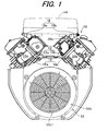
- FIG. 1 is a front view of a general-purpose engine to which a general-purpose engine control system according to an embodiment of this invention is applied
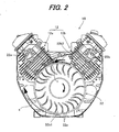
- FIG. 2 is a view, similar to FIG. 1 , but a cooling fan is removed
- FIG. 3 is a top view of the engine shown in FIG. 2 .
- reference numeral 10 designates a general-purpose internal combustion engine.
- the engine 10 is an air-cooled, four-cycle, V2, spark-ignition, gasoline engine equipped with a plurality of (two in this embodiment) cylinders 12 comprising a first cylinder 12a and second cylinder 12b arranged in a V-shape with respect to a crankshaft (not shown).
- the engine 10 has a displacement of, for example, 640 cc and can be used as a prime mover in electric generators, agricultural machinery and various other applications.
- each of the first cylinder 12a and the second cylinder 12b of the engine 10 air sucked in through an air cleaner 14 (only shown in FIG. 1 ) flows through an air intake pipe (air intake path; not shown). Having regulated its flow rate at a first throttle valve or a second throttle valve (neither shown) housed in a first throttle body 16a or a second throttle body 16b, the air is injected with pressurized gasoline fuel (supplied from a fuel tank) by a first fuel injector 18a or a second fuel injector 18b, when the injectors 18a, 18b are driven to open.
- the air-fuel mixture thus produced flows through a first intake manifold 22a or a second intake manifold 22b into a combustion chamber.
- the first and second throttle valves are connected to associated electric motors (neither shown) and driven thereby to be opened and closed.
- a motor drive circuit of the first throttle body 16a is not shown, but that of the second throttle body 16b is designated by reference numeral 20b.
- elements constituting or belonging to the first cylinder 12a are added with a term "first" and suffixed by "a”, and those constituting or belonging to the second cylinder 12b with a term "second" and by "b.”
- the air-fuel mixture produced in the combustion chamber is ignited by a first spark plug 24a or a second spark plug 24b.
- the resulting explosive combustion drives each piston (neither shown) to rotate a crankshaft (not shown) connected thereto, thereby rotating an output shaft 26 connected to the crankshaft.
- the exhaust gas produced by the combustion passes through a first exhaust port 30a or a second exhaust 30b, joins together and passes through an exhaust pipe (not shown) to be discharged to the exterior.
- the output shaft 26 is connected to a load such as an electric generator, agricultural machine or the like.
- the other end of the crankshaft (opposite from the one end where the output shaft 26 is connected) is coupled with a cooling fan 32.
- the cooling fan 32 comprises a plurality of projecting blades 32a. When rotated by the crankshaft, the cooling fan 32 sucks in and blows air onto the first and second cylinders 12a, 12b for cooling.
- the cooling fan 32 is covered by a fan cover 32b.
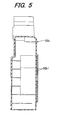
- FIG. 4 is a front view of the fan cover 32b and FIG. 5 is a cross-sectional view taken along line V-V thereof.
- Most part of the fan cover 32b forms multiple air inlets 32b1 by dividing a circular shape as shown in FIG. 4 (and FIG. 1 ) and as shown in FIG. 2 , a scroll or partition 32b2 is formed at the upper portion of the inner side of the air inlets 32b1.
- the scroll 32b2 constitutes a path for guiding cooling air to the second cylinder 12b.
- a part of the cooling air indicated by the arrow a flows to the second cylinder 12b along the scroll 32b2 as indicated by an arrow c in FIG. 2 , flows to cool the second cylinder 12b as indicated by an arrow d in FIG. 3 , and then is discharged to the exterior of the engine 10 through the gaps between the air cleaner 14 and engine body.
- cooling effect at the second cylinder 12b is inferior to the first cylinder 12a.
- the crankshaft is attached with a flywheel (not shown) at the back of the cooling fan 32. Inside of the flywheel is disposed with a power coil (generator coil; not shown) and outside of the flywheel is disposed with a pulsar coil (not shown).
- the power coil and pulsar coil produce outputs (alternating current) synchronously with rotation of the crankshaft.
- An engine speed regulating lever (not shown) is equipped on the engine 10 at a location for the operator to freely manipulate.
- the lever produces an output or signal indicative of an engine speed desired by the operator.
- the outputs of the power coil, pulsar coil and engine speed regulating lever are sent to an Electronic Control Unit (ECU) comprising a microcomputer.
- ECU Electronic Control Unit
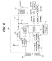
- FIG. 6 is a block diagram functionally showing the structure of the control system of the engine 10 including the ECU and a control circuit.
- the ECU (now assigned with 40) is equipped with a rectifier circuit 42, engine speed (NE) detection circuit 44 and control circuit (controller) 46.
- the output of the power coil (now assigned with 50) is sent to the rectifier circuit 42 to be converted into direct current of 12V through full-wave rectification or the like.
- the direct current is supplied as operating current to components including the ECU 40 of the engine 10 via circuits (not shown).
- the output of the power coil 50 is also sent to the engine speed detection circuit 44 to be converted into a pulse signal through half-wave rectification.
- the produced pulse signal is inputted to the control circuit 46. Since frequency of the alternating current generated by the power coil 50 is proportional to rotation speed of the crankshaft, the control circuit 46 detects the engine speed NE based on the pulse signal generated from the output of the power coil 50.
- the ECU 40 is further equipped with a signal generating circuit 52 and ignition circuit 54.
- the output of the pulsar coil (now assigned with 56) is sent to the signal generating circuit 52 which generates an ignition signal in synchronism with rotation of the crankshaft.
- the ignition signal generated in the signal generating circuit 52 is sent to the ignition circuit 54 and control circuit 46.
- the operating current is boosted at a DC/DC converter 60 and charges a capacitor 62.
- the capacitor 62 is connected to a primary coil of the ignition coil 64 and a secondary coil thereof is connected to the first and second ignition plugs 24a, 24b of the first and second cylinders 12a, 12b.
- the control circuit 46 is supplied with operating current via a circuit (not shown).
- the ignition circuit 54 energizes the gate of a thyristor 66 in response to the ignition signal inputted from the signal generating circuit 52 or control circuit 46.
- the capacitor 62 discharges and current flows through the primary coil of the ignition coil 64 and high voltage is generated at the secondary coil, and accordingly the ignition plugs 24a, 24b produce sparks.
- the control circuit 46 is connected to the engine speed regulating lever (now assigned with 70). Based on the output of the engine speed regulating lever 70 etc., the control circuit 46 determines desired openings of the first and second throttle valves (assigned with 72a, 72b in FIG. 6 ), outputs control signals corresponding to the determined throttle openings to the first and second (throttle) drivers 74a, 74b (same as the driver 20b in FIG. 1 ) to operate the first and second electric throttle motors (assigned with 76a, 76b in FIG. 6 ), thereby separately opening and closing the first and second throttle valves 72a, 72b to regulate the engine speed NE.
- the control circuit 46 also calculates a fuel injection amount to be supplied to each of the first and second cylinders 12a, 12b based on the determined throttle openings and drives the first and second injectors 18a, 18b separately through first and second (injector) drivers 80a, 80b.
- the fuel injection amount to be supplied to the cylinder 12 is determined in terms of opening period of the injector 18, and the control circuit 46 controls the fuel injection amount by regulating the injector opening period through the driver 80.
- the control circuit 46 of the ECU 40 corresponds to the control system of the engine 10.
- FIG. 7 is an explanatory view showing characteristics of throttle opening control performed by the control circuit 46.
- control circuit 46 controls the throttle openings in response to engine load factor, i.e., a rate of load of the engine 10 imparted through the output shaft 26 (the load connected to the output shaft 26 of the engine 10), such that the engine speed NE becomes constant (controlled to the desired value), while controlling the throttle openings of the cylinders 12, i.e., the first and second cylinders 12a, 12b to be different from each other.
- engine load factor i.e., a rate of load of the engine 10 imparted through the output shaft 26 (the load connected to the output shaft 26 of the engine 10)
- the control circuit 46 controls the throttle opening of the first cylinder 12a to be 50 percent and that of the second cylinder 12b to be 0 percent, such that the throttle opening of the engine 10, as a whole, is 25 percent.
- the control circuit 46 controls the throttle opening of the first cylinder 12a to be 100 percent and that of the second cylinder 12b to be 0 percent, such that the throttle opening of the engine 10, as a whole, is 50 percent.
- the engine load factor is 75 percent, it controls the throttle opening of the first cylinder 12a to be 100 percent and that of the second cylinder 12b to be 50 percent, such that the throttle opening of the engine 10, as a whole, is 75 percent.
- the control circuit 46 controls the throttle opening of the first cylinder 12a positioned upstream in the flow of the cooling air to be increased greater than that of the second cylinder 12b positioned downstream, in other words, controls the throttle opening of the second cylinder 12b to decrease greater than that of the first cylinder 12a positioned upstream.
- the second cylinder 12b positioned downstream of the first cylinder in the cooling air flow
- this structure causes an output difference between the cylinders 12, it is configured as described in the foregoing to compensate the difference.
- the control circuit 46 controls the throttle openings of the first and second cylinders 12a, 12b to be the same, i.e., 0 percent or 100 percent. In other words, when the load of the engine is other than zero or full, the control circuit 46 controls the throttle openings of the cylinders to be different from each other.
- the throttle opening is 0 percent at the fully-closed position (more precisely almost fully-closed position), 100 percent at the fully-opened position (more precisely position in the vicinity of 90 degrees), and 50 percent at the middle thereof.
- the throttle opening or engine load factor which is not exemplified in FIG. 7 is calculated by interpolating the values shown in the figure.
- control circuit 46 controls the fuel injection amount based on the controlled throttle opening and engine load factor. Specifically, when the engine load factor is 50 percent, the control circuit 46 controls the fuel injection amount of the first cylinder 12a at a value corresponding to the throttle opening of 100 percent and that of the second cylinder 12b at a value corresponding to the throttle opening of 0 percent.
- the embodiment is configured to have a system for or method of controlling a general-purpose internal combustion engine (10) having a plurality of cylinders (12a, 12b) each equipped with a throttle valve (72a, 72b) that opens/closes an air intake path and a fuel injector (18a, 18b) that injects fuel into a combustion chamber, and a cooling fan (32) that sucks in and blows air onto the cylinders as cooling air, characterized by: a throttle driver (74a, 74b) that drives an actuator (electric motor 76a, 76b) of the throttle valve (72) of each of the cylinders (12) to open/close; an injector driver (80a, 80b) that drives the fuel injector (18) of each of the cylinders (12) to open; and a controller (control circuit 46) that controls operation of the throttle driver (74) and injector driver (80) in such a way that the throttle opening and an amount of fuel to be injected (fuel injection amount) are different for each of the cylinders, such
- the cylinders (12) may be positioned at different locations in flow of the cooling air, and the controller (46) may increase the throttle opening and the amount of fuel to be injected of one of the cylinders (12a) positioned upstream relative to those of the other cylinder (12b) positioned downstream such that the throttle opening and the amount of fuel to be injected are different for each of the cylinders (12).
- the cylinder 12a (that is likely to be cooled) will be controlled to a throttle-opened position more often than the cylinder 12b (that is less likely to be cooled), it becomes possible for the engine 10 as a whole to decrease pumping loss and to reduce heat loss as the combustion state becomes stable.
- the cylinder 12a (that is likely to be cooled) will be controlled to a throttle-opened position more often, it becomes possible to improve control response at a time when load is suddenly imparted.
- the controller (46) may control operation of the throttle driver (74) such that the throttle opening of the cylinders (12) are equal to the rate in percent.
- the controller preferably controls operation of the throttle driver and injector driver such that the throttle opening and the amount of fuel to be injected are different for each of the cylinders, when a load of the engine is other than zero or full.
- the engine (10) is preferably an air-cooled general-purpose engine having two cylinders (12a, 12b).
- the engine 10 having two cylinders i.e., the first and second cylinders 12a, 12b
- the first and second cylinders 12a, 12b can be applied to an engine of forced-air-cooled type that is equipped with more than two cylinders which differ in cooling effect from one another.
Landscapes
- Engineering & Computer Science (AREA)
- Chemical & Material Sciences (AREA)
- Combustion & Propulsion (AREA)
- Mechanical Engineering (AREA)
- General Engineering & Computer Science (AREA)
- Electrical Control Of Air Or Fuel Supplied To Internal-Combustion Engine (AREA)
- Combined Controls Of Internal Combustion Engines (AREA)
- Control Of Throttle Valves Provided In The Intake System Or In The Exhaust System (AREA)
- Output Control And Ontrol Of Special Type Engine (AREA)
Abstract
Description
- This invention relates to a system for controlling a general-purpose internal combustion engine, particularly to a control system for a general-purpose internal combustion engine of forced-air-cooled type that sucks in air through a cooling fan and blows for cooling.
- Among general-purpose engines used as prime movers in electric generators, agricultural machines and various other applications, in recent years, there is proposed a general-purpose engine equipped with a plurality of (e.g., two) cylinders each having a throttle valve for opening and closing air intake path and an injector for injecting fuel for the cylinder, as taught, for example, in Japanese Laid-Open Patent Application No.
2002-349384 - General-purpose engines, including the engine disclosed in the prior art mentioned above, are generally air-cooled type. However, engines which produce a large amount of output, are often configured to forcibly air-cool by blowing or emitting air sucked in through a fan for cooling. Since the structure of these types of engines results in differences of cooling effect among the cylinders, they are disadvantageously difficult to perform desired output characteristics.
- An object of at least the preferred embodiments of this invention is therefore to overcome the foregoing problems by providing a system for controlling a general-purpose internal combustion engine configured to forcibly air-cool by blowing or emitting air sucked in through a fan for cooling, that can perform desired output characteristics.
- In order to achieve the object, this invention provides a system and method for controlling a general-purpose internal combustion engine having a plurality of cylinders each equipped with a throttle valve that opens/closes an air intake path and a fuel injector that injects fuel into a combustion chamber, and a cooling fan that sucks in and blows air onto the cylinders as cooling air, comprising: a throttle driver that drives an actuator of the throttle valve of each of the cylinders to open/close; an injector driver that drives the fuel injector of each of the cylinders to open; and a controller that controls operation of the throttle driver and injector driver in such a way that the throttle opening and an amount of fuel to be injected are different for each of the cylinders, such that an engine speed becomes constant.
- Preferred embodiments of the invention will now be described, by way of example only, and with reference to the accompanying drawings in which:
-
FIG. 1 is a front view of a general-purpose engine to which a general-purpose engine control system according to an embodiment of this invention is applied; -
FIG. 2 is a view, similar toFIG. 1 , but a cooling fan is removed; -
FIG. 3 is a top view of the engine shown inFIG. 2 ; -
FIG. 4 is a front view of the fan cover shown inFIG. 1 ; -
FIG. 5 is a cross-sectional view taken along line V-V of the fan cover shown inFIG. 4 ; -
FIG. 6 is a block diagram functionally showing the structure of a control system of the engine including an ECU and a control circuit and shown inFIG. 1 and other figures; and -
FIG. 7 is an explanatory view showing characteristics of throttle control performed by the control circuit shown inFIG. 6 . - A control system for a general-purpose engine according to a preferred embodiment of the present invention will now be explained with reference to the attached drawings.
-
FIG. 1 is a front view of a general-purpose engine to which a general-purpose engine control system according to an embodiment of this invention is applied,FIG. 2 is a view, similar toFIG. 1 , but a cooling fan is removed andFIG. 3 is a top view of the engine shown inFIG. 2 . - In
FIG. 1 and other figures,reference numeral 10 designates a general-purpose internal combustion engine. Theengine 10 is an air-cooled, four-cycle, V2, spark-ignition, gasoline engine equipped with a plurality of (two in this embodiment)cylinders 12 comprising afirst cylinder 12a andsecond cylinder 12b arranged in a V-shape with respect to a crankshaft (not shown). Theengine 10 has a displacement of, for example, 640 cc and can be used as a prime mover in electric generators, agricultural machinery and various other applications. - In each of the
first cylinder 12a and thesecond cylinder 12b of theengine 10, air sucked in through an air cleaner 14 (only shown inFIG. 1 ) flows through an air intake pipe (air intake path; not shown). Having regulated its flow rate at a first throttle valve or a second throttle valve (neither shown) housed in afirst throttle body 16a or asecond throttle body 16b, the air is injected with pressurized gasoline fuel (supplied from a fuel tank) by afirst fuel injector 18a or asecond fuel injector 18b, when theinjectors first intake manifold 22a or asecond intake manifold 22b into a combustion chamber. - The first and second throttle valves are connected to associated electric motors (neither shown) and driven thereby to be opened and closed. In
FIG. 1 , a motor drive circuit of thefirst throttle body 16a is not shown, but that of thesecond throttle body 16b is designated byreference numeral 20b. As described in the foregoing, elements constituting or belonging to thefirst cylinder 12a are added with a term "first" and suffixed by "a", and those constituting or belonging to thesecond cylinder 12b with a term "second" and by "b." - The air-fuel mixture produced in the combustion chamber is ignited by a
first spark plug 24a or asecond spark plug 24b. The resulting explosive combustion drives each piston (neither shown) to rotate a crankshaft (not shown) connected thereto, thereby rotating anoutput shaft 26 connected to the crankshaft. The exhaust gas produced by the combustion passes through afirst exhaust port 30a or asecond exhaust 30b, joins together and passes through an exhaust pipe (not shown) to be discharged to the exterior. Theoutput shaft 26 is connected to a load such as an electric generator, agricultural machine or the like. - The other end of the crankshaft (opposite from the one end where the
output shaft 26 is connected) is coupled with acooling fan 32. As shown inFIG. 2 , thecooling fan 32 comprises a plurality of projectingblades 32a. When rotated by the crankshaft, thecooling fan 32 sucks in and blows air onto the first andsecond cylinders engine 10 is the type of the forced-air-cooling. Thecooling fan 32 is covered by afan cover 32b. -
FIG. 4 is a front view of thefan cover 32b andFIG. 5 is a cross-sectional view taken along line V-V thereof. Most part of thefan cover 32b forms multiple air inlets 32b1 by dividing a circular shape as shown inFIG. 4 (andFIG. 1 ) and as shown inFIG. 2 , a scroll or partition 32b2 is formed at the upper portion of the inner side of the air inlets 32b1. The scroll 32b2 constitutes a path for guiding cooling air to thesecond cylinder 12b. - As shown in
FIG. 2 , when the crankshaft of theengine 10 rotates clockwise, air sucked in through the air inlets 32b1 flows to thefirst cylinder 12a as indicated by an arrow a in the figure, flows to cool thefirst cylinder 12a as indicated by an arrow b (FIG. 3 ), and then is discharged to the exterior of theengine 10 through gaps between theair cleaner 14 and engine body. - On the other hand, a part of the cooling air indicated by the arrow a flows to the
second cylinder 12b along the scroll 32b2 as indicated by an arrow c inFIG. 2 , flows to cool thesecond cylinder 12b as indicated by an arrow d inFIG. 3 , and then is discharged to the exterior of theengine 10 through the gaps between theair cleaner 14 and engine body. In this case, since thesecond cylinder 12b is located downstream in the cooling air flow, cooling effect at thesecond cylinder 12b is inferior to thefirst cylinder 12a. - Next, a control system of the
engine 10 will be explained. - The crankshaft is attached with a flywheel (not shown) at the back of the
cooling fan 32. Inside of the flywheel is disposed with a power coil (generator coil; not shown) and outside of the flywheel is disposed with a pulsar coil (not shown). The power coil and pulsar coil produce outputs (alternating current) synchronously with rotation of the crankshaft. - An engine speed regulating lever (not shown) is equipped on the
engine 10 at a location for the operator to freely manipulate. The lever produces an output or signal indicative of an engine speed desired by the operator. The outputs of the power coil, pulsar coil and engine speed regulating lever are sent to an Electronic Control Unit (ECU) comprising a microcomputer. -
FIG. 6 is a block diagram functionally showing the structure of the control system of theengine 10 including the ECU and a control circuit. - As illustrated, the ECU (now assigned with 40) is equipped with a
rectifier circuit 42, engine speed (NE)detection circuit 44 and control circuit (controller) 46. The output of the power coil (now assigned with 50) is sent to therectifier circuit 42 to be converted into direct current of 12V through full-wave rectification or the like. The direct current is supplied as operating current to components including theECU 40 of theengine 10 via circuits (not shown). - The output of the
power coil 50 is also sent to the enginespeed detection circuit 44 to be converted into a pulse signal through half-wave rectification. The produced pulse signal is inputted to thecontrol circuit 46. Since frequency of the alternating current generated by thepower coil 50 is proportional to rotation speed of the crankshaft, thecontrol circuit 46 detects the engine speed NE based on the pulse signal generated from the output of thepower coil 50. - The ECU 40 is further equipped with a
signal generating circuit 52 andignition circuit 54. The output of the pulsar coil (now assigned with 56) is sent to thesignal generating circuit 52 which generates an ignition signal in synchronism with rotation of the crankshaft. The ignition signal generated in thesignal generating circuit 52 is sent to theignition circuit 54 andcontrol circuit 46. - The operating current is boosted at a DC/
DC converter 60 and charges acapacitor 62. Thecapacitor 62 is connected to a primary coil of theignition coil 64 and a secondary coil thereof is connected to the first andsecond ignition plugs second cylinders control circuit 46 is supplied with operating current via a circuit (not shown). - The
ignition circuit 54 energizes the gate of athyristor 66 in response to the ignition signal inputted from thesignal generating circuit 52 orcontrol circuit 46. As a result, thecapacitor 62 discharges and current flows through the primary coil of theignition coil 64 and high voltage is generated at the secondary coil, and accordingly theignition plugs - The
control circuit 46 is connected to the engine speed regulating lever (now assigned with 70). Based on the output of the enginespeed regulating lever 70 etc., thecontrol circuit 46 determines desired openings of the first and second throttle valves (assigned with 72a, 72b inFIG. 6 ), outputs control signals corresponding to the determined throttle openings to the first and second (throttle) drivers 74a, 74b (same as thedriver 20b inFIG. 1 ) to operate the first and second electric throttle motors (assigned with 76a, 76b inFIG. 6 ), thereby separately opening and closing the first andsecond throttle valves - The
control circuit 46 also calculates a fuel injection amount to be supplied to each of the first andsecond cylinders second injectors drivers - Specifically, the fuel injection amount to be supplied to the
cylinder 12 is determined in terms of opening period of theinjector 18, and thecontrol circuit 46 controls the fuel injection amount by regulating the injector opening period through the driver 80. Thecontrol circuit 46 of theECU 40 corresponds to the control system of theengine 10. -
FIG. 7 is an explanatory view showing characteristics of throttle opening control performed by thecontrol circuit 46. - As illustrated, the
control circuit 46 controls the throttle openings in response to engine load factor, i.e., a rate of load of theengine 10 imparted through the output shaft 26 (the load connected to theoutput shaft 26 of the engine 10), such that the engine speed NE becomes constant (controlled to the desired value), while controlling the throttle openings of thecylinders 12, i.e., the first andsecond cylinders - Specifically, when the engine load factor is 25 percent, the
control circuit 46 controls the throttle opening of thefirst cylinder 12a to be 50 percent and that of thesecond cylinder 12b to be 0 percent, such that the throttle opening of theengine 10, as a whole, is 25 percent. - When the engine load factor is 50 percent, the
control circuit 46 controls the throttle opening of thefirst cylinder 12a to be 100 percent and that of thesecond cylinder 12b to be 0 percent, such that the throttle opening of theengine 10, as a whole, is 50 percent. When the engine load factor is 75 percent, it controls the throttle opening of thefirst cylinder 12a to be 100 percent and that of thesecond cylinder 12b to be 50 percent, such that the throttle opening of theengine 10, as a whole, is 75 percent. - The
control circuit 46 controls the throttle opening of thefirst cylinder 12a positioned upstream in the flow of the cooling air to be increased greater than that of thesecond cylinder 12b positioned downstream, in other words, controls the throttle opening of thesecond cylinder 12b to decrease greater than that of thefirst cylinder 12a positioned upstream. This is because, in theengine 10, thesecond cylinder 12b (positioned downstream of the first cylinder in the cooling air flow) is inferior to thefirst cylinder 12a in the cooling effect due to its location, i.e., is less likely to be cooled and this structure causes an output difference between thecylinders 12, it is configured as described in the foregoing to compensate the difference. - As is clear in
FIG. 7 , when the engine load factor is idling (engine load is zero) or 100 percent (engine load is full), thecontrol circuit 46 controls the throttle openings of the first andsecond cylinders control circuit 46 controls the throttle openings of the cylinders to be different from each other. - In
FIG. 7 , it is promised that the throttle opening is 0 percent at the fully-closed position (more precisely almost fully-closed position), 100 percent at the fully-opened position (more precisely position in the vicinity of 90 degrees), and 50 percent at the middle thereof. The throttle opening or engine load factor which is not exemplified inFIG. 7 is calculated by interpolating the values shown in the figure. - Although not shown, the
control circuit 46 controls the fuel injection amount based on the controlled throttle opening and engine load factor. Specifically, when the engine load factor is 50 percent, thecontrol circuit 46 controls the fuel injection amount of thefirst cylinder 12a at a value corresponding to the throttle opening of 100 percent and that of thesecond cylinder 12b at a value corresponding to the throttle opening of 0 percent. - As stated above, the embodiment is configured to have a system for or method of controlling a general-purpose internal combustion engine (10) having a plurality of cylinders (12a, 12b) each equipped with a throttle valve (72a, 72b) that opens/closes an air intake path and a fuel injector (18a, 18b) that injects fuel into a combustion chamber, and a cooling fan (32) that sucks in and blows air onto the cylinders as cooling air, characterized by: a throttle driver (74a, 74b) that drives an actuator (electric motor 76a, 76b) of the throttle valve (72) of each of the cylinders (12) to open/close; an injector driver (80a, 80b) that drives the fuel injector (18) of each of the cylinders (12) to open; and a controller (control circuit 46) that controls operation of the throttle driver (74) and injector driver (80) in such a way that the throttle opening and an amount of fuel to be injected (fuel injection amount) are different for each of the cylinders, such that an engine speed becomes constant.
- With this, when making the throttle opening and the fuel injection amount different for the
cylinders 12, it becomes possible to compensate the difference in cooling effect among the cylinders and to obtain output characteristics of theengine 10 as desired. - In the system or method, the cylinders (12) may be positioned at different locations in flow of the cooling air, and the controller (46) may increase the throttle opening and the amount of fuel to be injected of one of the cylinders (12a) positioned upstream relative to those of the other cylinder (12b) positioned downstream such that the throttle opening and the amount of fuel to be injected are different for each of the cylinders (12).
- With this, it becomes possible to compensate for the difference in the cooling effect among the
cylinders 12 more appropriately and to definitely obtain the output characteristics of theengine 10 as desired. - Further, it becomes possible to move the
throttle valve 72a (of thecylinder 12a that is likely to be cooled) to a fully-opened position at any load, while moving thethrottle valve 72b (of thecylinder 12b that is less likely to be cooled) to the fully-opened position only at high load (where thermal load increases), thereby enabling to enhance the cooling effect of theengine 10. - Furthermore, since the
cylinder 12a (that is likely to be cooled) will be controlled to a throttle-opened position more often than thecylinder 12b (that is less likely to be cooled), it becomes possible for theengine 10 as a whole to decrease pumping loss and to reduce heat loss as the combustion state becomes stable. In addition, since thecylinder 12a (that is likely to be cooled) will be controlled to a throttle-opened position more often, it becomes possible to improve control response at a time when load is suddenly imparted. - In the system or method, when a rate of load of the engine (10), i.e., engine load factor and the throttle opening are expressed by percent, the controller (46) may control operation of the throttle driver (74) such that the throttle opening of the cylinders (12) are equal to the rate in percent.
- With this, it becomes possible to compensate for the difference in the cooling effect among the
cylinders 12 easily and to definitely obtain the output characteristics of theengine 10 as desired. - In the system or method, the controller preferably controls operation of the throttle driver and injector driver such that the throttle opening and the amount of fuel to be injected are different for each of the cylinders, when a load of the engine is other than zero or full.
- With this, it becomes possible to definitely ensure idling operation. In addition, it becomes possible to prevent the throttle opening of the
cylinders 12 from being unnecessarily made different at the full load. - In the system or method, the engine (10) is preferably an air-cooled general-purpose engine having two cylinders (12a, 12b).
- It should be noted that, although the
engine 10 having two cylinders, i.e., the first andsecond cylinders
Claims (10)
- A system for controlling a general-purpose internal combustion engine (10) having a plurality of cylinders (12a, 12b) each equipped with a throttle valve (72a, 72b) that opens/closes an air intake path and a fuel injector (18a, 18b) that injects fuel into a combustion chamber, and a cooling fan (32) that sucks in and blows air onto the cylinders as cooling air,
characterized by:a throttle driver (74a, 74b) that is arranged to drive an actuator (76a, 76b) of the throttle valve (72) of each of the cylinders (12) to open/close;an injector driver (80a, 80b) that is arranged to drive the fuel injector (18) of each of the cylinders (12) to open; anda controller (46) that is arranged to control operation of the throttle driver (74) and injector driver (80) in such a way that the throttle opening and an amount of fuel to be injected are different for each of the cylinders, such that an engine speed becomes constant. - The system according to claim 1, wherein the cylinders (12) are positioned at different locations in flow of the cooling air, and the controller (46) is arranged to increase the throttle opening and the amount of fuel to be injected of one of the cylinders (12a) positioned upstream relative to those of the other cylinder (12b) positioned downstream such that the throttle opening and the amount of fuel to be injected are different for each of the cylinders (12).
- The system according to claim 1 or 2, wherein when a rate of load of the engine (10) and the throttle opening are expressed by percent, the controller (46) is arranged to control operation of the throttle driver (74) such that the throttle opening of the cylinders (12) are equal to the rate in percent.
- The system according to any of claims 1 to 3, wherein the controller (46) is arranged to control operation of the throttle driver (74) and injector driver (80) such that the throttle opening and the amount of fuel to be injected are different for each of the cylinders (12), when a load of the engine is other than zero or full.
- The system according to any of claims 1 to 4, wherein the engine (10) is an air-cooled general-purpose engine having two cylinders (12a, 12b).
- A method of controlling a general-purpose internal combustion engine (10) having a plurality of cylinders (12a, 12b) each equipped with a throttle valve (72a, 72b) that opens/closes an air intake path and a fuel injector (18a, 18b) that injects fuel into a combustion chamber, a cooling fan (32) that sucks in and blows air onto the cylinders as cooling air, a throttle driver (74a, 74b) that drives an actuator (76a, 76b) of the throttle valve (72) of each of the cylinders (12) to open/close, and an injector driver (80a, 80b) that drives the fuel injector (18) of each of the cylinders (12) to open;
characterized by the step of:controlling operation of the throttle driver (74) and injector driver (80) in such a way that the throttle opening and an amount of fuel to be injected are different for each of the cylinders, such that an engine speed becomes constant. - The method according to claim 6, wherein the cylinders (12) are positioned at different locations in flow of the cooling air, and the controller (46) increases the throttle opening and the amount of fuel to be injected of one of the cylinders (12a) positioned upstream relative to those of the other cylinder (12b) positioned downstream such that the throttle opening and the amount of fuel to be injected are different for each of the cylinders (12).
- The method according to claim 6 or 7, wherein when a rate of load of the engine (10) and the throttle opening are expressed by percent, the controller (46) controls operation of the throttle driver (74) such that the throttle opening of the cylinders (12) are equal to the rate in percent.
- The method according to any of claims 6 to 8, wherein the step of controlling controls operation of the throttle driver and injector driver such that the throttle opening and the amount of fuel to be injected are different for each of the cylinders, when a load of the engine is other than zero or full.
- The method according to any of claims 6 to 9, wherein the engine (10) is an air-cooled general-purpose engine having two cylinders (12a, 12b).
Applications Claiming Priority (1)
| Application Number | Priority Date | Filing Date | Title |
|---|---|---|---|
| JP2007041692A JP4810463B2 (en) | 2007-02-22 | 2007-02-22 | Control device for general-purpose internal combustion engine |
Publications (3)
| Publication Number | Publication Date |
|---|---|
| EP1961938A2 true EP1961938A2 (en) | 2008-08-27 |
| EP1961938A3 EP1961938A3 (en) | 2011-11-16 |
| EP1961938B1 EP1961938B1 (en) | 2016-04-06 |
Family
ID=39427597
Family Applications (1)
| Application Number | Title | Priority Date | Filing Date |
|---|---|---|---|
| EP08250607.2A Ceased EP1961938B1 (en) | 2007-02-22 | 2008-02-21 | Control system for general-purpose engine |
Country Status (5)
| Country | Link |
|---|---|
| US (1) | US7721708B2 (en) |
| EP (1) | EP1961938B1 (en) |
| JP (1) | JP4810463B2 (en) |
| AU (1) | AU2008200931B2 (en) |
| CA (1) | CA2621903C (en) |
Families Citing this family (4)
| Publication number | Priority date | Publication date | Assignee | Title |
|---|---|---|---|---|
| US10138819B2 (en) * | 2014-12-09 | 2018-11-27 | Kawasaki Jukogyo Kabushiki Kaisha | Vehicle, straddle-type vehicle, and method of driving throttle valve |
| US12345226B2 (en) * | 2019-04-19 | 2025-07-01 | Champion Power Equipment, Inc. | Electronic ignition system for a generator engine |
| CN111963326A (en) * | 2020-08-25 | 2020-11-20 | 安徽职业技术学院 | Electric control system of automobile engine |
| US11041425B1 (en) | 2020-09-07 | 2021-06-22 | Kawasaki Jukogyo Kabushiki Kaisha | Air-cooled engine |
Citations (4)
| Publication number | Priority date | Publication date | Assignee | Title |
|---|---|---|---|---|
| US20020121266A1 (en) | 2000-08-31 | 2002-09-05 | Hitachi, Ltd. | Internal combustion engine, and control apparatus and method thereof |
| JP2002349384A (en) | 2001-05-21 | 2002-12-04 | Kawasaki Heavy Ind Ltd | V-type two-cylinder engine |
| JP2004308532A (en) | 2003-04-04 | 2004-11-04 | Suzuki Motor Corp | Fuel injection control device for multi-cylinder engine |
| US20060042593A1 (en) | 2004-08-31 | 2006-03-02 | Mitsubishi Denki Kabushiki Kaisha | Electronic throttle control device |
Family Cites Families (5)
| Publication number | Priority date | Publication date | Assignee | Title |
|---|---|---|---|---|
| JPH09195826A (en) * | 1996-01-12 | 1997-07-29 | Yamaha Motor Co Ltd | Air-fuel ratio control method for multi-cylinder engine |
| ATE371103T1 (en) * | 2000-11-29 | 2007-09-15 | Kenneth W Cowans | HIGH PERFORMANCE ENGINE WITH VARIABLE COMPRESSION RATIO AND VARIABLE CHARGE (VCRC ENGINE) |
| EP1296048B1 (en) * | 2001-09-20 | 2010-05-19 | Honda Giken Kogyo Kabushiki Kaisha | Control system for general-purpose engine |
| US6878098B2 (en) * | 2002-02-28 | 2005-04-12 | Caterpillar Inc | Selective governor usage for an engine |
| US6568177B1 (en) * | 2002-06-04 | 2003-05-27 | Ford Global Technologies, Llc | Method for rapid catalyst heating |
-
2007
- 2007-02-22 JP JP2007041692A patent/JP4810463B2/en not_active Expired - Fee Related
-
2008
- 2008-02-13 US US12/069,819 patent/US7721708B2/en active Active
- 2008-02-20 AU AU2008200931A patent/AU2008200931B2/en not_active Ceased
- 2008-02-21 CA CA2621903A patent/CA2621903C/en not_active Expired - Fee Related
- 2008-02-21 EP EP08250607.2A patent/EP1961938B1/en not_active Ceased
Patent Citations (4)
| Publication number | Priority date | Publication date | Assignee | Title |
|---|---|---|---|---|
| US20020121266A1 (en) | 2000-08-31 | 2002-09-05 | Hitachi, Ltd. | Internal combustion engine, and control apparatus and method thereof |
| JP2002349384A (en) | 2001-05-21 | 2002-12-04 | Kawasaki Heavy Ind Ltd | V-type two-cylinder engine |
| JP2004308532A (en) | 2003-04-04 | 2004-11-04 | Suzuki Motor Corp | Fuel injection control device for multi-cylinder engine |
| US20060042593A1 (en) | 2004-08-31 | 2006-03-02 | Mitsubishi Denki Kabushiki Kaisha | Electronic throttle control device |
Also Published As
| Publication number | Publication date |
|---|---|
| EP1961938B1 (en) | 2016-04-06 |
| JP4810463B2 (en) | 2011-11-09 |
| CA2621903A1 (en) | 2008-08-22 |
| CA2621903C (en) | 2012-09-04 |
| EP1961938A3 (en) | 2011-11-16 |
| AU2008200931A1 (en) | 2008-09-11 |
| JP2008202552A (en) | 2008-09-04 |
| US7721708B2 (en) | 2010-05-25 |
| US20080202474A1 (en) | 2008-08-28 |
| AU2008200931B2 (en) | 2009-12-17 |
Similar Documents
| Publication | Publication Date | Title |
|---|---|---|
| US8393152B2 (en) | Electric supercharger | |
| US7246591B2 (en) | Automatic choke control system for general-purpose engine | |
| US7077099B2 (en) | Direct injection type internal combustion engine | |
| SE459821B (en) | TIME CONTROL OF ENGINE WITH BRAIN INJECTION | |
| US6216651B1 (en) | Separate lubricating device for internal combustion engine | |
| DE60316064T2 (en) | turbocharger | |
| EP2787194B1 (en) | Internal combustion engine | |
| EP1961938B1 (en) | Control system for general-purpose engine | |
| US20090271097A1 (en) | Control apparatus for general-purpose engine | |
| JPH02199211A (en) | Lubrication state conditioner for internal combustion engine | |
| US20140060507A1 (en) | Engine and engine-driven working machine | |
| EP0616116B1 (en) | Induction system and method of operating an engine | |
| KR930006058B1 (en) | Method for controlling the quantity of intake air supplied to an internal combustion engine | |
| US5632249A (en) | Air flow control device of engine | |
| CN105781769B (en) | Device and method for realizing low pump gas loss of gasoline rotary engine by interval fuel injection | |
| JP4033173B2 (en) | Control device for internal combustion engine | |
| JP2006329095A (en) | Electronic governor device for general-purpose internal combustion engine | |
| WO2017130502A1 (en) | Gas engine drive system and gas engine control method | |
| CN111819357B (en) | Engine phase determination and control | |
| KR101250363B1 (en) | Method of optimizing an operating parameter of a reciprocating piston combustion engine, as well as a reciprocating piston combustion engine | |
| JP2005076522A (en) | General-purpose engine throttle device | |
| JP6091091B2 (en) | Control device for internal combustion engine | |
| JPH0914017A (en) | Intake control device for internal combustion engine | |
| JP2021067240A (en) | Internal combustion engine control device | |
| JP2009250037A (en) | Control device of internal combustion engine |
Legal Events
| Date | Code | Title | Description |
|---|---|---|---|
| PUAI | Public reference made under article 153(3) epc to a published international application that has entered the european phase |
Free format text: ORIGINAL CODE: 0009012 |
|
| AK | Designated contracting states |
Kind code of ref document: A2 Designated state(s): AT BE BG CH CY CZ DE DK EE ES FI FR GB GR HR HU IE IS IT LI LT LU LV MC MT NL NO PL PT RO SE SI SK TR |
|
| AX | Request for extension of the european patent |
Extension state: AL BA MK RS |
|
| PUAL | Search report despatched |
Free format text: ORIGINAL CODE: 0009013 |
|
| RIC1 | Information provided on ipc code assigned before grant |
Ipc: F02D 41/30 20060101ALN20111006BHEP Ipc: F02D 37/02 20060101ALN20111006BHEP Ipc: F02B 75/22 20060101ALI20111006BHEP Ipc: F02D 9/10 20060101ALI20111006BHEP Ipc: F01P 1/00 20060101ALI20111006BHEP Ipc: F02D 41/00 20060101AFI20111006BHEP |
|
| AK | Designated contracting states |
Kind code of ref document: A3 Designated state(s): AT BE BG CH CY CZ DE DK EE ES FI FR GB GR HR HU IE IS IT LI LT LU LV MC MT NL NO PL PT RO SE SI SK TR |
|
| AX | Request for extension of the european patent |
Extension state: AL BA MK RS |
|
| 17P | Request for examination filed |
Effective date: 20120330 |
|
| AKX | Designation fees paid |
Designated state(s): DE FR IT |
|
| GRAP | Despatch of communication of intention to grant a patent |
Free format text: ORIGINAL CODE: EPIDOSNIGR1 |
|
| RIC1 | Information provided on ipc code assigned before grant |
Ipc: F02D 37/02 20060101ALN20150910BHEP Ipc: F02D 41/30 20060101ALN20150910BHEP Ipc: F02D 9/10 20060101ALI20150910BHEP Ipc: F02B 75/22 20060101ALI20150910BHEP Ipc: F02D 41/00 20060101AFI20150910BHEP Ipc: F01P 1/00 20060101ALI20150910BHEP |
|
| INTG | Intention to grant announced |
Effective date: 20150930 |
|
| GRAS | Grant fee paid |
Free format text: ORIGINAL CODE: EPIDOSNIGR3 |
|
| GRAA | (expected) grant |
Free format text: ORIGINAL CODE: 0009210 |
|
| AK | Designated contracting states |
Kind code of ref document: B1 Designated state(s): DE FR IT |
|
| REG | Reference to a national code |
Ref country code: DE Ref legal event code: R096 Ref document number: 602008043283 Country of ref document: DE |
|
| REG | Reference to a national code |
Ref country code: DE Ref legal event code: R097 Ref document number: 602008043283 Country of ref document: DE |
|
| REG | Reference to a national code |
Ref country code: FR Ref legal event code: PLFP Year of fee payment: 10 |
|
| PLBE | No opposition filed within time limit |
Free format text: ORIGINAL CODE: 0009261 |
|
| STAA | Information on the status of an ep patent application or granted ep patent |
Free format text: STATUS: NO OPPOSITION FILED WITHIN TIME LIMIT |
|
| 26N | No opposition filed |
Effective date: 20170110 |
|
| REG | Reference to a national code |
Ref country code: FR Ref legal event code: PLFP Year of fee payment: 11 |
|
| PGFP | Annual fee paid to national office [announced via postgrant information from national office to epo] |
Ref country code: IT Payment date: 20190207 Year of fee payment: 12 |
|
| REG | Reference to a national code |
Ref country code: DE Ref legal event code: R084 Ref document number: 602008043283 Country of ref document: DE |
|
| REG | Reference to a national code |
Ref country code: DE Ref legal event code: R082 Ref document number: 602008043283 Country of ref document: DE |
|
| PG25 | Lapsed in a contracting state [announced via postgrant information from national office to epo] |
Ref country code: IT Free format text: LAPSE BECAUSE OF NON-PAYMENT OF DUE FEES Effective date: 20200221 |
|
| PGFP | Annual fee paid to national office [announced via postgrant information from national office to epo] |
Ref country code: DE Payment date: 20211230 Year of fee payment: 15 |
|
| PGFP | Annual fee paid to national office [announced via postgrant information from national office to epo] |
Ref country code: FR Payment date: 20220118 Year of fee payment: 15 |
|
| REG | Reference to a national code |
Ref country code: DE Ref legal event code: R119 Ref document number: 602008043283 Country of ref document: DE |
|
| PG25 | Lapsed in a contracting state [announced via postgrant information from national office to epo] |
Ref country code: FR Free format text: LAPSE BECAUSE OF NON-PAYMENT OF DUE FEES Effective date: 20230228 Ref country code: DE Free format text: LAPSE BECAUSE OF NON-PAYMENT OF DUE FEES Effective date: 20230901 |