EP1961925B1 - Manufacturing method of rocker arm and rocker arm roller - Google Patents
Manufacturing method of rocker arm and rocker arm roller Download PDFInfo
- Publication number
- EP1961925B1 EP1961925B1 EP08003191A EP08003191A EP1961925B1 EP 1961925 B1 EP1961925 B1 EP 1961925B1 EP 08003191 A EP08003191 A EP 08003191A EP 08003191 A EP08003191 A EP 08003191A EP 1961925 B1 EP1961925 B1 EP 1961925B1
- Authority
- EP
- European Patent Office
- Prior art keywords
- rocker arm
- shaft
- insertion holes
- end insertion
- arm bearing
- Prior art date
- Legal status (The legal status is an assumption and is not a legal conclusion. Google has not performed a legal analysis and makes no representation as to the accuracy of the status listed.)
- Expired - Fee Related
Links
- 238000004519 manufacturing process Methods 0.000 title claims description 8
- 238000003780 insertion Methods 0.000 claims description 40
- 230000037431 insertion Effects 0.000 claims description 40
- 238000010791 quenching Methods 0.000 claims description 26
- 230000000171 quenching effect Effects 0.000 claims description 26
- 238000010438 heat treatment Methods 0.000 claims description 20
- 230000002093 peripheral effect Effects 0.000 claims description 20
- 238000000034 method Methods 0.000 claims description 12
- 238000005096 rolling process Methods 0.000 claims description 10
- 239000011261 inert gas Substances 0.000 claims description 7
- 238000003466 welding Methods 0.000 claims description 6
- XKRFYHLGVUSROY-UHFFFAOYSA-N Argon Chemical compound [Ar] XKRFYHLGVUSROY-UHFFFAOYSA-N 0.000 description 8
- 229910000831 Steel Inorganic materials 0.000 description 5
- 239000010959 steel Substances 0.000 description 5
- 229910052786 argon Inorganic materials 0.000 description 4
- 239000007789 gas Substances 0.000 description 4
- 238000005496 tempering Methods 0.000 description 4
- 239000002253 acid Substances 0.000 description 2
- 238000004140 cleaning Methods 0.000 description 2
- 239000000126 substance Substances 0.000 description 2
- 238000005422 blasting Methods 0.000 description 1
- 238000005256 carbonitriding Methods 0.000 description 1
- 238000005255 carburizing Methods 0.000 description 1
- 230000006698 induction Effects 0.000 description 1
- 238000005304 joining Methods 0.000 description 1
- 239000011435 rock Substances 0.000 description 1
Images

Classifications
-
- F—MECHANICAL ENGINEERING; LIGHTING; HEATING; WEAPONS; BLASTING
- F01—MACHINES OR ENGINES IN GENERAL; ENGINE PLANTS IN GENERAL; STEAM ENGINES
- F01L—CYCLICALLY OPERATING VALVES FOR MACHINES OR ENGINES
- F01L1/00—Valve-gear or valve arrangements, e.g. lift-valve gear
- F01L1/12—Transmitting gear between valve drive and valve
- F01L1/18—Rocking arms or levers
- F01L1/185—Overhead end-pivot rocking arms
-
- C—CHEMISTRY; METALLURGY
- C21—METALLURGY OF IRON
- C21D—MODIFYING THE PHYSICAL STRUCTURE OF FERROUS METALS; GENERAL DEVICES FOR HEAT TREATMENT OF FERROUS OR NON-FERROUS METALS OR ALLOYS; MAKING METAL MALLEABLE, e.g. BY DECARBURISATION OR TEMPERING
- C21D1/00—General methods or devices for heat treatment, e.g. annealing, hardening, quenching or tempering
- C21D1/02—Hardening articles or materials formed by forging or rolling, with no further heating beyond that required for the formation
-
- C—CHEMISTRY; METALLURGY
- C21—METALLURGY OF IRON
- C21D—MODIFYING THE PHYSICAL STRUCTURE OF FERROUS METALS; GENERAL DEVICES FOR HEAT TREATMENT OF FERROUS OR NON-FERROUS METALS OR ALLOYS; MAKING METAL MALLEABLE, e.g. BY DECARBURISATION OR TEMPERING
- C21D1/00—General methods or devices for heat treatment, e.g. annealing, hardening, quenching or tempering
- C21D1/18—Hardening; Quenching with or without subsequent tempering
-
- C—CHEMISTRY; METALLURGY
- C21—METALLURGY OF IRON
- C21D—MODIFYING THE PHYSICAL STRUCTURE OF FERROUS METALS; GENERAL DEVICES FOR HEAT TREATMENT OF FERROUS OR NON-FERROUS METALS OR ALLOYS; MAKING METAL MALLEABLE, e.g. BY DECARBURISATION OR TEMPERING
- C21D1/00—General methods or devices for heat treatment, e.g. annealing, hardening, quenching or tempering
- C21D1/74—Methods of treatment in inert gas, controlled atmosphere, vacuum or pulverulent material
-
- C—CHEMISTRY; METALLURGY
- C21—METALLURGY OF IRON
- C21D—MODIFYING THE PHYSICAL STRUCTURE OF FERROUS METALS; GENERAL DEVICES FOR HEAT TREATMENT OF FERROUS OR NON-FERROUS METALS OR ALLOYS; MAKING METAL MALLEABLE, e.g. BY DECARBURISATION OR TEMPERING
- C21D9/00—Heat treatment, e.g. annealing, hardening, quenching or tempering, adapted for particular articles; Furnaces therefor
- C21D9/40—Heat treatment, e.g. annealing, hardening, quenching or tempering, adapted for particular articles; Furnaces therefor for rings; for bearing races
-
- F—MECHANICAL ENGINEERING; LIGHTING; HEATING; WEAPONS; BLASTING
- F01—MACHINES OR ENGINES IN GENERAL; ENGINE PLANTS IN GENERAL; STEAM ENGINES
- F01L—CYCLICALLY OPERATING VALVES FOR MACHINES OR ENGINES
- F01L1/00—Valve-gear or valve arrangements, e.g. lift-valve gear
- F01L1/12—Transmitting gear between valve drive and valve
- F01L1/18—Rocking arms or levers
-
- F—MECHANICAL ENGINEERING; LIGHTING; HEATING; WEAPONS; BLASTING
- F01—MACHINES OR ENGINES IN GENERAL; ENGINE PLANTS IN GENERAL; STEAM ENGINES
- F01L—CYCLICALLY OPERATING VALVES FOR MACHINES OR ENGINES
- F01L2305/00—Valve arrangements comprising rollers
- F01L2305/02—Mounting of rollers
Definitions
- the present invention relates to a manufacturing method according to the preamble part of claim 1, i.e. a method of manufacturing of a rocker arm bearing apparatus assembled into a rocker arm that operates to open or close valves attached to a valve train of an engine or like of an automobile. Such a method is known from JP 2004 156688 A or JP 2003 314665 A .
- a rocker arm is attached to a valve train of an automobile engine, and its body rocks about a lash adjuster receiver (pivot receiver) or a rocker arm shaft with the rotation of a valve system cam, thereby operating to open or close the valves of the automobile engine.
- a conventional rocker arm bearing apparatus assembled into such a rocker arm includes a pair of opposite sidewalls that constitute a rocker arm body as a bearing holding member, a supporting shaft in which end faces of its shaft ends are caulked on inner peripheral edges of shaft end insertion holes of the pair of opposite sidewalls, and an outer ring rotatably supported on a raceway portion of a shaft intermediate portion of the supporting shaft directly or through a plurality of rolling elements.
- An external surface of the raceway portion of the shaft intermediate portion of the supporting shaft is hardened by high-frequency quenching. Also, end faces of both the shaft ends are made to have surface hardness capable of being caulked without heat treatment, and thus, the shaft ends are fixedly caulked on inner peripheral edges of shaft end insertion holes of the opposite sidewalls (for example, refer to JP-A-2004-156688 ).
- the supporting shaft is inserted into the shaft end insertion holes of the pair of opposite sidewalls, and after the insertion of the supporting shaft, the end faces of the shaft ends of the supporting shaft are fixedly caulked on the inner peripheral edges of the shaft end insertion holes.
- quenching heat treatment is performed in advance in the vicinity of a shaft center portion that is a roller rolling portion of the supporting shaft.
- both the shaft ends of the supporting shaft should not be subjected to heat treatment in order to perform caulking.
- Such heat treatment of the supporting shaft is limited to local high-frequency quenching using a high-frequency induction heating coil since normal quenching cannot be performed. Thus, there is a problem in that time and efforts are required.
- the invention has been made in order to solve such a problem. It is therefore the object of the invention to obtain a manufacturing method of a rocker arm bearing apparatus capable of simplifying a quenching process.
- the present invention has the following processes.
- quenching heat treatment is performed on a whole rocker arm bearing assembly in which the shaft ends is fixed to the inner peripheral edges of the shaft end insertion holes and the outer ring is rotatably supported on the raceway portion through the plurality of rolling elements or directly, thereby manufacturing the rocker arm bearing apparatus.
- the fixing means is caulking or welding, it is possible to achieve simple fixation.
- the quenching heat treatment of the rocker arm bearing assembly is quenching heat treatment performed under vacuum or an atmosphere of inert gas. This lessens the adhesion of scales.
- Fig. 1 is a side view of an end-pivot-type rocker arm provided with a rocker arm bearing apparatus according to Embodiment 1 of the invention.
- Fig. 2 is a sectional view taken along the line A-A of Fig. 1 .
- the rocker arm bearing apparatus according to the embodiment of the invention assembled into the rocker arm includes a pair of opposite sidewalls 12 that constitute a rocker arm body as a bearing holding member, a supporting shaft 14 inserted into and fixed to shaft end insertion holes 12a of the pair of opposite sidewalls 12, and an outer ring 18 rotatably supported on a raceway portion of a shaft intermediate portion of the supporting shaft 14 through a plurality of needle rollers 16.
- a cam 20 abuts against an outer peripheral surface of the outer ring 18, thereby constituting the rocker arm.
- the pair of opposite sidewalls 12 are made of, for example, steel, and face each other in parallel in the same shape.
- a lash adjuster receiver 12b and a valve stem receiver 12c are respectively provided on both sides of the opposite sidewalls 12 in their longitudinal direction, and the pair of opposite sidewalls 12 are configured integrally through the lash adjuster receiver 12b and the valve stem receiver 12c.
- the supporting shaft 14 is made of steel, and although the type of the steel is not particularly limited, steel, such as SUS, SUJ, or SKH, is preferable.
- Shaft ends 14a of the supporting shaft 14 are inserted into the shaft end insertion holes 12a of the pair of opposite sidewalls 12, and the outer ring 18 is rotatably and externally fitted on and supported by the shaft intermediate portion 14b between the pair of opposite sidewalls 12 through the plurality of needle rollers 16 as rolling elements that are made of, for example, steel.
- the cam 20 abuts against the outer peripheral surface of the outer ring 18.
- the supporting shaft 14 is inserted from the shaft end insertion hole 12a of one opposite sidewall 12, and the rubber shaft is made to gradually jump out of the shaft end insertion hole 12a of the other opposite sidewall 12.
- the supporting shaft 14 can finally be inserted into the shaft end insertion holes 12a of the pair of opposite sidewalls 12 instead of the rubber shaft, and the outer ring 18 can be rotatably assembled to the supporting shaft 14 through the plurality of needle rollers 16.
- a rocker arm bearing assembly is assembled by fixedly caulking end faces of the shaft ends of the supporting shaft 14 to inner peripheral edges of the shaft end insertion holes 12a.
- the caulked portion is denoted by reference numeral 24.
- the whole rocker arm bearing assembly that is assembled in this way is typically subjected to quenching heat treatment, such as quenching and the following tempering, under vacuum or an atmosphere of inert gas, such as argon gas, whereby the rocker arm bearing apparatus as a product is completed.
- quenching heat treatment such as quenching and the following tempering
- inert gas such as argon gas
- a rocker arm bearing assembly is assembled by fixedly caulking the end faces of the shaft ends 14a of the supporting shaft 14 to the inner peripheral edges of the shaft end insertion holes 12a. Then, the whole rocker arm bearing assembly that is assembled in this way is typically subjected to heat treatment including normal quenching and tempering, under an atmosphere of inert gas, such as argon gas, whereby the rocker arm bearing apparatus is completed.
- inert gas such as argon gas
- Fig. 3 is a sectional view of a rocker arm bearing apparatus according to an embodiment 2 of the invention.
- the same components as those of the above Embodiment 1 are denoted by the same reference numerals, and the description of the duplicate components is omitted.
- This Embodiment 2 is different from Embodiment 1 in attaching the supporting shaft 14 to the pair of opposite sidewalls 12. That is, in the above Embodiment 1, the rocker arm bearing assembly is assembled by fixedly caulking the end faces of the shaft ends 14a of the supporting shaft 14 on the inner peripheral edges of the shaft end insertion holes 12a.
- the rocker arm bearing assembly is assembled by fixedly welding (34) the inner peripheral edges of the shaft end insertion holes 12a, and the end face outer edges of the shaft ends 14a of the supporting shaft 14 to each other. Then, the whole rocker arm bearing assembly that is assembled in this way is typically subjected to heat treatment including normal quenching and tempering, under vacuum or an atmosphere of inert gas, such as argon gas, whereby the rocker arm bearing apparatus as a product is completed.
- heat treatment including normal quenching and tempering, under vacuum or an atmosphere of inert gas, such as argon gas, whereby the rocker arm bearing apparatus as a product is completed.
- inert gas such as argon gas
- the rocker arm bearing assembly is assembled by fixedly welding (34) the whole periphery between the inner peripheral edges of the shaft end insertion holes 12a and the end face outer edges of the shaft ends 14a of the supporting shaft 14. Then, the whole rocker arm bearing assembly that is assembled in this way is typically subjected to heat treatment including normal quenching and tempering, under an atmosphere of inert gas, such as argon gas, whereby the rocker arm bearing apparatus is completed.
- inert gas such as argon gas
- the whole periphery between the inner peripheral edges of the shaft end insertion holes 12a and the end face outer edges of the shaft ends 14a of the supporting shaft 14 is fixedly welded (34). However, the whole periphery may not be welded (34) if sufficient joining strength is guaranteed.
- normal quenching is shown as quenching heat treatment on the rocker arm bearing assembly in the above Embodiments 1 and 2, it is needless to say that other quenching heat treatment, such as carburizing or carbonitriding, can be applied.
- the outer ring is rotatably held by the shaft through the rolling elements, the outer ring may be directly rotatably held by the shaft to slide contact therewith without using the rolling elements.
- the rocker arm bearing apparatus of the above Embodiments 1 and 2 can also be applied to a center-pivot-type rocker arm.
Landscapes
- Chemical & Material Sciences (AREA)
- Engineering & Computer Science (AREA)
- Mechanical Engineering (AREA)
- Materials Engineering (AREA)
- Crystallography & Structural Chemistry (AREA)
- Thermal Sciences (AREA)
- Physics & Mathematics (AREA)
- Metallurgy (AREA)
- Organic Chemistry (AREA)
- General Engineering & Computer Science (AREA)
- Valve-Gear Or Valve Arrangements (AREA)
- Rolling Contact Bearings (AREA)
- Heat Treatment Of Articles (AREA)
Description
- The present invention relates to a manufacturing method according to the preamble part of claim 1, i.e. a method of manufacturing of a rocker arm bearing apparatus assembled into a rocker arm that operates to open or close valves attached to a valve train of an engine or like of an automobile. Such a method is known from
JP 2004 156688 A JP 2003 314665 A - A rocker arm is attached to a valve train of an automobile engine, and its body rocks about a lash adjuster receiver (pivot receiver) or a rocker arm shaft with the rotation of a valve system cam, thereby operating to open or close the valves of the automobile engine.
A conventional rocker arm bearing apparatus assembled into such a rocker arm includes a pair of opposite sidewalls that constitute a rocker arm body as a bearing holding member, a supporting shaft in which end faces of its shaft ends are caulked on inner peripheral edges of shaft end insertion holes of the pair of opposite sidewalls, and an outer ring rotatably supported on a raceway portion of a shaft intermediate portion of the supporting shaft directly or through a plurality of rolling elements. An external surface of the raceway portion of the shaft intermediate portion of the supporting shaft is hardened by high-frequency quenching. Also, end faces of both the shaft ends are made to have surface hardness capable of being caulked without heat treatment, and thus, the shaft ends are fixedly caulked on inner peripheral edges of shaft end insertion holes of the opposite sidewalls (for example, refer toJP-A-2004-156688 - In the conventional rocker arm bearing apparatus, the supporting shaft is inserted into the shaft end insertion holes of the pair of opposite sidewalls, and after the insertion of the supporting shaft, the end faces of the shaft ends of the supporting shaft are fixedly caulked on the inner peripheral edges of the shaft end insertion holes. In terms of the functions of a bearing, it is necessary that quenching heat treatment is performed in advance in the vicinity of a shaft center portion that is a roller rolling portion of the supporting shaft. However, both the shaft ends of the supporting shaft should not be subjected to heat treatment in order to perform caulking. Such heat treatment of the supporting shaft is limited to local high-frequency quenching using a high-frequency induction heating coil since normal quenching cannot be performed. Thus, there is a problem in that time and efforts are required.
- The invention has been made in order to solve such a problem. It is therefore the object of the invention to obtain a manufacturing method of a rocker arm bearing apparatus capable of simplifying a quenching process.
- In order to achieve the object, the present invention has the following processes.
- (1) A method of manufacturing a rocker arm bearing apparatus that comprises: a pair of opposite sidewalls including shaft end insertion holes, respectively; a supporting shaft that includes a raceway portion on a intermediate portion thereof and opposite shaft ends fixed to inner peripheral edges of the shaft end insertion holes, respectively; and an outer ring rotatably supported on the raceway portion through a plurality of rolling elements or directly, the method comprising:
- inserting the opposite shaft ends into the shaft end insertion holes, respectively;
- fixing the shaft ends to the inner peripheral edges of the shaft end insertion holes to form a rocker arm bearing assembly in which the shaft ends is fixed to the inner peripheral edges of the shaft end insertion holes and the outer ring is rotatably supported on the raceway portion through the plurality of rolling elements or directly; and
- performing quenching heat treatment on a whole of the rocker arm bearing assembly.
- (2) The method according to (1), wherein the shaft ends is fixed to the inner peripheral edges of the shaft end insertion holes by caulking or welding.
- (3) The method according to (1), wherein the quenching heat treatment is performed under vacuum or an atmosphere of inert gas.
- According to the invention, quenching heat treatment is performed on a whole rocker arm bearing assembly in which the shaft ends is fixed to the inner peripheral edges of the shaft end insertion holes and the outer ring is rotatably supported on the raceway portion through the plurality of rolling elements or directly, thereby manufacturing the rocker arm bearing apparatus. Thus, it is possible to dispense with complicated and time-consuming high-frequency quenching unlike the prior art, it is possible to simplify the quenching process, and it is possible to efficiently assemble the rocker arm bearing apparatus. Further, since the fixing means is caulking or welding, it is possible to achieve simple fixation. Moreover, the quenching heat treatment of the rocker arm bearing assembly is quenching heat treatment performed under vacuum or an atmosphere of inert gas. This lessens the adhesion of scales.
-
-
Fig. 1 is a side view of a rocker arm into which a rocker arm bearing apparatus according to an embodiment of the invention is assembled. -
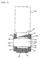
Fig. 2 is a sectional view taken along the line A-A ofFig. 1 . -
Fig. 3 is a sectional view of a rocker arm bearing apparatus according to an embodiment 2 of the invention. -
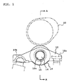
Fig. 1 is a side view of an end-pivot-type rocker arm provided with a rocker arm bearing apparatus according to Embodiment 1 of the invention.Fig. 2 is a sectional view taken along the line A-A ofFig. 1 .
In the drawings, the rocker arm bearing apparatus according to the embodiment of the invention assembled into the rocker arm includes a pair ofopposite sidewalls 12 that constitute a rocker arm body as a bearing holding member, a supportingshaft 14 inserted into and fixed to shaftend insertion holes 12a of the pair ofopposite sidewalls 12, and anouter ring 18 rotatably supported on a raceway portion of a shaft intermediate portion of the supportingshaft 14 through a plurality ofneedle rollers 16. Acam 20 abuts against an outer peripheral surface of theouter ring 18, thereby constituting the rocker arm. - The pair of
opposite sidewalls 12 are made of, for example, steel, and face each other in parallel in the same shape. Alash adjuster receiver 12b and avalve stem receiver 12c are respectively provided on both sides of theopposite sidewalls 12 in their longitudinal direction, and the pair ofopposite sidewalls 12 are configured integrally through thelash adjuster receiver 12b and thevalve stem receiver 12c.
The shaftend insertion holes 12a formed in the pair ofopposite sidewalls 12, respectively, axially pass through theopposite sidewalls 12 with the same fixed hole diameter.
Further, the supportingshaft 14 is made of steel, and although the type of the steel is not particularly limited, steel, such as SUS, SUJ, or SKH, is preferable.
Shaft ends 14a of the supportingshaft 14 are inserted into the shaftend insertion holes 12a of the pair ofopposite sidewalls 12, and theouter ring 18 is rotatably and externally fitted on and supported by the shaftintermediate portion 14b between the pair ofopposite sidewalls 12 through the plurality ofneedle rollers 16 as rolling elements that are made of, for example, steel. Thecam 20 abuts against the outer peripheral surface of theouter ring 18. - Next, a method of manufacturing the rocker arm bearing apparatus according to an embodiment 1 of the invention will be described.
First, an assembly in which theouter ring 18 is rotatably assembled on a rubber shaft having such length that the rubber shaft enters a gap between the pair ofopposite sidewalls 12, the same diameter as the supportingshaft 14, and a width that is below the width of theouter ring 18, through the plurality ofneedle rollers 16, is formed.
Next, the assembly is interposed between the pair ofopposite sidewalls 12, and both ends of the rubber shaft is matched with the shaftend insertion holes 12a of the pair ofopposite sidewalls 12.
Thereafter, the supportingshaft 14 is inserted from the shaftend insertion hole 12a of oneopposite sidewall 12, and the rubber shaft is made to gradually jump out of the shaftend insertion hole 12a of the otheropposite sidewall 12. When the tip of the supportingshaft 14 arrived at the shaftend insertion holes 12a of the otheropposite sidewall 12, the supportingshaft 14 can finally be inserted into the shaftend insertion holes 12a of the pair ofopposite sidewalls 12 instead of the rubber shaft, and theouter ring 18 can be rotatably assembled to the supportingshaft 14 through the plurality ofneedle rollers 16. - After such insertion of the supporting
shaft 14 into the shaftend insertion holes 12a, as shown inFig. 2 , a rocker arm bearing assembly is assembled by fixedly caulking end faces of the shaft ends of the supportingshaft 14 to inner peripheral edges of the shaftend insertion holes 12a. The caulked portion is denoted byreference numeral 24.
The whole rocker arm bearing assembly that is assembled in this way is typically subjected to quenching heat treatment, such as quenching and the following tempering, under vacuum or an atmosphere of inert gas, such as argon gas, whereby the rocker arm bearing apparatus as a product is completed.
In addition, in a case where scales have adhered to the rocker arm bearing apparatus, they can be removed by performing chemical treatment, such as acid cleaning, after heat treatment. - According to the embodiment 1, after insertion of the supporting
shaft 14 including the plurality ofneedle rollers 16 and theouter ring 18 into the shaftend insertion holes 12a of the pair ofopposite sidewalls 12, as shown inFig. 2 , a rocker arm bearing assembly is assembled by fixedly caulking the end faces of theshaft ends 14a of the supportingshaft 14 to the inner peripheral edges of the shaftend insertion holes 12a. Then, the whole rocker arm bearing assembly that is assembled in this way is typically subjected to heat treatment including normal quenching and tempering, under an atmosphere of inert gas, such as argon gas, whereby the rocker arm bearing apparatus is completed. Thus, it is possible to dispense with complicated and time-consuming high-frequency quenching unlike the prior art, it is possible to simplify a quenching process, and it is possible to efficiently assemble the rocker arm bearing apparatus. -
Fig. 3 is a sectional view of a rocker arm bearing apparatus according to an embodiment 2 of the invention.
In the embodiment 2, the same components as those of the above Embodiment 1 are denoted by the same reference numerals, and the description of the duplicate components is omitted.
This Embodiment 2 is different from Embodiment 1 in attaching the supportingshaft 14 to the pair ofopposite sidewalls 12.
That is, in the above Embodiment 1, the rocker arm bearing assembly is assembled by fixedly caulking the end faces of theshaft ends 14a of the supportingshaft 14 on the inner peripheral edges of the shaftend insertion holes 12a. However, in this Embodiment 2, after insertion of the supportingshaft 14 into the shaftend insertion holes 12a of the pair ofopposite sidewalls 12, as shown inFig. 3 , the rocker arm bearing assembly is assembled by fixedly welding (34) the inner peripheral edges of the shaftend insertion holes 12a, and the end face outer edges of the shaft ends 14a of the supportingshaft 14 to each other. Then, the whole rocker arm bearing assembly that is assembled in this way is typically subjected to heat treatment including normal quenching and tempering, under vacuum or an atmosphere of inert gas, such as argon gas, whereby the rocker arm bearing apparatus as a product is completed.
In addition, in a case where scales have adhered to the rocker arm bearing apparatus, they can be removed by performing chemical treatment, such as acid cleaning, or mechanical treatment, such as shot blasting, after heat treatment. - Like this Embodiment 2, after insertion of the supporting
shaft 14 including the plurality ofneedle rollers 16 and theouter ring 18 into the shaftend insertion holes 12a of the pair ofopposite sidewalls 12, as shown inFig. 3 , the rocker arm bearing assembly is assembled by fixedly welding (34) the whole periphery between the inner peripheral edges of the shaftend insertion holes 12a and the end face outer edges of the shaft ends 14a of the supportingshaft 14. Then, the whole rocker arm bearing assembly that is assembled in this way is typically subjected to heat treatment including normal quenching and tempering, under an atmosphere of inert gas, such as argon gas, whereby the rocker arm bearing apparatus is completed. Thus, it is possible to dispense with complicated and time-consuming high-frequency quenching unlike the prior art, it is possible to simplify a quenching process, and it is possible to efficiently assemble the rocker arm bearing apparatus.
Further, in the above embodiment, the pair ofopposite sidewalls 12 and the supportingshaft 14 are fixed by welding (34). Thus, it is not necessary to take into consideration occurrence of deformation in the supportingshaft 14 by caulking, and it is possible to efficiently assemble the rocker arm bearing apparatus. - In addition, in this embodiment 2, the whole periphery between the inner peripheral edges of the shaft
end insertion holes 12a and the end face outer edges of the shaft ends 14a of the supportingshaft 14 is fixedly welded (34). However, the whole periphery may not be welded (34) if sufficient joining strength is guaranteed.
Although normal quenching is shown as quenching heat treatment on the rocker arm bearing assembly in the above Embodiments 1 and 2, it is needless to say that other quenching heat treatment, such as carburizing or carbonitriding, can be applied. Further, although, in the embodiments, the outer ring is rotatably held by the shaft through the rolling elements, the outer ring may be directly rotatably held by the shaft to slide contact therewith without using the rolling elements.
Further, the rocker arm bearing apparatus of the above Embodiments 1 and 2 can also be applied to a center-pivot-type rocker arm.
Claims (3)
- A method of manufacturing a rocker arm bearing apparatus that comprises: a pair of opposite sidewalls (12) including shaft end insertion holes (12 a), respectively; a supporting shaft (14) that includes a raceway portion on a intermediate portion (14 b) thereof and opposite shaft ends (14 a) fixed to inner peripheral edges of the shaft end insertion holes (12 a), respectively; and an outer ring (18) rotatably supported on the raceway portion through a plurality of rolling elements (16) or directly, the method comprising:inserting the opposite shaft ends (14 a) into the shaft end insertion holes (12 a), respectively; andfixing the shaft ends (14 a) to the inner peripheral edges of the shaft end insertion holes (12 a) to form a rocker arm bearing assembly in which the shaft ends (14 a) are fixed to the inner peripheral edges of the shaft end insertion holes (12 a) and the outer ring (18) is rotatably supported on the raceway portion through the plurality of rolling elements (16) or directly;characterized in performing quenching heat treatment on a whole of the rocker arm bearing assembly.
- The method according to claim 1, wherein the shaft ends (14 a) are fixed to the inner peripheral edges of the shaft end insertion holes (12 a) by caulking or welding.
- The method according to claim 1, wherein the quenching heat treatment is performed under vacuum or an atmosphere of inert gas.
Applications Claiming Priority (1)
| Application Number | Priority Date | Filing Date | Title |
|---|---|---|---|
| JP2007044342A JP2008208871A (en) | 2007-02-23 | 2007-02-23 | Rocker arm bearing manufacturing method |
Publications (3)
| Publication Number | Publication Date |
|---|---|
| EP1961925A2 EP1961925A2 (en) | 2008-08-27 |
| EP1961925A3 EP1961925A3 (en) | 2010-07-28 |
| EP1961925B1 true EP1961925B1 (en) | 2011-09-28 |
Family
ID=39445824
Family Applications (1)
| Application Number | Title | Priority Date | Filing Date |
|---|---|---|---|
| EP08003191A Expired - Fee Related EP1961925B1 (en) | 2007-02-23 | 2008-02-21 | Manufacturing method of rocker arm and rocker arm roller |
Country Status (3)
| Country | Link |
|---|---|
| US (1) | US7678206B2 (en) |
| EP (1) | EP1961925B1 (en) |
| JP (1) | JP2008208871A (en) |
Family Cites Families (14)
| Publication number | Priority date | Publication date | Assignee | Title |
|---|---|---|---|---|
| JP3508557B2 (en) | 1998-07-14 | 2004-03-22 | 三菱ふそうトラック・バス株式会社 | Roller device |
| JP2002139067A (en) * | 2000-11-06 | 2002-05-17 | Nsk Ltd | Manufacturing method of shell type needle roller bearing |
| JP2003056315A (en) * | 2001-08-22 | 2003-02-26 | Ntn Corp | Roller-equipped cam follower |
| JP2003206708A (en) * | 2002-01-16 | 2003-07-25 | Ntn Corp | Cam follower with roller |
| JP2003240103A (en) | 2002-02-20 | 2003-08-27 | Koyo Seiko Co Ltd | Cam follower |
| JP2003314665A (en) * | 2002-04-25 | 2003-11-06 | Koyo Seiko Co Ltd | Cam follower |
| JP2003328706A (en) | 2002-05-17 | 2003-11-19 | Ntn Corp | Rocker arm and its bearing |
| JP2003343695A (en) * | 2002-05-28 | 2003-12-03 | Koyo Seiko Co Ltd | Cam follower |
| JP4120358B2 (en) * | 2002-11-06 | 2008-07-16 | 株式会社ジェイテクト | Shaft body for cam follower |
| JP4486411B2 (en) * | 2003-06-05 | 2010-06-23 | Ntn株式会社 | Cam follower with roller |
| JP2006138373A (en) * | 2004-11-11 | 2006-06-01 | Jtekt Corp | Bearing device and assembly method thereof |
| JP2006144848A (en) * | 2004-11-17 | 2006-06-08 | Jtekt Corp | Rocker arm bearing |
| JP4581843B2 (en) * | 2005-05-26 | 2010-11-17 | 日本精工株式会社 | Method for manufacturing rolling ring bearing ring |
| US20070125416A1 (en) * | 2005-12-07 | 2007-06-07 | Kabushiki Kaisha Toshiba | Thermoelectric material and thermoelectric conversion device using same |
-
2007
- 2007-02-23 JP JP2007044342A patent/JP2008208871A/en active Pending
-
2008
- 2008-02-21 US US12/071,491 patent/US7678206B2/en not_active Expired - Fee Related
- 2008-02-21 EP EP08003191A patent/EP1961925B1/en not_active Expired - Fee Related
Also Published As
| Publication number | Publication date |
|---|---|
| JP2008208871A (en) | 2008-09-11 |
| EP1961925A2 (en) | 2008-08-27 |
| US7678206B2 (en) | 2010-03-16 |
| EP1961925A3 (en) | 2010-07-28 |
| US20080202640A1 (en) | 2008-08-28 |
Similar Documents
| Publication | Publication Date | Title |
|---|---|---|
| US5848846A (en) | Shell type needle roller bearing and method of producing the same | |
| US8146340B2 (en) | Link chain | |
| EP1657458B1 (en) | Bearing apparatus and method of assembling the same | |
| EP1961584B1 (en) | Bearing apparatus for wheel | |
| EP1378676B1 (en) | Thrust needle roller bearing and method for manufacture thereof | |
| EP1961925B1 (en) | Manufacturing method of rocker arm and rocker arm roller | |
| JP3073937B2 (en) | Manufacturing method of shell type needle roller bearing | |
| US20060078243A1 (en) | Bearing device and supporting shaft for bearing device | |
| JPH0742744A (en) | Roller bearing | |
| US9618047B2 (en) | Bearing support point with at least one axial bearing | |
| JP4143757B2 (en) | Manufacturing method of shell type roller bearing | |
| JP2000320646A (en) | Cam follower | |
| JP2006046325A (en) | Lever-type cam follower | |
| JP2584333Y2 (en) | Cam follower device | |
| JP3467766B2 (en) | Assembled camshaft | |
| JP4421334B2 (en) | bearing | |
| US20090199795A1 (en) | Camshaft and method for manufacturing a camshaft | |
| JPH08312620A (en) | Assembly construction of shaft member | |
| JP4042666B2 (en) | Rocker arm | |
| JPH0589942U (en) | Bearing device | |
| JP2007120714A (en) | Rolling bearing unit for wheel support | |
| JPH0592403U (en) | Cam follower device | |
| JP3905432B2 (en) | Thrust needle roller bearing and manufacturing method thereof | |
| JPH1038056A (en) | Pulley | |
| JPH11182541A (en) | Shell type roller bearing |
Legal Events
| Date | Code | Title | Description |
|---|---|---|---|
| PUAI | Public reference made under article 153(3) epc to a published international application that has entered the european phase |
Free format text: ORIGINAL CODE: 0009012 |
|
| AK | Designated contracting states |
Kind code of ref document: A2 Designated state(s): AT BE BG CH CY CZ DE DK EE ES FI FR GB GR HR HU IE IS IT LI LT LU LV MC MT NL NO PL PT RO SE SI SK TR |
|
| AX | Request for extension of the european patent |
Extension state: AL BA MK RS |
|
| PUAL | Search report despatched |
Free format text: ORIGINAL CODE: 0009013 |
|
| AK | Designated contracting states |
Kind code of ref document: A3 Designated state(s): AT BE BG CH CY CZ DE DK EE ES FI FR GB GR HR HU IE IS IT LI LT LU LV MC MT NL NO PL PT RO SE SI SK TR |
|
| AX | Request for extension of the european patent |
Extension state: AL BA MK RS |
|
| RIC1 | Information provided on ipc code assigned before grant |
Ipc: B21K 1/20 20060101ALI20100623BHEP Ipc: C21D 1/00 20060101ALI20100623BHEP Ipc: F16C 13/00 20060101ALI20100623BHEP Ipc: F01L 1/18 20060101AFI20080605BHEP |
|
| 17P | Request for examination filed |
Effective date: 20101007 |
|
| GRAP | Despatch of communication of intention to grant a patent |
Free format text: ORIGINAL CODE: EPIDOSNIGR1 |
|
| AKX | Designation fees paid |
Designated state(s): DE FR |
|
| RIC1 | Information provided on ipc code assigned before grant |
Ipc: B21K 1/20 20060101ALI20110225BHEP Ipc: C21D 1/00 20060101ALI20110225BHEP Ipc: F16C 13/00 20060101ALI20110225BHEP Ipc: F01L 1/18 20060101AFI20110225BHEP |
|
| GRAC | Information related to communication of intention to grant a patent modified |
Free format text: ORIGINAL CODE: EPIDOSCIGR1 |
|
| GRAS | Grant fee paid |
Free format text: ORIGINAL CODE: EPIDOSNIGR3 |
|
| GRAA | (expected) grant |
Free format text: ORIGINAL CODE: 0009210 |
|
| AK | Designated contracting states |
Kind code of ref document: B1 Designated state(s): DE FR |
|
| REG | Reference to a national code |
Ref country code: DE Ref legal event code: R096 Ref document number: 602008010072 Country of ref document: DE Effective date: 20111201 |
|
| PGFP | Annual fee paid to national office [announced via postgrant information from national office to epo] |
Ref country code: FR Payment date: 20120201 Year of fee payment: 5 |
|
| PGFP | Annual fee paid to national office [announced via postgrant information from national office to epo] |
Ref country code: DE Payment date: 20120229 Year of fee payment: 5 |
|
| PLBE | No opposition filed within time limit |
Free format text: ORIGINAL CODE: 0009261 |
|
| STAA | Information on the status of an ep patent application or granted ep patent |
Free format text: STATUS: NO OPPOSITION FILED WITHIN TIME LIMIT |
|
| 26N | No opposition filed |
Effective date: 20120629 |
|
| REG | Reference to a national code |
Ref country code: DE Ref legal event code: R097 Ref document number: 602008010072 Country of ref document: DE Effective date: 20120629 |
|
| REG | Reference to a national code |
Ref country code: FR Ref legal event code: ST Effective date: 20131031 |
|
| REG | Reference to a national code |
Ref country code: DE Ref legal event code: R119 Ref document number: 602008010072 Country of ref document: DE Effective date: 20130903 |
|
| PG25 | Lapsed in a contracting state [announced via postgrant information from national office to epo] |
Ref country code: FR Free format text: LAPSE BECAUSE OF NON-PAYMENT OF DUE FEES Effective date: 20130228 Ref country code: DE Free format text: LAPSE BECAUSE OF NON-PAYMENT OF DUE FEES Effective date: 20130903 |