EP1961922A2 - Control of variable pitch angle blades - Google Patents
Control of variable pitch angle blades Download PDFInfo
- Publication number
- EP1961922A2 EP1961922A2 EP08075112A EP08075112A EP1961922A2 EP 1961922 A2 EP1961922 A2 EP 1961922A2 EP 08075112 A EP08075112 A EP 08075112A EP 08075112 A EP08075112 A EP 08075112A EP 1961922 A2 EP1961922 A2 EP 1961922A2
- Authority
- EP
- European Patent Office
- Prior art keywords
- pivot
- ball bearing
- blade
- variable pitch
- pitch angle
- Prior art date
- Legal status (The legal status is an assumption and is not a legal conclusion. Google has not performed a legal analysis and makes no representation as to the accuracy of the status listed.)
- Granted
Links
- 230000000295 complement effect Effects 0.000 claims abstract description 5
- 238000005219 brazing Methods 0.000 claims description 2
- 239000002985 plastic film Substances 0.000 claims description 2
- 229920006255 plastic film Polymers 0.000 claims description 2
- 238000003466 welding Methods 0.000 claims description 2
- 239000000463 material Substances 0.000 description 4
- 239000011368 organic material Substances 0.000 description 3
- 238000002485 combustion reaction Methods 0.000 description 2
- 239000004642 Polyimide Substances 0.000 description 1
- 230000009471 action Effects 0.000 description 1
- 238000012550 audit Methods 0.000 description 1
- 230000015556 catabolic process Effects 0.000 description 1
- 229910010293 ceramic material Inorganic materials 0.000 description 1
- 230000008859 change Effects 0.000 description 1
- 239000011248 coating agent Substances 0.000 description 1
- 238000000576 coating method Methods 0.000 description 1
- 238000013016 damping Methods 0.000 description 1
- 238000006731 degradation reaction Methods 0.000 description 1
- 230000001627 detrimental effect Effects 0.000 description 1
- 239000007789 gas Substances 0.000 description 1
- 239000000314 lubricant Substances 0.000 description 1
- 238000000034 method Methods 0.000 description 1
- 230000004048 modification Effects 0.000 description 1
- 238000012986 modification Methods 0.000 description 1
- 229920001721 polyimide Polymers 0.000 description 1
- 229920001296 polysiloxane Polymers 0.000 description 1
- 238000005086 pumping Methods 0.000 description 1
- 230000009467 reduction Effects 0.000 description 1
- 229920002379 silicone rubber Polymers 0.000 description 1
- 230000001360 synchronised effect Effects 0.000 description 1
Images

Classifications
-
- F—MECHANICAL ENGINEERING; LIGHTING; HEATING; WEAPONS; BLASTING
- F01—MACHINES OR ENGINES IN GENERAL; ENGINE PLANTS IN GENERAL; STEAM ENGINES
- F01D—NON-POSITIVE DISPLACEMENT MACHINES OR ENGINES, e.g. STEAM TURBINES
- F01D17/00—Regulating or controlling by varying flow
- F01D17/10—Final actuators
- F01D17/12—Final actuators arranged in stator parts
- F01D17/14—Final actuators arranged in stator parts varying effective cross-sectional area of nozzles or guide conduits
- F01D17/16—Final actuators arranged in stator parts varying effective cross-sectional area of nozzles or guide conduits by means of nozzle vanes
- F01D17/162—Final actuators arranged in stator parts varying effective cross-sectional area of nozzles or guide conduits by means of nozzle vanes for axial flow, i.e. the vanes turning around axes which are essentially perpendicular to the rotor centre line
-
- F—MECHANICAL ENGINEERING; LIGHTING; HEATING; WEAPONS; BLASTING
- F02—COMBUSTION ENGINES; HOT-GAS OR COMBUSTION-PRODUCT ENGINE PLANTS
- F02C—GAS-TURBINE PLANTS; AIR INTAKES FOR JET-PROPULSION PLANTS; CONTROLLING FUEL SUPPLY IN AIR-BREATHING JET-PROPULSION PLANTS
- F02C9/00—Controlling gas-turbine plants; Controlling fuel supply in air- breathing jet-propulsion plants
- F02C9/16—Control of working fluid flow
- F02C9/20—Control of working fluid flow by throttling; by adjusting vanes
- F02C9/22—Control of working fluid flow by throttling; by adjusting vanes by adjusting turbine vanes
-
- F—MECHANICAL ENGINEERING; LIGHTING; HEATING; WEAPONS; BLASTING
- F04—POSITIVE - DISPLACEMENT MACHINES FOR LIQUIDS; PUMPS FOR LIQUIDS OR ELASTIC FLUIDS
- F04D—NON-POSITIVE-DISPLACEMENT PUMPS
- F04D29/00—Details, component parts, or accessories
- F04D29/40—Casings; Connections of working fluid
- F04D29/52—Casings; Connections of working fluid for axial pumps
- F04D29/54—Fluid-guiding means, e.g. diffusers
- F04D29/56—Fluid-guiding means, e.g. diffusers adjustable
- F04D29/563—Fluid-guiding means, e.g. diffusers adjustable specially adapted for elastic fluid pumps
-
- F—MECHANICAL ENGINEERING; LIGHTING; HEATING; WEAPONS; BLASTING
- F05—INDEXING SCHEMES RELATING TO ENGINES OR PUMPS IN VARIOUS SUBCLASSES OF CLASSES F01-F04
- F05D—INDEXING SCHEME FOR ASPECTS RELATING TO NON-POSITIVE-DISPLACEMENT MACHINES OR ENGINES, GAS-TURBINES OR JET-PROPULSION PLANTS
- F05D2260/00—Function
- F05D2260/70—Adjusting of angle of incidence or attack of rotating blades
- F05D2260/74—Adjusting of angle of incidence or attack of rotating blades by turning around an axis perpendicular the rotor centre line
-
- F—MECHANICAL ENGINEERING; LIGHTING; HEATING; WEAPONS; BLASTING
- F05—INDEXING SCHEMES RELATING TO ENGINES OR PUMPS IN VARIOUS SUBCLASSES OF CLASSES F01-F04
- F05D—INDEXING SCHEME FOR ASPECTS RELATING TO NON-POSITIVE-DISPLACEMENT MACHINES OR ENGINES, GAS-TURBINES OR JET-PROPULSION PLANTS
- F05D2260/00—Function
- F05D2260/70—Adjusting of angle of incidence or attack of rotating blades
- F05D2260/79—Bearing, support or actuation arrangements therefor
Definitions
- the present invention relates to the control of blades with variable pitch angle, in particular a control device of a blade pivot at variable pitch angle in a turbomachine compressor.
- An aviation turbine engine typically comprises a compressor, a combustion chamber and a turbine.
- the role of the turbine is to ensure the rotational drive of the compressor by taking a portion of the pressure energy of the hot gases leaving the combustion chamber and converting it into mechanical energy.
- An axial compressor consists of a rotating part, the rotor, of a fixed part, the stator, and an envelope, the housing, the stator and the housing being integral with one another.
- the rotor comprises a drum constituted by an assembly of several discs on which are fixed blades in a circumferential row.
- the stator is constituted by a plurality of vanes fixed on the housing or on circumferential row shells. Each row of stationary blades of the stator, called rectifiers, constitutes a rectifier.
- a row of moving blades and a row of stationary vanes form a compressor stage.
- one or more rows of straightening vanes may be variable pitch angle, that is to say that the angle of attack of these blades varies depending on flight conditions.
- Known devices for controlling the variable pitch angle of the blade pivots often include a control ring surrounding a casing of the turbomachine and a plurality of levers or rods.
- Each lever comprises, on the one hand, a first end mounted rigidly on a pivot integral with a blade whose axis of rotation is oriented radially with respect to the axis of revolution of the turbomachine and, on the other hand, a second end connected to the control ring.
- the synchronized modification of the angular position of the blades is obtained by the rotation of the control ring around the axis of the turbomachine.
- Such a system is illustrated on the figure 1 of the document US 5024580 .
- the pivot of a blade is disposed in a bore usually made in the housing and oriented radially relative to the axis of the turbomachine.
- the movements of the control ring, the lever and the pivot for the variation of the wedging angle expose the contact zones of these parts to degradations, which are accentuated by the vibrations of the turbomachine.
- the most important wear is noted between the pivot and the bore due to the matt pressures which is detrimental to the mechanical strength of the parts and therefore to their service life.
- a partial or total loss of accuracy in the wedge angle of the blades impairs the proper functioning of the turbomachine and in particular its performance.
- cylindrical bushings acting bearing and dry lubricant.
- Examples of cylindrical bushings are illustrated in the various figures of the document EP 1500791 .
- the materials used for these cylindrical sockets are generally from two families: organic and non-organic. When temperature conditions permit, that is, below about 300 °, organic materials are generally employed. Beyond this, non-organic materials are preferred.
- the main object of the present invention is to provide a device for controlling a blade pivot with a variable pitch angle with an improved service life and making it possible to reduce the loads applied to the contact zones.
- Another object of the invention is to reduce leaks between the pivot and the bore. These leaks reduce the overall efficiency of the turbomachine and can even damage the control means located outside the compressor.
- the invention relates in particular to a control device for a variable pitch angle blade pivot comprising a control lever and a pivot having a lower end and an upper end, said upper end being connected to the lever of ordered.
- this device comprises two ball bearings, a first ball bearing being disposed at the lower end of the pivot and a second ball bearing being disposed at the upper end of the pivot.
- the invention also relates to a compressor comprising such a stator and a turbomachine comprising said compressor.
- the device proposed by the invention makes it possible to reduce substantially the charges applied to the contact zones. It then becomes possible to use a larger range of materials capable of withstanding wear.
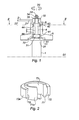
- the figure 1 represents a device for controlling the angle of registration of a blade 1 along an axis (X) oriented radially with respect to the axis of revolution (Y) of a turbomachine casing.
- a pivot 3 is located in the extension of a blade 1 and oriented along the same axis (X).
- the blade 1 and the pivot 3 can be separated by a plate 11, reconstituting a portion of the aerodynamic stream situated in the vicinity, arranged in a countersink 51 of the casing 5.
- the bore 4 may comprise at each of its ends 41 and 42 a counterbore 44, that is to say a cylindrical housing, intended to accommodate each ball bearing 7.
- the fixing of the ball bearing 7 in the bore 4 can be made by shrinking , welding, brazing or any other equivalent method.
- the fixing of the ball bearing 7 is carried out prior to assembly of the blades 1.
- the pivot 3 comprises, at its second end 32, a threaded rod 33 intended to cooperate with a nut 34 and a washer 35 to connect it rigidly to a first end 21 of a control lever 2.
- a second end 22 of the lever of control 2 is connected to a control ring (not shown).
- a second washer 6 can also be arranged between the control lever 2 and the second upper end 42 of the bore 4.
- Other connection means between the pivot 3 and the control lever 2 are possible without questioning the principle of the invention.
- the rotation of the pivot 3 along the axis (X) makes it possible to vary the wedging angle of the blade 1.
- the device comprises two ball bearings 7, a first ball bearing 7 being disposed at the lower end 31 of the pivot 3 and a second ball bearing 7 being disposed at the upper end 32 of the pivot 3 .
- a spherical bearing 7 is shown in more detail on the figure 2 . It comprises an inner ring 71, having a cylindrical inner surface 71i and a spherical outer surface 71e, and an outer ring 72, having a spherical inner surface 72i and a cylindrical outer surface 72e.
- the rings 71 and 72 form, thanks to their spherical contact surfaces 71 e and 72 i, a ball joint, also called spherical connection, that is to say a connection allowing three rotational movements along three different axes.
- the pivot 3 passes through the ball bearing 7 and is in contact with the cylindrical inner surface 71 i of the inner ring 71.
- the ball bearing 7 guides the pivot 3 in rotation along the axis (X).
- the spherical bearing 7 may be made of an organic material, such as for example polyimide; it can also be made of a metallic or ceramic material.
- a section made along line II-II of the figure 1 represents by several examples, 3A, 3B, 3C, 3D and 3E, the connection between the ball bearing 7 and the pivot.
- the rotational locking is obtained by the fact that the pivot 3 comprises at least one flat portion 36 on its outer surface, the inner shape of the inner ring 71 being complementary.
- the locking in rotation is obtained by the fact that the pivot 3 has a form of tenon 37 and that the inner shape of the inner ring 71 has a mortise shape 37.
- the locking in rotation is obtained by the fact that the pivot 3 and the inner surface of the inner ring 71 of the ball bearing 7 have complementary square-shaped sections.
- a damping or adhering means 73 may be interposed between these two parts, for example a plastic film such as RTV (Room Temperature Vulcanizing) type silicone elastomer, that is, a cold-curable silicone. It also avoids wear on the pivot 3.
- RTV Room Temperature Vulcanizing
- the cylindrical sleeve is replaced by a spherical bearing, having an inner ring, whose inner diameter is 7.94 mm and the outer diameter is 14.27 mm, and an outer ring whose outer diameter is 19.05 mm, with a clearance of 0.018 mm between the two rings, it was found by calculation that, under the same operating conditions, the contact pressure is 40 MPa. Therefore, thanks to the invention, a contact pressure is obtained at least 2 times lower and even up to 4 times lower under the most unfavorable conditions observed in the test.
- variable pitch blade control device using a ball bearing 7 In a variable pitch blade control device using a ball bearing 7 according to the invention, leakage is less important than in a variable pitch blade control device using a cylindrical sleeve. This is explained by the fact that the existing game between inner ring 71 and the outer ring 72 of a ball bearing 7 is very small. The invention therefore also reduces leaks between the pivot and the bore. The efficiency of the turbomachine is thus improved.
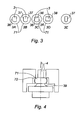
- the invention also relates to a compressor 91 comprising such a stator and a turbomachine 9 comprising such a compressor 91, as shown in FIG. figure 5 .
Abstract
Description
La présente invention concerne la commande des aubes à angle de calage variable, notamment un dispositif de commande d'un pivot d'aube à angle de calage variable dans un compresseur de turbomachine.The present invention relates to the control of blades with variable pitch angle, in particular a control device of a blade pivot at variable pitch angle in a turbomachine compressor.
Une turbomachine aéronautique comporte classiquement un compresseur, une chambre de combustion et une turbine. Le rôle de la turbine est d'assurer l'entraînement en rotation du compresseur en prélevant une partie de l'énergie de pression des gaz chauds sortant de la chambre de combustion et en la transformant en énergie mécanique.An aviation turbine engine typically comprises a compressor, a combustion chamber and a turbine. The role of the turbine is to ensure the rotational drive of the compressor by taking a portion of the pressure energy of the hot gases leaving the combustion chamber and converting it into mechanical energy.
Un compresseur axial est constitué d'une partie tournante, le rotor, d'une partie fixe, le stator, et d'une enveloppe, le carter, le stator et le carter étant solidaires l'un de l'autre. Le rotor comprend un tambour constitué par un assemblage de plusieurs disques sur lesquels sont fixées des aubes mobiles en rangée circonférentielle. Le stator est constitué d'une pluralité d'aubes fixées sur le carter ou sur des viroles en rangée circonférentielle. Chaque rangée d'aubes fixes du stator, dites redresseuses, constitue un redresseur. Une rangée d'aubes mobiles et une rangée d'aubes fixes forment un étage de compresseur.An axial compressor consists of a rotating part, the rotor, of a fixed part, the stator, and an envelope, the housing, the stator and the housing being integral with one another. The rotor comprises a drum constituted by an assembly of several discs on which are fixed blades in a circumferential row. The stator is constituted by a plurality of vanes fixed on the housing or on circumferential row shells. Each row of stationary blades of the stator, called rectifiers, constitutes a rectifier. A row of moving blades and a row of stationary vanes form a compressor stage.
Dans un compresseur, pour optimiser le rendement de la turbomachine et la marge au pompage selon le régime, une ou plusieurs rangées d'aubes redresseuses peuvent être à angle de calage variable, c'est-à-dire que l'angle d'attaque de ces aubes varie en fonction des conditions de vol.In a compressor, to optimize the performance of the turbomachine and the pumping margin according to the regime, one or more rows of straightening vanes may be variable pitch angle, that is to say that the angle of attack of these blades varies depending on flight conditions.
Les dispositifs connus pour la commande des pivots d'aube à angle de calage variable comportent souvent un anneau de commande entourant un carter de la turbomachine et une pluralité de leviers ou biellettes. Chaque levier comporte, d'une part, une première extrémité montée rigidement sur un pivot solidaire d'une aube dont l'axe de rotation est orienté radialement par rapport à l'axe de révolution de la turbomachine et, d'autre part, une deuxième extrémité reliée à l'anneau de commande. La modification synchronisée de la position angulaire des aubes est obtenue par la rotation de l'anneau de commande autour de l'axe de la turbomachine. Un tel système est illustré sur la
Le pivot d'une aube est disposé dans un alésage habituellement réalisé dans le carter et orienté radialement par rapport à l'axe de la turbomachine. Les mouvements de l'anneau de commande, du levier et du pivot pour la variation de l'angle de calage exposent les zones de contact de ces pièces à des dégradations, lesquelles sont accentuées par les vibrations de la turbomachine. Les usures les plus importantes sont constatées entre le pivot et l'alésage en raison des pressions de matage ce qui est préjudiciable à la tenue mécanique des pièces et donc à leur durée de vie. De plus, une perte de précision partielle ou totale dans l'angle calage des aubes nuit au bon fonctionnement de la turbomachine et notamment à son rendement.The pivot of a blade is disposed in a bore usually made in the housing and oriented radially relative to the axis of the turbomachine. The movements of the control ring, the lever and the pivot for the variation of the wedging angle expose the contact zones of these parts to degradations, which are accentuated by the vibrations of the turbomachine. The most important wear is noted between the pivot and the bore due to the matt pressures which is detrimental to the mechanical strength of the parts and therefore to their service life. In addition, a partial or total loss of accuracy in the wedge angle of the blades impairs the proper functioning of the turbomachine and in particular its performance.
Pour réduire l'usure entre le pivot et l'alésage, il est connu d'interposer entre ces pièces une ou plusieurs douilles cylindriques jouant le rôle de palier et de lubrifiant sec. Des exemples de douilles cylindriques sont illustrées sur les différentes figures du document
Pour améliorer l'efficacité de ces douilles cylindriques, de nombreuses solutions en terme de matériau ou de revêtement ont été proposées et décrites notamment dans les documents
Il est également connu des documents
La présente invention a pour objectif principal de proposer un dispositif de commande d'un pivot d'aube à angle de calage variable avec une durée de vie améliorée et permettant de réduire les charges appliquées sur les zones de contact.The main object of the present invention is to provide a device for controlling a blade pivot with a variable pitch angle with an improved service life and making it possible to reduce the loads applied to the contact zones.
Un autre objectif de l'invention est de réduire les fuites entre le pivot et l'alésage. Ces fuites réduisent le rendement global de la turbomachine et peuvent même endommager les moyens de régulation situés à l'extérieur du compresseur.Another object of the invention is to reduce leaks between the pivot and the bore. These leaks reduce the overall efficiency of the turbomachine and can even damage the control means located outside the compressor.
A cet effet, l'invention concerne notamment un dispositif de commande d'un pivot d'aube à angle de calage variable comportant un levier de commande et un pivot comportant une extrémité inférieure et une extrémité supérieure, ladite extrémité supérieure étant reliée au levier de commande. Selon l'invention, ce dispositif comprend deux paliers à rotule, un premier palier à rotule étant disposé à l'extrémité inférieure du pivot et un second palier à rotule étant disposé à l'extrémité supérieure du pivot.For this purpose, the invention relates in particular to a control device for a variable pitch angle blade pivot comprising a control lever and a pivot having a lower end and an upper end, said upper end being connected to the lever of ordered. According to the invention, this device comprises two ball bearings, a first ball bearing being disposed at the lower end of the pivot and a second ball bearing being disposed at the upper end of the pivot.
L'invention concerne également un stator comportant un carter d'axe de révolution (Y) comprenant au moins un alésage réalisé selon un axe radial (X) orienté perpendiculairement audit axe de révolution (Y). Selon l'invention, ce stator comporte en outre :
- au moins un dispositif de commande de pivot d'aube, et
- au moins une aube orientée selon l'axe radial (X) disposée à l'intérieur du carter, ladite aube étant solidaire du pivot par l'extrémité inférieure dudit pivot,
- at least one blade pivot controller, and
- at least one blade oriented along the radial axis (X) disposed inside the housing, said blade being integral with the pivot by the lower end of said pivot,
L'invention se rapporte également à un compresseur comportant un tel stator et une turbomachine comportant ledit compresseur. Avantageusement, le dispositif proposé par l'invention permet de réduire sensiblement les charges appliquées sur les zones de contact. Il devient alors envisageable d'employer une gamme de matériaux plus importante capable de résister à l'usure.The invention also relates to a compressor comprising such a stator and a turbomachine comprising said compressor. Advantageously, the device proposed by the invention makes it possible to reduce substantially the charges applied to the contact zones. It then becomes possible to use a larger range of materials capable of withstanding wear.
D'autres avantages et caractéristiques de l'invention ressortiront à la lecture de description détaillée qui suit en référence aux figures annexées, fournies à titre d'exemples non limitatifs, sur lesquelles :
- la
figure 1 représente un dispositif de commande d'un pivot d'aube à angle de calage variable selon l'invention ; - la
figure 2 représente un palier à rotule ; - la
figure 3 représente une coupe effectuée selon la ligne II-II de lafigure 1 détaillant la liaison entre le palier à rotule et le pivot selon différentesvariantes - la
figure 4 représente un détail d'une variante du dispositif de commande d'un pivot d'aube à angle de calage variable selon l'invention ; et - la
figure 5 représente une turbomachine.
- the
figure 1 represents a control device for a blade pivot variable pitch angle according to the invention; - the
figure 2 represents a spherical bearing; - the
figure 3 represents a section on the line II-II of thefigure 1 detailing the connection between the swivel bearing and the pivot according todifferent variants - the
figure 4 represents a detail of a variant of the control device of a blade pivot variable angle variable according to the invention; and - the
figure 5 represents a turbomachine.
La
Le pivot 3, comportant une extrémité inférieure 31 et une extrémité supérieure 32, est disposé dans un alésage 4, comportant une extrémité inférieure 41 et une extrémité supérieure 42, habituellement réalisé dans le carter 5. A cet effet, l'alésage 4 peut comprendre en chacune de ses extrémités 41 et 42 un lamage 44, c'est-à-dire un logement cylindrique, destiné à accueillir chaque palier à rotule 7. La fixation du palier à rotule 7 dans l'alésage 4 peut s'effectuer par frettage, soudage, brasage ou toute autre méthode équivalente. De préférence, la fixation du palier à rotule 7 s'effectue préalablement au montage des aubes 1.The
Dans le domaine des turbomachines, dans le contexte d'une pièce de révolution, il est courant d'utiliser les termes « supérieure » et « inférieure » à la place, respectivement, de « extérieure » et « intérieure ».In the field of turbomachines, in the context of a piece of revolution, it is common to use the terms "upper" and "lower" instead, respectively, of "outer" and "inner".
Le pivot 3 comporte, à sa seconde extrémité 32, une tige filetée 33 destinée à coopérer avec un écrou 34 et une rondelle 35 pour le relier rigidement à une première extrémité 21 d'un levier de commande 2. Une deuxième extrémité 22 du levier de commande 2 est reliée à un anneau de commande (non représenté). Une seconde rondelle 6 peut également être disposée entre le levier de commande 2 et la seconde extrémité supérieure 42 de l'alésage 4. D'autres moyens de liaison entre le pivot 3 et le levier de commande 2 sont envisageables sans pour autant remettre en cause le principe de l'invention. La rotation du pivot 3 selon l'axe (X) permet de faire varier l'angle de calage de l'aube 1.The
Conformément à l'invention, le dispositif comprend deux paliers à rotule 7, un premier palier à rotule 7 étant disposé à l'extrémité inférieure 31 du pivot 3 et un second palier à rotule 7 étant disposé à l'extrémité supérieure 32 du pivot 3.According to the invention, the device comprises two ball bearings 7, a first ball bearing 7 being disposed at the
Un palier à rotule 7 est représenté plus en détail sur la
Sans que cela soit indispensable, la bague intérieure 71 du palier à rotule 7 et le pivot 3 peuvent être bloqués en rotation l'un par rapport à l'autre. Ce blocage en rotation peut être obtenu de différentes manières. Une coupe effectuée selon la ligne II-II de la
Selon des premiers exemples, illustrés sur les
Selon des deuxièmes exemples, illustrés sur les
Selon un troisième exemple, illustré sur la
Pour limiter les vibrations entre le pivot 3 et la surface intérieure 71 i de la bague intérieure 71 du palier à pivot 7, un moyen d'amortissement ou adhérent 73 peut être interposé entre ces deux pièces, par exemple un film en matière plastique tel que de l'élastomère de silicone de type RTV (Room Temperature Vulcanizing), c'est-à-dire un silicone polymérisable à froid. Il permet également d'éviter les usures sur le pivot 3.To limit the vibrations between the
Une variante applicable à l'invention présentée ci-dessus consiste à munir le pivot 3 d'une extrémité ayant une section à diamètre croissant 39 pour positionner le pivot 3 correctement par rapport au palier à rotule 7 et au carter 5. Cette variante est illustrée sur la
Un jeu suffisant doit être conservé entre la platine 11 de l'aube 1 et le palier à rotule 7 afin que le fonctionnement du dispositif ne soit pas bloqué par un contact entre la platine 11 et le lamage 51 de carter ou la platine 11 et la bague extérieure 72 du palier à rotule 7.Sufficient clearance must be maintained between the
Des calculs ont montré que le remplacement d'une liaison pivot, autorisant un unique mouvement de rotation, par une liaison rotule, autorisant trois mouvements de rotation, permet de réduire les charges appliquées sur les zones de contact. Ces calculs ont été effectués en prenant en considération deux matériaux identiques en contact ayant un coefficient de Poisson de 0,3 et un module d'Young de 200000 Mpa.Calculations have shown that the replacement of a pivot connection, allowing a single rotational movement, by a ball joint, allowing three rotational movements, reduces the loads applied to the contact areas. These calculations were made taking into consideration two identical materials in contact with a Poisson's ratio of 0.3 and a Young's modulus of 200000 MPa.
Dans le cas d'une douille cylindrique disposée autour d'un pivot, correspondant à un contact cylindre intérieur / cylindre extérieur, les valeurs suivantes ont été choisies : diamètre du cylindre intérieur de 15,72 mm et diamètre du cylindre extérieur de 15,612 mm, soit un jeu de 0,108. Le contact s'effectue sur une longueur comprise entre 1 et 4 mm en fonction de l'alignement des pièces, avec un déversement de l'aube, c'est-à-dire une inclinaison de celle-ci par rapport à son axe (X) sous l'action de la force aérodynamique exercée. Dans des conditions extrêmes, par exemple lors du décollage d'un aéronef équipé d'un tel dispositif, il a été constaté par le calcul que la pression de contact varie de 84 à 167 Mpa en fonction de l'alignement de la douille cylindrique.In the case of a cylindrical sleeve arranged around a pivot, corresponding to an inner cylinder / outer cylinder contact, the following values have been chosen: inner cylinder diameter of 15.72 mm and outer cylinder diameter of 15.612 mm, a game of 0.108. The contact takes place over a length of between 1 and 4 mm depending on the alignment of the parts, with a spill of the blade, that is to say an inclination thereof with respect to its axis ( X) under the action of the aerodynamic force exerted. In extreme conditions, for example during take-off of an aircraft equipped with such a device, it has been found by calculation that the contact pressure varies from 84 to 167 MPa depending on the alignment of the cylindrical sleeve.
Dans un alésage légèrement modifié, le remplacement de la douille cylindrique par un palier à rotule, comportant une bague intérieure, dont le diamètre intérieur est de 7,94 mm et le diamètre extérieur est de 14,27 mm, et une bague extérieure dont le diamètre extérieur est de 19,05 mm, avec un jeu de 0,018 mm entre les deux bagues, il a été constaté par le calcul que, dans les mêmes conditions de fonctionnement, la pression de contact est de 40 Mpa. Par conséquent, grâce à l'invention, on obtient une pression de contact au moins 2 fois plus faible et même jusqu'à 4 fois plus faible dans les conditions les plus défavorables observées en essai.In a slightly modified bore, the cylindrical sleeve is replaced by a spherical bearing, having an inner ring, whose inner diameter is 7.94 mm and the outer diameter is 14.27 mm, and an outer ring whose outer diameter is 19.05 mm, with a clearance of 0.018 mm between the two rings, it was found by calculation that, under the same operating conditions, the contact pressure is 40 MPa. Therefore, thanks to the invention, a contact pressure is obtained at least 2 times lower and even up to 4 times lower under the most unfavorable conditions observed in the test.
Dans un dispositif de commande d'aube à calage variable utilisant un palier à rotule 7 selon l'invention, les fuites sont moins importantes que dans un dispositif de commande d'aube à calage variable utilisant une douille cylindrique. Ceci est expliqué par le fait que le jeu existant entre la bague intérieure 71 et la bague extérieure 72 d'un palier à rotule 7 est très faible. L'invention permet donc également de réduire les fuites entre le pivot et l'alésage. Le rendement de la turbomachine est ainsi amélioré.In a variable pitch blade control device using a ball bearing 7 according to the invention, leakage is less important than in a variable pitch blade control device using a cylindrical sleeve. This is explained by the fact that the existing game between
Un autre objet de l'invention concerne également un stator comportant :
un carter 5 d'axe de révolution (Y) comprenant au moinsun alésage 4 réalisé selon un axe radial (X) orienté perpendiculairement audit axe (Y),- au moins un dispositif de commande de pivot d'aube à angle de calage variable, et
- au moins une aube 1 orientée selon l'axe radial (X) disposée à l'intérieur du
carter 5, ladite aube 1 étant solidaire dupivot 3 par l'extrémité inférieure 32dudit pivot 3,
- a
casing 5 of axis of revolution (Y) comprising at least onebore 4 formed along a radial axis (X) oriented perpendicular to said axis (Y), - at least one blade pivot control device with variable pitch angle, and
- at least one blade 1 oriented along the radial axis (X) disposed inside the
housing 5, said blade 1 being integral with thepivot 3 by thelower end 32 of saidpivot 3,
L'invention se rapporte également à un compresseur 91 comportant un tel stator ainsi qu'une turbomachine 9 comportant un tel compresseur 91, tels que représentés sur la
Claims (13)
Applications Claiming Priority (1)
| Application Number | Priority Date | Filing Date | Title |
|---|---|---|---|
| FR0701258A FR2913052B1 (en) | 2007-02-22 | 2007-02-22 | CONTROL OF AUBES WITH VARIABLE SETTING ANGLE |
Publications (3)
| Publication Number | Publication Date |
|---|---|
| EP1961922A2 true EP1961922A2 (en) | 2008-08-27 |
| EP1961922A3 EP1961922A3 (en) | 2010-11-17 |
| EP1961922B1 EP1961922B1 (en) | 2012-01-11 |
Family
ID=38476002
Family Applications (1)
| Application Number | Title | Priority Date | Filing Date |
|---|---|---|---|
| EP08075112A Active EP1961922B1 (en) | 2007-02-22 | 2008-02-13 | Control of variable pitch angle blades |
Country Status (6)
| Country | Link |
|---|---|
| US (1) | US8147187B2 (en) |
| EP (1) | EP1961922B1 (en) |
| JP (1) | JP5126505B2 (en) |
| CA (1) | CA2621730C (en) |
| FR (1) | FR2913052B1 (en) |
| RU (1) | RU2488002C2 (en) |
Cited By (2)
| Publication number | Priority date | Publication date | Assignee | Title |
|---|---|---|---|---|
| EP2808495A1 (en) * | 2013-05-29 | 2014-12-03 | MTU Aero Engines GmbH | Bearing arrangement for an adjustable guide blade |
| EP2620602A3 (en) * | 2012-01-27 | 2016-04-20 | United Technologies Corporation | Variable vane damping assembly, corresponding variable vane assembly and method of damping a variable vane |
Families Citing this family (14)
| Publication number | Priority date | Publication date | Assignee | Title |
|---|---|---|---|---|
| DE102008021683A1 (en) * | 2008-04-30 | 2009-11-05 | Rolls-Royce Deutschland Ltd & Co Kg | Rotating unit for an axial compressor |
| US8568100B2 (en) * | 2008-12-09 | 2013-10-29 | The Boeing Company | Bi-axial compliant bearing |
| DE102008061414B4 (en) * | 2008-12-10 | 2013-01-31 | Hydac Electronic Gmbh | Method for producing an electromagnetic actuating device, in particular for actuating valves, and actuating device produced by the method |
| FR2992376B1 (en) * | 2012-06-25 | 2016-03-04 | Snecma | VARIABLE TIMING BLOWER BY DIFFERENTIAL ROTATION OF BLOWER DISKS |
| US10125789B2 (en) | 2013-02-15 | 2018-11-13 | United Technologies Corporation | Bushing arranged between a body and a shaft, and connected to the body |
| FR3008639B1 (en) * | 2013-07-18 | 2015-08-07 | Snecma | METHOD FOR ASSEMBLING TURBOMACHINE PARTS AND ASSEMBLY IMPLEMENTED THEREIN |
| US10132191B2 (en) * | 2013-08-21 | 2018-11-20 | United Technologies Corporation | Variable area turbine arrangement with secondary flow modulation |
| US9835053B2 (en) * | 2014-02-21 | 2017-12-05 | United Technologies Corporation | Self-lubricating bushings |
| US9970315B2 (en) * | 2015-02-12 | 2018-05-15 | Hamilton Sundstrand Corporation | Movable vane control system |
| DE102017222209A1 (en) * | 2017-12-07 | 2019-06-13 | MTU Aero Engines AG | Guide vane connection and turbomachine |
| DE102018132837A1 (en) * | 2018-12-19 | 2020-06-25 | Herrmann Ultraschalltechnik Gmbh & Co. Kg | Ultrasonic welding system |
| KR102588670B1 (en) * | 2019-01-14 | 2023-10-11 | 한화오션 주식회사 | Device for supporting sonar of underwater moving body |
| US11428113B2 (en) * | 2020-12-08 | 2022-08-30 | General Electric Company | Variable stator vanes with anti-lock trunnions |
| FR3120387B1 (en) * | 2021-03-08 | 2023-12-15 | Safran Aircraft Engines | Vibration damping ring for variable-pitch rectifier vane pivot of a turbomachine, bearing and rectifier vane comprising such a ring |
Citations (8)
| Publication number | Priority date | Publication date | Assignee | Title |
|---|---|---|---|---|
| GB825547A (en) | 1956-03-20 | 1959-12-16 | Armstrong Siddeley Motors Ltd | Turbine with variable admission |
| FR1325261A (en) | 1961-05-23 | 1963-04-26 | Rolls Royce | Fluid flow machine |
| US3471126A (en) | 1966-10-31 | 1969-10-07 | United Aircraft Corp | Movable vane unit |
| US5024580A (en) | 1989-06-17 | 1991-06-18 | Rolls-Royce Plc | Control of variable stator vanes |
| EP1500791A1 (en) | 2003-07-17 | 2005-01-26 | Snecma Moteurs | Guiding set for the external pivot of a variable angle vane system in a turbo engine |
| EP1584827A1 (en) | 2004-04-05 | 2005-10-12 | Snecma | Ceramic bushing for a variable vane assembly of a turbomachine |
| US20050232757A1 (en) | 2003-05-27 | 2005-10-20 | General Electric Company | Wear resistant variable stator vane assemblies |
| US20060029494A1 (en) | 2003-05-27 | 2006-02-09 | General Electric Company | High temperature ceramic lubricant |
Family Cites Families (15)
| Publication number | Priority date | Publication date | Assignee | Title |
|---|---|---|---|---|
| DE1931044A1 (en) * | 1969-06-19 | 1971-03-11 | Motoren Turbinen Union | Guide grille for turbo machines with adjustable guide vanes |
| US3558237A (en) * | 1969-06-25 | 1971-01-26 | Gen Motors Corp | Variable turbine nozzles |
| US4060287A (en) * | 1976-06-30 | 1977-11-29 | Kamatics Corporation | Bearing seal and method of forming same |
| JPH069360U (en) * | 1992-07-08 | 1994-02-04 | 松下電器産業株式会社 | Electric motor |
| US5580233A (en) * | 1994-09-16 | 1996-12-03 | Hitachi, Ltd. | Compressor with self-aligning rotational bearing |
| JP2001329851A (en) * | 2000-05-19 | 2001-11-30 | Mitsubishi Heavy Ind Ltd | Variable nozzle mechanism for variable displacement turbine |
| FR2831615B1 (en) * | 2001-10-31 | 2004-01-02 | Snecma Moteurs | SECTORIZED FIXED RECTIFIER FOR A TURBOMACHINE COMPRESSOR |
| JP4165157B2 (en) * | 2002-09-03 | 2008-10-15 | 株式会社ジェイテクト | Rolling bearing and manufacturing method of rolling bearing |
| JP2004316671A (en) * | 2003-04-11 | 2004-11-11 | Ntn Corp | Shell type roller bearing with inner wheel |
| FR2856750B1 (en) * | 2003-06-26 | 2005-08-19 | Snecma Moteurs | DEVICE FOR GUIDING A VARIABLE CALIBRATION ANGLE BLADE |
| RU2251028C1 (en) * | 2003-08-29 | 2005-04-27 | Открытое акционерное общество "Научно-производственное объединение "Сатурн" (ОАО "НПО "Сатурн") | Axial-flow compressor adjustable guide-vane assembly |
| FR2890707B1 (en) * | 2005-09-14 | 2007-12-14 | Snecma | SOCKET FOR VANE PIVOT WITH VARIABLE SETTING ANGLE FOR TURBOMACHINE |
| FR2892147B1 (en) * | 2005-10-18 | 2010-09-17 | Snecma | VARIABLE-TIMING STATOR VANE GUIDING DEVICE IN AXIAL TURBOMACHINE |
| US20070189649A1 (en) * | 2006-02-16 | 2007-08-16 | The Boeing Company | Lightweight bearing cartridge for wear application |
| US20070230844A1 (en) * | 2006-04-04 | 2007-10-04 | Jeremy King | Combination cylindrical and spherical joint |
-
2007
- 2007-02-22 FR FR0701258A patent/FR2913052B1/en not_active Expired - Fee Related
-
2008
- 2008-02-13 EP EP08075112A patent/EP1961922B1/en active Active
- 2008-02-21 RU RU2008106746/06A patent/RU2488002C2/en active
- 2008-02-21 JP JP2008039655A patent/JP5126505B2/en active Active
- 2008-02-21 CA CA2621730A patent/CA2621730C/en active Active
- 2008-02-21 US US12/035,254 patent/US8147187B2/en active Active
Patent Citations (8)
| Publication number | Priority date | Publication date | Assignee | Title |
|---|---|---|---|---|
| GB825547A (en) | 1956-03-20 | 1959-12-16 | Armstrong Siddeley Motors Ltd | Turbine with variable admission |
| FR1325261A (en) | 1961-05-23 | 1963-04-26 | Rolls Royce | Fluid flow machine |
| US3471126A (en) | 1966-10-31 | 1969-10-07 | United Aircraft Corp | Movable vane unit |
| US5024580A (en) | 1989-06-17 | 1991-06-18 | Rolls-Royce Plc | Control of variable stator vanes |
| US20050232757A1 (en) | 2003-05-27 | 2005-10-20 | General Electric Company | Wear resistant variable stator vane assemblies |
| US20060029494A1 (en) | 2003-05-27 | 2006-02-09 | General Electric Company | High temperature ceramic lubricant |
| EP1500791A1 (en) | 2003-07-17 | 2005-01-26 | Snecma Moteurs | Guiding set for the external pivot of a variable angle vane system in a turbo engine |
| EP1584827A1 (en) | 2004-04-05 | 2005-10-12 | Snecma | Ceramic bushing for a variable vane assembly of a turbomachine |
Cited By (3)
| Publication number | Priority date | Publication date | Assignee | Title |
|---|---|---|---|---|
| EP2620602A3 (en) * | 2012-01-27 | 2016-04-20 | United Technologies Corporation | Variable vane damping assembly, corresponding variable vane assembly and method of damping a variable vane |
| US9410443B2 (en) | 2012-01-27 | 2016-08-09 | United Technologies Corporation | Variable vane damping assembly |
| EP2808495A1 (en) * | 2013-05-29 | 2014-12-03 | MTU Aero Engines GmbH | Bearing arrangement for an adjustable guide blade |
Also Published As
| Publication number | Publication date |
|---|---|
| JP5126505B2 (en) | 2013-01-23 |
| RU2488002C2 (en) | 2013-07-20 |
| EP1961922B1 (en) | 2012-01-11 |
| CA2621730A1 (en) | 2008-08-22 |
| FR2913052A1 (en) | 2008-08-29 |
| JP2008202599A (en) | 2008-09-04 |
| FR2913052B1 (en) | 2011-04-01 |
| US20080206045A1 (en) | 2008-08-28 |
| US8147187B2 (en) | 2012-04-03 |
| CA2621730C (en) | 2014-11-25 |
| EP1961922A3 (en) | 2010-11-17 |
| RU2008106746A (en) | 2009-08-27 |
Similar Documents
| Publication | Publication Date | Title |
|---|---|---|
| EP1961922B1 (en) | Control of variable pitch angle blades | |
| CA2591770C (en) | Turbine engine stator with a stage of straightening blades activated by a self-centering rotating crown | |
| EP1188933B1 (en) | Controlling device for variable guide vanes | |
| FR2980770A1 (en) | AIRBORNE TURBINE ENGINE (S) FOR AIRCRAFT WITH SYSTEM FOR CHANGING THE PROPELLER STEP. | |
| EP1679445B1 (en) | Guiding member for a movable part | |
| EP3006679A1 (en) | External casing of an axial turbomachine | |
| EP1439308A1 (en) | Anti-wear device for variable angle vane system in a turbo engine | |
| WO2017006010A1 (en) | Variable-pitch blade control ring for a turbomachine | |
| FR3055000A1 (en) | NO CHANGE MODULE FOR TURBOMACHINE AND CORRESPONDING TURBOMACHINE | |
| FR3026774A1 (en) | TURBOMACHINE COMPRISING A BRAKING DEVICE FOR THE BLOWER ROTOR. | |
| FR3108370A1 (en) | VARIABLE TIMING BLADE STAGE FOR A TURBOMACHINE | |
| FR3059364A1 (en) | SYSTEM FOR SUSPENSION OF A FIRST ANNULAR ELEMENT IN A SECOND ANNULAR ELEMENT OF TURBOMACHINE AND CORRESPONDING TURBOMACHINE | |
| FR3046404A1 (en) | DEVICE FOR CONTROLLING THE ORIENTATION OF BLOWER BLADES OF A TURBOPROPULSEUR | |
| FR3024996A1 (en) | CONTROL RING OF A VARIABLE SHIFT AUBRA STAGE FOR A TURBOMACHINE | |
| EP2864594B1 (en) | Fan having a variable blade setting by means of differential rotation of the fan disks | |
| WO2021009468A1 (en) | Turbomachine module equipped with a system for changing the pitch of the blades of a propeller and with a device for feathering the blades | |
| FR3053383A1 (en) | CLINCHING RETENTION OF SLEEVES OF VARIABLE-SETTING AUBES CONTROL RINGS AND TURBOREACTOR INCORPORATING THE SAME | |
| BE1030541B1 (en) | DEFORMABLE COUPLING FOR VARIABLE PITCH BLADE | |
| FR3041714A1 (en) | TURBOMACHINE COMPRESSOR, ESPECIALLY AIRCRAFT TURBOPROPULSER OR AIRCRAFT TURBINEACTOR | |
| EP4305281A1 (en) | Bearing for turbomachine variable pitch stator vane pivot, stator vane comprising such a bearing and turbomachine comprising such stator vanes | |
| WO2023012425A1 (en) | Fan module having variable-pitch blades | |
| FR3046406A1 (en) | DEVICE FOR CONTROLLING THE ORIENTATION OF BLOWER BLADES OF A TURBOPROPULSEUR | |
| FR3130746A1 (en) | VARIABLE PITCH BLOWER MODULE | |
| FR3119859A1 (en) | CONTROL RING FOR A VARIABLE-PITCHED BLADE STAGE FOR A TURBOMACHINE | |
| FR3126018A1 (en) | SYSTEM FOR CHANGING THE BLADES OF A FAN OF A PROPULSION ASSEMBLY |
Legal Events
| Date | Code | Title | Description |
|---|---|---|---|
| PUAI | Public reference made under article 153(3) epc to a published international application that has entered the european phase |
Free format text: ORIGINAL CODE: 0009012 |
|
| 17P | Request for examination filed |
Effective date: 20080305 |
|
| AK | Designated contracting states |
Kind code of ref document: A2 Designated state(s): AT BE BG CH CY CZ DE DK EE ES FI FR GB GR HR HU IE IS IT LI LT LU LV MC MT NL NO PL PT RO SE SI SK TR |
|
| AX | Request for extension of the european patent |
Extension state: AL BA MK RS |
|
| PUAL | Search report despatched |
Free format text: ORIGINAL CODE: 0009013 |
|
| AK | Designated contracting states |
Kind code of ref document: A3 Designated state(s): AT BE BG CH CY CZ DE DK EE ES FI FR GB GR HR HU IE IS IT LI LT LU LV MC MT NL NO PL PT RO SE SI SK TR |
|
| AX | Request for extension of the european patent |
Extension state: AL BA MK RS |
|
| AKX | Designation fees paid |
Designated state(s): DE FR GB |
|
| GRAP | Despatch of communication of intention to grant a patent |
Free format text: ORIGINAL CODE: EPIDOSNIGR1 |
|
| RIC1 | Information provided on ipc code assigned before grant |
Ipc: F02K 3/06 20060101ALI20110706BHEP Ipc: F01D 17/16 20060101AFI20110706BHEP |
|
| GRAS | Grant fee paid |
Free format text: ORIGINAL CODE: EPIDOSNIGR3 |
|
| GRAA | (expected) grant |
Free format text: ORIGINAL CODE: 0009210 |
|
| AK | Designated contracting states |
Kind code of ref document: B1 Designated state(s): DE FR GB |
|
| REG | Reference to a national code |
Ref country code: GB Ref legal event code: FG4D Free format text: NOT ENGLISH |
|
| REG | Reference to a national code |
Ref country code: DE Ref legal event code: R096 Ref document number: 602008012581 Country of ref document: DE Effective date: 20120315 |
|
| PLBE | No opposition filed within time limit |
Free format text: ORIGINAL CODE: 0009261 |
|
| STAA | Information on the status of an ep patent application or granted ep patent |
Free format text: STATUS: NO OPPOSITION FILED WITHIN TIME LIMIT |
|
| 26N | No opposition filed |
Effective date: 20121012 |
|
| REG | Reference to a national code |
Ref country code: DE Ref legal event code: R097 Ref document number: 602008012581 Country of ref document: DE Effective date: 20121012 |
|
| REG | Reference to a national code |
Ref country code: FR Ref legal event code: PLFP Year of fee payment: 8 |
|
| REG | Reference to a national code |
Ref country code: FR Ref legal event code: PLFP Year of fee payment: 9 |
|
| REG | Reference to a national code |
Ref country code: FR Ref legal event code: PLFP Year of fee payment: 10 |
|
| REG | Reference to a national code |
Ref country code: FR Ref legal event code: PLFP Year of fee payment: 11 |
|
| REG | Reference to a national code |
Ref country code: FR Ref legal event code: CD Owner name: SAFRAN AIRCRAFT ENGINES, FR Effective date: 20170717 |
|
| PGFP | Annual fee paid to national office [announced via postgrant information from national office to epo] |
Ref country code: FR Payment date: 20230119 Year of fee payment: 16 |
|
| PGFP | Annual fee paid to national office [announced via postgrant information from national office to epo] |
Ref country code: GB Payment date: 20230121 Year of fee payment: 16 Ref country code: DE Payment date: 20230119 Year of fee payment: 16 |