EP1961857B1 - Home laundry drier - Google Patents
Home laundry drier Download PDFInfo
- Publication number
- EP1961857B1 EP1961857B1 EP07103016A EP07103016A EP1961857B1 EP 1961857 B1 EP1961857 B1 EP 1961857B1 EP 07103016 A EP07103016 A EP 07103016A EP 07103016 A EP07103016 A EP 07103016A EP 1961857 B1 EP1961857 B1 EP 1961857B1
- Authority
- EP
- European Patent Office
- Prior art keywords
- drying tub
- refrigerant
- heat exchanger
- hot
- laundry
- Prior art date
- Legal status (The legal status is an assumption and is not a legal conclusion. Google has not performed a legal analysis and makes no representation as to the accuracy of the status listed.)
- Not-in-force
Links
Images
Classifications
-
- D—TEXTILES; PAPER
- D06—TREATMENT OF TEXTILES OR THE LIKE; LAUNDERING; FLEXIBLE MATERIALS NOT OTHERWISE PROVIDED FOR
- D06F—LAUNDERING, DRYING, IRONING, PRESSING OR FOLDING TEXTILE ARTICLES
- D06F58/00—Domestic laundry dryers
- D06F58/20—General details of domestic laundry dryers
- D06F58/203—Laundry conditioning arrangements
-
- D—TEXTILES; PAPER
- D06—TREATMENT OF TEXTILES OR THE LIKE; LAUNDERING; FLEXIBLE MATERIALS NOT OTHERWISE PROVIDED FOR
- D06F—LAUNDERING, DRYING, IRONING, PRESSING OR FOLDING TEXTILE ARTICLES
- D06F58/00—Domestic laundry dryers
- D06F58/20—General details of domestic laundry dryers
- D06F58/206—Heat pump arrangements
Definitions
- the present invention relates to a home laundry drier.
- the present invention relates to a rotary-drum home laundry drier, to which the following description refers purely by way of example.
- rotary-drum laundry driers substantially comprise a substantially parallelepiped-shaped outer box casing; a cylindrical laundry drying tub fixed horizontally inside the casing, directly facing a laundry loading and unloading opening formed in the front face of the casing; a door hinged to the front face of the casing to rotate to and from a work position closing the opening in the front face to seal the cylindrical tub; a cylindrical, perforated-wall, laundry drum housed in axially rotating manner inside the drying tub; and an electric motor for rotating the laundry drum about its longitudinal axis inside the drying tub.
- Rotary-drum laundry driers of the above type also comprise a hot-air generator designed to produce and circulate inside the drying tub a stream of hot air with a low moisture level and which flows through the laundry drum to rapidly dry the laundry inside.
- the hot-air generator operates in the same way as a heat pump, and circulates the same air continually inside the drying tub, by continually extracting the surplus moisture from the hot air issuing from the drying tub after flowing over the laundry inside the drum.
- An example of such a drier has been disclosed in US 2007/0072022 .
- a heat-pump-type, hot-air generator comprises a large number of component parts - some relatively bulky - that are difficult to accommodate inside the box casing, and which may even take up almost all the space available inside the household appliance, thus making it extremely difficult and expensive to equip the appliance with other performance-improving devices, as in other drier models.
- hot-air generator also feature a pressurized-steam generator which, at the end of the drying cycle, feeds a jet of steam into the drying tub to eliminate or at least greatly reduce creasing of the dried fabrics.
- pressurized-steam generators are too big to accommodate inside the already crowded box casing of a drier with a heat-pump-type, hot-air generator.
- a home laundry drier as claimed in Claim 1 and preferably, though not necessarily, in any one of the Claims depending directly or indirectly on Claim 1.
- Number 1 in the attached drawing indicates as a whole a home laundry drier substantially comprising a preferably, though not necessarily, parallelepiped-shaped outer box casing 2; an airtight, preferably, though not necessarily, cylindrical laundry drying tub or chamber 3 for housing the laundry to be dried, and which is fixed substantially horizontally inside casing 2, directly facing a laundry loading and unloading opening 2a formed in the front face of casing 2; a door (not shown) hinged to the front face of casing 2 to rotate to and from a work position closing opening 2a in the front face to seal the laundry drying tub 3; and a closed-circuit, hot-air generator 4 which is housed inside casing 2 and is designed to circulate inside drying tub 3 a stream of hot air having a low moisture level, and which flows over and rapidly dries the laundry inside the tub.
- Drier 1 preferably, though not necessarily, also comprises a preferably, though not necessarily, cylindrical laundry drum 5 for housing the laundry to be dried, and which has perforated walls, or at least walls permeable to air, and is housed in axially rotating manner and preferably, though not necessarily, horizontally inside drying tub 3; and an electric motor 6 or similar, for rotating laundry drum 5 about its longitudinal axis L inside drying tub 3.
- longitudinal axis L coincides with the longitudinal axis of drying tub 3.
- hot-air generator 4 As for hot-air generator 4, on the other hand, this operates in the same way as a heat-pump - which transfers heat from one fluid to another using an intermediate gaseous refrigerant subjected to a closed thermodynamic cycle, the thermodynamic principles of which are widely known and therefore not described in detail - and provides for gradually drawing air from drying tub 3; extracting surplus moisture from the hot air drawn from drying tub 3; heating the dehumidified air to a predetermined temperature, normally higher than the air temperature inside drying tub 3; and feeding the heated, dehumidified air back into drying tub 3, where it flows again over, to rapidly dry, the laundry inside the tub.
- hot-air generator 4 provides for continually dehumidifying and heating the air inside drying tub 3 to rapidly dry the laundry inside the tub.
- hot-air generator 4 substantially comprises:
- Hot-air generator 4 also comprises a first connecting pipe 10 for feeding the refrigerant from compressor 7 to condenser 9; a second connecting pipe 11 for feeding the refrigerant from condenser 9 to evaporator 8 via the refrigerant expansion member (not shown); and a third connecting pipe 12 for feeding the refrigerant from evaporator 8 to compressor 7.
- hot-air generator 4 also comprises a number of air-circulating conduits 13 connecting drying tub 3 to evaporator 8, evaporator 8 to condenser 9, and condenser 9 back to drying tub 3, so that the airflow f coming out from drying tub 3, before flowing back into the tub, is forced to flow in rapid succession through evaporator 8, where surplus moisture is extracted by condensation, and then through condenser 9, where airflow f is brought to a temperature higher than or equal to the outflow temperature from drying tub 3; all under the control of the electric central control unit 14 of the household appliance.
- hot-air generator 4 also comprises a water tank 15 containing a predetermined amount of preferably, though not necessarily, demineralized water, a heater 16 for boiling and converting the water inside tank 15 to steam, and a steam exhaust manifold 17 for feeding the steam produced in tank 15 to drying tub 3; and heater 16 is defined by at least one portion 16 of pipe 10, which portion is designed to extend through tank 15 to allow the high-temperature refrigerant (normally over 100°C) from compressor 7 to release heat to the water inside tank 15.
- demineralized water preferably, though not necessarily, demineralized water
- heater 16 for boiling and converting the water inside tank 15 to steam
- a steam exhaust manifold 17 for feeding the steam produced in tank 15 to drying tub 3
- heater 16 is defined by at least one portion 16 of pipe 10, which portion is designed to extend through tank 15 to allow the high-temperature refrigerant (normally over 100°C) from compressor 7 to release heat to the water inside tank 15.
- Electronic central control unit 14 of the household appliance obviously controls the active components of hot-air generator 4 - such as the fans 18 for regulating heat exchange at evaporator 8 and condenser 9 and/or cooling of compressor 7 - so as to regulate the temperature of the refrigerant from compressor 7 and so only produce steam inside tank 15 when required by the drying cycle, and possibly regulate the amount of steam as a function of the drying cycle.
- active components of hot-air generator 4 - such as the fans 18 for regulating heat exchange at evaporator 8 and condenser 9 and/or cooling of compressor 7 - so as to regulate the temperature of the refrigerant from compressor 7 and so only produce steam inside tank 15 when required by the drying cycle, and possibly regulate the amount of steam as a function of the drying cycle.
- heat-pump-type, hot-air generator 4 can also be operated as a steam generator by simply providing an additional tank 15 and steam exhaust manifold 17, which are extremely cheap to produce and can be accommodated easily, even inside the already crowded box casing 2.
- drier 1 also comprises a process water recovery circuit 20, which, on command, extracts the liquid distilled water which accumulates, when the drier is running, on the bottom of evaporator 8 as a consequence of condensation of the surplus moisture in the airflow f from drying tub 3, and feeds the distilled water to tank 15 for use in producing steam.
- a process water recovery circuit 20 which, on command, extracts the liquid distilled water which accumulates, when the drier is running, on the bottom of evaporator 8 as a consequence of condensation of the surplus moisture in the airflow f from drying tub 3, and feeds the distilled water to tank 15 for use in producing steam.
Landscapes
- Engineering & Computer Science (AREA)
- Textile Engineering (AREA)
- Detail Structures Of Washing Machines And Dryers (AREA)
- Detergent Compositions (AREA)
- Drying Of Solid Materials (AREA)
- Centrifugal Separators (AREA)
Abstract
Description
- The present invention relates to a home laundry drier.
- More specifically, the present invention relates to a rotary-drum home laundry drier, to which the following description refers purely by way of example.
- As is known, rotary-drum laundry driers substantially comprise a substantially parallelepiped-shaped outer box casing; a cylindrical laundry drying tub fixed horizontally inside the casing, directly facing a laundry loading and unloading opening formed in the front face of the casing; a door hinged to the front face of the casing to rotate to and from a work position closing the opening in the front face to seal the cylindrical tub; a cylindrical, perforated-wall, laundry drum housed in axially rotating manner inside the drying tub; and an electric motor for rotating the laundry drum about its longitudinal axis inside the drying tub.
- Rotary-drum laundry driers of the above type also comprise a hot-air generator designed to produce and circulate inside the drying tub a stream of hot air with a low moisture level and which flows through the laundry drum to rapidly dry the laundry inside.
- In some recently marketed driers, the hot-air generator operates in the same way as a heat pump, and circulates the same air continually inside the drying tub, by continually extracting the surplus moisture from the hot air issuing from the drying tub after flowing over the laundry inside the drum. An example of such a drier has been disclosed in
US 2007/0072022 . - Though more energy efficient than driers with an open-circuit, hot-air generator, driers with a closed-circuit, heat-pump-type, hot-air generator have revealed several functional, commercially unpopular drawbacks. A heat-pump-type, hot-air generator, in fact, comprises a large number of component parts - some relatively bulky - that are difficult to accommodate inside the box casing, and which may even take up almost all the space available inside the household appliance, thus making it extremely difficult and expensive to equip the appliance with other performance-improving devices, as in other drier models.
- For example, some recently marketed rotary-drum driers with an open-circuit, hot-air generator also feature a pressurized-steam generator which, at the end of the drying cycle, feeds a jet of steam into the drying tub to eliminate or at least greatly reduce creasing of the dried fabrics.
- Unfortunately, known pressurized-steam generators are too big to accommodate inside the already crowded box casing of a drier with a heat-pump-type, hot-air generator.
- It is an object of the present invention to provide a home laundry drier comprising both a heat-pump-type, hot-air generator, and a steam generator for eliminating creasing of the dried fabrics.
- According to the present invention, there is provided a home laundry drier as claimed in Claim 1 and preferably, though not necessarily, in any one of the Claims depending directly or indirectly on Claim 1.
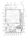
- The present invention will be described with reference to the attached drawing, which shows a side view, with parts in section and parts removed for clarity, of a home laundry drier in accordance with the teachings of the present invention.
- Number 1 in the attached drawing indicates as a whole a home laundry drier substantially comprising a preferably, though not necessarily, parallelepiped-shaped
outer box casing 2; an airtight, preferably, though not necessarily, cylindrical laundry drying tub orchamber 3 for housing the laundry to be dried, and which is fixed substantially horizontally insidecasing 2, directly facing a laundry loading and unloadingopening 2a formed in the front face ofcasing 2; a door (not shown) hinged to the front face ofcasing 2 to rotate to and from a workposition closing opening 2a in the front face to seal thelaundry drying tub 3; and a closed-circuit, hot-air generator 4 which is housed insidecasing 2 and is designed to circulate inside drying tub 3 a stream of hot air having a low moisture level, and which flows over and rapidly dries the laundry inside the tub. - Drier 1 preferably, though not necessarily, also comprises a preferably, though not necessarily,
cylindrical laundry drum 5 for housing the laundry to be dried, and which has perforated walls, or at least walls permeable to air, and is housed in axially rotating manner and preferably, though not necessarily, horizontally inside dryingtub 3; and anelectric motor 6 or similar, for rotatinglaundry drum 5 about its longitudinal axis L inside dryingtub 3. In the example shown, longitudinal axis L coincides with the longitudinal axis of dryingtub 3. -
Casing 2, dryingtub 3, the door,laundry drum 5, andelectric motor 6 are commonly known parts in the industry, and therefore not described in detail. - As for hot-
air generator 4, on the other hand, this operates in the same way as a heat-pump - which transfers heat from one fluid to another using an intermediate gaseous refrigerant subjected to a closed thermodynamic cycle, the thermodynamic principles of which are widely known and therefore not described in detail - and provides for gradually drawing air from dryingtub 3; extracting surplus moisture from the hot air drawn from dryingtub 3; heating the dehumidified air to a predetermined temperature, normally higher than the air temperature inside dryingtub 3; and feeding the heated, dehumidified air back into dryingtub 3, where it flows again over, to rapidly dry, the laundry inside the tub. - In other words, hot-
air generator 4 provides for continually dehumidifying and heating the air inside dryingtub 3 to rapidly dry the laundry inside the tub. - With reference to the accompanying drawing, hot-
air generator 4 substantially comprises: - a refrigerant compressing device 7 - commonly referred to as a compressor - which subjects the refrigerant to compression (e.g. adiabatic compression) so that refrigerant pressure and temperature are much higher at the outlet than at the inlet of
compressing device 7; - a second heat exchanger 8 - commonly referred to as an evaporator - through which the refrigerant to
compressor 7 and the airflow f from dryingtub 3 flow simultaneously, and which is designed so that the refrigerant absorbs heat from airflow f from dryingtub 3, while at the same time condensing the surplus moisture in airflow f; - a first heat exchanger 9 - commonly referred to as a condenser - through which the refrigerant from
compressor 7 and the airflow f back to dryingtub 3 flow simultaneously, and which is designed so that the refrigerant releases heat to airflow f flowing into dryingtub 3; and - a refrigerant expansion member (not shown) - for example an expansion valve or a capillary pipe - where refrigerant flowing from
condenser 9 toevaporator 8 is expanded rapidly, so that refrigerant pressure and temperature are much lower at the outlet than at the inlet of the expansion valve, thus completing the closed thermodynamic cycle in opposition tocompressor 7, which provides for rapidly compressing the refrigerant. - Hot-
air generator 4 also comprises a first connectingpipe 10 for feeding the refrigerant fromcompressor 7 tocondenser 9; a second connectingpipe 11 for feeding the refrigerant fromcondenser 9 toevaporator 8 via the refrigerant expansion member (not shown); and a third connectingpipe 12 for feeding the refrigerant fromevaporator 8 tocompressor 7. - With reference to the attached drawing, hot-
air generator 4 also comprises a number of air-circulatingconduits 13 connecting dryingtub 3 toevaporator 8,evaporator 8 to condenser 9, and condenser 9 back to dryingtub 3, so that the airflow f coming out from dryingtub 3, before flowing back into the tub, is forced to flow in rapid succession throughevaporator 8, where surplus moisture is extracted by condensation, and then throughcondenser 9, where airflow f is brought to a temperature higher than or equal to the outflow temperature from dryingtub 3; all under the control of the electric central control unit 14 of the household appliance. - Unlike known heat-pump-type, hot-air generators, hot-
air generator 4 also comprises awater tank 15 containing a predetermined amount of preferably, though not necessarily, demineralized water, aheater 16 for boiling and converting the water insidetank 15 to steam, and asteam exhaust manifold 17 for feeding the steam produced intank 15 to dryingtub 3; andheater 16 is defined by at least oneportion 16 ofpipe 10, which portion is designed to extend throughtank 15 to allow the high-temperature refrigerant (normally over 100°C) fromcompressor 7 to release heat to the water insidetank 15. - Electronic central control unit 14 of the household appliance obviously controls the active components of hot-air generator 4 - such as the
fans 18 for regulating heat exchange atevaporator 8 andcondenser 9 and/or cooling of compressor 7 - so as to regulate the temperature of the refrigerant fromcompressor 7 and so only produce steam insidetank 15 when required by the drying cycle, and possibly regulate the amount of steam as a function of the drying cycle. - Operation of drier 1 will be clear from the above description, with no further explanation required.
- The advantages of using a portion of
delivery pipe 10 ofcompressor 7 as a heater to produce steam are obvious: heat-pump-type, hot-air generator 4 can also be operated as a steam generator by simply providing anadditional tank 15 andsteam exhaust manifold 17, which are extremely cheap to produce and can be accommodated easily, even inside the alreadycrowded box casing 2. - Clearly, changes may be made to laundry drier 1 as described herein without, however, departing from the scope of the present invention.
- For example, in one variation, drier 1 also comprises a process
water recovery circuit 20, which, on command, extracts the liquid distilled water which accumulates, when the drier is running, on the bottom ofevaporator 8 as a consequence of condensation of the surplus moisture in the airflow f from dryingtub 3, and feeds the distilled water to tank 15 for use in producing steam.
Claims (4)
- A home laundry drier (1) comprising a drying tub (3) housing the laundry to be dried, and a hot-air generator (4) for circulating a stream of hot air inside the drying tub (3); the hot-air generator (4) comprising refrigerant compressing means (7) for compressing a refrigerant so that the pressure and temperature of the refrigerant at the outlet of the compressing means (7) are higher than the pressure and temperature of the refrigerant at the inlet of said compressing means (7); a first heat exchanger (9), through which the refrigerant from said compressing means (7) and the airflow (f) into said drying tub (3) flow, and which is designed so that the refrigerant releases heat to the airflow (f) into the drying tub (3); and a connecting pipe (10) for feeding the refrigerant from said compressing means (7) to said first heat exchanger (9); said laundry drier being characterized in that the hot-air generator (4) also comprises a tank (15) containing a predetermined amount of water, heating means (16) for converting the water in said tank (15) to steam, and an exhaust manifold (17) for feeding the steam produced in the tank (15) to said drying tub (3); said heating means being defined by at least one portion (16) of said first connecting pipe (10).
- A laundry drier as claimed in Claim 1, characterized in that said hot-air generator (4) also comprises a second heat exchanger (8), through which the refrigerant to said compressing means (7) and the airflow (f) from the drying tub (3) flow, and a number of air-circulating conduits (13) connecting the drying tub (3) to the second heat exchanger (8), the second heat exchanger (8) to the first heat exchanger (9), and the first heat exchanger (9) back to said drying tub (3), so that the airflow (f) coming out from the drying tub (3), before flowing back into the drying tub (3), is forced to flow in rapid succession through said second (8) and said first (9) heat exchanger; said second heat exchanger (8) being designed so that the refrigerant absorbs heat from the airflow (f) from said drying tub (3), thus condensing the surplus moisture in said airflow (f).
- A laundry drier as claimed in Claim 2, characterized in that said hot-air generator (4) also comprises a process water recovery circuit (20) which, on command, extracts the water accumulated, when the household appliance is running, on the bottom of said second heat exchanger (8), and feeds the water to said tank (15) for use in producing steam.
- A laundry drier as claimed in any one of the foregoing Claims, characterized by also comprising a laundry drum (5) for housing the laundry to be dried, and which has walls permeable to air, and is housed in axially rotating manner inside said drying tub (3); and a drive unit (6) for rotating said laundry drum (5) about its longitudinal axis (L) inside the drying tub (3).
Priority Applications (9)
| Application Number | Priority Date | Filing Date | Title |
|---|---|---|---|
| DE602007007287T DE602007007287D1 (en) | 2007-02-23 | 2007-02-23 | Clothes dryers for the household |
| EP07103016A EP1961857B1 (en) | 2007-02-23 | 2007-02-23 | Home laundry drier |
| PL07103016T PL1961857T3 (en) | 2007-02-23 | 2007-02-23 | Home laundry drier |
| AT07103016T ATE472005T1 (en) | 2007-02-23 | 2007-02-23 | DRYER FOR HOUSEHOLD |
| PCT/EP2008/001094 WO2008101623A1 (en) | 2007-02-23 | 2008-02-13 | Home laundry drier |
| MX2009008644A MX2009008644A (en) | 2007-02-23 | 2008-02-13 | Home laundry drier. |
| US12/524,125 US8082677B2 (en) | 2007-02-23 | 2008-02-13 | Home laundry drier |
| CN2008800053552A CN101617078B (en) | 2007-02-23 | 2008-02-13 | Home laundry drier |
| BRPI0807570-0A BRPI0807570A2 (en) | 2007-02-23 | 2008-02-13 | DOMESTIC CLOTHING DRYER |
Applications Claiming Priority (1)
| Application Number | Priority Date | Filing Date | Title |
|---|---|---|---|
| EP07103016A EP1961857B1 (en) | 2007-02-23 | 2007-02-23 | Home laundry drier |
Publications (2)
| Publication Number | Publication Date |
|---|---|
| EP1961857A1 EP1961857A1 (en) | 2008-08-27 |
| EP1961857B1 true EP1961857B1 (en) | 2010-06-23 |
Family
ID=38235365
Family Applications (1)
| Application Number | Title | Priority Date | Filing Date |
|---|---|---|---|
| EP07103016A Not-in-force EP1961857B1 (en) | 2007-02-23 | 2007-02-23 | Home laundry drier |
Country Status (9)
| Country | Link |
|---|---|
| US (1) | US8082677B2 (en) |
| EP (1) | EP1961857B1 (en) |
| CN (1) | CN101617078B (en) |
| AT (1) | ATE472005T1 (en) |
| BR (1) | BRPI0807570A2 (en) |
| DE (1) | DE602007007287D1 (en) |
| MX (1) | MX2009008644A (en) |
| PL (1) | PL1961857T3 (en) |
| WO (1) | WO2008101623A1 (en) |
Families Citing this family (18)
| Publication number | Priority date | Publication date | Assignee | Title |
|---|---|---|---|---|
| DE102007007354B4 (en) * | 2006-02-20 | 2013-10-10 | Lg Electronics Inc. | Clothes dryer and method of control |
| DE102006026251A1 (en) * | 2006-06-06 | 2007-12-13 | BSH Bosch und Siemens Hausgeräte GmbH | Apparatus and method for drying laundry |
| KR100830514B1 (en) * | 2006-06-12 | 2008-05-21 | 엘지전자 주식회사 | laundry dryer and method for controlling the same |
| US7997006B2 (en) * | 2007-01-12 | 2011-08-16 | Lg Electronics Inc. | Laundry machine and control method thereof |
| DE602007007287D1 (en) * | 2007-02-23 | 2010-08-05 | Electrolux Home Prod Corp | Clothes dryers for the household |
| CN102016160B (en) * | 2007-08-03 | 2013-07-17 | Lg电子株式会社 | Clothes treating apparatus |
| KR101351034B1 (en) * | 2007-08-03 | 2014-01-10 | 엘지전자 주식회사 | Laundry treating machine and controll method of the laundry treating machine |
| CN102869826B (en) * | 2010-04-28 | 2015-09-09 | Lg电子株式会社 | Device for clothing processing |
| EP2390404B1 (en) * | 2010-05-25 | 2016-07-20 | Electrolux Home Products Corporation N.V. | Laundry treatment apparatus having heat pump system |
| EP2479337B1 (en) * | 2011-01-24 | 2013-08-07 | Electrolux Home Products Corporation N.V. | Household appliance for drying objects |
| US20130255094A1 (en) * | 2012-03-27 | 2013-10-03 | Bsh Bosch Und Siemens Hausgerate Gmbh | Clothes treatment appliance with water container and a transfer pipe |
| US8769840B2 (en) * | 2012-05-14 | 2014-07-08 | King Fahd University Of Petroleum And Minerals | Recirculating dryer |
| KR101987695B1 (en) * | 2012-10-22 | 2019-06-11 | 엘지전자 주식회사 | A clothes dryer having an evaporator equipped with the second condenser |
| KR101982533B1 (en) * | 2012-11-21 | 2019-05-27 | 엘지전자 주식회사 | Dryer with heat pump |
| US9091015B2 (en) * | 2012-11-28 | 2015-07-28 | Elwha Llc | Energy efficient dryer systems |
| WO2015070897A1 (en) * | 2013-11-13 | 2015-05-21 | Electrolux Appliances Aktiebolag | Heat pump laundry dryer |
| KR101613966B1 (en) | 2014-12-29 | 2016-04-20 | 엘지전자 주식회사 | Clothes treating apparatus |
| DE102021104575A1 (en) * | 2021-02-25 | 2022-08-25 | Miele & Cie. Kg | Heat pump drying device and method for operating a heat pump drying device |
Family Cites Families (21)
| Publication number | Priority date | Publication date | Assignee | Title |
|---|---|---|---|---|
| US2114776A (en) * | 1934-05-02 | 1938-04-19 | Prosperity Co Inc | Dry cleaning machine |
| JPS6456099A (en) * | 1987-08-27 | 1989-03-02 | Mitsubishi Electric Corp | Control unit in clothing dryer |
| US5343632A (en) * | 1992-04-10 | 1994-09-06 | Advanced Dryer Systems, Inc. | Closed-loop drying process and system |
| JP3321945B2 (en) * | 1993-12-24 | 2002-09-09 | 松下電器産業株式会社 | Clothes dryer |
| DE4432489A1 (en) * | 1994-09-13 | 1996-03-14 | Schlattl Alice | Laundry dryer, drying with low air temp. without development of germs |
| CN2536633Y (en) * | 2002-02-26 | 2003-02-19 | 杨晚成 | Heating and moisture-removing device for wardrobe |
| JP2003265880A (en) * | 2002-03-19 | 2003-09-24 | Sanyo Electric Co Ltd | Washing/drying machine |
| JP4169529B2 (en) * | 2002-04-23 | 2008-10-22 | 三洋電機株式会社 | Dry cleaning device |
| JP2005095291A (en) * | 2003-09-24 | 2005-04-14 | Sanyo Electric Co Ltd | Washing/drying machine |
| JP2006122466A (en) * | 2004-10-29 | 2006-05-18 | Toshiba Corp | Laundry washer/dryer |
| KR20060061974A (en) * | 2004-12-02 | 2006-06-09 | 삼성전자주식회사 | Apparatus for remove wrinkles of clothes and method thereof |
| US7882716B2 (en) * | 2005-02-16 | 2011-02-08 | Sanyo Electric Co., Ltd. | Dry-cleaning machine |
| CN2828101Y (en) * | 2005-03-21 | 2006-10-18 | 俞宝良 | Enclosed circulation laundry drier |
| JP2007000386A (en) * | 2005-06-24 | 2007-01-11 | Matsushita Electric Ind Co Ltd | Clothes dryer |
| WO2007146050A2 (en) * | 2006-06-07 | 2007-12-21 | Waters Hot, Inc. | Bio-renewable thermal energy heating and cooling system and method |
| JP2008067742A (en) * | 2006-09-12 | 2008-03-27 | Matsushita Electric Ind Co Ltd | Clothes dryer |
| US9039407B2 (en) * | 2006-11-17 | 2015-05-26 | James K. McKnight | Powdered fuel conversion systems and methods |
| DE602007007287D1 (en) * | 2007-02-23 | 2010-08-05 | Electrolux Home Prod Corp | Clothes dryers for the household |
| KR101498027B1 (en) * | 2008-04-01 | 2015-03-03 | 엘지전자 주식회사 | Laundry treating machine and control method of the same |
| EP2163682B1 (en) * | 2008-09-12 | 2013-01-09 | Electrolux Home Products Corporation N.V. | Home laundry drier |
| KR101674942B1 (en) * | 2010-03-03 | 2016-11-10 | 엘지전자 주식회사 | Laundry Treating Apparatus |
-
2007
- 2007-02-23 DE DE602007007287T patent/DE602007007287D1/en active Active
- 2007-02-23 EP EP07103016A patent/EP1961857B1/en not_active Not-in-force
- 2007-02-23 PL PL07103016T patent/PL1961857T3/en unknown
- 2007-02-23 AT AT07103016T patent/ATE472005T1/en not_active IP Right Cessation
-
2008
- 2008-02-13 BR BRPI0807570-0A patent/BRPI0807570A2/en not_active IP Right Cessation
- 2008-02-13 WO PCT/EP2008/001094 patent/WO2008101623A1/en active Application Filing
- 2008-02-13 US US12/524,125 patent/US8082677B2/en not_active Expired - Fee Related
- 2008-02-13 MX MX2009008644A patent/MX2009008644A/en active IP Right Grant
- 2008-02-13 CN CN2008800053552A patent/CN101617078B/en not_active Expired - Fee Related
Also Published As
| Publication number | Publication date |
|---|---|
| BRPI0807570A2 (en) | 2014-07-01 |
| CN101617078B (en) | 2011-11-02 |
| US20100043245A1 (en) | 2010-02-25 |
| EP1961857A1 (en) | 2008-08-27 |
| CN101617078A (en) | 2009-12-30 |
| US8082677B2 (en) | 2011-12-27 |
| WO2008101623A1 (en) | 2008-08-28 |
| DE602007007287D1 (en) | 2010-08-05 |
| MX2009008644A (en) | 2009-08-21 |
| PL1961857T3 (en) | 2010-11-30 |
| ATE472005T1 (en) | 2010-07-15 |
Similar Documents
| Publication | Publication Date | Title |
|---|---|---|
| EP1961857B1 (en) | Home laundry drier | |
| US11578454B2 (en) | Method of controlling laundry treating apparatus | |
| EP2060671B1 (en) | Home laundry drier | |
| US8910394B2 (en) | Tumble dryer comprising a heat pump and heating system and method for operating the same | |
| EP2077350B1 (en) | Electric household appliance and relative operating method | |
| EP1970482B1 (en) | Home laundry drier | |
| CN104233735B (en) | A kind of heat pump clothes dryer and clothes-drying method | |
| KR100595763B1 (en) | Clothes dryer with a dehumidifier | |
| KR20130127816A (en) | A clothes dryer | |
| EP2163682B1 (en) | Home laundry drier | |
| CN101297075A (en) | Water supply device of dryer and control method thereof | |
| KR100826205B1 (en) | Laundry dryer | |
| JP2013081638A (en) | Clothes dryer | |
| EP2123823A1 (en) | Home laundry drier | |
| EP2147999A1 (en) | Home laundry drier | |
| KR101317621B1 (en) | Washing and drying machine | |
| KR100826204B1 (en) | Laundry dryer | |
| RU2452804C2 (en) | Household drying device for clothes | |
| EP2716807A1 (en) | A heat pump laundry drying machine and a method for operating a heat pump laundry drying machine | |
| KR101174656B1 (en) | Clothes dryer with vapor compression cycle system | |
| KR100434371B1 (en) | Dryer and drying method | |
| KR100595762B1 (en) | Clothes dryer with vapor compression cycle system |
Legal Events
| Date | Code | Title | Description |
|---|---|---|---|
| PUAI | Public reference made under article 153(3) epc to a published international application that has entered the european phase |
Free format text: ORIGINAL CODE: 0009012 |
|
| AK | Designated contracting states |
Kind code of ref document: A1 Designated state(s): AT BE BG CH CY CZ DE DK EE ES FI FR GB GR HU IE IS IT LI LT LU LV MC NL PL PT RO SE SI SK TR |
|
| AX | Request for extension of the european patent |
Extension state: AL BA HR MK RS |
|
| 17P | Request for examination filed |
Effective date: 20090126 |
|
| AKX | Designation fees paid |
Designated state(s): AT BE BG CH CY CZ DE DK EE ES FI FR GB GR HU IE IS IT LI LT LU LV MC NL PL PT RO SE SI SK TR |
|
| GRAP | Despatch of communication of intention to grant a patent |
Free format text: ORIGINAL CODE: EPIDOSNIGR1 |
|
| GRAS | Grant fee paid |
Free format text: ORIGINAL CODE: EPIDOSNIGR3 |
|
| GRAA | (expected) grant |
Free format text: ORIGINAL CODE: 0009210 |
|
| AK | Designated contracting states |
Kind code of ref document: B1 Designated state(s): AT BE BG CH CY CZ DE DK EE ES FI FR GB GR HU IE IS IT LI LT LU LV MC NL PL PT RO SE SI SK TR |
|
| REG | Reference to a national code |
Ref country code: CH Ref legal event code: EP |
|
| REG | Reference to a national code |
Ref country code: IE Ref legal event code: FG4D |
|
| REF | Corresponds to: |
Ref document number: 602007007287 Country of ref document: DE Date of ref document: 20100805 Kind code of ref document: P |
|
| REG | Reference to a national code |
Ref country code: NL Ref legal event code: VDEP Effective date: 20100623 |
|
| PG25 | Lapsed in a contracting state [announced via postgrant information from national office to epo] |
Ref country code: LT Free format text: LAPSE BECAUSE OF FAILURE TO SUBMIT A TRANSLATION OF THE DESCRIPTION OR TO PAY THE FEE WITHIN THE PRESCRIBED TIME-LIMIT Effective date: 20100623 Ref country code: SE Free format text: LAPSE BECAUSE OF FAILURE TO SUBMIT A TRANSLATION OF THE DESCRIPTION OR TO PAY THE FEE WITHIN THE PRESCRIBED TIME-LIMIT Effective date: 20100623 |
|
| LTIE | Lt: invalidation of european patent or patent extension |
Effective date: 20100623 |
|
| PG25 | Lapsed in a contracting state [announced via postgrant information from national office to epo] |
Ref country code: SI Free format text: LAPSE BECAUSE OF FAILURE TO SUBMIT A TRANSLATION OF THE DESCRIPTION OR TO PAY THE FEE WITHIN THE PRESCRIBED TIME-LIMIT Effective date: 20100623 Ref country code: LV Free format text: LAPSE BECAUSE OF FAILURE TO SUBMIT A TRANSLATION OF THE DESCRIPTION OR TO PAY THE FEE WITHIN THE PRESCRIBED TIME-LIMIT Effective date: 20100623 Ref country code: FI Free format text: LAPSE BECAUSE OF FAILURE TO SUBMIT A TRANSLATION OF THE DESCRIPTION OR TO PAY THE FEE WITHIN THE PRESCRIBED TIME-LIMIT Effective date: 20100623 Ref country code: AT Free format text: LAPSE BECAUSE OF FAILURE TO SUBMIT A TRANSLATION OF THE DESCRIPTION OR TO PAY THE FEE WITHIN THE PRESCRIBED TIME-LIMIT Effective date: 20100623 |
|
| REG | Reference to a national code |
Ref country code: PL Ref legal event code: T3 |
|
| PG25 | Lapsed in a contracting state [announced via postgrant information from national office to epo] |
Ref country code: EE Free format text: LAPSE BECAUSE OF FAILURE TO SUBMIT A TRANSLATION OF THE DESCRIPTION OR TO PAY THE FEE WITHIN THE PRESCRIBED TIME-LIMIT Effective date: 20100623 Ref country code: NL Free format text: LAPSE BECAUSE OF FAILURE TO SUBMIT A TRANSLATION OF THE DESCRIPTION OR TO PAY THE FEE WITHIN THE PRESCRIBED TIME-LIMIT Effective date: 20100623 Ref country code: GR Free format text: LAPSE BECAUSE OF FAILURE TO SUBMIT A TRANSLATION OF THE DESCRIPTION OR TO PAY THE FEE WITHIN THE PRESCRIBED TIME-LIMIT Effective date: 20100924 |
|
| PG25 | Lapsed in a contracting state [announced via postgrant information from national office to epo] |
Ref country code: RO Free format text: LAPSE BECAUSE OF FAILURE TO SUBMIT A TRANSLATION OF THE DESCRIPTION OR TO PAY THE FEE WITHIN THE PRESCRIBED TIME-LIMIT Effective date: 20100623 Ref country code: SK Free format text: LAPSE BECAUSE OF FAILURE TO SUBMIT A TRANSLATION OF THE DESCRIPTION OR TO PAY THE FEE WITHIN THE PRESCRIBED TIME-LIMIT Effective date: 20100623 Ref country code: BE Free format text: LAPSE BECAUSE OF FAILURE TO SUBMIT A TRANSLATION OF THE DESCRIPTION OR TO PAY THE FEE WITHIN THE PRESCRIBED TIME-LIMIT Effective date: 20100623 Ref country code: CY Free format text: LAPSE BECAUSE OF FAILURE TO SUBMIT A TRANSLATION OF THE DESCRIPTION OR TO PAY THE FEE WITHIN THE PRESCRIBED TIME-LIMIT Effective date: 20100623 Ref country code: CZ Free format text: LAPSE BECAUSE OF FAILURE TO SUBMIT A TRANSLATION OF THE DESCRIPTION OR TO PAY THE FEE WITHIN THE PRESCRIBED TIME-LIMIT Effective date: 20100623 Ref country code: IS Free format text: LAPSE BECAUSE OF FAILURE TO SUBMIT A TRANSLATION OF THE DESCRIPTION OR TO PAY THE FEE WITHIN THE PRESCRIBED TIME-LIMIT Effective date: 20101023 Ref country code: PT Free format text: LAPSE BECAUSE OF FAILURE TO SUBMIT A TRANSLATION OF THE DESCRIPTION OR TO PAY THE FEE WITHIN THE PRESCRIBED TIME-LIMIT Effective date: 20101025 |
|
| RAP2 | Party data changed (patent owner data changed or rights of a patent transferred) |
Owner name: ELECTROLUX HOME PRODUCTS CORPORATION N.V. |
|
| PG25 | Lapsed in a contracting state [announced via postgrant information from national office to epo] |
Ref country code: DK Free format text: LAPSE BECAUSE OF FAILURE TO SUBMIT A TRANSLATION OF THE DESCRIPTION OR TO PAY THE FEE WITHIN THE PRESCRIBED TIME-LIMIT Effective date: 20100623 |
|
| PLBE | No opposition filed within time limit |
Free format text: ORIGINAL CODE: 0009261 |
|
| STAA | Information on the status of an ep patent application or granted ep patent |
Free format text: STATUS: NO OPPOSITION FILED WITHIN TIME LIMIT |
|
| 26N | No opposition filed |
Effective date: 20110324 |
|
| REG | Reference to a national code |
Ref country code: DE Ref legal event code: R097 Ref document number: 602007007287 Country of ref document: DE Effective date: 20110323 |
|
| PG25 | Lapsed in a contracting state [announced via postgrant information from national office to epo] |
Ref country code: MC Free format text: LAPSE BECAUSE OF NON-PAYMENT OF DUE FEES Effective date: 20110228 |
|
| REG | Reference to a national code |
Ref country code: CH Ref legal event code: PL |
|
| PG25 | Lapsed in a contracting state [announced via postgrant information from national office to epo] |
Ref country code: LI Free format text: LAPSE BECAUSE OF NON-PAYMENT OF DUE FEES Effective date: 20110228 Ref country code: CH Free format text: LAPSE BECAUSE OF NON-PAYMENT OF DUE FEES Effective date: 20110228 |
|
| REG | Reference to a national code |
Ref country code: IE Ref legal event code: MM4A |
|
| PG25 | Lapsed in a contracting state [announced via postgrant information from national office to epo] |
Ref country code: IE Free format text: LAPSE BECAUSE OF NON-PAYMENT OF DUE FEES Effective date: 20110223 |
|
| REG | Reference to a national code |
Ref country code: FR Ref legal event code: CA Effective date: 20120116 |
|
| PGFP | Annual fee paid to national office [announced via postgrant information from national office to epo] |
Ref country code: IT Payment date: 20120222 Year of fee payment: 6 |
|
| PGFP | Annual fee paid to national office [announced via postgrant information from national office to epo] |
Ref country code: GB Payment date: 20130218 Year of fee payment: 7 Ref country code: DE Payment date: 20130219 Year of fee payment: 7 Ref country code: FR Payment date: 20130301 Year of fee payment: 7 |
|
| PG25 | Lapsed in a contracting state [announced via postgrant information from national office to epo] |
Ref country code: LU Free format text: LAPSE BECAUSE OF NON-PAYMENT OF DUE FEES Effective date: 20110223 |
|
| PGFP | Annual fee paid to national office [announced via postgrant information from national office to epo] |
Ref country code: PL Payment date: 20130124 Year of fee payment: 7 |
|
| PG25 | Lapsed in a contracting state [announced via postgrant information from national office to epo] |
Ref country code: BG Free format text: LAPSE BECAUSE OF FAILURE TO SUBMIT A TRANSLATION OF THE DESCRIPTION OR TO PAY THE FEE WITHIN THE PRESCRIBED TIME-LIMIT Effective date: 20100923 Ref country code: TR Free format text: LAPSE BECAUSE OF FAILURE TO SUBMIT A TRANSLATION OF THE DESCRIPTION OR TO PAY THE FEE WITHIN THE PRESCRIBED TIME-LIMIT Effective date: 20100623 |
|
| PG25 | Lapsed in a contracting state [announced via postgrant information from national office to epo] |
Ref country code: HU Free format text: LAPSE BECAUSE OF FAILURE TO SUBMIT A TRANSLATION OF THE DESCRIPTION OR TO PAY THE FEE WITHIN THE PRESCRIBED TIME-LIMIT Effective date: 20100623 Ref country code: ES Free format text: LAPSE BECAUSE OF FAILURE TO SUBMIT A TRANSLATION OF THE DESCRIPTION OR TO PAY THE FEE WITHIN THE PRESCRIBED TIME-LIMIT Effective date: 20101004 |
|
| REG | Reference to a national code |
Ref country code: DE Ref legal event code: R119 Ref document number: 602007007287 Country of ref document: DE |
|
| GBPC | Gb: european patent ceased through non-payment of renewal fee |
Effective date: 20140223 |
|
| REG | Reference to a national code |
Ref country code: FR Ref legal event code: ST Effective date: 20141031 |
|
| REG | Reference to a national code |
Ref country code: DE Ref legal event code: R119 Ref document number: 602007007287 Country of ref document: DE Effective date: 20140902 |
|
| PG25 | Lapsed in a contracting state [announced via postgrant information from national office to epo] |
Ref country code: FR Free format text: LAPSE BECAUSE OF NON-PAYMENT OF DUE FEES Effective date: 20140228 Ref country code: DE Free format text: LAPSE BECAUSE OF NON-PAYMENT OF DUE FEES Effective date: 20140902 Ref country code: GB Free format text: LAPSE BECAUSE OF NON-PAYMENT OF DUE FEES Effective date: 20140223 |
|
| PG25 | Lapsed in a contracting state [announced via postgrant information from national office to epo] |
Ref country code: PL Free format text: LAPSE BECAUSE OF NON-PAYMENT OF DUE FEES Effective date: 20140223 |
|
| REG | Reference to a national code |
Ref country code: PL Ref legal event code: LAPE |
|
| PG25 | Lapsed in a contracting state [announced via postgrant information from national office to epo] |
Ref country code: IT Free format text: LAPSE BECAUSE OF NON-PAYMENT OF DUE FEES Effective date: 20140223 |