EP1961600A1 - Ea material, its fixing clip and fixing structure - Google Patents
Ea material, its fixing clip and fixing structure Download PDFInfo
- Publication number
- EP1961600A1 EP1961600A1 EP06833492A EP06833492A EP1961600A1 EP 1961600 A1 EP1961600 A1 EP 1961600A1 EP 06833492 A EP06833492 A EP 06833492A EP 06833492 A EP06833492 A EP 06833492A EP 1961600 A1 EP1961600 A1 EP 1961600A1
- Authority
- EP
- European Patent Office
- Prior art keywords
- clip
- flange
- projecting
- locking piece
- securing
- Prior art date
- Legal status (The legal status is an assumption and is not a legal conclusion. Google has not performed a legal analysis and makes no representation as to the accuracy of the status listed.)
- Granted
Links
Images




Classifications
-
- F—MECHANICAL ENGINEERING; LIGHTING; HEATING; WEAPONS; BLASTING
- F16—ENGINEERING ELEMENTS AND UNITS; GENERAL MEASURES FOR PRODUCING AND MAINTAINING EFFECTIVE FUNCTIONING OF MACHINES OR INSTALLATIONS; THERMAL INSULATION IN GENERAL
- F16B—DEVICES FOR FASTENING OR SECURING CONSTRUCTIONAL ELEMENTS OR MACHINE PARTS TOGETHER, e.g. NAILS, BOLTS, CIRCLIPS, CLAMPS, CLIPS OR WEDGES; JOINTS OR JOINTING
- F16B21/00—Means for preventing relative axial movement of a pin, spigot, shaft or the like and a member surrounding it; Stud-and-socket releasable fastenings
- F16B21/06—Releasable fastening devices with snap-action
- F16B21/08—Releasable fastening devices with snap-action in which the stud, pin, or spigot has a resilient part
- F16B21/086—Releasable fastening devices with snap-action in which the stud, pin, or spigot has a resilient part the shank of the stud, pin or spigot having elevations, ribs, fins or prongs intended for deformation or tilting predominantly in a direction perpendicular to the direction of insertion
-
- B—PERFORMING OPERATIONS; TRANSPORTING
- B60—VEHICLES IN GENERAL
- B60J—WINDOWS, WINDSCREENS, NON-FIXED ROOFS, DOORS, OR SIMILAR DEVICES FOR VEHICLES; REMOVABLE EXTERNAL PROTECTIVE COVERINGS SPECIALLY ADAPTED FOR VEHICLES
- B60J5/00—Doors
- B60J5/04—Doors arranged at the vehicle sides
- B60J5/0468—Fixation or mounting means specific for door components
-
- B—PERFORMING OPERATIONS; TRANSPORTING
- B60—VEHICLES IN GENERAL
- B60R—VEHICLES, VEHICLE FITTINGS, OR VEHICLE PARTS, NOT OTHERWISE PROVIDED FOR
- B60R13/00—Elements for body-finishing, identifying, or decorating; Arrangements or adaptations for advertising purposes
- B60R13/02—Internal Trim mouldings ; Internal Ledges; Wall liners for passenger compartments; Roof liners
- B60R13/0206—Arrangements of fasteners and clips specially adapted for attaching inner vehicle liners or mouldings
-
- F—MECHANICAL ENGINEERING; LIGHTING; HEATING; WEAPONS; BLASTING
- F16—ENGINEERING ELEMENTS AND UNITS; GENERAL MEASURES FOR PRODUCING AND MAINTAINING EFFECTIVE FUNCTIONING OF MACHINES OR INSTALLATIONS; THERMAL INSULATION IN GENERAL
- F16B—DEVICES FOR FASTENING OR SECURING CONSTRUCTIONAL ELEMENTS OR MACHINE PARTS TOGETHER, e.g. NAILS, BOLTS, CIRCLIPS, CLAMPS, CLIPS OR WEDGES; JOINTS OR JOINTING
- F16B5/00—Joining sheets or plates, e.g. panels, to one another or to strips or bars parallel to them
- F16B5/06—Joining sheets or plates, e.g. panels, to one another or to strips or bars parallel to them by means of clamps or clips
- F16B5/0607—Joining sheets or plates, e.g. panels, to one another or to strips or bars parallel to them by means of clamps or clips joining sheets or plates to each other
- F16B5/0621—Joining sheets or plates, e.g. panels, to one another or to strips or bars parallel to them by means of clamps or clips joining sheets or plates to each other in parallel relationship
- F16B5/0642—Joining sheets or plates, e.g. panels, to one another or to strips or bars parallel to them by means of clamps or clips joining sheets or plates to each other in parallel relationship the plates being arranged one on top of the other and in full close contact with each other
-
- F—MECHANICAL ENGINEERING; LIGHTING; HEATING; WEAPONS; BLASTING
- F16—ENGINEERING ELEMENTS AND UNITS; GENERAL MEASURES FOR PRODUCING AND MAINTAINING EFFECTIVE FUNCTIONING OF MACHINES OR INSTALLATIONS; THERMAL INSULATION IN GENERAL
- F16B—DEVICES FOR FASTENING OR SECURING CONSTRUCTIONAL ELEMENTS OR MACHINE PARTS TOGETHER, e.g. NAILS, BOLTS, CIRCLIPS, CLAMPS, CLIPS OR WEDGES; JOINTS OR JOINTING
- F16B5/00—Joining sheets or plates, e.g. panels, to one another or to strips or bars parallel to them
- F16B5/06—Joining sheets or plates, e.g. panels, to one another or to strips or bars parallel to them by means of clamps or clips
- F16B5/0607—Joining sheets or plates, e.g. panels, to one another or to strips or bars parallel to them by means of clamps or clips joining sheets or plates to each other
- F16B5/0621—Joining sheets or plates, e.g. panels, to one another or to strips or bars parallel to them by means of clamps or clips joining sheets or plates to each other in parallel relationship
- F16B5/0657—Joining sheets or plates, e.g. panels, to one another or to strips or bars parallel to them by means of clamps or clips joining sheets or plates to each other in parallel relationship at least one of the plates providing a raised structure, e.g. of the doghouse type, for connection with the clamps or clips of the other plate
-
- B—PERFORMING OPERATIONS; TRANSPORTING
- B60—VEHICLES IN GENERAL
- B60R—VEHICLES, VEHICLE FITTINGS, OR VEHICLE PARTS, NOT OTHERWISE PROVIDED FOR
- B60R13/00—Elements for body-finishing, identifying, or decorating; Arrangements or adaptations for advertising purposes
- B60R13/08—Insulating elements, e.g. for sound insulation
-
- B—PERFORMING OPERATIONS; TRANSPORTING
- B60—VEHICLES IN GENERAL
- B60R—VEHICLES, VEHICLE FITTINGS, OR VEHICLE PARTS, NOT OTHERWISE PROVIDED FOR
- B60R21/00—Arrangements or fittings on vehicles for protecting or preventing injuries to occupants or pedestrians in case of accidents or other traffic risks
- B60R21/02—Occupant safety arrangements or fittings, e.g. crash pads
- B60R21/04—Padded linings for the vehicle interior ; Energy absorbing structures associated with padded or non-padded linings
-
- Y—GENERAL TAGGING OF NEW TECHNOLOGICAL DEVELOPMENTS; GENERAL TAGGING OF CROSS-SECTIONAL TECHNOLOGIES SPANNING OVER SEVERAL SECTIONS OF THE IPC; TECHNICAL SUBJECTS COVERED BY FORMER USPC CROSS-REFERENCE ART COLLECTIONS [XRACs] AND DIGESTS
- Y10—TECHNICAL SUBJECTS COVERED BY FORMER USPC
- Y10T—TECHNICAL SUBJECTS COVERED BY FORMER US CLASSIFICATION
- Y10T24/00—Buckles, buttons, clasps, etc.
- Y10T24/30—Trim molding fastener
- Y10T24/309—Plastic type
-
- Y—GENERAL TAGGING OF NEW TECHNOLOGICAL DEVELOPMENTS; GENERAL TAGGING OF CROSS-SECTIONAL TECHNOLOGIES SPANNING OVER SEVERAL SECTIONS OF THE IPC; TECHNICAL SUBJECTS COVERED BY FORMER USPC CROSS-REFERENCE ART COLLECTIONS [XRACs] AND DIGESTS
- Y10—TECHNICAL SUBJECTS COVERED BY FORMER USPC
- Y10T—TECHNICAL SUBJECTS COVERED BY FORMER US CLASSIFICATION
- Y10T24/00—Buckles, buttons, clasps, etc.
- Y10T24/42—Independent, headed, aperture pass-through fastener
-
- Y—GENERAL TAGGING OF NEW TECHNOLOGICAL DEVELOPMENTS; GENERAL TAGGING OF CROSS-SECTIONAL TECHNOLOGIES SPANNING OVER SEVERAL SECTIONS OF THE IPC; TECHNICAL SUBJECTS COVERED BY FORMER USPC CROSS-REFERENCE ART COLLECTIONS [XRACs] AND DIGESTS
- Y10—TECHNICAL SUBJECTS COVERED BY FORMER USPC
- Y10T—TECHNICAL SUBJECTS COVERED BY FORMER US CLASSIFICATION
- Y10T24/00—Buckles, buttons, clasps, etc.
- Y10T24/44—Clasp, clip, support-clamp, or required component thereof
- Y10T24/44017—Clasp, clip, support-clamp, or required component thereof with specific mounting means for attaching to rigid or semirigid supporting structure or structure-to-be-secured
-
- Y—GENERAL TAGGING OF NEW TECHNOLOGICAL DEVELOPMENTS; GENERAL TAGGING OF CROSS-SECTIONAL TECHNOLOGIES SPANNING OVER SEVERAL SECTIONS OF THE IPC; TECHNICAL SUBJECTS COVERED BY FORMER USPC CROSS-REFERENCE ART COLLECTIONS [XRACs] AND DIGESTS
- Y10—TECHNICAL SUBJECTS COVERED BY FORMER USPC
- Y10T—TECHNICAL SUBJECTS COVERED BY FORMER US CLASSIFICATION
- Y10T24/00—Buckles, buttons, clasps, etc.
- Y10T24/44—Clasp, clip, support-clamp, or required component thereof
- Y10T24/44017—Clasp, clip, support-clamp, or required component thereof with specific mounting means for attaching to rigid or semirigid supporting structure or structure-to-be-secured
- Y10T24/44026—Clasp, clip, support-clamp, or required component thereof with specific mounting means for attaching to rigid or semirigid supporting structure or structure-to-be-secured for cooperating with aperture in supporting structure or structure-to-be-secured
Definitions
- the present invention relates to EA members (energy absorption members) and to clips and structures for securing the same, and in particular to EA members suitable for application to sheet metal panels of automobile bodies and to clips and structures for securing the same.
- Sheet metal panels serving as automobile door bodies are provided with EA members made of rigid urethane foam for the purpose of energy absorption (EA) in the likelihood of side-on collision.
- EA energy absorption
- a structure shown in Figs. 12a to 13b has been disclosed in Japanese Unexamined Patent Application Publication No. 2004-132462 .
- Fig. 12a is a substantially horizontal cross-sectional view showing an EA-member securing structure disclosed in the aforementioned document.
- Fig. 12b is a side view of a locking member included in the EA-member securing structure.
- Fig. 13a is a cross-sectional view for describing a method for manufacturing an EA member provided with the locking member.
- Fig. 13b is an enlarged view of a part shown in Fig. 13a .
- a plate-like EA member 1 made of synthetic resin such as rigid urethane foam is secured with a clip 3 to a component serving as a body sheet metal panel (a door trim in this case) 2.
- a hole 4 is provided in the body sheet metal panel 2. The clip 3 is caught in the hole 4.
- the clip 3 has a cylindrical body 6, an anchor 5 projecting outward like a collar from the bottom of the cylindrical body 6, a flange 7 projecting outward like a collar from the top of the cylindrical body 6, and a plurality (two in this embodiment) of projections 8 and 8 projecting in a direction parallel to the cylinder axis of the cylindrical body 6 from the top end face of the cylindrical body 6.
- the projections 8 and 8 are provided opposite each other in the diametrical direction of the hole 4.
- a catch 8a projects laterally with a space 9 being provided between the catch 8a and the flange 7.
- the amount of the lateral projection of the catch 8a gradually becomes larger toward the flange 7. That is, the outer sides of the projections 8 and 8 are tapered. This enables easy insertion of the projections 8 and 8 into the hole 4.
- the clip 3 is made of synthetic resin and is generally molded as an integral body.
- the projections 8 and 8 are resiliently deformable toward each other.
- the clip 3 in the synthetic resin forming the clip 3, ferromagnetic particles such as ferrite particles are dispersed. Further, the clip 3 is in the magnetized state because of magnetization performed on the ferromagnetic particles. Thus, the clip 3 can be magnetically attracted to and held by a mold used for molding the EA member 1.
- the cylindrical body 6 and the anchor 5 of the clip 3 are embedded in the EA member 1.
- the bottom surface of the flange 7 is flush with the surface of the EA member 1.
- the top surface of the flange 7 may be flush with the surface of the EA member 1. It is also allowable that the lower half of the flange 7 is embedded in the EA member 1 while the upper half of the flange 7 projects from the surface of the EA member 1.
- the flange 7 projects from the surface of the EA member 1 as in the case shown in Fig. 12 , for example, the positional relationship between the EA member 1 and the body sheet metal panel 2 in a direction toward and away from each other would be uniquely defined by pinching the body sheet metal panel 2 between the flange 7 and the catches 8a.
- the EA member 1 By putting the EA member 1 provided with the clip 3 on the body sheet metal panel 2 while inserting the projections 8 and 8 into the hole 4, the EA member 1 is secured to the body sheet metal panel 2.
- the projections 8 and 8 are pushed into the hole 4. Since the catches 8a are pressed against the inner periphery of the hole 4, the projections 8 and 8 are bent toward each other and thus are inserted into the hole 4.
- the projections 8 and 8 resiliently restore their original shapes and the sides of the projections 8 are resiliently pressed against the inner periphery of the hole 4, whereby the periphery of the hole 4 being fitted in the space 9 is pinched between the flange 7 and the catches 8a. In this manner, the EA member 1 is secured to the body sheet metal panel 2.
- a mold constituted by a lower mold 10 and an upper mold 11 is used as shown in Figs. 13a and 13b . While the clip 3 is made to be held in a surface of the upper mold 11 facing a cavity, a synthetic resin material is supplied into the cavity and is molded. In the case of using urethane or the like, a formulated concentrate of urethane or the like is supplied into the lower mold 10 and is caused to foam.
- the upper mold 11 that holds the clip 3 has a recess 12 that receives the projections 8 and 8 of the clip 3.
- a ring member 13 made of a ferromagnetic material for example, an alloy such as an iron-cobalt alloy or a ceramic material such as ferrite
- magnetizing one of the ring member 13 and the clip 3 the clip 3 can be magnetically attracted to and held by the ring member 13.
- Patent Document 1 Japanese Unexamined Patent Application Publication No. 2004-132462
- the clip 3 shown in Figs. 12a to 13b can only be applied to the body sheet metal panel 2 whose thickness matches the space between the flange 7 and the catches 8a.
- the catches 8a cannot completely pass through the hole 4 and therefore the EA member 1 cannot be locked to the body sheet metal panel 2.
- the body sheet metal panel 2 is thinner than that shown in Figs. 12a and 12b , the EA member 1 wobbles.
- the present invention aims to solve such problems in the conventional art and to provide a clip capable of firmly securing an EA member even if the thickness of a component such as a vehicle-body sheet metal panel is changed, an EA member provided with such a clip, and a structure for securing such an EA member.
- a first aspect provides a clip for securing an attachment to a securing plate.
- the clip includes a head to be embedded in the attachment, a flange to be exposed above the securing plate, and a leg extending downward from the flange.
- the leg includes a substantially cylindrical main leg and a resilient locking piece.
- the main leg has at a tip thereof a plurality of projecting portions.
- the resilient locking piece extends in a direction of a length of the main leg, is connected at an upper portion thereof to the main leg, and has at a bottom thereof a free end.
- the resilient locking piece further includes in an upper portion thereof a sloping surface diverging downward, in a lower portion thereof a sloping surface diverging upward, and a steep sloping portion near a point where the sloping surfaces meet.
- a second aspect provides a clip for securing an EA member to a component.
- the clip includes a flange to be positioned at a surface of the EA member, a shaft projecting from the flange toward an EA-member side, an anchor spreading from an end of the shaft and to be embedded in the EA member, and a locking section projecting from the flange on a side opposite the shaft and configured to lock the clip in the component.
- the locking section includes an upright segment standing upright from the flange, and a locking piece laterally projecting from a side surface of the upright segment and resiliently thrustable and retractable in a projecting direction of the locking piece. The locking piece extends parallel to a direction in which the upright segment stands upright.
- the locking piece forms in a portion halfway in an extending direction thereof a most projecting point projecting farthest in the lateral direction, in a portion thereof near a tip of the upright segment with respect to the most projecting point a first slope whose amount of projection gradually becomes smaller toward the tip, and in a portion thereof near the flange with respect to the most projecting point a second slope whose amount of projection gradually becomes smaller toward the flange.
- the upright segment may be cylindrical and have in the side surface thereof an opening, and the locking piece may be resiliently connected to a portion of a periphery of the opening, the portion being farthest from the flange.
- the upright segment may have along a periphery thereof the locking piece in a plurality with intervals therebetween.
- the anchor may have a cut therein, the cut having a shape made by cutting off an outer peripheral portion of the anchor.
- a third aspect provides an EA member integrally provided with the clip according to the first or second aspect.
- the flange of the clip is positioned at a surface of the EA member, the locking section projects from the EA member, and the anchor is embedded in the EA member.
- a fourth aspect provides an EA-member securing structure in which the EA member according to the third aspect is secured to a component.
- the EA member is secured to the component while the locking piece of the clip is caught by a lock catching part provided to the component.
- the lock catching part may be a hole.
- the second slope of the clip may be locked at an edge of the hole remote from the EA member.
- the component may be a vehicle-body sheet metal panel.
- the EA member may be made of synthetic resin such as rigid urethane.
- the securing clip according to the first aspect used for securing a buffer or an energy absorber made of a foam material or the like to a securing plate has at its end a plurality of projecting portions for locating a hole. In inserting the securing clip into a through hole bored in the securing plate, the hole can be located easily even at a securing site having bad accessibility.
- the resilient locking piece of the clip according to the first aspect has a sloping surface diverging from a lower position toward a central position thereof, and a peak point at the outermost position in the sloping surface.
- the locking piece also has a steep sloping portion of a short length immediately above the peak forming the largest diameter, and, as an extension of the steep sloping portion, another sloping surface converging toward the flange.
- the clip according to the second aspect has the most projecting point halfway in the locking piece.
- the second slope is provided near the flange with respect to the most projecting point.
- the clip can be applied to a component, such as a vehicle-body sheet metal panel, having a thickness that allows the second slope to be in contact with an edge (an edge opposite an edge on the EA-member side) of a hole provided in the component.
- the first slope provided near the tip with respect to the foregoing slope is brought into contact with the inner periphery of the hole while the locking section of the clip is being inserted into the hole in the component. During the insertion, the locking piece gradually retracts. After the most projecting point of the clip has passed through the hole, the second slope is locked at the edge of the hole.
- Fig. 1 is a perspective view of a clip according to the embodiment.
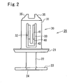
- Fig. 2 is a front view of the clip shown in Fig. 1 .
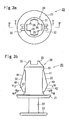
- Fig. 3a is a plan view of the clip shown in Fig. 1 .
- Fig. 3b is a side view of the clip shown in Fig. 1 .
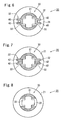
- Fig. 4 is a cross-sectional view of Fig. 3a taken along the line IV-IV.
- Fig. 5 is a cross-sectional view of Fig. 3a taken along the line V-V.
- Fig. 6 is a cross-sectional view of Fig. 3b taken along the line VI-VI.
- Fig. 7 is a cross-sectional view of Fig. 3b taken along the line VII-VII.
- Fig. 1 is a perspective view of a clip according to the embodiment.
- Fig. 2 is a front view of the clip shown in Fig. 1 .
- Fig. 3a is a plan view of
- Fig. 8 is a cross-sectional view of Fig. 3b taken along the line VIII-VIII.
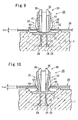
- Fig. 9 is a cross-sectional view showing an EA-member securing structure in the case of a vehicle-body sheet metal panel having a small thickness.
- Fig. 10 is a cross-sectional view showing the EA-member securing structure in the case of a vehicle-body sheet metal panel having a large thickness.
- Fig. 11 is a cross-sectional view showing a state where the clip is fitted in a mold.
- a clip 20 is made of synthetic resin and is molded as an integral body.
- the clip 20 has a flange 21 to be positioned at the surface of an EA member, a shaft 22 projecting from the flange 21 toward an EA-member side, an anchor 23 spreading from an end of the shaft 22 and to be embedded in the EA member, cuts 24 provided in the anchor 23, and a locking section 30 projecting from the flange 21 on a side opposite the shaft 22.
- the locking section 30 has a cylindrical upright segment 31 standing upright from the flange 21, and locking pieces 32 projecting laterally from the side surface of the upright segment 31 and resiliently thrustable and retractable in their projecting direction.
- the locking pieces 32 extend parallel to a direction in which the upright segment 31 stands upright.
- Each locking piece 32 has a most projecting point 40 projecting farthest in the lateral direction, halfway in a direction in which the locking piece 32 extends.
- a portion of the locking piece 32 near the tip of the upright segment 31 with respect to the most projecting point 40 forms a first slope 41 whose amount of projection gradually becomes smaller toward the tip.
- a portion of the locking piece 32 near the flange 21 with respect to the most projecting point 40 forms a second slope 42 whose amount of projection gradually becomes smaller toward the flange 21.
- the angle at which the first slope 41 and the cylinder axis of the upright segment 31 cross each other is preferably about 15 to 25 degrees.
- the angle at which the second slope 42 and the cylinder axis of the upright segment 31 cross each other is preferably about 20 to 30 degrees.
- the bottom of the locking piece 32 i.e., the surface nearest to the flange 21 in the drawing, forms a bottom end face 32e parallel to the flange 21.
- the distance (interval) between the bottom end face 32e and the flange 21 is preferably about 1 to 5 mm.
- the side surface of the cylindrical upright segment 31 has two openings 33 extending parallel to the cylinder axis.
- Each locking piece 32 is resiliently connected to a portion of the periphery of the corresponding one of the openings 33 and 33, the portion being farthest from the flange 21.
- two openings 33 and two locking pieces 32 are provided in and to the upright segment 32 in such a manner as to be respectively positioned opposite each other diametrically.
- three or more openings 33 and three or more locking pieces 32 may be provided in and to the upright segment 31 along the peripheral surface of the upright segment 31 with intervals therebetween. It is practical to set the number of locking pieces 32 to about 2 to 4.
- the top of the upright segment 31 is tapered off.
- the cylindrical upright segment 31 has a cylindrical peripheral surface but a cruciform hollow inside. This forms four projections 35 at the top of the upright segment 31.
- the shaft 22 and the anchor 23 of the clip 20 are embedded in an EA member 1 in such a manner that the flange 21 is positioned at the surface of the EA member 1 and that the locking section 30 projects from the EA member 1.
- the EA member 1 is put on the body sheet metal panel 2A or 2B while the clip 20 is introduced into a hole 4 provided in the body sheet metal panel 2A or 2B.
- the locking pieces 32 of the clip 20 are pressed against the inner periphery of the hole 4.
- the locking pieces 32 gradually retract into their respective openings 33 while approaching each other diametrically.
- the second slopes 42 are pressed against an edge of the hole 4 remote from the EA member 1. This causes the body sheet metal panel 2A or 2B to be pinched between the flange 21 and the second slopes 42, whereby the EA member 1 is fitted to and held by the body sheet metal panel 2A or 2B.
- the EA member 1 can be firmly held by the body sheet metal panel 2A or 2B as long as the edge of the hole 4 remote from the EA member 1 is brought into contact with the second slopes 42.
- the EA member 1 provided with the clip 20 is manufactured by performing molding with the clip 20 being held in an inner surface of an EA-member mold 50 as shown in Fig. 11 .
- This mold has a clip holding hole 51 provided therein so as to face a cavity.
- the mouth of the hole 51 forms a small-diameter portion 51a.
- the clip 20 is fitted by pushing the locking section 30 into the hole 51. In this step, a tactile click sensation is provided when the most projecting points 40 pass through the small-diameter portion 51a. This enables a molding worker to recognize that the clip 20 has been pushed into the hole 51 sufficiently when fitting the clip 20 into the hole 51.
- the anchor 23 of the clip 20 has the cuts 24. Therefore, when molding of the EA member is performed as shown in Fig. 11 , a sufficient amount of resin such as urethane is supplied between the flange 21 and the anchor 23, whereby the clip 20 can be firmly integrated with the EA member.
- first slopes 41 are formed allowing for the thickness of the securing plate.
- the bottom surface of the flange 21 are brought near to the top surface of the securing plate.
- each locking piece 32 By providing a step in each locking piece 32, a securing worker can recognize the completion of the securing work and thus incomplete securing work can be prevented.
- a plurality of the projections 35 provided at the tip of the clip 20 help location of the securing hole. Even in the case of bad accessibility, the hole can be located quickly. This improves workability.
Landscapes
- Engineering & Computer Science (AREA)
- General Engineering & Computer Science (AREA)
- Mechanical Engineering (AREA)
- Connection Of Plates (AREA)
- Insertion Pins And Rivets (AREA)
- Refuge Islands, Traffic Blockers, Or Guard Fence (AREA)
Abstract
Description
- The present invention relates to EA members (energy absorption members) and to clips and structures for securing the same, and in particular to EA members suitable for application to sheet metal panels of automobile bodies and to clips and structures for securing the same.
- Sheet metal panels serving as automobile door bodies are provided with EA members made of rigid urethane foam for the purpose of energy absorption (EA) in the likelihood of side-on collision. As a method for securing an EA member made of rigid urethane foam to a door-body sheet metal panel, a structure shown in
Figs. 12a to 13b has been disclosed in Japanese Unexamined Patent Application Publication No.2004-132462 -
Fig. 12a is a substantially horizontal cross-sectional view showing an EA-member securing structure disclosed in the aforementioned document.Fig. 12b is a side view of a locking member included in the EA-member securing structure.Fig. 13a is a cross-sectional view for describing a method for manufacturing an EA member provided with the locking member.Fig. 13b is an enlarged view of a part shown inFig. 13a . - As shown in
Figs. 12a and 12b , a plate-like EA member 1 made of synthetic resin such as rigid urethane foam is secured with aclip 3 to a component serving as a body sheet metal panel (a door trim in this case) 2. As a lock catching part, ahole 4 is provided in the bodysheet metal panel 2. Theclip 3 is caught in thehole 4. - The
clip 3 has acylindrical body 6, ananchor 5 projecting outward like a collar from the bottom of thecylindrical body 6, aflange 7 projecting outward like a collar from the top of thecylindrical body 6, and a plurality (two in this embodiment) ofprojections cylindrical body 6 from the top end face of thecylindrical body 6. Theprojections hole 4. - On a side face of each
projection 8 with respect to a direction in which theprojection 8 projects, acatch 8a projects laterally with aspace 9 being provided between thecatch 8a and theflange 7. The amount of the lateral projection of thecatch 8a gradually becomes larger toward theflange 7. That is, the outer sides of theprojections projections hole 4. - The
clip 3 is made of synthetic resin and is generally molded as an integral body. Theprojections - Additionally, in the synthetic resin forming the
clip 3, ferromagnetic particles such as ferrite particles are dispersed. Further, theclip 3 is in the magnetized state because of magnetization performed on the ferromagnetic particles. Thus, theclip 3 can be magnetically attracted to and held by a mold used for molding the EA member 1. - As shown in
Figs. 12a and 12b , thecylindrical body 6 and theanchor 5 of theclip 3 are embedded in the EA member 1. In this embodiment, the bottom surface of theflange 7 is flush with the surface of the EA member 1. Alternatively, the top surface of theflange 7 may be flush with the surface of the EA member 1. It is also allowable that the lower half of theflange 7 is embedded in the EA member 1 while the upper half of theflange 7 projects from the surface of the EA member 1. However, if theflange 7 projects from the surface of the EA member 1 as in the case shown inFig. 12 , for example, the positional relationship between the EA member 1 and the bodysheet metal panel 2 in a direction toward and away from each other would be uniquely defined by pinching the bodysheet metal panel 2 between theflange 7 and thecatches 8a. - By putting the EA member 1 provided with the
clip 3 on the bodysheet metal panel 2 while inserting theprojections hole 4, the EA member 1 is secured to the bodysheet metal panel 2. When the EA member 1 is pressed against the bodysheet metal panel 2, theprojections hole 4. Since thecatches 8a are pressed against the inner periphery of thehole 4, theprojections hole 4. After thecatches 8a have passed through thehole 4, theprojections projections 8 are resiliently pressed against the inner periphery of thehole 4, whereby the periphery of thehole 4 being fitted in thespace 9 is pinched between theflange 7 and thecatches 8a. In this manner, the EA member 1 is secured to the bodysheet metal panel 2. - To manufacture the EA member 1 provided with the
clip 3, a mold constituted by alower mold 10 and anupper mold 11 is used as shown inFigs. 13a and 13b . While theclip 3 is made to be held in a surface of theupper mold 11 facing a cavity, a synthetic resin material is supplied into the cavity and is molded. In the case of using urethane or the like, a formulated concentrate of urethane or the like is supplied into thelower mold 10 and is caused to foam. - The
upper mold 11 that holds theclip 3 has arecess 12 that receives theprojections clip 3. In addition, aring member 13 made of a ferromagnetic material (for example, an alloy such as an iron-cobalt alloy or a ceramic material such as ferrite) is provided at the mouth of therecess 12. By magnetizing one of thering member 13 and theclip 3, theclip 3 can be magnetically attracted to and held by thering member 13. - After the top surface of the
flange 7 is magnetically attracted to and held by the bottom surface of thering member 13, the above-described molding is performed. After the synthetic resin is hardened to a predetermined degree in the mold, the molded material is removed from the mold. Thus, the EA member 1 with theclip 3 can be obtained. Patent Document 1: Japanese Unexamined Patent Application Publication No.2004-132462 - The
clip 3 shown inFigs. 12a to 13b can only be applied to the bodysheet metal panel 2 whose thickness matches the space between theflange 7 and thecatches 8a. - That is, if the body
sheet metal panel 2 is thicker than that shown inFigs. 12a and 12b , thecatches 8a cannot completely pass through thehole 4 and therefore the EA member 1 cannot be locked to the bodysheet metal panel 2. In contrast, if the bodysheet metal panel 2 is thinner than that shown inFigs. 12a and 12b , the EA member 1 wobbles. - The present invention aims to solve such problems in the conventional art and to provide a clip capable of firmly securing an EA member even if the thickness of a component such as a vehicle-body sheet metal panel is changed, an EA member provided with such a clip, and a structure for securing such an EA member.
- A first aspect provides a clip for securing an attachment to a securing plate. The clip includes a head to be embedded in the attachment, a flange to be exposed above the securing plate, and a leg extending downward from the flange. The leg includes a substantially cylindrical main leg and a resilient locking piece. The main leg has at a tip thereof a plurality of projecting portions. The resilient locking piece extends in a direction of a length of the main leg, is connected at an upper portion thereof to the main leg, and has at a bottom thereof a free end. The resilient locking piece further includes in an upper portion thereof a sloping surface diverging downward, in a lower portion thereof a sloping surface diverging upward, and a steep sloping portion near a point where the sloping surfaces meet.
- A second aspect provides a clip for securing an EA member to a component. The clip includes a flange to be positioned at a surface of the EA member, a shaft projecting from the flange toward an EA-member side, an anchor spreading from an end of the shaft and to be embedded in the EA member, and a locking section projecting from the flange on a side opposite the shaft and configured to lock the clip in the component. The locking section includes an upright segment standing upright from the flange, and a locking piece laterally projecting from a side surface of the upright segment and resiliently thrustable and retractable in a projecting direction of the locking piece. The locking piece extends parallel to a direction in which the upright segment stands upright. The locking piece forms in a portion halfway in an extending direction thereof a most projecting point projecting farthest in the lateral direction, in a portion thereof near a tip of the upright segment with respect to the most projecting point a first slope whose amount of projection gradually becomes smaller toward the tip, and in a portion thereof near the flange with respect to the most projecting point a second slope whose amount of projection gradually becomes smaller toward the flange.
- In the second aspect, the upright segment may be cylindrical and have in the side surface thereof an opening, and the locking piece may be resiliently connected to a portion of a periphery of the opening, the portion being farthest from the flange.
- The upright segment may have along a periphery thereof the locking piece in a plurality with intervals therebetween.
- The anchor may have a cut therein, the cut having a shape made by cutting off an outer peripheral portion of the anchor.
- A third aspect provides an EA member integrally provided with the clip according to the first or second aspect. The flange of the clip is positioned at a surface of the EA member, the locking section projects from the EA member, and the anchor is embedded in the EA member.
- A fourth aspect provides an EA-member securing structure in which the EA member according to the third aspect is secured to a component. The EA member is secured to the component while the locking piece of the clip is caught by a lock catching part provided to the component.
- In the fourth aspect, the lock catching part may be a hole. In this case, the second slope of the clip may be locked at an edge of the hole remote from the EA member.
- In the fourth aspect, the component may be a vehicle-body sheet metal panel.
- The EA member may be made of synthetic resin such as rigid urethane.
-
- [
Fig. 1] Fig. 1 is a perspective view of a clip according to an embodiment. - [
Fig. 2] Fig. 2 is a front view of the clip shown inFig. 1 . - [
Fig. 3] Fig. 3a is a plan view of the clip shown inFig. 1 , andFig. 3b is a side view of the clip shown inFig. 1 . - [
Fig. 4] Fig. 4 is a cross-sectional view ofFig. 3a taken along the line IV-IV. - [
Fig. 5] Fig. 5 is a cross-sectional view ofFig. 3a taken along the line V-V. - [
Fig. 6] Fig. 6 is a cross-sectional view ofFig. 3b taken along the line VI-VI. - [
Fig. 7] Fig. 7 is a cross-sectional view ofFig. 3b taken along the line VII-VII. - [
Fig. 8] Fig. 8 is a cross-sectional view ofFig. 3b taken along the line VIII-VIII. - [
Fig. 9] Fig. 9 is a cross-sectional view showing an EA-member securing structure in the case of a vehicle-body sheet metal panel having a small thickness. - [
Fig. 10] Fig. 10 is a cross-sectional view showing the EA-member securing structure in the case of a vehicle-body sheet metal panel having a large thickness. - [
Fig. 11] Fig. 11 is a cross-sectional view showing a state where the clip is fitted in a mold. - [
Fig. 12] Fig. 12a is a cross-sectional view showing an EA-member securing structure disclosed in the conventional example, andFig. 12b is a side view of a clip included in the EA-member securing structure. - [
Fig. 13] Fig. 13a is a cross-sectional view for describing a method for manufacturing an EA member provided with the clip in the conventional example, andFig. 13b is an enlarged view of a part shown inFig. 13a . - The securing clip according to the first aspect used for securing a buffer or an energy absorber made of a foam material or the like to a securing plate has at its end a plurality of projecting portions for locating a hole. In inserting the securing clip into a through hole bored in the securing plate, the hole can be located easily even at a securing site having bad accessibility.
- Further, the resilient locking piece of the clip according to the first aspect has a sloping surface diverging from a lower position toward a central position thereof, and a peak point at the outermost position in the sloping surface. The locking piece also has a steep sloping portion of a short length immediately above the peak forming the largest diameter, and, as an extension of the steep sloping portion, another sloping surface converging toward the flange. Once inserted, the securing clip is drawn in by using the sloping surfaces of the resilient locking piece having a restoring force, whereby the clip assuredly moves to the final securing position. A securing worker can easily recognize the completion of the securing work by touch.
- The clip according to the second aspect has the most projecting point halfway in the locking piece. The second slope is provided near the flange with respect to the most projecting point. The clip can be applied to a component, such as a vehicle-body sheet metal panel, having a thickness that allows the second slope to be in contact with an edge (an edge opposite an edge on the EA-member side) of a hole provided in the component.
- The first slope provided near the tip with respect to the foregoing slope is brought into contact with the inner periphery of the hole while the locking section of the clip is being inserted into the hole in the component. During the insertion, the locking piece gradually retracts. After the most projecting point of the clip has passed through the hole, the second slope is locked at the edge of the hole.
- When the clip is fitted into a mold for molding the EA member with the clip, a tactile click sensation is provided at the passage of the most projecting point through the mouth of a clip holding hole provided in the mold. Therefore, it is easy for a molding worker to recognize the completion of fitting of the clip. This will be described in detail below in an embodiment, with reference to a drawing (
Fig. 11 ). - Now, an embodiment will be described with reference to the drawings.
-
Fig. 1 is a perspective view of a clip according to the embodiment.Fig. 2 is a front view of the clip shown inFig. 1 .Fig. 3a is a plan view of the clip shown inFig. 1 .Fig. 3b is a side view of the clip shown inFig. 1 .Fig. 4 is a cross-sectional view ofFig. 3a taken along the line IV-IV.Fig. 5 is a cross-sectional view ofFig. 3a taken along the line V-V.Fig. 6 is a cross-sectional view ofFig. 3b taken along the line VI-VI.Fig. 7 is a cross-sectional view ofFig. 3b taken along the line VII-VII.Fig. 8 is a cross-sectional view ofFig. 3b taken along the line VIII-VIII.Fig. 9 is a cross-sectional view showing an EA-member securing structure in the case of a vehicle-body sheet metal panel having a small thickness.Fig. 10 is a cross-sectional view showing the EA-member securing structure in the case of a vehicle-body sheet metal panel having a large thickness.Fig. 11 is a cross-sectional view showing a state where the clip is fitted in a mold. - A
clip 20 is made of synthetic resin and is molded as an integral body. Theclip 20 has aflange 21 to be positioned at the surface of an EA member, ashaft 22 projecting from theflange 21 toward an EA-member side, ananchor 23 spreading from an end of theshaft 22 and to be embedded in the EA member, cuts 24 provided in theanchor 23, and alocking section 30 projecting from theflange 21 on a side opposite theshaft 22. - The locking
section 30 has acylindrical upright segment 31 standing upright from theflange 21, and lockingpieces 32 projecting laterally from the side surface of theupright segment 31 and resiliently thrustable and retractable in their projecting direction. - The locking
pieces 32 extend parallel to a direction in which theupright segment 31 stands upright. Each lockingpiece 32 has a most projectingpoint 40 projecting farthest in the lateral direction, halfway in a direction in which thelocking piece 32 extends. A portion of the lockingpiece 32 near the tip of theupright segment 31 with respect to the most projectingpoint 40 forms afirst slope 41 whose amount of projection gradually becomes smaller toward the tip. A portion of the lockingpiece 32 near theflange 21 with respect to the most projectingpoint 40 forms asecond slope 42 whose amount of projection gradually becomes smaller toward theflange 21. - The angle at which the
first slope 41 and the cylinder axis of theupright segment 31 cross each other is preferably about 15 to 25 degrees. The angle at which thesecond slope 42 and the cylinder axis of theupright segment 31 cross each other is preferably about 20 to 30 degrees. - The bottom of the locking
piece 32, i.e., the surface nearest to theflange 21 in the drawing, forms abottom end face 32e parallel to theflange 21. The distance (interval) between thebottom end face 32e and theflange 21 is preferably about 1 to 5 mm. - The side surface of the
cylindrical upright segment 31 has twoopenings 33 extending parallel to the cylinder axis. Each lockingpiece 32 is resiliently connected to a portion of the periphery of the corresponding one of theopenings flange 21. - In this embodiment, two
openings 33 and two lockingpieces 32 are provided in and to theupright segment 32 in such a manner as to be respectively positioned opposite each other diametrically. Alternatively, three ormore openings 33 and three ormore locking pieces 32 may be provided in and to theupright segment 31 along the peripheral surface of theupright segment 31 with intervals therebetween. It is practical to set the number of lockingpieces 32 to about 2 to 4. - The top of the
upright segment 31 is tapered off. Thecylindrical upright segment 31 has a cylindrical peripheral surface but a cruciform hollow inside. This forms fourprojections 35 at the top of theupright segment 31. - As shown in
Figs. 9 and 10 , theshaft 22 and theanchor 23 of theclip 20 are embedded in an EA member 1 in such a manner that theflange 21 is positioned at the surface of the EA member 1 and that thelocking section 30 projects from the EA member 1. - To secure the EA member 1 having the
clip 20 provided as described above to a bodysheet metal panel Figs. 9 and 10 , the EA member 1 is put on the bodysheet metal panel clip 20 is introduced into ahole 4 provided in the bodysheet metal panel pieces 32 of theclip 20 are pressed against the inner periphery of thehole 4. As theclip 2 is pushed into thehole 4, the lockingpieces 32 gradually retract into theirrespective openings 33 while approaching each other diametrically. After the passage of the most projectingpoints 40 through thehole 4, with a resilient force of the lockingpieces 32 to restore their original shapes, thesecond slopes 42 are pressed against an edge of thehole 4 remote from the EA member 1. This causes the bodysheet metal panel flange 21 and the second slopes 42, whereby the EA member 1 is fitted to and held by the bodysheet metal panel - In either case of the body
sheet metal panel 2A that is relatively thin as shown inFig. 9 or the bodysheet metal panel 2B that is relatively thick as shown inFig. 10 , the EA member 1 can be firmly held by the bodysheet metal panel hole 4 remote from the EA member 1 is brought into contact with the second slopes 42. - The EA member 1 provided with the
clip 20 is manufactured by performing molding with theclip 20 being held in an inner surface of an EA-member mold 50 as shown inFig. 11 . This mold has aclip holding hole 51 provided therein so as to face a cavity. The mouth of thehole 51 forms a small-diameter portion 51a. - The
clip 20 is fitted by pushing thelocking section 30 into thehole 51. In this step, a tactile click sensation is provided when the most projectingpoints 40 pass through the small-diameter portion 51a. This enables a molding worker to recognize that theclip 20 has been pushed into thehole 51 sufficiently when fitting theclip 20 into thehole 51. - The
anchor 23 of theclip 20 has thecuts 24. Therefore, when molding of the EA member is performed as shown inFig. 11 , a sufficient amount of resin such as urethane is supplied between theflange 21 and theanchor 23, whereby theclip 20 can be firmly integrated with the EA member. - Further, the
first slopes 41 are formed allowing for the thickness of the securing plate. In addition, the bottom surface of theflange 21 are brought near to the top surface of the securing plate. - By providing a step in each locking
piece 32, a securing worker can recognize the completion of the securing work and thus incomplete securing work can be prevented. - A plurality of the
projections 35 provided at the tip of theclip 20 help location of the securing hole. Even in the case of bad accessibility, the hole can be located quickly. This improves workability. - While the present invention has been described in detail by taking a specific embodiment as an example, it is apparent to those skilled in the art that various changes can be made thereto without departing from the intended scope of the present invention.
The present invention claims the benefit of Japanese Patent Application (Japanese Unexamined Patent Application Publication No.2005-360625) filed December 14, 2005
Claims (11)
- A clip for securing an attachment to a securing plate, wherein the clip includes a head to be embedded in the attachment; a flange to be exposed above the securing plate; and a leg extending downward from the flange, the leg including a substantially cylindrical main leg and a resilient locking piece, the main leg having at a tip thereof a plurality of projecting portions, the resilient locking piece extending in a direction of a length of the main leg; being connected at an upper portion thereof to the main leg; and having at a bottom thereof a free end, the resilient locking piece further including in an upper portion thereof a sloping surface diverging downward; in a lower portion thereof a sloping surface diverging upward; and a steep sloping portion near a point where the sloping surfaces meet.
- A clip for securing an EA member to a component, the clip comprising:a flange to be positioned at a surface of the EA member;a shaft projecting from the flange toward an EA-member side;an anchor spreading from an end of the shaft and to be embedded in the EA member; anda locking section projecting from the flange on a side opposite the shaft and configured to lock the clip in the component,wherein the locking section includes an upright segment standing upright from the flange, and a locking piece laterally projecting from a side surface of the upright segment and resiliently thrustable and retractable in a projecting direction of the locking piece,
wherein the locking piece extends parallel to a direction in which the upright segment stands upright,
wherein the locking piece forms in a portion halfway in an extending direction thereof a most projecting point projecting farthest in the lateral direction; in a portion thereof near a tip of the upright segment with respect to the most projecting point a first slope whose amount of projection gradually becomes smaller toward the tip; and
in a portion thereof near the flange with respect to the most projecting point a second slope whose amount of projection gradually becomes smaller toward the flange. - The clip according to Claim 2, wherein the upright segment is cylindrical and has in the side surface thereof an opening, and
wherein the locking piece is resiliently connected to a portion of a periphery of the opening, the portion being farthest from the flange. - The clip according to Claim 3, wherein the upright segment has along a periphery thereof the locking piece in a plurality with intervals therebetween.
- The clip according to Claim 2, wherein the anchor has a cut therein, the cut having a shape made by cutting off an outer peripheral portion of the anchor.
- An EA member integrally provided with the clip according to any of Claims 1 to 5,
wherein the flange of the clip is positioned at a surface of the EA member, the locking section projects from the EA member, and the anchor is embedded in the EA member. - An EA-member securing structure in which the EA member according to Claim 6 is secured to a component, wherein the EA member is secured to the component while the locking piece of the clip is caught by a lock catching part provided to the component.
- The EA-member securing structure according to Claim 7,
wherein the lock catching part is a hole. - The EA-member securing structure according to Claim 8, wherein the second slope of the clip is locked at an edge of the hole remote from the EA member.
- The EA-member securing structure according to Claim 7,
wherein the component is a vehicle-body sheet metal panel. - The EA-member securing structure according to Claim 7,
wherein the EA member is made of synthetic resin.
Applications Claiming Priority (2)
| Application Number | Priority Date | Filing Date | Title |
|---|---|---|---|
| JP2005360625A JP4379415B2 (en) | 2005-12-14 | 2005-12-14 | EA material mounting structure |
| PCT/JP2006/323688 WO2007069451A1 (en) | 2005-12-14 | 2006-11-28 | Ea material, its fixing clip and fixing structure |
Publications (3)
| Publication Number | Publication Date |
|---|---|
| EP1961600A1 true EP1961600A1 (en) | 2008-08-27 |
| EP1961600A4 EP1961600A4 (en) | 2009-12-30 |
| EP1961600B1 EP1961600B1 (en) | 2014-05-28 |
Family
ID=38162763
Family Applications (1)
| Application Number | Title | Priority Date | Filing Date |
|---|---|---|---|
| EP06833492.9A Ceased EP1961600B1 (en) | 2005-12-14 | 2006-11-28 | Ea material, its fixing clip and fixing structure |
Country Status (5)
| Country | Link |
|---|---|
| US (1) | US7966702B2 (en) |
| EP (1) | EP1961600B1 (en) |
| JP (1) | JP4379415B2 (en) |
| CN (1) | CN101331029B (en) |
| WO (1) | WO2007069451A1 (en) |
Families Citing this family (17)
| Publication number | Priority date | Publication date | Assignee | Title |
|---|---|---|---|---|
| FR2885586B1 (en) * | 2005-05-13 | 2007-08-10 | Faurecia Interieur Ind Snc | HOLLOW BODY OF PLASTIC MATERIAL, IN PARTICULAR FOR THE CARRYING OF DIRECTION COLUMNS OF A MOTOR VEHICLE |
| EP2308278A4 (en) * | 2008-07-15 | 2014-05-07 | Thomson Licensing | ELECTRONIC APPARATUS AND RELATIVE DISASSEMBLY TOOL |
| CN102459930B (en) * | 2009-06-12 | 2014-05-28 | 百乐仕株式会社 | Assembly structure of clips and mountable parts |
| JP5432009B2 (en) * | 2010-03-10 | 2014-03-05 | 大和化成工業株式会社 | clip |
| US8769779B2 (en) * | 2011-03-24 | 2014-07-08 | Ford Global Technologies, Llc | Inertia locking hidden pushpin |
| DE102011106310B4 (en) * | 2011-07-01 | 2013-01-31 | Trw Automotive Electronics & Components Gmbh | mounting clip |
| DE102012010893A1 (en) * | 2012-06-01 | 2013-12-05 | Gottlieb Binder Gmbh & Co. Kg | fastening system |
| EP2722534B1 (en) * | 2012-07-30 | 2017-04-12 | Toyota Jidosha Kabushiki Kaisha | Securing means, securing means extraction structure and curtain airbag-securing device |
| JP5944335B2 (en) * | 2013-03-12 | 2016-07-05 | プライムアースEvエナジー株式会社 | Temperature sensor and battery pack |
| DE102013204704B4 (en) | 2013-03-18 | 2015-02-26 | Confitt Gmbh | Tool-free attachable mounting element |
| CN103233958B (en) * | 2013-04-27 | 2015-07-08 | 奉化市飞天人精密模具设计有限公司 | Fixing connecting member for electric baby carrier |
| CN108204395B (en) * | 2018-03-13 | 2024-11-05 | 郑州森源新能源科技有限公司 | Buckle and box using the buckle |
| US11015633B2 (en) * | 2018-04-27 | 2021-05-25 | Illinois Tool Works Inc. | Snap fit fasteners |
| US11255362B2 (en) * | 2018-06-01 | 2022-02-22 | Vibracoustic Usa, Inc. | Mount assembly with clip |
| CA3102923A1 (en) * | 2018-06-07 | 2019-12-12 | VICIS, Inc. | Impact mitigation fit pods |
| US10780844B2 (en) | 2018-06-27 | 2020-09-22 | Ford Global Technologies, Llc | Fastening system for securing a trim panel to a support substrate |
| DE102022208393A1 (en) * | 2022-08-11 | 2024-02-22 | Mahle International Gmbh | Radiator attachment for attaching a radiator to a motor vehicle |
Family Cites Families (14)
| Publication number | Priority date | Publication date | Assignee | Title |
|---|---|---|---|---|
| US4739543A (en) * | 1987-06-08 | 1988-04-26 | Ford Motor Company | Push pin retainer |
| JPH0674517U (en) * | 1993-03-31 | 1994-10-21 | ダイハツ工業株式会社 | Mounting structure for molded ceiling in vehicle |
| US5419606A (en) * | 1993-12-27 | 1995-05-30 | Ford Motor Company | Trim panel attaching pin with water seal |
| JP3640425B2 (en) | 1995-01-30 | 2005-04-20 | 本田技研工業株式会社 | Buffer parts |
| DE19504692A1 (en) * | 1995-02-13 | 1996-08-14 | United Carr Gmbh Trw | Connection between a support and a plate element |
| JP4236789B2 (en) * | 2000-03-03 | 2009-03-11 | 大和化成工業株式会社 | clip |
| DE10156423A1 (en) * | 2001-11-16 | 2003-06-05 | Bsh Bosch Siemens Hausgeraete | Two-part washing container for a dishwasher and method for producing a two-part washing container for a dishwasher |
| US6715185B2 (en) * | 2002-07-25 | 2004-04-06 | Illinois Tool Works Inc. | Self aligning panel fastener |
| WO2004033930A1 (en) * | 2002-10-10 | 2004-04-22 | Bridgestone Corporation | Ea member attaching construction |
| JP4370766B2 (en) * | 2002-10-10 | 2009-11-25 | 株式会社ブリヂストン | EA material mounting structure |
| US7017239B2 (en) * | 2002-12-17 | 2006-03-28 | Illinois Tool Works Inc. | Component connection system |
| GB2403525B (en) * | 2003-07-01 | 2007-01-31 | Richco Internat Company Ltd | A fixing for mounting a circuit board or a component to a housing or a supporting member |
| SE525480C2 (en) * | 2003-07-02 | 2005-03-01 | Itw Fixfast Ab | Fasteners |
| JP2005315335A (en) * | 2004-04-28 | 2005-11-10 | Nippon Pop Rivets & Fasteners Ltd | Clip |
-
2005
- 2005-12-14 JP JP2005360625A patent/JP4379415B2/en not_active Expired - Fee Related
-
2006
- 2006-11-28 CN CN200680047008.7A patent/CN101331029B/en not_active Expired - Fee Related
- 2006-11-28 WO PCT/JP2006/323688 patent/WO2007069451A1/en not_active Ceased
- 2006-11-28 EP EP06833492.9A patent/EP1961600B1/en not_active Ceased
-
2008
- 2008-05-22 US US12/125,307 patent/US7966702B2/en not_active Expired - Fee Related
Also Published As
| Publication number | Publication date |
|---|---|
| US7966702B2 (en) | 2011-06-28 |
| WO2007069451A1 (en) | 2007-06-21 |
| US20080263834A1 (en) | 2008-10-30 |
| JP4379415B2 (en) | 2009-12-09 |
| JP2007161109A (en) | 2007-06-28 |
| CN101331029A (en) | 2008-12-24 |
| EP1961600B1 (en) | 2014-05-28 |
| CN101331029B (en) | 2011-01-26 |
| EP1961600A4 (en) | 2009-12-30 |
Similar Documents
| Publication | Publication Date | Title |
|---|---|---|
| US7966702B2 (en) | EA member, and clip and structure for securing the same | |
| US7547061B2 (en) | Attachment structure of EA component | |
| JPWO2005102751A1 (en) | EA material mounting structure | |
| JP2004132550A (en) | Rivet | |
| CN103026078A (en) | Clip | |
| CN102422030A (en) | Fastener | |
| JP2010071467A (en) | Air bag fastener assembly | |
| US6698700B2 (en) | Fastener for simple holes | |
| JP2005337277A (en) | Resin-made locking utensil for stud | |
| CN223609060U (en) | Grommet, stud and grommet assembly | |
| JP3997147B2 (en) | Clip and bumper mounting method using the same | |
| JP4089814B2 (en) | Clip mounting seat for interior trim | |
| JP2006009867A (en) | Ea material, clip for mounting it and mounting structure | |
| JP4370766B2 (en) | EA material mounting structure | |
| CN211195799U (en) | Plaque and car in door | |
| JP5691287B2 (en) | Foam molded member, clip for mounting the foam, method for manufacturing foam molded member, and mounting structure for foam molded member | |
| JP2003120628A (en) | Article fixing clip | |
| JP2014009783A (en) | Fastener and method for fitting the same | |
| JP2014013061A (en) | Fastener | |
| CN101680471B (en) | Components defining screw through holes | |
| JP2004132463A (en) | Mounting structure for ea material | |
| JP2010151223A (en) | High strength one push clip | |
| JPS6341354Y2 (en) | ||
| JP2012052643A (en) | Mounting member of foam molding, foam molding member, method for manufacturing foam molding member, and mounting structure of foam molding member | |
| JP3078958U (en) | Screw fastener |
Legal Events
| Date | Code | Title | Description |
|---|---|---|---|
| PUAI | Public reference made under article 153(3) epc to a published international application that has entered the european phase |
Free format text: ORIGINAL CODE: 0009012 |
|
| 17P | Request for examination filed |
Effective date: 20080618 |
|
| AK | Designated contracting states |
Kind code of ref document: A1 Designated state(s): DE FR GB |
|
| RBV | Designated contracting states (corrected) |
Designated state(s): DE FR GB |
|
| A4 | Supplementary search report drawn up and despatched |
Effective date: 20091127 |
|
| RIC1 | Information provided on ipc code assigned before grant |
Ipc: B60R 13/02 20060101ALI20091123BHEP Ipc: F16B 5/06 20060101ALI20091123BHEP Ipc: F16B 2/22 20060101ALI20091123BHEP Ipc: B60J 5/00 20060101AFI20070815BHEP Ipc: F16B 19/00 20060101ALI20091123BHEP |
|
| 17Q | First examination report despatched |
Effective date: 20100409 |
|
| DAX | Request for extension of the european patent (deleted) | ||
| GRAP | Despatch of communication of intention to grant a patent |
Free format text: ORIGINAL CODE: EPIDOSNIGR1 |
|
| INTG | Intention to grant announced |
Effective date: 20131206 |
|
| GRAS | Grant fee paid |
Free format text: ORIGINAL CODE: EPIDOSNIGR3 |
|
| GRAA | (expected) grant |
Free format text: ORIGINAL CODE: 0009210 |
|
| AK | Designated contracting states |
Kind code of ref document: B1 Designated state(s): DE FR GB |
|
| REG | Reference to a national code |
Ref country code: GB Ref legal event code: FG4D |
|
| REG | Reference to a national code |
Ref country code: DE Ref legal event code: R096 Ref document number: 602006041751 Country of ref document: DE Effective date: 20140710 |
|
| REG | Reference to a national code |
Ref country code: DE Ref legal event code: R097 Ref document number: 602006041751 Country of ref document: DE |
|
| PLBE | No opposition filed within time limit |
Free format text: ORIGINAL CODE: 0009261 |
|
| STAA | Information on the status of an ep patent application or granted ep patent |
Free format text: STATUS: NO OPPOSITION FILED WITHIN TIME LIMIT |
|
| 26N | No opposition filed |
Effective date: 20150303 |
|
| REG | Reference to a national code |
Ref country code: DE Ref legal event code: R097 Ref document number: 602006041751 Country of ref document: DE Effective date: 20150303 |
|
| REG | Reference to a national code |
Ref country code: FR Ref legal event code: PLFP Year of fee payment: 10 |
|
| REG | Reference to a national code |
Ref country code: FR Ref legal event code: PLFP Year of fee payment: 11 |
|
| REG | Reference to a national code |
Ref country code: FR Ref legal event code: PLFP Year of fee payment: 12 |
|
| PGFP | Annual fee paid to national office [announced via postgrant information from national office to epo] |
Ref country code: GB Payment date: 20201120 Year of fee payment: 15 |
|
| PGFP | Annual fee paid to national office [announced via postgrant information from national office to epo] |
Ref country code: DE Payment date: 20211118 Year of fee payment: 16 Ref country code: FR Payment date: 20211122 Year of fee payment: 16 |
|
| GBPC | Gb: european patent ceased through non-payment of renewal fee |
Effective date: 20211128 |
|
| REG | Reference to a national code |
Ref country code: DE Ref legal event code: R081 Ref document number: 602006041751 Country of ref document: DE Owner name: ARCHEM INC., JP Free format text: FORMER OWNER: BRIDGESTONE CORP., TOKIO/TOKYO, JP Ref country code: DE Ref legal event code: R082 Ref document number: 602006041751 Country of ref document: DE Representative=s name: DR. SOLF & ZAPF PATENT- UND RECHTSANWALTS PART, DE |
|
| PG25 | Lapsed in a contracting state [announced via postgrant information from national office to epo] |
Ref country code: GB Free format text: LAPSE BECAUSE OF NON-PAYMENT OF DUE FEES Effective date: 20211128 |
|
| REG | Reference to a national code |
Ref country code: DE Ref legal event code: R082 Ref document number: 602006041751 Country of ref document: DE |
|
| REG | Reference to a national code |
Ref country code: DE Ref legal event code: R119 Ref document number: 602006041751 Country of ref document: DE |
|
| PG25 | Lapsed in a contracting state [announced via postgrant information from national office to epo] |
Ref country code: DE Free format text: LAPSE BECAUSE OF NON-PAYMENT OF DUE FEES Effective date: 20230601 |
|
| PG25 | Lapsed in a contracting state [announced via postgrant information from national office to epo] |
Ref country code: FR Free format text: LAPSE BECAUSE OF NON-PAYMENT OF DUE FEES Effective date: 20221130 |