EP1961483A1 - Ion exchange reactor - Google Patents
Ion exchange reactor Download PDFInfo
- Publication number
- EP1961483A1 EP1961483A1 EP08250615A EP08250615A EP1961483A1 EP 1961483 A1 EP1961483 A1 EP 1961483A1 EP 08250615 A EP08250615 A EP 08250615A EP 08250615 A EP08250615 A EP 08250615A EP 1961483 A1 EP1961483 A1 EP 1961483A1
- Authority
- EP
- European Patent Office
- Prior art keywords
- ion exchange
- cartridge
- fluid
- ion
- ions
- Prior art date
- Legal status (The legal status is an assumption and is not a legal conclusion. Google has not performed a legal analysis and makes no representation as to the accuracy of the status listed.)
- Granted
Links
Images


Classifications
-
- C—CHEMISTRY; METALLURGY
- C02—TREATMENT OF WATER, WASTE WATER, SEWAGE, OR SLUDGE
- C02F—TREATMENT OF WATER, WASTE WATER, SEWAGE, OR SLUDGE
- C02F1/00—Treatment of water, waste water, or sewage
- C02F1/42—Treatment of water, waste water, or sewage by ion-exchange
-
- B—PERFORMING OPERATIONS; TRANSPORTING
- B01—PHYSICAL OR CHEMICAL PROCESSES OR APPARATUS IN GENERAL
- B01J—CHEMICAL OR PHYSICAL PROCESSES, e.g. CATALYSIS OR COLLOID CHEMISTRY; THEIR RELEVANT APPARATUS
- B01J47/00—Ion-exchange processes in general; Apparatus therefor
- B01J47/02—Column or bed processes
- B01J47/022—Column or bed processes characterised by the construction of the column or container
- B01J47/024—Column or bed processes characterised by the construction of the column or container where the ion-exchangers are in a removable cartridge
-
- B—PERFORMING OPERATIONS; TRANSPORTING
- B01—PHYSICAL OR CHEMICAL PROCESSES OR APPARATUS IN GENERAL
- B01J—CHEMICAL OR PHYSICAL PROCESSES, e.g. CATALYSIS OR COLLOID CHEMISTRY; THEIR RELEVANT APPARATUS
- B01J47/00—Ion-exchange processes in general; Apparatus therefor
- B01J47/12—Ion-exchange processes in general; Apparatus therefor characterised by the use of ion-exchange material in the form of ribbons, filaments, fibres or sheets, e.g. membranes
-
- C—CHEMISTRY; METALLURGY
- C02—TREATMENT OF WATER, WASTE WATER, SEWAGE, OR SLUDGE
- C02F—TREATMENT OF WATER, WASTE WATER, SEWAGE, OR SLUDGE
- C02F1/00—Treatment of water, waste water, or sewage
- C02F1/66—Treatment of water, waste water, or sewage by neutralisation; pH adjustment
-
- C—CHEMISTRY; METALLURGY
- C02—TREATMENT OF WATER, WASTE WATER, SEWAGE, OR SLUDGE
- C02F—TREATMENT OF WATER, WASTE WATER, SEWAGE, OR SLUDGE
- C02F2201/00—Apparatus for treatment of water, waste water or sewage
- C02F2201/002—Construction details of the apparatus
- C02F2201/006—Cartridges
Definitions
- This invention relates to ion exchange reactors and, more particularly, to an ion exchange reactor having low pressure loss and a variable ion removal rate.
- Conventional ion exchange reactors are used to remove ions from a fluid, such as water, to maintain electric resistivity, neutral pH, or both.
- Typical ion exchange reactors circulate fluid through a container filled with closely packed ion exchange media.
- the close packing of the media produces tortuous flow paths for the fluid as it flows between the media particles.
- the tortuous flow paths maximize the exposure of the fluid to ionically active surfaces of the media and minimize a diffusion distance that the ions must travel through the water to the ionically active surfaces.
- conventional ion exchange reactors efficiently remove essentially all of the ions from the fluid in one pass through the reactor.
- An example ion exchange apparatus includes at least one fluid passage that extends between an inlet and an outlet for transporting a fluid having ions.
- One or more cartridges include an ion exchange material.
- the cartridge has an ion removal rate that varies in response to a concentration of the ions in the fluid and the fluid velocity through the reactor.
- An example method of controlling ion removal from a fluid flowing through the ion exchange apparatus includes the steps of establishing a first ion removal rate when a concentration of ions in the fluid is at a first ion concentration, and establishing a second, lower ion removal rate when the concentration of ions is at a second, lower ion concentration.
- FIG. 1 illustrates selected portions of an example cooling system 10, such as an ultra-pure water cooling system.
- the cooling system 10 includes a heat exchanger 12 arranged within a cooling loop 14.
- the cooling loop 14 circulates a coolant, such as water, between the heat exchanger 12 and a device 16 that the coolant maintains at a desired temperature.
- the cooling loop 14 employs an ion exchange reactor 18 to maintain the coolant in a desired pure state.
- the ion exchange reactor 18 removes ions from the coolant to maintain a desired level of electrical resistivity and/or a desired coolant pH. It is to be understood that the above described coolant system 10 is an example, and that other types of systems will also benefit from the ion exchange reactor 18.
- Figure 2 illustrates an example of the ion exchange reactor 18, which includes an outer container 30 having an inlet 32 and an outlet 34.
- the container 30 is cylindrically shaped in this example, any number of different shapes may be used.
- the container 30 encloses at least one cartridge 36 for removing the ions from the coolant. In the illustrated example, a plurality of the cartridges 36 are used. However, it is to be understood that the number of cartridges 36 may be varied depending upon the ion removal needs of a particular system.
- the cartridges 36 are spaced apart such that there are fluid passages 38 that extend between the cartridges 36.
- the amount of spacing between the cartridges 36 depends upon the desired ion removal performance, as will be described.
- the cartridges 36 vary in size. For example, a cartridge 36a located radially outwards from a centerline A of the container 30 is smaller than a cartridge 36b located closer to the centerline A. That is, the cartridge 36a includes less interfacial surface area exposed to the fluid passages 38 than the cartridge 36b.
- the container 30 includes stepped grooves 40 for retaining and positioning the cartridges 36.
- the stepped grooves 40 position a first set of cartridges 36c parallel and end-to-end with a second set of cartridges 36d.
- only one set of cartridges 36 could be used, or a greater number than two sets of cartridges may be used, depending upon the ion removal needs of a particular system.
- the stepped grooves 40 also position the cartridges 36 approximately parallel to a flow direction 42 ( Figure 2 ) through the ion exchange reactor 18.
- the fluid passages 38 extend linearly between the ends of the cartridges 36 and provide little or no resistance to coolant flow between the cartridges 36.
- Figure 4 illustrates an exploded view of an example cartridge 36.
- the cartridge 36 includes a frame 52.
- the frame is a rectangular ring defining an interior open space. It is to be understood however, that the shape of the frame 52 may vary from the disclosed example, depending upon design factors, such as the size requirements of a particular system.
- the frame 52 also includes an opening 54 and a seal 56 that removably fits within the opening 54.
- the opening 54 provides access the interior of the frame 52 to permit filling or removal of an ion exchange media 58 into the cartridge 36.
- a porous screen 60 is attached on each planar side of the frame 52 between porous covers 62 that are secured to the frame 52.
- fasteners 64 extend through the porous covers 62 and into the frame 52 to secure the porous screens 60 between the porous covers 62 and the frame 52.
- the porous covers 62 and porous screen 60 permit water flow therethrough from the fluid passages 38 to the ion exchange media 58.
- the porosity of the porous screens 60 and the porous covers 62 limits the flow of coolant into and out of the cartridge 36.
- the ion exchange media 58 includes an ion exchange resin.
- the resin includes anionic active sites 66 and cationic active sites 68 for, respectively, removing anions and cations from the coolant.
- the ion exchange media 58 may be another type of ion exchange media suited for the particular system.
- the cartridges 36 and their arrangement within the container 30 provide the benefit of an ion removal rate that varies with the concentration of the ions in the coolant.
- the open fluid passages 38 between the cartridges 36 establish a diffusion distance for the ions to travel to the ion exchange media 58. That is, for the ions to be removed from the coolant, the ions must move through the coolant within the fluid passages 38, through openings in the porous cover 62, through openings in the porous screen 60, and to an active site 66, 68 of the ion exchange media 58.
- the diffusion of ions per unit of time, or mass transfer is proportional to the concentration and the interfacial surface area of the cartridges 36. That is, increasing concentration and interfacial surface area increases mass transfer. The inverse occurs for decreasing concentration and decreasing interfacial surface area.
- ions diffuse into the cartridges 36 for removal, which results in a relatively high ion removal rate that requires few passes through the reactor 18 to remove a significant amount of the ions.
- fewer ions diffuse into the cartridges 36 for removal, which results in a relatively low ion removal rate that requires many passes through the reactor 18 to remove remaining ions.
- the specific ion removal rates of a particular system will vary, depending on a variety of factors such as the types of ions, coolant flow rate, system corrosion etc.
- the ion removal rate is also proportional to the interfacial surface area of the cartridges 36. That is, the rates shift in proportion to the interfacial surface area. For example, if the arrangement in the disclosed example is changed such that the cartridges 36 are closer together, the size of the fluid passages 38 would decrease and the effective interfacial surface area of the cartridges 36 would increase. This would result in a shorter diffusion distance between the fluid passages 38 and the ion exchange material 58, and a corresponding greater ion removal rate. Conversely, if the cartridges 36 were farther apart than in the illustrated example, the size of the fluid passages 38 would increase. This would result in a greater diffusion distance and a corresponding lower ion-removal rate.
- the spacing between the cartridges 36 at least partially determines the amount of effective interfacial surface area and can be designed to achieve a desired ion removal rate.
- the spacing of the cartridges 36 can be predetermined through experimentation for desirable ion removal rates.
- the variation in ion removal rate provides the benefit of establishing an equilibrium ion concentration level above zero rather than removing essentially all of the ions. At progressively lower concentrations, the ion removal rate approaches zero order and is too slow to remove the remaining ions.
- the electric resistivity and pH can be controlled to a desired level. For example, a particular equilibrium resistivity and pH may be achieved by using particular sizes and numbers of cartridges 36 and by using a particular spacing of cartridges 36. In the illustrated example, the electrical resistivity is maintained between 0.2 and 5.0 Mohm-cm during operation of the coolant system 10.
- Controlling the electrical resistivity and the pH of the coolant provides the opportunity to tailor the electrical resistivity and pH of the coolant to the coolant system 10. For example, in coolant systems 10 that utilize ultra pure water, it may be desirable to maintain the resistivity within the above range to prevent current leakage within the device 16 or elsewhere within the coolant system 10. Similarly, controlling the pH to a desired level may provide better control over corrosion within the coolant system 10.
- the disclosed example ion exchange reactor 18 provides the benefit of a relatively low pressure drop compared to previously known reactors, and the ability to control the electrical resistivity and pH of a coolant.
- the open, linear fluid passages 38 allow relatively free flow of the coolant through the ion exchange reactor 18 to thereby produce low pressure drop.
- the arrangement of the cartridges 36 within the container 30 permits variation of the ion removal rate such that the ion exchange reactor 18 becomes more efficient in removing ions at high concentrations and less efficient in removing ions at low concentrations.
Landscapes
- Chemical & Material Sciences (AREA)
- Organic Chemistry (AREA)
- Chemical Kinetics & Catalysis (AREA)
- Life Sciences & Earth Sciences (AREA)
- Hydrology & Water Resources (AREA)
- Engineering & Computer Science (AREA)
- Environmental & Geological Engineering (AREA)
- Water Supply & Treatment (AREA)
- Treatment Of Water By Ion Exchange (AREA)
Abstract
Description
- This invention relates to ion exchange reactors and, more particularly, to an ion exchange reactor having low pressure loss and a variable ion removal rate.
- Conventional ion exchange reactors are used to remove ions from a fluid, such as water, to maintain electric resistivity, neutral pH, or both. Typical ion exchange reactors circulate fluid through a container filled with closely packed ion exchange media. The close packing of the media produces tortuous flow paths for the fluid as it flows between the media particles. The tortuous flow paths maximize the exposure of the fluid to ionically active surfaces of the media and minimize a diffusion distance that the ions must travel through the water to the ionically active surfaces. In this manner, conventional ion exchange reactors efficiently remove essentially all of the ions from the fluid in one pass through the reactor.
- Although effective for ion removal, conventional ion exchange reactors that utilize packed ion exchange media have the disadvantage that the tortuous paths slow the velocity of the fluid and thereby cause a significant pressure drop between incoming fluid and outgoing fluid. The pressure drop can be overcome in part by using a larger, more powerful pump to move the fluid through the reactor. However, using a larger pump adds size and expense to the system. Further, since conventional reactors essentially remove all of the ions, control over the electric resistivity or pH of the fluid is limited.
- Accordingly, there is a need for an ion exchange reactor that provides control over ion removal, and in turn over electric resistivity and pH, while achieving a relatively low pressure drop.
- An example ion exchange apparatus includes at least one fluid passage that extends between an inlet and an outlet for transporting a fluid having ions. One or more cartridges include an ion exchange material. The cartridge has an ion removal rate that varies in response to a concentration of the ions in the fluid and the fluid velocity through the reactor.
- An example method of controlling ion removal from a fluid flowing through the ion exchange apparatus includes the steps of establishing a first ion removal rate when a concentration of ions in the fluid is at a first ion concentration, and establishing a second, lower ion removal rate when the concentration of ions is at a second, lower ion concentration.
- The various features and advantages of this invention will become apparent to those skilled in the art from the following detailed description of the currently preferred embodiment. The drawings that accompany the detailed description can be briefly described as follows.
-
Figure 1 is an example cooling system utilizing an ion exchange reactor. -
Figure 2 is an example of the ion exchange reactor ofFigure 1 . -
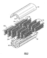
Figure 3 is an exploded view of the example ion exchange reactor. -
Figure 4 is an exploded view of an example cartridge for use in the ion exchange reactor. -
Figure 1 illustrates selected portions of anexample cooling system 10, such as an ultra-pure water cooling system. In this example, thecooling system 10 includes aheat exchanger 12 arranged within a cooling loop 14. The cooling loop 14 circulates a coolant, such as water, between theheat exchanger 12 and adevice 16 that the coolant maintains at a desired temperature. The cooling loop 14 employs anion exchange reactor 18 to maintain the coolant in a desired pure state. For example, theion exchange reactor 18 removes ions from the coolant to maintain a desired level of electrical resistivity and/or a desired coolant pH. It is to be understood that the above describedcoolant system 10 is an example, and that other types of systems will also benefit from theion exchange reactor 18. -
Figure 2 illustrates an example of theion exchange reactor 18, which includes anouter container 30 having aninlet 32 and anoutlet 34. Although thecontainer 30 is cylindrically shaped in this example, any number of different shapes may be used. Thecontainer 30 encloses at least onecartridge 36 for removing the ions from the coolant. In the illustrated example, a plurality of thecartridges 36 are used. However, it is to be understood that the number ofcartridges 36 may be varied depending upon the ion removal needs of a particular system. - Referring also to the exploded view in
Figure 3 , thecartridges 36 are spaced apart such that there arefluid passages 38 that extend between thecartridges 36. The amount of spacing between thecartridges 36 depends upon the desired ion removal performance, as will be described. Thecartridges 36 vary in size. For example, acartridge 36a located radially outwards from a centerline A of thecontainer 30 is smaller than acartridge 36b located closer to the centerline A. That is, thecartridge 36a includes less interfacial surface area exposed to thefluid passages 38 than thecartridge 36b. - The
container 30 includesstepped grooves 40 for retaining and positioning thecartridges 36. In this example, the stepped grooves 40 position a first set ofcartridges 36c parallel and end-to-end with a second set ofcartridges 36d. Alternatively, only one set ofcartridges 36 could be used, or a greater number than two sets of cartridges may be used, depending upon the ion removal needs of a particular system. - The
stepped grooves 40 also position thecartridges 36 approximately parallel to a flow direction 42 (Figure 2 ) through theion exchange reactor 18. Thus, thefluid passages 38 extend linearly between the ends of thecartridges 36 and provide little or no resistance to coolant flow between thecartridges 36. -
Figure 4 illustrates an exploded view of anexample cartridge 36. In this example, thecartridge 36 includes a frame 52. The frame is a rectangular ring defining an interior open space. It is to be understood however, that the shape of the frame 52 may vary from the disclosed example, depending upon design factors, such as the size requirements of a particular system. Optionally, the frame 52 also includes an opening 54 and aseal 56 that removably fits within the opening 54. Theopening 54 provides access the interior of the frame 52 to permit filling or removal of anion exchange media 58 into thecartridge 36. - A
porous screen 60 is attached on each planar side of the frame 52 betweenporous covers 62 that are secured to the frame 52. In this example,fasteners 64 extend through theporous covers 62 and into the frame 52 to secure theporous screens 60 between theporous covers 62 and the frame 52. Once assembled, the porous covers 62 andporous screen 60 permit water flow therethrough from thefluid passages 38 to theion exchange media 58. The porosity of theporous screens 60 and the porous covers 62 limits the flow of coolant into and out of thecartridge 36. - The
ion exchange media 58 includes an ion exchange resin. For example, the resin includes anionic active sites 66 and cationicactive sites 68 for, respectively, removing anions and cations from the coolant. Alternatively, theion exchange media 58 may be another type of ion exchange media suited for the particular system. - The
cartridges 36 and their arrangement within thecontainer 30 provide the benefit of an ion removal rate that varies with the concentration of the ions in the coolant. In the illustrated example, theopen fluid passages 38 between thecartridges 36 establish a diffusion distance for the ions to travel to theion exchange media 58. That is, for the ions to be removed from the coolant, the ions must move through the coolant within thefluid passages 38, through openings in theporous cover 62, through openings in theporous screen 60, and to anactive site 66, 68 of theion exchange media 58. The diffusion of ions per unit of time, or mass transfer, is proportional to the concentration and the interfacial surface area of thecartridges 36. That is, increasing concentration and interfacial surface area increases mass transfer. The inverse occurs for decreasing concentration and decreasing interfacial surface area. - At relatively higher concentrations, a portion of the ions diffuse into the
cartridges 36 for removal, which results in a relatively high ion removal rate that requires few passes through thereactor 18 to remove a significant amount of the ions. Conversely, at relatively lower concentrations, fewer ions diffuse into thecartridges 36 for removal, which results in a relatively low ion removal rate that requires many passes through thereactor 18 to remove remaining ions. The specific ion removal rates of a particular system will vary, depending on a variety of factors such as the types of ions, coolant flow rate, system corrosion etc. - The ion removal rate is also proportional to the interfacial surface area of the
cartridges 36. That is, the rates shift in proportion to the interfacial surface area. For example, if the arrangement in the disclosed example is changed such that thecartridges 36 are closer together, the size of thefluid passages 38 would decrease and the effective interfacial surface area of thecartridges 36 would increase. This would result in a shorter diffusion distance between thefluid passages 38 and theion exchange material 58, and a corresponding greater ion removal rate. Conversely, if thecartridges 36 were farther apart than in the illustrated example, the size of thefluid passages 38 would increase. This would result in a greater diffusion distance and a corresponding lower ion-removal rate. Thus, the spacing between thecartridges 36 at least partially determines the amount of effective interfacial surface area and can be designed to achieve a desired ion removal rate. For example, the spacing of thecartridges 36 can be predetermined through experimentation for desirable ion removal rates. - The variation in ion removal rate provides the benefit of establishing an equilibrium ion concentration level above zero rather than removing essentially all of the ions. At progressively lower concentrations, the ion removal rate approaches zero order and is too slow to remove the remaining ions. By allowing some of the ions to remain in the coolant, the electric resistivity and pH can be controlled to a desired level. For example, a particular equilibrium resistivity and pH may be achieved by using particular sizes and numbers of
cartridges 36 and by using a particular spacing ofcartridges 36. In the illustrated example, the electrical resistivity is maintained between 0.2 and 5.0 Mohm-cm during operation of thecoolant system 10. Controlling the electrical resistivity and the pH of the coolant provides the opportunity to tailor the electrical resistivity and pH of the coolant to thecoolant system 10. For example, incoolant systems 10 that utilize ultra pure water, it may be desirable to maintain the resistivity within the above range to prevent current leakage within thedevice 16 or elsewhere within thecoolant system 10. Similarly, controlling the pH to a desired level may provide better control over corrosion within thecoolant system 10. - The disclosed example
ion exchange reactor 18 provides the benefit of a relatively low pressure drop compared to previously known reactors, and the ability to control the electrical resistivity and pH of a coolant. For example, the open, linearfluid passages 38 allow relatively free flow of the coolant through theion exchange reactor 18 to thereby produce low pressure drop. Additionally, the arrangement of thecartridges 36 within thecontainer 30 permits variation of the ion removal rate such that theion exchange reactor 18 becomes more efficient in removing ions at high concentrations and less efficient in removing ions at low concentrations. - Although a combination of features is shown in the illustrated examples, not all of them need to be combined to realize the benefits of various embodiments of this disclosure. In other words, a system designed according to an embodiment of this disclosure will not necessarily include all of the features shown in any one of the Figures or all of the portions schematically shown in the Figures. Moreover, selected features of one example embodiment may be combined with selected features of other example embodiments.
- The preceding description is exemplary rather than limiting in nature. Variations and modifications to the disclosed examples may become apparent to those skilled in the art that do not necessarily depart from the essence of this disclosure. The scope of legal protection given to this disclosure can only be determined by studying the following claims.
Claims (19)
- An ion exchange apparatus (18) comprising:at least one fluid passage (38) extending between an inlet (32) and an outlet (34) for transporting a fluid having ions; andat least one cartridge (36) having an ion exchange material (58) therein, the at least one cartridge having an ion removal rate of removing the ions from the fluid, and the ion removal rate varies in response to a concentration of the ions in the fluid.
- The ion exchange apparatus recited in claim 1, wherein the ion removal rate varies in proportion to a concentration of the ions in the fluid and in proportion to an interfacial surface area of the at least one cartridge (36) with the at least one fluid passage (38).
- The ion exchange apparatus recited in claim 1 or 2, wherein the at least one fluid passage (38) is coextensive with the at least one cartridge (36).
- The ion exchange apparatus recited in claim 1, 2 or 3, wherein the at least one cartridge (36) comprises two cartridges (36a, b) and the at least one fluid passage (38) is located between the two cartridges.
- The ion exchange apparatus recited in claim 1, 2, 3 or 4, wherein the at least one fluid passage (38) extends linearly between ends of the at least one cartridge (36).
- The ion exchange apparatus recited in any preceding claim, wherein the at least one ion exchange cartridge (36) includes a plurality of cartridges (36a, b) that vary in size.
- The ion exchange apparatus recited in any preceding claim, wherein the ion exchange material (58) includes anionic active sites (66) and cationic active sites (68).
- The ion exchange apparatus recited in any preceding claim, wherein the at least one cartridge (36) includes a porous outer structure (60, 62) and the ion exchange material (58) is contained within the porous outer structure.
- The ion exchange apparatus recited in claim 8, wherein the porous outer structure includes a first planar porous screen (60) and a second planar porous screen (60) spaced apart from the first planar porous screen.
- The ion exchange apparatus recited in claim 8 or 9, wherein the at least one cartridge (36) includes a frame (52) supporting the porous outer structure (60, 62).
- The ion exchange apparatus recited in claim 10, wherein the frame includes a port (54) and removable seal (56) receivable within the port.
- The ion exchange apparatus recited in claim 8, 9, 10 or 11, wherein the at least one cartridge (36) includes a rectangular annular frame (52).
- The ion exchange apparatus recited in claim 12, further comprising a first porous cover (62) secured to one side of the rectangular annular frame (52), and a second porous cover (62) secured to the opposite side of the rectangular annular frame (52).
- An ion exchange apparatus (18) comprising:a plurality of spaced-apart cartridges (36) each having an ion exchange material (58) therein; anda plurality of fluid passages (38) for transporting a fluid having ions, each of the plurality of fluid passages extending between corresponding ones of the plurality of spaced-apart cartridges (36).
- The ion exchange cartridge recited in claim 14, wherein the plurality of spaced-apart cartridges (36) includes a first cartridge (36a) having a first size and a second cartridge (36b) having a second size that is different from the first size.
- The ion exchange cartridge recited in claim 14, wherein each of the plurality of spaced-apart cartridges (36) is oriented parallel to a fluid flow direction (42) between an inlet (32) and an outlet (34).
- A method of controlling ion removal from a fluid flowing through an ion exchange apparatus (18), the method comprising:(a) providing at least one cartridge (36) having an ion exchange material (58) contained therein, and at least one fluid passage (38) coextensive with the at least one ion exchange cartridge (36);(b) establishing a first ion removal rate of the at least one cartridge (36) when a concentration of ions in the fluid is at a first ion concentration; and(c) establishing a second, lower ion removal rate of the at least one cartridge (36) when the concentration of ions in the fluid is at a second, lower ion concentration.
- The method recited in claim 17, further comprising establishing a non-zero equilibrium of ions within the fluid.
- The method recited in claim 17 or 18, further comprising establishing an equilibrium electric resistivity of the fluid between 0.2 and 5.0 Mohm-cm.
Applications Claiming Priority (1)
| Application Number | Priority Date | Filing Date | Title |
|---|---|---|---|
| US11/708,811 US7857979B2 (en) | 2007-02-21 | 2007-02-21 | Ion exchange reactor |
Publications (2)
| Publication Number | Publication Date |
|---|---|
| EP1961483A1 true EP1961483A1 (en) | 2008-08-27 |
| EP1961483B1 EP1961483B1 (en) | 2014-10-15 |
Family
ID=39431094
Family Applications (1)
| Application Number | Title | Priority Date | Filing Date |
|---|---|---|---|
| EP08250615.5A Active EP1961483B1 (en) | 2007-02-21 | 2008-02-21 | Ion exchange reactor |
Country Status (3)
| Country | Link |
|---|---|
| US (1) | US7857979B2 (en) |
| EP (1) | EP1961483B1 (en) |
| JP (1) | JP2008200673A (en) |
Cited By (1)
| Publication number | Priority date | Publication date | Assignee | Title |
|---|---|---|---|---|
| EP2664588A1 (en) * | 2012-05-17 | 2013-11-20 | Hamilton Sundstrand Space Systems International, Inc. | Low pressure drop remediation bed for water based coolant loops |
Citations (5)
| Publication number | Priority date | Publication date | Assignee | Title |
|---|---|---|---|---|
| US4430226A (en) | 1981-03-09 | 1984-02-07 | Millipore Corporation | Method and apparatus for producing ultrapure water |
| EP0563321A1 (en) | 1990-12-17 | 1993-10-06 | Ionpure Techn Corp | Electrodeionization apparatus. |
| WO1997029048A1 (en) | 1996-02-09 | 1997-08-14 | United States Filter Corporation | Method and apparatus for purifying water |
| WO2001021269A2 (en) | 1999-09-23 | 2001-03-29 | Edison Termoelettrica S.P.A. | Carbon dioxide absorption unit and regeneration method for said unit |
| US20050115884A1 (en) | 2003-11-28 | 2005-06-02 | Toyo Roki Seizo Kabushiki Kaisha | Ion-exchange filter |
Family Cites Families (16)
| Publication number | Priority date | Publication date | Assignee | Title |
|---|---|---|---|---|
| US2091002A (en) * | 1935-02-11 | 1937-08-24 | Permutit Co | Water softening device |
| US2126365A (en) * | 1935-11-02 | 1938-08-09 | Demetrios G Alexopoulos | Washing machine |
| US3073505A (en) | 1960-06-15 | 1963-01-15 | Boas Box Company | Folding gift box |
| US3186941A (en) * | 1962-08-02 | 1965-06-01 | Dow Chemical Co | Water softening with fine cation exchange tubes |
| US3664095A (en) * | 1968-10-21 | 1972-05-23 | Gunnar C F Asker | Exchange packing element |
| JPH0299187A (en) | 1988-10-06 | 1990-04-11 | Nec Corp | Water purification device |
| US5082568A (en) | 1989-03-17 | 1992-01-21 | Ametek, Inc. | Method for removing low concentrations of metal contaminants from water |
| US5073502A (en) | 1990-06-27 | 1991-12-17 | United Technologies Corporation | Method and apparatus for analyzing total organic halogens |
| US5151194A (en) | 1990-10-31 | 1992-09-29 | Hydrocarbon Filtration Systems, Inc. | Filter for removing liquid hydrocarbons from water and process of removing gaseous and/or hydrocarbons from water |
| US5518626A (en) | 1993-12-23 | 1996-05-21 | United Technologies Corporation | Process employing thermally sterilizable aqueous polishing agents |
| US5525237A (en) | 1993-12-23 | 1996-06-11 | United Technologies Corporation | Process for removing free and dissolved CO2 from aqueous solutions |
| US6290847B1 (en) | 1998-12-17 | 2001-09-18 | Corning Incorporated | Gravity-flow water filtration device |
| US6454941B1 (en) | 1998-12-17 | 2002-09-24 | Corning Incorporated | Gravity-flow water filtration device |
| US7025884B2 (en) | 2000-11-10 | 2006-04-11 | Ch2M Hill, Inc. | Method and apparatus for treatment of a fluid system |
| JP2005169361A (en) | 2003-12-15 | 2005-06-30 | Mitsubishi Chemicals Corp | Cooling system, desalinator and desalting member, and computer and battery equipped with cooling system |
| US7368059B2 (en) * | 2004-02-09 | 2008-05-06 | Drake Engineering Incorporated | Method for preferentially removing monovalent cations from contaminated water |
-
2007
- 2007-02-21 US US11/708,811 patent/US7857979B2/en active Active
-
2008
- 2008-02-18 JP JP2008035476A patent/JP2008200673A/en active Pending
- 2008-02-21 EP EP08250615.5A patent/EP1961483B1/en active Active
Patent Citations (5)
| Publication number | Priority date | Publication date | Assignee | Title |
|---|---|---|---|---|
| US4430226A (en) | 1981-03-09 | 1984-02-07 | Millipore Corporation | Method and apparatus for producing ultrapure water |
| EP0563321A1 (en) | 1990-12-17 | 1993-10-06 | Ionpure Techn Corp | Electrodeionization apparatus. |
| WO1997029048A1 (en) | 1996-02-09 | 1997-08-14 | United States Filter Corporation | Method and apparatus for purifying water |
| WO2001021269A2 (en) | 1999-09-23 | 2001-03-29 | Edison Termoelettrica S.P.A. | Carbon dioxide absorption unit and regeneration method for said unit |
| US20050115884A1 (en) | 2003-11-28 | 2005-06-02 | Toyo Roki Seizo Kabushiki Kaisha | Ion-exchange filter |
Cited By (3)
| Publication number | Priority date | Publication date | Assignee | Title |
|---|---|---|---|---|
| EP2664588A1 (en) * | 2012-05-17 | 2013-11-20 | Hamilton Sundstrand Space Systems International, Inc. | Low pressure drop remediation bed for water based coolant loops |
| US9096444B2 (en) | 2012-05-17 | 2015-08-04 | Hamilton Sundstrand Space Systems International, Inc. | Low pressure drop remediation bed for water based coolant loops |
| US9394185B2 (en) | 2012-05-17 | 2016-07-19 | Hamilton Sundstrand Space Systems International, Inc. | Low pressure drop remediation bed for water based coolant loops |
Also Published As
| Publication number | Publication date |
|---|---|
| US7857979B2 (en) | 2010-12-28 |
| US20080197080A1 (en) | 2008-08-21 |
| JP2008200673A (en) | 2008-09-04 |
| EP1961483B1 (en) | 2014-10-15 |
Similar Documents
| Publication | Publication Date | Title |
|---|---|---|
| EP4163578B1 (en) | Cold plate and a method of manufacture thereof | |
| KR100581984B1 (en) | Tank processing assembly | |
| US7387729B2 (en) | Filter cartridge for a standalone point of use water purification device | |
| EP2767514A1 (en) | Ion exchanger and cooling device equipped with ion exchanger | |
| WO2017199092A1 (en) | Filter for immersion cooling apparatus | |
| JP6437259B2 (en) | Ion exchanger | |
| EP2693152A1 (en) | In-line ultrapure heat exchanger | |
| WO2018142310A1 (en) | Liquid cooling systems for heat generating devices | |
| JP5375175B2 (en) | Ion exchanger | |
| US7857979B2 (en) | Ion exchange reactor | |
| JP4504817B2 (en) | Flow directing insert and reactor for a reactor chamber | |
| ES2205478T3 (en) | SOLID SEPARATION APPARATUS CONTAINED IN A LIQUID. | |
| CN107107015B (en) | Methods and apparatus for cross-flow reactors | |
| EP2664588B1 (en) | Low pressure drop remediation bed for water based coolant loops | |
| KR20050022245A (en) | Liquid cooled system and electronic appliance using the same | |
| CN213132241U (en) | A filter core and whole room drainage system for whole room drainage system | |
| JP6459661B2 (en) | Fuel cell cooling system | |
| KR20230165414A (en) | Cold water generating apparatus | |
| JP6862319B2 (en) | Ion exchanger | |
| JP3517334B2 (en) | Reactor | |
| KR20250132042A (en) | Cold water generating apparatus | |
| JP2016082658A (en) | Cooling structure of rotating electric machine | |
| US3337054A (en) | Filter apparatus | |
| EP3193062B1 (en) | Valve arrangement and insert for a valve arrangement | |
| CN107664456B (en) | Metal hydride reactor |
Legal Events
| Date | Code | Title | Description |
|---|---|---|---|
| PUAI | Public reference made under article 153(3) epc to a published international application that has entered the european phase |
Free format text: ORIGINAL CODE: 0009012 |
|
| AK | Designated contracting states |
Kind code of ref document: A1 Designated state(s): AT BE BG CH CY CZ DE DK EE ES FI FR GB GR HR HU IE IS IT LI LT LU LV MC MT NL NO PL PT RO SE SI SK TR |
|
| AX | Request for extension of the european patent |
Extension state: AL BA MK RS |
|
| 17P | Request for examination filed |
Effective date: 20081125 |
|
| 17Q | First examination report despatched |
Effective date: 20090123 |
|
| AKX | Designation fees paid |
Designated state(s): DE FR GB |
|
| REG | Reference to a national code |
Ref country code: DE Ref legal event code: R079 Ref document number: 602008034873 Country of ref document: DE Free format text: PREVIOUS MAIN CLASS: B01J0047020000 Ipc: B01J0047120000 |
|
| GRAP | Despatch of communication of intention to grant a patent |
Free format text: ORIGINAL CODE: EPIDOSNIGR1 |
|
| RIC1 | Information provided on ipc code assigned before grant |
Ipc: C02F 1/66 20060101ALN20140624BHEP Ipc: B01J 47/12 20060101AFI20140624BHEP Ipc: B01J 47/04 20060101ALI20140624BHEP Ipc: C02F 1/42 20060101ALI20140624BHEP Ipc: B01J 47/02 20060101ALI20140624BHEP |
|
| INTG | Intention to grant announced |
Effective date: 20140707 |
|
| GRAS | Grant fee paid |
Free format text: ORIGINAL CODE: EPIDOSNIGR3 |
|
| GRAA | (expected) grant |
Free format text: ORIGINAL CODE: 0009210 |
|
| AK | Designated contracting states |
Kind code of ref document: B1 Designated state(s): DE FR GB |
|
| REG | Reference to a national code |
Ref country code: GB Ref legal event code: FG4D |
|
| REG | Reference to a national code |
Ref country code: DE Ref legal event code: R096 Ref document number: 602008034873 Country of ref document: DE Effective date: 20141127 |
|
| REG | Reference to a national code |
Ref country code: DE Ref legal event code: R097 Ref document number: 602008034873 Country of ref document: DE |
|
| PLBE | No opposition filed within time limit |
Free format text: ORIGINAL CODE: 0009261 |
|
| STAA | Information on the status of an ep patent application or granted ep patent |
Free format text: STATUS: NO OPPOSITION FILED WITHIN TIME LIMIT |
|
| REG | Reference to a national code |
Ref country code: DE Ref legal event code: R119 Ref document number: 602008034873 Country of ref document: DE |
|
| 26N | No opposition filed |
Effective date: 20150716 |
|
| REG | Reference to a national code |
Ref country code: FR Ref legal event code: PLFP Year of fee payment: 9 |
|
| PG25 | Lapsed in a contracting state [announced via postgrant information from national office to epo] |
Ref country code: DE Free format text: LAPSE BECAUSE OF NON-PAYMENT OF DUE FEES Effective date: 20150901 |
|
| REG | Reference to a national code |
Ref country code: FR Ref legal event code: PLFP Year of fee payment: 10 |
|
| REG | Reference to a national code |
Ref country code: FR Ref legal event code: PLFP Year of fee payment: 11 |
|
| P01 | Opt-out of the competence of the unified patent court (upc) registered |
Effective date: 20230522 |
|
| PGFP | Annual fee paid to national office [announced via postgrant information from national office to epo] |
Ref country code: GB Payment date: 20260121 Year of fee payment: 19 |
|
| PGFP | Annual fee paid to national office [announced via postgrant information from national office to epo] |
Ref country code: FR Payment date: 20260121 Year of fee payment: 19 |