EP1961446A1 - Radiation therapy apparatus - Google Patents
Radiation therapy apparatus Download PDFInfo
- Publication number
- EP1961446A1 EP1961446A1 EP08003140A EP08003140A EP1961446A1 EP 1961446 A1 EP1961446 A1 EP 1961446A1 EP 08003140 A EP08003140 A EP 08003140A EP 08003140 A EP08003140 A EP 08003140A EP 1961446 A1 EP1961446 A1 EP 1961446A1
- Authority
- EP
- European Patent Office
- Prior art keywords
- leaf
- leaves
- collimator
- radiation therapy
- therapy apparatus
- Prior art date
- Legal status (The legal status is an assumption and is not a legal conclusion. Google has not performed a legal analysis and makes no representation as to the accuracy of the status listed.)
- Granted
Links
Images







Classifications
-
- G—PHYSICS
- G21—NUCLEAR PHYSICS; NUCLEAR ENGINEERING
- G21K—HANDLING OF PARTICLES OR IONISING RADIATION NOT OTHERWISE PROVIDED FOR; IRRADIATION DEVICES; GAMMA RAY OR X-RAY MICROSCOPES
- G21K1/00—Arrangements for handling particles or ionising radiation, e.g. focusing or moderating
- G21K1/02—Arrangements for handling particles or ionising radiation, e.g. focusing or moderating using diaphragms, collimators
- G21K1/04—Arrangements for handling particles or ionising radiation, e.g. focusing or moderating using diaphragms, collimators using variable diaphragms, shutters, choppers
- G21K1/046—Arrangements for handling particles or ionising radiation, e.g. focusing or moderating using diaphragms, collimators using variable diaphragms, shutters, choppers varying the contour of the field, e.g. multileaf collimators
-
- A—HUMAN NECESSITIES
- A61—MEDICAL OR VETERINARY SCIENCE; HYGIENE
- A61N—ELECTROTHERAPY; MAGNETOTHERAPY; RADIATION THERAPY; ULTRASOUND THERAPY
- A61N5/00—Radiation therapy
- A61N5/10—X-ray therapy; Gamma-ray therapy; Particle-irradiation therapy
- A61N5/1042—X-ray therapy; Gamma-ray therapy; Particle-irradiation therapy with spatial modulation of the radiation beam within the treatment head
- A61N5/1045—X-ray therapy; Gamma-ray therapy; Particle-irradiation therapy with spatial modulation of the radiation beam within the treatment head using a multi-leaf collimator, e.g. for intensity modulated radiation therapy or IMRT
-
- A—HUMAN NECESSITIES
- A61—MEDICAL OR VETERINARY SCIENCE; HYGIENE
- A61N—ELECTROTHERAPY; MAGNETOTHERAPY; RADIATION THERAPY; ULTRASOUND THERAPY
- A61N5/00—Radiation therapy
- A61N5/10—X-ray therapy; Gamma-ray therapy; Particle-irradiation therapy
- A61N5/1048—Monitoring, verifying, controlling systems and methods
-
- G—PHYSICS
- G21—NUCLEAR PHYSICS; NUCLEAR ENGINEERING
- G21K—HANDLING OF PARTICLES OR IONISING RADIATION NOT OTHERWISE PROVIDED FOR; IRRADIATION DEVICES; GAMMA RAY OR X-RAY MICROSCOPES
- G21K1/00—Arrangements for handling particles or ionising radiation, e.g. focusing or moderating
- G21K1/02—Arrangements for handling particles or ionising radiation, e.g. focusing or moderating using diaphragms, collimators
- G21K1/04—Arrangements for handling particles or ionising radiation, e.g. focusing or moderating using diaphragms, collimators using variable diaphragms, shutters, choppers
Definitions
- the present invention relates to a radiation therapy apparatus used for a therapy of diseases such as malignant tumors, and particularly to the radiation therapy apparatus including a multi-leaf collimator device which allows an extent of an object that is exposed to radiation (which will be referred to as an "irradiation field" hereafter) to be set with high precision.
- a radiation therapy apparatus used for a therapy of diseases such as malignant tumors
- the radiation therapy apparatus including a multi-leaf collimator device which allows an extent of an object that is exposed to radiation (which will be referred to as an "irradiation field" hereafter) to be set with high precision.
- the radiation therapy apparatus includes a collimator device formed of a material the nature of which renders it impermeable to radiation such as tungsten or the like, thereby allowing the exposure to radiation to be limited to a therapy part including a body.
- a collimator device needs to have a function of carefully forming the irradiation field that approximates a shape of the therapy part without a formation of a penumbra. Accordingly, such a collimator device has a; first collimator and a second collimator arranged in the irradiation direction such that they overlap.
- the first collimator provided on a near side of a radiation source is configured in a form of a single unit comprising a pair of members disposed such that they face each other across an irradiation axis.
- the members drive so as to adjust a distance therebetween.
- the members drive along an arc-shaped path around the radiation source as a center.
- the second collimator provided on a far side of the radiation source is configured in the form of a pair of collimator components (blocks) such that the collimator components face each other across the irradiation axis in an orthogonal direction to a moving direction of the first collimator.
- Each of the collimator components of the second collimator has multiple leaves arranged close to one another, which can be individually moved so as to adjust a distance therebetween along the arc-shaped path around the radiation source as the center.
- the second collimator is called “multi-leaf collimator", which includes, for example, a block pair composed of several ten leaves that are closely gathered side by side.
- the leaves of the second collimator each have the arc-shaped path and are individually driven movably along the arc-shaped path with a driving device provided to each leaf.
- the radiation field of an irregular shape can be formed by combining an operation of moving the first collimator composed of a pair of opposing separate members to get close to/away from each other in an X direction and an operation of individually moving the leaves of the second collimator, which are gathered opposite to each other, so as to get close to/away from each other in a Y direction.
- the first collimator and the second collimator may be collectively referred to as "multi-leaf collimator".
- Fig. 15 schematically is one leaf 41 of the second collimator and a driving device 43 for driving the leaf. Referring to Fig. 15 , how to drive the leaf 41 and control its position is described below in brief.
- the leaf 41 of Fig. 15 is formed in a fan shape that converges to a radiation source as seen in a plan view and in a plate-like or wedge shape as seen in a side view. Further, an outer edge 41a of the leaf 41 is curved along the arc-shaped path around the radiation source as the center. A gear tooth is cut in the arc-shaped path plane, that is, the curved outer edge 41a. A driving gear 43a is engaged with the tooth of the outer edge 41a.
- the driving gear 43a is fixed to a tip end of a shaft 43b.
- the shaft 43b is driven based on a driving force transmitted from a motor 43c as a driving source through a driving force transmitting mechanism such as a worm gear 43d.
- a potentiometer 43e and an encoder 43f are arranged to detect a torque, and function as a position detecting device for the leaf 41.
- the motor 43c is controlled by an additional control device based on information from the potentiometer 43e and the encoder 43f, and the leaf 41 is set in a desired position to form a predetermined radiation field (see "Japanese Patent Publication (Laid-open: KOKAI) No. 2002-253686", for example).
- leaves of the multi-leaf collimator can be moved closer to/away from each other in a horizontal direction without requiring a complicated structure such as moves the leaves concentrically along the arc-shaped path around the radiation source as the center.
- One known technique applicable to this case is to drive a threaded shaft connected to each leaf with a motor through a flexible cable (see “Japanese Patent No. 2543373 ", for example).
- Japanese Patent Publication No. 2002-253686 requires a mechanism for transmitting a torque of a motor to each of leaves of the second collimator through various gears and a shaft in order to individually move the leaves.
- Such a driving force transmitting mechanism needs to be provided to each leaf.
- radioprotection in recent years, there is an increasing demand to further match a radiation field to an irregular shape of a treated area. To meet the demand, it has been examined whether to increase the number of leaves.
- Japanese Patent No. 2543373 transmits a torque of the motor to the threaded shaft connected to each leaf through a flexible cable to move the leaves by pushing or pulling in a horizontal direction.
- the flexible cable extends or contracts, resulting in a problem that the moving of each leaf cannot be managed with accuracy.
- the present invention has taken into consideration the above-described problems and it is an object of the present invention to provide the radiation therapy apparatus which a torque wire having a high rotation following allows transmission of a torque of the motor as a driving source to a tip end with accuracy while keeping a high flexibility to a bent portion. Accordingly, the torque wire transmits a torque of the motor to a driving gear with accuracy regardless of orientation and angle of the motor, making it possible to move the leaves concentrically along the arc-shaped path about the radiation source to get close to/away from each other.
- the motor achieves the very high degree of freedom of arrangement relative to the moving axis of the leaves and is placed in a dead space in the collimator.
- an internal space of the collimator device is efficiently utilized, and the number of leaves is increased without enlarging the collimator device.
- the irradiation field is matched more with a treatment site without reducing the space for the treatment, so as to enable safer radiotherapy for the object.
- the driving gear of the driving device is a one-stage gear, so backlash is easily adjusted and operation accuracy is improved.
- the present invention has taken into consideration the above-described problems and it is an object of the present invention to provide the radiation therapy apparatus which the moving amount of each leaf is easily detected using a torque motor with a built-in encoder, making it to simplify a complicated mechanism using a number of gears, and a potentiometer or an encoder in combination to control the moving amount.
- the present invention has taken into consideration the above-described problems and it is an object of the present invention to provide the radiation therapy apparatus which a displacement or position detection error due to an influence of backlash or friction between gears is suppressed. Hence, a leaf position is accurately detected and the irradiation field is accurately matched with an affected area.
- the present invention provides the radiation therapy apparatus, comprising: a multi-leaf collimator device having a pair of collimator components which respectively comprise a plurality of leaves arranged close to one another such that the leaves face one another across an irradiation axis, and configured to set a desired irradiation field by individually moving the leaves; a driving gear engaged with a gear tooth of the each leaf, respectively; a torque wire connected to a shaft center of the driving gear, respectively; and a driving unit configured to drive the driving gears through the torque wire.
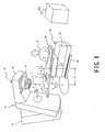
- Fig. 1 is an external view which shows a usage condition of the radiation therapy apparatus according to a present embodiment. First, description will be made in a schematic fashion with reference to Fig. 1 regarding a configuration of the radiation therapy apparatus according to the present embodiment.
- the radiation therapy apparatus has an irradiation device 10 which uses a radiation source to irradiate a predetermined direction, a therapy table 20 on which an object (a person who needs a therapy) P, including a focus, lies and which sets a positioning of a therapy part to be irradiated, and a control device 30 which organically controls a components of the radiation therapy apparatus, e.g., the irradiation device 10 and the therapy table 20.
- a control device 30 which organically controls a components of the radiation therapy apparatus, e.g., the irradiation device 10 and the therapy table 20.
- the irradiation device 10 includes a fixed frame 11 installed on a floor, a turnable frame 12 which is turnably supported by the fixed frame 11, an irradiation head 13 provided to a tip portion extending in the horizontal direction from one end of the turnable frame 12, and a collimator device 14 which is a built-in component of the irradiation head 13.
- the turnable frame 12 can be turned with respect to the fixed frame 11 over approximately 360 degrees around a rotation center axis "H" extending in the horizontal direction.
- the collimator device 14 is provided such that it can be turned with respect to the irradiation head 13 around an irradiation axis "I".
- the turnable frame 12 is configured such that it can be turned according to various kinds of irradiation, examples of which include a rotation irradiation, a pendulum irradiation, an intermittent irradiation, etc.
- the therapy table 20 is installed on the floor such that it can be turned over a predetermined angle range in a direction of arrow "G" along an arc with the isocenter IC as a center. Furthermore, a table-top 22, on which the object P can lie, is provided to a top of the therapy table 20.
- the table-top plate 22 is supported by an upper portion mechanism 21.
- the upper portion mechanism 21 includes a mechanism which allows the table-top 22 to be moved in a longitudinal direction indicated by an arrow "e"' and a lateral direction indicated by an arrow "f".
- the upper portion mechanism 21 is supported by an elevator mechanism 23.
- the elevator mechanism 23 has a link mechanism, for example. Such an arrangement allows the elevator mechanism 23 itself to be moved in a vertical direction indicated by an arrow "d", thereby allowing the upper portion mechanism 21 and the table-top 22 to be moved in a predetermined range in the vertical direction.
- the elevator mechanism 23 is supported by a lower portion mechanism 24.
- the lower portion mechanism includes a mechanism which allows the elevator mechanism 23 to be turned in the direction indicated by an arrow "F", with the position that is distant from the isocenter IC by a distance "L" as the center.
- Such an arrangement allows the upper portion mechanism 21 and the table-top 22 to be turned in a predetermined range of angle in the direction indicated by the arrow "F", in addition to the elevator mechanism 23.
- the collimator device 14 controls a position to be irradiated, which protects the normal tissue from being exposed to radiation.
- the collimator device 14 is provided in the form of a built-in component of the irradiation head 13 such that it can be turned around the irradiation axis "I".
- Fig. 2 is a side view, shown a driving direction of a second collimator 141 as a depth direction, which shows a first collimator 140 and the second collimator 141 included the collimator device 14 in the present embodiment.
- Fig. 3 is a side view, shown a first example of the driving direction of the second collimator 141 as an orthogonal direction, which shows the first collimator 140 and the second collimator 141 provided to the collimator device 14 in the present embodiment.
- Fig. 2 is a side view, shown a driving direction of a second collimator 141 as a depth direction, which shows a first collimator 140 and the second collimator 141 included the collimator device 14 in the present embodiment.
- Fig. 3 is a side view, shown a first example of the driving direction of the second collimator 141 as an orthogonal direction, which shows the first collimator 140 and the second collimator 141 provided to the collimator device 14 in the present embodiment.
- FIG. 4 is a side view, shown a second example of the driving direction of the second collimator 141 as an orthogonal direction, which shows the first collimator 140 and the second collimator 141 provided to the collimator device in the present embodiment.
- Fig. 3 and Fig. 4 show the collimator device 14 viewed in an orthogonal direction orthogonal to the direction in which the collimator 14 shown in Fig. 2 is viewed.
- a housing of the collimator device 14 is not shown in these drawings.
- Fig. 5 is a top view which shows a constitution example of the second collimator provided to the collimator device 14 in the present embodiment.
- the collimator device 14 has two kinds of collimators (a first collimator 140 and a second collimator 141) formed of a heavy metal such as tungsten or the like. These two kinds of collimators are arranged along the irradiation direction from the radiation source "S" such that they overlap. With such an arrangement, each of the collimators 140 and 141 has a pair of separate components arranged such that they face each other (see the components denoted by reference numerals 140A, 140B, 141A, and 141B in Fig. 2 and Fig. 3 ).
- such a pair of components forming the collimator 140 or 141 is differentiated by reference symbols "A" and "B" for convenience of understanding.
- each of the first collimator component 140A and the second collimator component 140B provided on a near side of the radiation source "S" is configured in the form of a single unit, as clearly shown in Fig. 2 .
- the collimator components 140A and 140B are arranged such that an end face of the collimator component 140A and an end face of the collimator component 140B face each other across the irradiation axis "I".
- Such an arrangement allows the collimator elements 140A and 140B to be moved in a direction of an arrow "X" along an arc-shaped path around the radiation source "S" as a center by driving devices 142A and 142B, thereby adjusting a distance between the collimator components 140A and 140B.
- the second collimator components 141A and 141B provided on a far side of the radiation source "S" can be moved along the arc-shaped path, as clearly shown in Fig. 3 .
- the collimator components 141A and 141B are arranged such that an end face of the collimator component 141A and an end face of the collimator component 141B face each other across the irradiation axis "I".
- Such an arrangement allows the collimator elements 141A and 141B to be moved by driving devices 143A and 143B in the orthogonal direction to the aforementioned arranging direction of the collimator elements 140A and 140B, i.e., in a direction of ;an arrow "Y" along the arc-shaped path around the radiation source "S" as the center, thereby adjusting a distance between the collimator components 141A and 141B.
- the second collimator components 141A and 141B are arranged such that the end face of the collimator component 141A and the end face of the collimator component 141B face each other across the irradiation axis "I".
- Such an arrangement allows the collimator elements 141A and 141B to be moved by the driving devices 143A and 143B in the orthogonal direction to an arranging direction of the first collimator elements 140A and 140B, i.e., in the direction of the arrow "Y" along a straight path, thereby adjusting the distance between the collimator components 141A and 141B.
- the second collimator component 141A (141B) has multiple leaves 141A1 - 141An (141B1 - 141Bn) arranged close to one another.
- Fig. 5 shows the detailed configuration thereof.
- driving devices 143A1 - 143An are provided to the respective leaves 141A1 - 141An (141B1 - 141Bn) forming the second collimator component 141A (141B).
- Such an arrangement allows the leaves 141A1 - 141n (141B1 - 141Bn) to be driven individually in the direction of the arrow "Y" along the arc-shaped path around the radiation source "S" as the center, thereby adjusting the distances therebetween.
- Such an arrangement allows the leaves 141A1 - 141An of the second collimator component 141A and the leaves 141B1 - 141Bn of the second collimator component 141B to be moved individually in the "Y" direction so as to adjust the distance therebetween, in addition to allowing the first collimator components 140A and 140B to be moved in the "X" direction so as to adjust the distance therebetween.
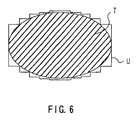
- the combination of these operations allows the irradiation field "U", shown in Fig. 6 , to be formed in a desired shape such that it approximates the shape of the therapy part "T" which is approximately equal to the focus.
- Fig. 7 shows an example of the driving device 143 such as the driving devices 143A1 - 143An and 1431B1 - 143Bn for driving the leaf 141 such as the leaves 141A1 - 141An and 141B1 - 141Bn.
- the leaves 141A1 - 141An and 141B1 - 141Bn of the second collimator components 141A and 141B are similar to conventional ones.
- the leaves are formed in a fan shape that converges to the radiation source as seen in a plan view and in a plate-like or wedge shape as seen in a side view.
- an outer edge of each leaf 141 is curved along the arc-shaped path around the radiation source "S" as the center.
- a gear tooth 141a is cut in the arc-shaped path plane, that is, the curved outer edge.
- a driving gear 143a of each of the driving devices 143A1 - 143An and 1431B1 - 143Bn (hereinafter simply referred to as “driving device 143") is engaged with the tooth 141a of the outer edge.
- the driving device 143 is composed of the driving gear 143a, a torque wire 143b, and a torque motor 143c. That is, the driving device is structured such that one end of the torque wire 143b is connected to the rotation center of the driving gear 143a engaged with the tooth 141a of the outer edge of the leaf 141, and the other end of the torque wire 143b is connected to the torque motor 143c. Thus, a torque of the torque motor 143c is transmitted to the driving gear 143a through the torque wire 143b to drive the leaf 141.
- a feature of the torque wire 143b is as follows. That is, the wire has a high rotation following capability and thus, can transmit a torque of a driving force such as a motor to a tip end with accuracy. In addition, the wire has flexibility and thus can keep its high performance even at a bent portion.
- the torque wire 143b can transmit a torque of the torque motor 143c to the driving gear 143a with accuracy irrespective of orientation and angle of the torque motor 143c, and can move each leaf 141 by a desired amount.
- the leaf 141 of the second collimator components 141A and 141B can be moved concentrically about the radiation source along the arc-shaped path to get close to/away from each other.
- the three torque motors 143c illustrated in Fig. 8 means that one torque motor 143c is arranged in different directions and at different angles by use of the torque wire 143b, not that the number of motors is three.
- the motor 143 achieves the very high degree of freedom of arrangement relative to the moving axis of each leaf 141 and thus can be placed even in a dead space of a container of the collimator 14.
- an internal space of the collimator can be efficiently utilized, and the number of leaves can be increased without enlarging the collimator 14.
- an irradiation field can be more matched with a treatment site without reducing a space for the therapy. This enables safer radiotherapy for the object.
- the driving gear 143a of the driving device 143 may be a one-stage gear, so backlash can be easily adjusted and operation accuracy can be improved.
- Fig. 9 is a top view of the leaves, which shows an arrangement example of the driving devices 143.
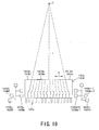
- Fig. 10 is a side view of the leaves, which shows an arrangement example of the driving devices 143.
- the driving devices 143 area arranged as shown in Figs. 9 and 10 , so the motor 143 achieves the very high degree of freedom of arrangement relative to the moving axis of each leaf 141 and thus can be placed even in a dead space of the container of the collimator 14.
- the torque motor 143c is equipped with an encoder, moving amounts of each leaf 141 can be easily detected, making it possible to simplify a complicated mechanism using a number of gears, and a potentiometer 43e or an encoder 43f in combination as shown in Fig. 15 to control the moving amounts.
- a laser beam disclosed in "Japanese Patent Publication (Laid-open: KOKAI) No. 2004-275243 " may be used to directly detect the moving amounts of each leaf 141 so as to set a position of each leaf 141.
- the radiation therapy apparatus of this embodiment as shown in Figs. 11 to 13 may include a leaf 141' attached to the above leaf 141 and having a predetermined pattern 200 along its outer circumference, and a moving amount detecting unit 201 for detecting plural positions of the leaf 141' based on the pattern 200 to detect the moving amounts of the leaf 141'.
- the detected moving amount of the leaf 141' is fed back to the control device 30.
- the moving amount detecting unit 201 includes a light irradiation unit 202, an imaging unit (image sensor) 203, and a moving amount calculating unit 204.
- the light irradiating unit 202 secured in a predetermined position is composed of a light emitting diode etc. and applies light to a fixed point "F" on the moving path of the leaf 141 so as to illuminate a part of the pattern formed on the leaf 141'.
- the image sensor 203 secured in a predetermined position is composed of a CCD (charge coupled device) camera etc. and obtains an image in an area including the fixed point "F" to obtain a fixed-point image.
- CCD charge coupled device
- the moving amount calculating unit 204 calculates the moving amount of the leaf 141' based on plural fixed-point images obtained with the image sensor 203.
- the moving amount of the leaf 141' can be directly detected with the moving amount detecting unit 201 in a non-contact fashion, so a displacement or position detection error due to an influence of backlash or friction between gears can be suppressed.
- any general motor not a motor with a built-in encoder, can be used.
- Fig. 11 schematically is the moving amount detecting unit 201 with respect to the leaf 141'.
- Fig. 12 is a sectional side view of the leaf 141', which elaborates on Fig. 11 .
- Fig. 13 shows a pattern example formed on the leaf 141'.
- the light irradiating unit 202 illuminates the fixed point "F" on the moving path of the leaf 141, for example, on the moving path of the arc-shaped outer edge of the leaf 141' having a tooth 141'a cut therein.
- the image sensor 203 obtains the image in an area including the fixed point on the moving path of the arc-shaped to obtain a fixed-point image.
- the arc-shaped outer edge of the leaf 141' is divided along a moving direction of the leaf 141' into a portion for forming a tooth 141'a and a portion 141'b for forming the pattern 200 (see Fig. 13 ), not forming the tooth 141'a.
- the tooth 141'a and the pattern 200 are formed in line along a thickness direction of the leaf 141'.
- the leaf 141' is engaged with the driving gear 143a, and the light irradiating unit 202 applies light onto the moving path of the portion 141'b of the arc-shaped outer edge, in which the pattern 200 is formed.
- the pattern 200 is engraved along the arc-shaped outer edge of the leaf 141'. As shown in Fig. 13 by way of example, the pattern 200 is formed by engraving the outer edge at plural positions in a line at regular intervals. The pattern extends over a range similar to a movable range of the leaf 141'.
- the pattern includes unique patterns 200a in predetermined positions.
- the unique patterns 200a means characteristics patterns different from patterns of the other region of the pattern (inclusive of unpatterned region).
- the pattern 200 includes consecutive blocks obtained by dividing, for example, an area measuring about 0.5 [mm] x 0.5 [mm] into 16 blocks in a lattice form with the unique pattern 200a being formed at one corner of the lattice area.
- the unique patterns 200a are colored in black in Fig. 13 but may be uniformly ground more than the other blocks or have coarse grooves formed therein instead of being colored.
- the light irradiating unit 202 secured in a predetermined position applies light, the light illuminates a part of the pattern 200 as shown in Fig. 13 .
- the irradiation direction of the light irradiating unit 202 is fixed.
- the fixed point "F” is set in an absolute position not influenced and has a predetermined area. Further, the light irradiating unit 202 sets the fixed point "F" in the arc-shaped outer edge of the leaf 141' and sets an irradiation range including a part of the area including the pattern 200.
- the image sensor 203 is set to image of an area including the fixed point "F" on the pattern 200' at regular intervals along the arc-shaped outer edge of leaf 141'-That is, the image sensor 203 receives light reflected by the fixed point "F" with time and obtains a fixed-point image at regular intervals.
- the fixed-point image includes a part of the pattern 200 engraved in the leaf 141'.
- the pattern 200 includes the unique pattern 200a, so the moving amount calculating unit 204 specifies a position of the unique pattern 200 obtained with the image sensor 203 to calculate a moving amount of the leaf 141' based on its time lag.
- the moving amount calculating unit 204 analyzes plural fixed-point images obtained on the time-series basis in accordance with the moving of the leaf 141' to thereby obtain a moving amount of the leaf 141'. If the leaf 141' moves, the pattern 200 engraved in the leaf 141' is moved together with the pattern 200. Thus, a position of the fixed point "F" is relatively changed on the pattern 200 including the unique pattern 200a in the plural fixed-point images obtained on the time-series basis.
- the detecting unit 201 can detect a moving amount of the leaf 141' by the moving amount calculating unit 204 specifying a position of the fixed point "F" relative to the pattern on the plural fixed-point images obtained on the time-series basis and determining displacement of the position.
- the fixed-point image desirably includes a part or all of the unique pattern 200 regardless of the moving amount of the leaf 141'. Accordingly, the pattern 200 formed in the leaf 141' is desirably minimized in size.
- the reason the pattern 200 is divided into blocks each measuring about 0.5 mm per side with the pattern 200a set to one block is that the pattern 200a is set smaller than an area obtained with the image sensor 203.
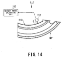
- the radiation therapy apparatus of this embodiment may include a leaf 141", which is provided to the leaf 141 and to which a magnetic tape 210 storing magnetic information is attached (affixed) at regular intervals along its (inner or outer) circumference, and a moving amount detecting unit 211 for detecting plural positions of the leaf 141'' based on the magnetic information to determine a moving amount of the leaf 141''.
- the detected moving amount of the leaf 141'' is fed back to the control device 30.
- the moving amount detecting unit 211 includes a magnetic detection unit (magnetic sensor) 212 and a moving amount calculating unit 213.
- the magnetic sensor 212 detects magnetic information at a fixed point "G" on the moving path of the leaf 141'' so as to obtain magnetic information from the magnetic tape 210 attached to the leaf 141''.
- the magnetic tape 210 has a predetermined distance (several micrometers) from the magnetic detecting unit 212. Thus, there is no influence of change over time such as abrasion. If magnetic information is recorded onto the magnetic tape 210 at regular intervals along the circumference of the leaf 141", a recording pitch corresponds to detection accuracy. Further, the tape can be magnetized on the order of micrometer, so the position of the leaf 141" can be detected.
- the moving amount calculating unit 213 calculates a moving amount of the leaf 141'' based on magnetic information detected with the magnetic sensor 212.
- the magnetic information is output as a pulse signal and thus is subjected to digital processing similar to signal processing of a conventional encoder, so its accuracy and reliability are high.
- a torque wire having a high rotation following capability is used to allow transmission of a torque of the motor as a driving source to a tip end with accuracy while keeping a high flexibility to a bent portion. Accordingly, the torque wire can transmit a torque of the motor to a driving gear with accuracy regardless of orientation and angle of the motor, making it possible to move the leaves concentrically along the arc-shaped path about the radiation source to get close to/away from each other.
- the motor can achieve the very high degree of freedom of arrangement relative to the moving axis of the leaves and can be placed in a dead space in the collimator.
- an internal space of the collimator device 14 can be efficiently utilized, and the number of leaves can be increased without enlarging the collimator device 14.
- the irradiation field "U" can be matched more with a treatment site without reducing the space for the treatment. This enables safer radiotherapy for the object.
- the driving gear 143a of the driving device 143 may be a one-stage gear, so backlash can be easily adjusted and operation accuracy can be improved.
- the moving amount of each leaf can be easily detected using a torque motor with a built-in encoder, making it possible to simplify a complicated mechanism using a number of gears, and a potentiometer or an encoder in combination to control the moving amount.
- a displacement or position detection error due to an influence of backlash or friction between gears can be suppressed.
- a leaf position can be accurately detected and the irradiation field "U" can be accurately matched with an affected area.
Landscapes
- Health & Medical Sciences (AREA)
- Engineering & Computer Science (AREA)
- Physics & Mathematics (AREA)
- Biomedical Technology (AREA)
- Nuclear Medicine, Radiotherapy & Molecular Imaging (AREA)
- High Energy & Nuclear Physics (AREA)
- General Engineering & Computer Science (AREA)
- Pathology (AREA)
- Spectroscopy & Molecular Physics (AREA)
- Radiology & Medical Imaging (AREA)
- Life Sciences & Earth Sciences (AREA)
- Animal Behavior & Ethology (AREA)
- General Health & Medical Sciences (AREA)
- Public Health (AREA)
- Veterinary Medicine (AREA)
- Radiation-Therapy Devices (AREA)
Abstract
Description
- The present invention relates to a radiation therapy apparatus used for a therapy of diseases such as malignant tumors, and particularly to the radiation therapy apparatus including a multi-leaf collimator device which allows an extent of an object that is exposed to radiation (which will be referred to as an "irradiation field" hereafter) to be set with high precision.
- From the perspective of radiation protection, the radiation therapy apparatus includes a collimator device formed of a material the nature of which renders it impermeable to radiation such as tungsten or the like, thereby allowing the exposure to radiation to be limited to a therapy part including a body. Such a collimator device needs to have a function of carefully forming the irradiation field that approximates a shape of the therapy part without a formation of a penumbra. Accordingly, such a collimator device has a; first collimator and a second collimator arranged in the irradiation direction such that they overlap.
- With such an arrangement, the first collimator provided on a near side of a radiation source is configured in a form of a single unit comprising a pair of members disposed such that they face each other across an irradiation axis. Such an arrangement allows that the members drive so as to adjust a distance therebetween. For example, the members drive along an arc-shaped path around the radiation source as a center. On the other hand, the second collimator provided on a far side of the radiation source is configured in the form of a pair of collimator components (blocks) such that the collimator components face each other across the irradiation axis in an orthogonal direction to a moving direction of the first collimator. Each of the collimator components of the second collimator has multiple leaves arranged close to one another, which can be individually moved so as to adjust a distance therebetween along the arc-shaped path around the radiation source as the center.
- The second collimator is called "multi-leaf collimator", which includes, for example, a block pair composed of several ten leaves that are closely gathered side by side. The leaves of the second collimator each have the arc-shaped path and are individually driven movably along the arc-shaped path with a driving device provided to each leaf. Thus, the radiation field of an irregular shape can be formed by combining an operation of moving the first collimator composed of a pair of opposing separate members to get close to/away from each other in an X direction and an operation of individually moving the leaves of the second collimator, which are gathered opposite to each other, so as to get close to/away from each other in a Y direction. Here, the first collimator and the second collimator may be collectively referred to as "multi-leaf collimator".
-
Fig. 15 schematically is oneleaf 41 of the second collimator and a driving device 43 for driving the leaf. Referring toFig. 15 , how to drive theleaf 41 and control its position is described below in brief. - The
leaf 41 ofFig. 15 is formed in a fan shape that converges to a radiation source as seen in a plan view and in a plate-like or wedge shape as seen in a side view. Further, anouter edge 41a of theleaf 41 is curved along the arc-shaped path around the radiation source as the center. A gear tooth is cut in the arc-shaped path plane, that is, the curvedouter edge 41a. Adriving gear 43a is engaged with the tooth of theouter edge 41a. - The
driving gear 43a is fixed to a tip end of ashaft 43b. Theshaft 43b is driven based on a driving force transmitted from amotor 43c as a driving source through a driving force transmitting mechanism such as aworm gear 43d. Apotentiometer 43e and anencoder 43f are arranged to detect a torque, and function as a position detecting device for theleaf 41. Themotor 43c is controlled by an additional control device based on information from thepotentiometer 43e and theencoder 43f, and theleaf 41 is set in a desired position to form a predetermined radiation field (see "Japanese Patent Publication (Laid-open: KOKAI) No. 2002-253686", for example). - In the case of detecting penumbra, leaves of the multi-leaf collimator can be moved closer to/away from each other in a horizontal direction without requiring a complicated structure such as moves the leaves concentrically along the arc-shaped path around the radiation source as the center. One known technique applicable to this case is to drive a threaded shaft connected to each leaf with a motor through a flexible cable (see "Japanese Patent No.
2543373 - As described above, the technique disclosed in "Japanese Patent Publication No.
2002-253686 - However, if the number of leaves is increased, it is necessary to prepare as many driving force transmitting mechanisms such as the motor, the gear and the shaft, as the number of leaves. This causes a problem about how to secure an area enough to arrange as many driving force transmitting mechanisms as the number of leaves in a limited space. Thus, increasing the number of leaves leads to a problem of enlarging the collimator to limit a treatment space of a radiation therapy apparatus itself.
- Further, in the above driving force transmitting mechanism, a torque of the motor is transmitted to each leaf through the gear and the shaft, which imposes a limitation that the motor should be placed in a direction parallel or vertical to a moving axis of each leaf. Thus, the degree of freedom of arrangement is low. As a result, it is difficult to increase the number of leaves. Further, accumulative backlash between engaged gears causes an error in a moving amount of leaves and thus, it is necessary to take a measure for eliminating the backlash.
- On the other hand, the technique disclosed in "Japanese Patent No.
2543373 - The present invention has taken into consideration the above-described problems and it is an object of the present invention to provide the radiation therapy apparatus which a torque wire having a high rotation following allows transmission of a torque of the motor as a driving source to a tip end with accuracy while keeping a high flexibility to a bent portion. Accordingly, the torque wire transmits a torque of the motor to a driving gear with accuracy regardless of orientation and angle of the motor, making it possible to move the leaves concentrically along the arc-shaped path about the radiation source to get close to/away from each other.
- Further, the motor achieves the very high degree of freedom of arrangement relative to the moving axis of the leaves and is placed in a dead space in the collimator. In short, an internal space of the collimator device is efficiently utilized, and the number of leaves is increased without enlarging the collimator device. As a result, the irradiation field is matched more with a treatment site without reducing the space for the treatment, so as to enable safer radiotherapy for the object. Further, the driving gear of the driving device is a one-stage gear, so backlash is easily adjusted and operation accuracy is improved.
- Further, the present invention has taken into consideration the above-described problems and it is an object of the present invention to provide the radiation therapy apparatus which the moving amount of each leaf is easily detected using a torque motor with a built-in encoder, making it to simplify a complicated mechanism using a number of gears, and a potentiometer or an encoder in combination to control the moving amount.
- Further, the present invention has taken into consideration the above-described problems and it is an object of the present invention to provide the radiation therapy apparatus which a displacement or position detection error due to an influence of backlash or friction between gears is suppressed. Hence, a leaf position is accurately detected and the irradiation field is accurately matched with an affected area.
- To solve the above-described problems, the present invention provides the radiation therapy apparatus, comprising: a multi-leaf collimator device having a pair of collimator components which respectively comprise a plurality of leaves arranged close to one another such that the leaves face one another across an irradiation axis, and configured to set a desired irradiation field by individually moving the leaves; a driving gear engaged with a gear tooth of the each leaf, respectively; a torque wire connected to a shaft center of the driving gear, respectively; and a driving unit configured to drive the driving gears through the torque wire.
- In the accompanying drawings:
-
Fig. 1 is an external view which shows a usage condition of the radiation therapy apparatus according to a present embodiment; -
Fig. 2 is a side view, shown a driving direction of the second collimator as a depth direction, which shows the first collimator and the second collimator included the collimator device in the present embodiment; -
Fig. 3 is a side view, shown a first example of a driving direction of the second collimator as an orthogonal direction, which shows the first collimator and the second collimator provided to the collimator device in the present embodiment; -
Fig. 4 is a side view, shown a second example of a driving direction of the second collimator as an orthogonal direction, which shows the first collimator and the second collimator provided to the collimator device in the present embodiment; -
Fig. 5 is a top view which shows a constitution example of the second collimator provided to the collimator device in the present embodiment; -
Fig. 6 is a top view which shows the irradiation field example of the second collimator in the present embodiment; -
Fig. 5 is a top view which shows a constitution example of the second collimator provided to the collimator device in the present embodiment; -
Fig. 6 is a top view which shows the irradiation field example of the second collimator in the present embodiment; -
Fig. 7 is a top view which shows an arrangement example and a formation of the irradiation field by arranging the leaves included the second collimator in the present embodiment; -
Fig. 8 schematically is an arrangement example of the driving device; -
Fig. 9 is a top view of the leaves, which shows an arrangement example of the driving devices; -
Fig. 10 is a side view of the leaves, which shows an arrangement example of the driving devices; -
Fig. 11 schematically is the moving amount detecting unit with respect to the leaf; -
Fig. 12 is a sectional side view of the leaf, which elaborates onFig. 11 ; -
Fig. 13 is a pattern example formed on the leaf; -
Fig. 14 schematically is the moving amount detecting unit with respect to the leaf; and -
Fig. 15 schematically is one leaf of the second collimator and the driving device for driving the leaf. - Detailed description will be made with reference to
Fig. 1 through Fig.14 regarding a radiation therapy apparatus including a multi-leaf collimator device according to an embodiment of the present invention. It should be noted that, in these drawings, the same components are denoted by the same reference numerals. -
Fig. 1 is an external view which shows a usage condition of the radiation therapy apparatus according to a present embodiment. First, description will be made in a schematic fashion with reference toFig. 1 regarding a configuration of the radiation therapy apparatus according to the present embodiment. - In broad terms, the radiation therapy apparatus has an
irradiation device 10 which uses a radiation source to irradiate a predetermined direction, a therapy table 20 on which an object (a person who needs a therapy) P, including a focus, lies and which sets a positioning of a therapy part to be irradiated, and acontrol device 30 which organically controls a components of the radiation therapy apparatus, e.g., theirradiation device 10 and the therapy table 20. - The
irradiation device 10 includes a fixedframe 11 installed on a floor, aturnable frame 12 which is turnably supported by the fixedframe 11, anirradiation head 13 provided to a tip portion extending in the horizontal direction from one end of theturnable frame 12, and acollimator device 14 which is a built-in component of theirradiation head 13. With such an arrangement, theturnable frame 12 can be turned with respect to the fixedframe 11 over approximately 360 degrees around a rotation center axis "H" extending in the horizontal direction. Furthermore, thecollimator device 14 is provided such that it can be turned with respect to theirradiation head 13 around an irradiation axis "I". It should be noted that the intersection of a rotation center axis "H" for theturnable frame 12 and the irradiation axis "I" will be referred to as the "isocenter (IC)" hereafter. With such an arrangement, theturnable frame 12 is configured such that it can be turned according to various kinds of irradiation, examples of which include a rotation irradiation, a pendulum irradiation, an intermittent irradiation, etc. - Furthermore, the therapy table 20 is installed on the floor such that it can be turned over a predetermined angle range in a direction of arrow "G" along an arc with the isocenter IC as a center. Furthermore, a table-
top 22, on which the object P can lie, is provided to a top of the therapy table 20. Here, the table-top plate 22 is supported by anupper portion mechanism 21. Theupper portion mechanism 21 includes a mechanism which allows the table-top 22 to be moved in a longitudinal direction indicated by an arrow "e"' and a lateral direction indicated by an arrow "f". - Furthermore, the
upper portion mechanism 21 is supported by an elevator mechanism 23. The elevator mechanism 23 has a link mechanism, for example. Such an arrangement allows the elevator mechanism 23 itself to be moved in a vertical direction indicated by an arrow "d", thereby allowing theupper portion mechanism 21 and the table-top 22 to be moved in a predetermined range in the vertical direction. Moreover, the elevator mechanism 23 is supported by alower portion mechanism 24. The lower portion mechanism includes a mechanism which allows the elevator mechanism 23 to be turned in the direction indicated by an arrow "F", with the position that is distant from the isocenter IC by a distance "L" as the center. Such an arrangement allows theupper portion mechanism 21 and the table-top 22 to be turned in a predetermined range of angle in the direction indicated by the arrow "F", in addition to the elevator mechanism 23. - It should be noted that such an arrangement allows a medical staff "D" such as a surgeon or the like to operate an operation unit provided to the
control device 30, thereby setting the positioning of the object P and adjusting thecollimator device 14 which defines an irradiation field at a radiation therapy. - It is important for the radiation therapy to irradiate only the therapy part in a concentrated manner without damaging a normal tissue. The
collimator device 14 controls a position to be irradiated, which protects the normal tissue from being exposed to radiation. With such an arrangement, thecollimator device 14 is provided in the form of a built-in component of theirradiation head 13 such that it can be turned around the irradiation axis "I". - Next, description will be made regarding the
collimator device 14 with reference toFig. 2 through Fig.7 .Fig. 2 is a side view, shown a driving direction of asecond collimator 141 as a depth direction, which shows a first collimator 140 and thesecond collimator 141 included thecollimator device 14 in the present embodiment.Fig. 3 is a side view, shown a first example of the driving direction of thesecond collimator 141 as an orthogonal direction, which shows the first collimator 140 and thesecond collimator 141 provided to thecollimator device 14 in the present embodiment.Fig. 4 is a side view, shown a second example of the driving direction of thesecond collimator 141 as an orthogonal direction, which shows the first collimator 140 and thesecond collimator 141 provided to the collimator device in the present embodiment. It should be noted thatFig. 3 andFig. 4 show thecollimator device 14 viewed in an orthogonal direction orthogonal to the direction in which thecollimator 14 shown inFig. 2 is viewed. Furthermore, a housing of thecollimator device 14 is not shown in these drawings.Fig. 5 is a top view which shows a constitution example of the second collimator provided to thecollimator device 14 in the present embodiment. - As shown in
Fig. 2 through Fig. 4 , in general, thecollimator device 14 has two kinds of collimators (a first collimator 140 and a second collimator 141) formed of a heavy metal such as tungsten or the like. These two kinds of collimators are arranged along the irradiation direction from the radiation source "S" such that they overlap. With such an arrangement, each of thecollimators 140 and 141 has a pair of separate components arranged such that they face each other (see the components denoted byreference numerals Fig. 2 andFig. 3 ). Here, such a pair of components forming thecollimator 140 or 141 is differentiated by reference symbols "A" and "B" for convenience of understanding. - With such an arrangement, each of the
first collimator component 140A and thesecond collimator component 140B provided on a near side of the radiation source "S" is configured in the form of a single unit, as clearly shown inFig. 2 . Furthermore, thecollimator components collimator component 140A and an end face of thecollimator component 140B face each other across the irradiation axis "I". Such an arrangement allows thecollimator elements devices collimator components - Also, the
second collimator components Fig. 3 . Furthermore, thecollimator components collimator component 141A and an end face of thecollimator component 141B face each other across the irradiation axis "I". Such an arrangement allows thecollimator elements devices collimator elements collimator components - In another example shown in
Fig. 4 , thesecond collimator components collimator component 141A and the end face of thecollimator component 141B face each other across the irradiation axis "I". Such an arrangement allows thecollimator elements driving devices first collimator elements collimator components - Note that description will be made below regarding an arrangement which allows the first collimator 140 to be driven in the driving direction "X" as described with reference to
Fig. 2 , and which allows thesecond collimator 141 to be driven in the driving direction "Y" as described with reference toFig. 3 . - As shown in
Fig. 2 , thesecond collimator component 141A (141B) has multiple leaves 141A1 - 141An (141B1 - 141Bn) arranged close to one another.Fig. 5 shows the detailed configuration thereof. - That is to say, driving devices 143A1 - 143An (143B1 - 143Bn) are provided to the respective leaves 141A1 - 141An (141B1 - 141Bn) forming the
second collimator component 141A (141B). Such an arrangement allows the leaves 141A1 - 141n (141B1 - 141Bn) to be driven individually in the direction of the arrow "Y" along the arc-shaped path around the radiation source "S" as the center, thereby adjusting the distances therebetween. - Such an arrangement allows the leaves 141A1 - 141An of the
second collimator component 141A and the leaves 141B1 - 141Bn of thesecond collimator component 141B to be moved individually in the "Y" direction so as to adjust the distance therebetween, in addition to allowing thefirst collimator components Fig. 6 , to be formed in a desired shape such that it approximates the shape of the therapy part "T" which is approximately equal to the focus. -
Fig. 7 shows an example of thedriving device 143 such as the driving devices 143A1 - 143An and 1431B1 - 143Bn for driving theleaf 141 such as the leaves 141A1 - 141An and 141B1 - 141Bn. - In the radiation therapy apparatus of this embodiment, the leaves 141A1 - 141An and 141B1 - 141Bn of the
second collimator components leaf 141") are similar to conventional ones. The leaves are formed in a fan shape that converges to the radiation source as seen in a plan view and in a plate-like or wedge shape as seen in a side view. Further, an outer edge of eachleaf 141 is curved along the arc-shaped path around the radiation source "S" as the center. Agear tooth 141a is cut in the arc-shaped path plane, that is, the curved outer edge. Adriving gear 143a of each of the driving devices 143A1 - 143An and 1431B1 - 143Bn (hereinafter simply referred to as "drivingdevice 143") is engaged with thetooth 141a of the outer edge. - The
driving device 143 is composed of thedriving gear 143a, atorque wire 143b, and a torque motor 143c. That is, the driving device is structured such that one end of thetorque wire 143b is connected to the rotation center of thedriving gear 143a engaged with thetooth 141a of the outer edge of theleaf 141, and the other end of thetorque wire 143b is connected to the torque motor 143c. Thus, a torque of the torque motor 143c is transmitted to thedriving gear 143a through thetorque wire 143b to drive theleaf 141. - A feature of the
torque wire 143b is as follows. That is, the wire has a high rotation following capability and thus, can transmit a torque of a driving force such as a motor to a tip end with accuracy. In addition, the wire has flexibility and thus can keep its high performance even at a bent portion. Hence, as shown inFig. 8 , for example, thetorque wire 143b can transmit a torque of the torque motor 143c to thedriving gear 143a with accuracy irrespective of orientation and angle of the torque motor 143c, and can move eachleaf 141 by a desired amount. In other words, theleaf 141 of thesecond collimator components Fig. 8 means that one torque motor 143c is arranged in different directions and at different angles by use of thetorque wire 143b, not that the number of motors is three. - Thus, the
motor 143 achieves the very high degree of freedom of arrangement relative to the moving axis of eachleaf 141 and thus can be placed even in a dead space of a container of thecollimator 14. In short, an internal space of the collimator can be efficiently utilized, and the number of leaves can be increased without enlarging thecollimator 14. As a result, an irradiation field can be more matched with a treatment site without reducing a space for the therapy. This enables safer radiotherapy for the object. Further, thedriving gear 143a of thedriving device 143 may be a one-stage gear, so backlash can be easily adjusted and operation accuracy can be improved. -
Fig. 9 is a top view of the leaves, which shows an arrangement example of the drivingdevices 143.Fig. 10 is a side view of the leaves, which shows an arrangement example of the drivingdevices 143. - In the radiation therapy apparatus of this embodiment, the driving
devices 143 area arranged as shown inFigs. 9 and10 , so themotor 143 achieves the very high degree of freedom of arrangement relative to the moving axis of eachleaf 141 and thus can be placed even in a dead space of the container of thecollimator 14. - If the torque motor 143c is equipped with an encoder, moving amounts of each
leaf 141 can be easily detected, making it possible to simplify a complicated mechanism using a number of gears, and apotentiometer 43e or anencoder 43f in combination as shown inFig. 15 to control the moving amounts. Further, a laser beam disclosed in "Japanese Patent Publication (Laid-open: KOKAI) No.2004-275243 leaf 141 so as to set a position of eachleaf 141. - Moreover, the radiation therapy apparatus of this embodiment as shown in
Figs. 11 to 13 may include a leaf 141' attached to theabove leaf 141 and having apredetermined pattern 200 along its outer circumference, and a movingamount detecting unit 201 for detecting plural positions of the leaf 141' based on thepattern 200 to detect the moving amounts of the leaf 141'. The detected moving amount of the leaf 141' is fed back to thecontrol device 30. In this case, the movingamount detecting unit 201 includes alight irradiation unit 202, an imaging unit (image sensor) 203, and a movingamount calculating unit 204. - The
light irradiating unit 202 secured in a predetermined position is composed of a light emitting diode etc. and applies light to a fixed point "F" on the moving path of theleaf 141 so as to illuminate a part of the pattern formed on the leaf 141'. - The
image sensor 203 secured in a predetermined position is composed of a CCD (charge coupled device) camera etc. and obtains an image in an area including the fixed point "F" to obtain a fixed-point image. - The moving
amount calculating unit 204 calculates the moving amount of the leaf 141' based on plural fixed-point images obtained with theimage sensor 203. - The moving amount of the leaf 141' can be directly detected with the moving
amount detecting unit 201 in a non-contact fashion, so a displacement or position detection error due to an influence of backlash or friction between gears can be suppressed. In the case of directly detecting the moving amount of each leaf using the above methods, any general motor, not a motor with a built-in encoder, can be used. - Referring to
Figs. 11 to 13 , a method of directly detecting the moving amount of the leaf 141' in a non-contact fashion with the movingamount detecting unit 201 is described next.Fig. 11 schematically is the movingamount detecting unit 201 with respect to the leaf 141'.Fig. 12 is a sectional side view of the leaf 141', which elaborates onFig. 11 .Fig. 13 shows a pattern example formed on the leaf 141'. - As shown in
Fig. 11 , thelight irradiating unit 202 illuminates the fixed point "F" on the moving path of theleaf 141, for example, on the moving path of the arc-shaped outer edge of the leaf 141' having a tooth 141'a cut therein. Theimage sensor 203 obtains the image in an area including the fixed point on the moving path of the arc-shaped to obtain a fixed-point image. - As shown in
Fig. 12 , the arc-shaped outer edge of the leaf 141' is divided along a moving direction of the leaf 141' into a portion for forming a tooth 141'a and a portion 141'b for forming the pattern 200 (seeFig. 13 ), not forming the tooth 141'a. In other words, the tooth 141'a and thepattern 200 are formed in line along a thickness direction of the leaf 141'. Then, the leaf 141' is engaged with thedriving gear 143a, and thelight irradiating unit 202 applies light onto the moving path of the portion 141'b of the arc-shaped outer edge, in which thepattern 200 is formed. - The
pattern 200 is engraved along the arc-shaped outer edge of the leaf 141'. As shown inFig. 13 by way of example, thepattern 200 is formed by engraving the outer edge at plural positions in a line at regular intervals. The pattern extends over a range similar to a movable range of the leaf 141'. The pattern includesunique patterns 200a in predetermined positions. Theunique patterns 200a means characteristics patterns different from patterns of the other region of the pattern (inclusive of unpatterned region). - The
pattern 200 includes consecutive blocks obtained by dividing, for example, an area measuring about 0.5 [mm] x 0.5 [mm] into 16 blocks in a lattice form with theunique pattern 200a being formed at one corner of the lattice area. Theunique patterns 200a are colored in black inFig. 13 but may be uniformly ground more than the other blocks or have coarse grooves formed therein instead of being colored. - If the
light irradiating unit 202 secured in a predetermined position applies light, the light illuminates a part of thepattern 200 as shown inFig. 13 . The irradiation direction of thelight irradiating unit 202 is fixed. And the fixed point "F" is set in an absolute position not influenced and has a predetermined area. Further, thelight irradiating unit 202 sets the fixed point "F" in the arc-shaped outer edge of the leaf 141' and sets an irradiation range including a part of the area including thepattern 200. - On the other hand, the
image sensor 203 is set to image of an area including the fixed point "F" on the pattern 200' at regular intervals along the arc-shaped outer edge of leaf 141'-That is, theimage sensor 203 receives light reflected by the fixed point "F" with time and obtains a fixed-point image at regular intervals. The fixed-point image includes a part of thepattern 200 engraved in the leaf 141'. Thepattern 200 includes theunique pattern 200a, so the movingamount calculating unit 204 specifies a position of theunique pattern 200 obtained with theimage sensor 203 to calculate a moving amount of the leaf 141' based on its time lag. - That is, the moving
amount calculating unit 204 analyzes plural fixed-point images obtained on the time-series basis in accordance with the moving of the leaf 141' to thereby obtain a moving amount of the leaf 141'. If the leaf 141' moves, thepattern 200 engraved in the leaf 141' is moved together with thepattern 200. Thus, a position of the fixed point "F" is relatively changed on thepattern 200 including theunique pattern 200a in the plural fixed-point images obtained on the time-series basis. Hence, the detectingunit 201 can detect a moving amount of the leaf 141' by the movingamount calculating unit 204 specifying a position of the fixed point "F" relative to the pattern on the plural fixed-point images obtained on the time-series basis and determining displacement of the position. - The fixed-point image desirably includes a part or all of the
unique pattern 200 regardless of the moving amount of the leaf 141'. Accordingly, thepattern 200 formed in the leaf 141' is desirably minimized in size. The reason thepattern 200 is divided into blocks each measuring about 0.5 mm per side with thepattern 200a set to one block is that thepattern 200a is set smaller than an area obtained with theimage sensor 203. - As shown in
Fig. 14 , the radiation therapy apparatus of this embodiment may include aleaf 141", which is provided to theleaf 141 and to which amagnetic tape 210 storing magnetic information is attached (affixed) at regular intervals along its (inner or outer) circumference, and a movingamount detecting unit 211 for detecting plural positions of the leaf 141'' based on the magnetic information to determine a moving amount of the leaf 141''. The detected moving amount of the leaf 141'' is fed back to thecontrol device 30. In this case, the movingamount detecting unit 211 includes a magnetic detection unit (magnetic sensor) 212 and a movingamount calculating unit 213. - The
magnetic sensor 212 detects magnetic information at a fixed point "G" on the moving path of the leaf 141'' so as to obtain magnetic information from themagnetic tape 210 attached to the leaf 141''. Here, themagnetic tape 210 has a predetermined distance (several micrometers) from the magnetic detectingunit 212. Thus, there is no influence of change over time such as abrasion. If magnetic information is recorded onto themagnetic tape 210 at regular intervals along the circumference of theleaf 141", a recording pitch corresponds to detection accuracy. Further, the tape can be magnetized on the order of micrometer, so the position of theleaf 141" can be detected. - The moving
amount calculating unit 213 calculates a moving amount of the leaf 141'' based on magnetic information detected with themagnetic sensor 212. The magnetic information is output as a pulse signal and thus is subjected to digital processing similar to signal processing of a conventional encoder, so its accuracy and reliability are high. - According to the radiation therapy apparatus of this embodiment, a torque wire having a high rotation following capability is used to allow transmission of a torque of the motor as a driving source to a tip end with accuracy while keeping a high flexibility to a bent portion. Accordingly, the torque wire can transmit a torque of the motor to a driving gear with accuracy regardless of orientation and angle of the motor, making it possible to move the leaves concentrically along the arc-shaped path about the radiation source to get close to/away from each other.
- Therefore, the motor can achieve the very high degree of freedom of arrangement relative to the moving axis of the leaves and can be placed in a dead space in the collimator. In short, an internal space of the
collimator device 14 can be efficiently utilized, and the number of leaves can be increased without enlarging thecollimator device 14. As a result, the irradiation field "U" can be matched more with a treatment site without reducing the space for the treatment. This enables safer radiotherapy for the object. Further, thedriving gear 143a of thedriving device 143 may be a one-stage gear, so backlash can be easily adjusted and operation accuracy can be improved. - Further, according to the radiation therapy apparatus of this embodiment, the moving amount of each leaf can be easily detected using a torque motor with a built-in encoder, making it possible to simplify a complicated mechanism using a number of gears, and a potentiometer or an encoder in combination to control the moving amount.
- Further, according to the radiation therapy apparatus of this embodiment, a displacement or position detection error due to an influence of backlash or friction between gears can be suppressed. Hence, a leaf position can be accurately detected and the irradiation field "U" can be accurately matched with an affected area.
- It is explicitly stated that all features disclosed in the description and/or the claims are intended to be disclosed separately and independently from each other for the purpose of original disclosure as well as for the purpose of restricting the claimed invention independent of the composition of the features in the embodiments and/or the claims. It is explicitly stated that all value ranges or indications of groups of entities disclose every possible intermediate value or intermediate entity for the purpose of original disclosure as well as for the purpose of restricting the claimed invention, in particular as limits of value ranges.
Claims (8)
- A radiation therapy apparatus comprising:a multi-leaf collimator device (14) having a pair of collimator components (140A, 140B; 141A, 141B) which respectively comprise a plurality of leaves (141A1-141An, 141B1-141Bn) arranged close to one another such that the leaves (141A1-141An, 141B1-141Bn) face one another across an irradiation axis (I), and configured to set a desired irradiation field by individually moving the leaves (141A1-141An, 141B1-141Bn);a driving gear (143a) engaged with a gear tooth (141a) of each leaf (141A1-141An, 141B1-141Bn), respectively;a torque wire (143b) connected to a shaft center of the driving gear (143a), respectively; anda driving unit configured to drive the driving gears (143a) through the torque wire (143b).
- The radiation therapy apparatus according to Claim 1, wherein the driving means is a torque motor (143c) with a built-in encoder.
- The radiation therapy apparatus according to Claim 1 or 2, further comprising:a plurality of patterned leaves obtained by forming a predetermined patter (200) in the leaves in a moving direction along its moving path; anda moving amount detecting unit (201) configured to detect a moving amount of each patterned leaf respectively, by obtaining a plurality of positions of each patterned leaf based on the pattern (200).
- The radiation therapy apparatus according to Claim 3, wherein the moving amount detecting unit (201) includes:a light irradiating unit (202) configured to apply light to a fixed point on the moving path of the patterned leaves so as to illuminate a part of the pattern (200);an imaging unit (203) configured to obtain an image in an area including the fixed point on the pattern (200) to obtain a fixed-point image; anda moving amount calculating unit (204) configured to calculate the moving amount of each patterned leaf based on the fixed-point image obtained with the imaging unit (203).
- The radiation therapy apparatus according to Claim 3 or 4, wherein the pattern (200) is formed on an outer side of each leaf, respectively.
- The radiation therapy apparatus according to Claim 1 or 2, further comprising:a plurality of magnetic tape-attached leaves obtained by attaching a magnetic tape (210) storing magnetic information to the leaves at regular intervals along the moving direction on its moving path; anda moving amount detecting unit (211) configured to detect a moving amount of each magnetic tape-attached leaf respectively, by obtaining a plurality of positions of each magnetic tape-attached leaf based on the magnetic information.
- The radiation therapy apparatus according to any of Claims 1 to 6, wherein the leaves have an arc-shaped moving path.
- The radiation therapy apparatus according to any of Claims 1 to 6, wherein the leaves have a linear moving path.
Applications Claiming Priority (1)
| Application Number | Priority Date | Filing Date | Title |
|---|---|---|---|
| JP2007044165 | 2007-02-23 |
Publications (2)
| Publication Number | Publication Date |
|---|---|
| EP1961446A1 true EP1961446A1 (en) | 2008-08-27 |
| EP1961446B1 EP1961446B1 (en) | 2009-12-30 |
Family
ID=39415377
Family Applications (1)
| Application Number | Title | Priority Date | Filing Date |
|---|---|---|---|
| EP08003140A Ceased EP1961446B1 (en) | 2007-02-23 | 2008-02-20 | Radiation therapy apparatus |
Country Status (4)
| Country | Link |
|---|---|
| US (1) | US7672435B2 (en) |
| EP (1) | EP1961446B1 (en) |
| JP (1) | JP2008229324A (en) |
| DE (1) | DE602008000456D1 (en) |
Cited By (6)
| Publication number | Priority date | Publication date | Assignee | Title |
|---|---|---|---|---|
| WO2011107111A1 (en) * | 2010-03-02 | 2011-09-09 | Elekta Ab (Publ) | Position detection for multi-leaf collimators |
| WO2012089535A1 (en) * | 2010-12-29 | 2012-07-05 | Deutsches Krebsforschungszentrum | Multi-leaf collimator with leaf drive |
| EP2500909A1 (en) * | 2011-03-16 | 2012-09-19 | Deutsches Krebsforschungszentrum Stiftung des Öffentlichen Rechts | Position sensoring method and system for a multi-leaf collimator |
| US8537373B2 (en) | 2010-03-02 | 2013-09-17 | Elekta Ab (Publ) | Position detection |
| EP2572755A4 (en) * | 2010-08-17 | 2014-01-01 | Mitsubishi Electric Corp | MULTILAME COLLIMATOR, PARTICLE BEAM THERAPY DEVICE, AND THERAPY PLANNING DEVICE |
| US11600400B2 (en) * | 2020-01-21 | 2023-03-07 | Shanghai United Imaging Healthcare Co., Ltd. | Driving mechanism |
Families Citing this family (21)
| Publication number | Priority date | Publication date | Assignee | Title |
|---|---|---|---|---|
| JP2009072443A (en) * | 2007-09-21 | 2009-04-09 | Toshiba Corp | Multi-leaf collimator and radiotherapy device |
| US8625738B2 (en) * | 2008-09-22 | 2014-01-07 | Telesecurity Sciences, Inc. | Radiation therapy and scanning system |
| US8530849B2 (en) * | 2008-09-22 | 2013-09-10 | Telesecurity Sciences, Inc. | Electron beam scanner |
| CN102512765A (en) * | 2008-12-24 | 2012-06-27 | 同方威视技术股份有限公司 | Multi-blade collimator for medical radiotherapy equipment |
| US8487286B2 (en) * | 2009-08-25 | 2013-07-16 | Kabushiki Kaisha Toshiba | Radiation therapy equipment |
| CN105056405B (en) * | 2010-08-17 | 2018-01-19 | 三菱电机株式会社 | Particle-beam therapeutic apparatus |
| EP2621342B1 (en) * | 2010-09-30 | 2017-08-09 | Koninklijke Philips N.V. | Dynamic filter for computed tomography (ct) |
| CN102543242A (en) * | 2010-12-09 | 2012-07-04 | Ge医疗系统环球技术有限公司 | Linkage mechanism, beam limiter and X-ray machine |
| JP5596586B2 (en) * | 2011-02-03 | 2014-09-24 | 三菱電機株式会社 | Multi-leaf collimator, particle beam therapy apparatus, and therapy planning apparatus |
| US10675487B2 (en) | 2013-12-20 | 2020-06-09 | Mevion Medical Systems, Inc. | Energy degrader enabling high-speed energy switching |
| US9962560B2 (en) | 2013-12-20 | 2018-05-08 | Mevion Medical Systems, Inc. | Collimator and energy degrader |
| JP5972322B2 (en) * | 2014-08-07 | 2016-08-17 | 三菱電機株式会社 | Particle beam therapy system |
| US10786689B2 (en) * | 2015-11-10 | 2020-09-29 | Mevion Medical Systems, Inc. | Adaptive aperture |
| CN105749432A (en) * | 2016-01-13 | 2016-07-13 | 深圳市埃贝克科技有限公司 | Multi-leaf grating blade with magnetism |
| WO2018009779A1 (en) | 2016-07-08 | 2018-01-11 | Mevion Medical Systems, Inc. | Treatment planning |
| US11103730B2 (en) | 2017-02-23 | 2021-08-31 | Mevion Medical Systems, Inc. | Automated treatment in particle therapy |
| WO2019006253A1 (en) | 2017-06-30 | 2019-01-03 | Mevion Medical Systems, Inc. | Configurable collimator controlled using linear motors |
| WO2021007707A1 (en) | 2019-07-12 | 2021-01-21 | Shanghai United Imaging Healthcare Co., Ltd. | Multi-leaf collimator |
| US12485294B2 (en) * | 2020-06-02 | 2025-12-02 | Elekta Limited | Beam shaping apparatus |
| US11344749B2 (en) * | 2020-10-16 | 2022-05-31 | Varian Medical Systems, Inc. | Magnetoresistive linear position detection in a radiation therapy system |
| KR102752687B1 (en) * | 2023-06-30 | 2025-01-10 | 오스템임플란트 주식회사 | X-ray imaging apparatus |
Citations (12)
| Publication number | Priority date | Publication date | Assignee | Title |
|---|---|---|---|---|
| GB450874A (en) * | 1935-01-29 | 1936-07-27 | Frank Edmund Bancroft | Improvements in and relating to shutters in or for x-ray tube installations |
| DE970771C (en) * | 1942-03-21 | 1958-12-11 | Mueller C H F Ag | Device for stopping X-rays |
| US5067144A (en) * | 1990-05-18 | 1991-11-19 | Hologic, Inc. | Equalized radiography using special modulator pins |
| JP2543373B2 (en) | 1986-09-10 | 1996-10-16 | バリアン・アソシエイツ・インコーポレイテッド | Multi-leaf collimator and compensator for radiotherapy machines |
| JP2593373B2 (en) | 1991-09-18 | 1997-03-26 | 本田技研工業株式会社 | Accelerometer mounting bracket |
| DE19536804A1 (en) * | 1995-10-02 | 1997-04-03 | Deutsches Krebsforsch | Contour collimator for radiation therapy |
| JP2002253686A (en) | 2000-12-26 | 2002-09-10 | Toshiba Corp | Radiation therapy device and backlash removal device |
| US20020126799A1 (en) * | 2000-12-19 | 2002-09-12 | Jean-Pierre Saladin | Adjustable collimator and method |
| JP2003210594A (en) * | 2002-01-21 | 2003-07-29 | Toshiba Corp | Leaf drive method and drive device, and radiation therapy device |
| JP2004275243A (en) | 2003-03-13 | 2004-10-07 | Toshiba Corp | Multi-segment diaphragm device |
| EP1712254A1 (en) * | 2004-01-13 | 2006-10-18 | Right Mfg. Co., Ltd. | Device for limiting field on which raddiation is irradiated |
| JP2007037828A (en) * | 2005-08-04 | 2007-02-15 | Toshiba Corp | Multi-leaf collimator and radiotherapy apparatus provided with the same |
Family Cites Families (6)
| Publication number | Priority date | Publication date | Assignee | Title |
|---|---|---|---|---|
| JPH0165045U (en) * | 1987-10-20 | 1989-04-26 | ||
| JP3237257B2 (en) * | 1993-01-19 | 2001-12-10 | 富士電機株式会社 | Automatic door position detection device |
| JP2004051244A (en) * | 2002-07-16 | 2004-02-19 | Sumitomo Heavy Ind Ltd | Method and device for conveying and positioning tape tab |
| US20050047856A1 (en) * | 2003-08-29 | 2005-03-03 | Allswede Stephen W. | Cable drive system |
| US7167542B2 (en) * | 2004-09-27 | 2007-01-23 | Siemens Medical Solutions Usa, Inc. | Motor arrangement and methods for a multi-leaf collimator |
| JP4703421B2 (en) | 2006-02-02 | 2011-06-15 | 株式会社東芝 | Multi-leaf collimator and radiotherapy apparatus provided with the same |
-
2008
- 2008-02-14 JP JP2008032993A patent/JP2008229324A/en active Pending
- 2008-02-20 DE DE602008000456T patent/DE602008000456D1/en active Active
- 2008-02-20 EP EP08003140A patent/EP1961446B1/en not_active Ceased
- 2008-02-21 US US12/035,143 patent/US7672435B2/en not_active Expired - Fee Related
Patent Citations (12)
| Publication number | Priority date | Publication date | Assignee | Title |
|---|---|---|---|---|
| GB450874A (en) * | 1935-01-29 | 1936-07-27 | Frank Edmund Bancroft | Improvements in and relating to shutters in or for x-ray tube installations |
| DE970771C (en) * | 1942-03-21 | 1958-12-11 | Mueller C H F Ag | Device for stopping X-rays |
| JP2543373B2 (en) | 1986-09-10 | 1996-10-16 | バリアン・アソシエイツ・インコーポレイテッド | Multi-leaf collimator and compensator for radiotherapy machines |
| US5067144A (en) * | 1990-05-18 | 1991-11-19 | Hologic, Inc. | Equalized radiography using special modulator pins |
| JP2593373B2 (en) | 1991-09-18 | 1997-03-26 | 本田技研工業株式会社 | Accelerometer mounting bracket |
| DE19536804A1 (en) * | 1995-10-02 | 1997-04-03 | Deutsches Krebsforsch | Contour collimator for radiation therapy |
| US20020126799A1 (en) * | 2000-12-19 | 2002-09-12 | Jean-Pierre Saladin | Adjustable collimator and method |
| JP2002253686A (en) | 2000-12-26 | 2002-09-10 | Toshiba Corp | Radiation therapy device and backlash removal device |
| JP2003210594A (en) * | 2002-01-21 | 2003-07-29 | Toshiba Corp | Leaf drive method and drive device, and radiation therapy device |
| JP2004275243A (en) | 2003-03-13 | 2004-10-07 | Toshiba Corp | Multi-segment diaphragm device |
| EP1712254A1 (en) * | 2004-01-13 | 2006-10-18 | Right Mfg. Co., Ltd. | Device for limiting field on which raddiation is irradiated |
| JP2007037828A (en) * | 2005-08-04 | 2007-02-15 | Toshiba Corp | Multi-leaf collimator and radiotherapy apparatus provided with the same |
Cited By (7)
| Publication number | Priority date | Publication date | Assignee | Title |
|---|---|---|---|---|
| WO2011107111A1 (en) * | 2010-03-02 | 2011-09-09 | Elekta Ab (Publ) | Position detection for multi-leaf collimators |
| US8537373B2 (en) | 2010-03-02 | 2013-09-17 | Elekta Ab (Publ) | Position detection |
| EP2572755A4 (en) * | 2010-08-17 | 2014-01-01 | Mitsubishi Electric Corp | MULTILAME COLLIMATOR, PARTICLE BEAM THERAPY DEVICE, AND THERAPY PLANNING DEVICE |
| WO2012089535A1 (en) * | 2010-12-29 | 2012-07-05 | Deutsches Krebsforschungszentrum | Multi-leaf collimator with leaf drive |
| EP2500909A1 (en) * | 2011-03-16 | 2012-09-19 | Deutsches Krebsforschungszentrum Stiftung des Öffentlichen Rechts | Position sensoring method and system for a multi-leaf collimator |
| WO2012123093A1 (en) * | 2011-03-16 | 2012-09-20 | Deutsches Krebsforschungszentrum Stiftung des öffentlichen Rechts | Position sensoring method and system for a multi-leaf collimator |
| US11600400B2 (en) * | 2020-01-21 | 2023-03-07 | Shanghai United Imaging Healthcare Co., Ltd. | Driving mechanism |
Also Published As
| Publication number | Publication date |
|---|---|
| EP1961446B1 (en) | 2009-12-30 |
| DE602008000456D1 (en) | 2010-02-11 |
| JP2008229324A (en) | 2008-10-02 |
| US20080205599A1 (en) | 2008-08-28 |
| US7672435B2 (en) | 2010-03-02 |
Similar Documents
| Publication | Publication Date | Title |
|---|---|---|
| EP1961446B1 (en) | Radiation therapy apparatus | |
| KR102163767B1 (en) | X-ray collimator and X-ray imaging apparatus using the same | |
| US10646189B2 (en) | Controlling motion position of multi-leaf collimator | |
| KR100960823B1 (en) | Charged particle beam irradiation device | |
| JP4184839B2 (en) | Multi-segment diaphragm device | |
| EP3603523B1 (en) | Apparatus for digital imaging in the head region of a patient | |
| KR20090093654A (en) | Collimator device for radiotherapy and curing device using thereof | |
| EP3097854A1 (en) | Ct photographic device | |
| US20170188981A1 (en) | X-ray imaging apparatus | |
| JP2006051199A (en) | Radiotherapy device, method for tracking affected area of radiotherapy device, and method for improving image quality of imaging image | |
| CA2801817A1 (en) | Adjustable dynamic x-ray filter | |
| JP2010104452A (en) | Multileaf collimator and radiotherapy apparatus | |
| KR101473531B1 (en) | Adaptive Sensor Unit, X-ray Imaging Appratus and X-ray Imaging Method | |
| US8487286B2 (en) | Radiation therapy equipment | |
| KR20100055973A (en) | X-ray apparatus having structure for setting source to image distance | |
| CN215937599U (en) | Puncture laser guiding device and system thereof | |
| JP5078972B2 (en) | Radiotherapy apparatus control method and radiotherapy apparatus control apparatus | |
| KR100740339B1 (en) | Long-term motion reproduction | |
| CN113712647A (en) | Puncture laser guiding device and system thereof | |
| KR20160072904A (en) | X-ray photographing apparatus | |
| WO2007044469A2 (en) | A method and apparatus to direct radiation treatment to a specific region of the brain | |
| JP4436342B2 (en) | Radiotherapy apparatus control apparatus and radiation irradiation method | |
| EP2888743B1 (en) | X-ray apparatus | |
| US20220167933A1 (en) | X-ray imaging apparatus | |
| CN114305479A (en) | Positioning collimator of digital X-ray imaging system |
Legal Events
| Date | Code | Title | Description |
|---|---|---|---|
| PUAI | Public reference made under article 153(3) epc to a published international application that has entered the european phase |
Free format text: ORIGINAL CODE: 0009012 |
|
| 17P | Request for examination filed |
Effective date: 20080220 |
|
| AK | Designated contracting states |
Kind code of ref document: A1 Designated state(s): AT BE BG CH CY CZ DE DK EE ES FI FR GB GR HR HU IE IS IT LI LT LU LV MC MT NL NO PL PT RO SE SI SK TR |
|
| AX | Request for extension of the european patent |
Extension state: AL BA MK RS |
|
| AKX | Designation fees paid |
Designated state(s): DE |
|
| GRAP | Despatch of communication of intention to grant a patent |
Free format text: ORIGINAL CODE: EPIDOSNIGR1 |
|
| GRAS | Grant fee paid |
Free format text: ORIGINAL CODE: EPIDOSNIGR3 |
|
| GRAA | (expected) grant |
Free format text: ORIGINAL CODE: 0009210 |
|
| AK | Designated contracting states |
Kind code of ref document: B1 Designated state(s): DE |
|
| REF | Corresponds to: |
Ref document number: 602008000456 Country of ref document: DE Date of ref document: 20100211 Kind code of ref document: P |
|
| PLBE | No opposition filed within time limit |
Free format text: ORIGINAL CODE: 0009261 |
|
| STAA | Information on the status of an ep patent application or granted ep patent |
Free format text: STATUS: NO OPPOSITION FILED WITHIN TIME LIMIT |
|
| 26N | No opposition filed |
Effective date: 20101001 |
|
| PGFP | Annual fee paid to national office [announced via postgrant information from national office to epo] |
Ref country code: DE Payment date: 20160216 Year of fee payment: 9 |
|
| REG | Reference to a national code |
Ref country code: DE Ref legal event code: R081 Ref document number: 602008000456 Country of ref document: DE Owner name: TOSHIBA MEDICAL SYSTEMS CORPORATION, OTAWARA-S, JP Free format text: FORMER OWNERS: KABUSHIKI KAISHA TOSHIBA, TOKIO/TOKYO, JP; TOSHIBA MEDICAL SYSTEMS CORPORATION, OTAWARA-SHI, TOCHIGI-KEN, JP Ref country code: DE Ref legal event code: R082 Ref document number: 602008000456 Country of ref document: DE Representative=s name: KRAMER BARSKE SCHMIDTCHEN PATENTANWAELTE PARTG, DE |
|
| REG | Reference to a national code |
Ref country code: DE Ref legal event code: R119 Ref document number: 602008000456 Country of ref document: DE |
|
| PG25 | Lapsed in a contracting state [announced via postgrant information from national office to epo] |
Ref country code: DE Free format text: LAPSE BECAUSE OF NON-PAYMENT OF DUE FEES Effective date: 20170901 |