EP1961359A1 - Wiping cover for a cleaning device - Google Patents
Wiping cover for a cleaning device Download PDFInfo
- Publication number
- EP1961359A1 EP1961359A1 EP07003644A EP07003644A EP1961359A1 EP 1961359 A1 EP1961359 A1 EP 1961359A1 EP 07003644 A EP07003644 A EP 07003644A EP 07003644 A EP07003644 A EP 07003644A EP 1961359 A1 EP1961359 A1 EP 1961359A1
- Authority
- EP
- European Patent Office
- Prior art keywords
- wipe
- wiping cover
- layers
- wiping
- active material
- Prior art date
- Legal status (The legal status is an assumption and is not a legal conclusion. Google has not performed a legal analysis and makes no representation as to the accuracy of the status listed.)
- Granted
Links
Images


Classifications
-
- A—HUMAN NECESSITIES
- A47—FURNITURE; DOMESTIC ARTICLES OR APPLIANCES; COFFEE MILLS; SPICE MILLS; SUCTION CLEANERS IN GENERAL
- A47L—DOMESTIC WASHING OR CLEANING; SUCTION CLEANERS IN GENERAL
- A47L13/00—Implements for cleaning floors, carpets, furniture, walls, or wall coverings
- A47L13/10—Scrubbing; Scouring; Cleaning; Polishing
- A47L13/20—Mops
Definitions
- the invention relates to a wiping cover for a cleaning device, comprising at least two layers which are arranged relative to each other such that a pocket to accommodate a part of a cleaning device is obtained, wherein a wipe-active material is attached to at least one layer.
- Such wiping covers are mounted on wiping plates of flat wipe cloths and serve for the moist cleaning of floor coverings.
- the layers of the wiping covers mostly consist of a textile fabric and the wipe-active materials are for example strands or flat coverings of microfibres.
- the wipe-active materials accommodate the cleaning liquid and the dirt particles during cleaning.
- To manufacture a wiping cover the layers are joined with one another through sewing. The strands are frequently attached on the layers also through a seam. Although this type of joining is particularly robust and durable it however requires great manual effort so that the manufacture of a wiping cover is time-intensive and expensive.
- the invention is based on the object of developing a wiping cover which can be manufactured easily and cost-effectively.
- the layers and/or the wipe-active material are adhesively bonded with one another.
- Fabric-positive joins are particularly easy to manufacture.
- the process steps for being able to manufacture a fabric-positive joint can additionally be automated so that the manufacture of a wiping cover is simpler and saves,more time.
- a robust joint which, like the conventional wiping covers, can for example be subjected to a multiplicity of washing operations.
- Fabric-positive joints with and without additive, in this case more preferably adhesives, are conceivable.
- the fabric-positive joint is preferably carried out through ultrasonic welding.
- Ultrasonic welding is a joining method which requires no additive. At the same time, process control is possible wherein the cutting to size of the layers and their material-positive joining takes place in one operation, thus saving time. To this end, the layers are punched from web roll material and simultaneously welded together at the edges.
- the layers can consist of a plastic fabric or of a fabric with a plastic component, for example a mixed plastic-cotton fabric.
- Plastic fabrics or fabrics with a plastic component are particularly robust and tear-resistant and additionally highly suitable for ultrasonic welding.
- Conceivable plastics are meltable plastics and, here, more preferably thermoplastics. These are highly suitable for ultrasonic welding.
- the layers can consist of polyethylene, polypropylene or polyamide or of compounds thereof.
- plastics are economical and length material of these plastics is particularly suitable for ultrasonic welding.
- Highly preferable are plastics which are non-hydrolytically degradable. These are for example polyolefins, more preferably polypropylene and aramid fibres.
- wiping covers of such plastics are less sensitive and a longer utilisation duration is obtained even with frequent washing operations.
- the utilisation duration of wiping covers, in this case, is mostly determined through the number of washing and bleaching operations.
- Plastics of polycondensates for example polyethylene, have a tendency to hydrolysis upon frequent contact with suds, as a result of which the stability of the plastics drops and the wiping covers manufactured from it become unusable.
- Polyolefins and aramid fibres however are not subject to hydrolysis.
- the layers can entirely consist of plastics which are not subject to hydrolysis or only certain components of the layers, more preferably such which are subject to particular loads. These are more preferably the edges of the layers, joining points, seams and such like. It is further possible through insert elements not subject to hydrolysis to reinforce the particularly loaded components.
- the wipe-active material can be formed of strands.
- Strands have a high water absorption capability so that wiping covers equipped with strands achieve a high unit surface performance.
- strands can be provided economically.
- the strands can be combined into ribbons.
- Such ribbons can be produced in an automated way as a primary product.
- the attachment of the strands on the layers is simplified.
- the ribbons are cut to size, arranged on the layers and adhesively bonded with the latter.
- the joint can more preferably be performed also through ultrasonic welding. Ribbons are highly suitable for this purpose since the individual strands in this case are already fixed in the ribbons and it is sufficient to fix the ribbons by sections.
- the attachment can also be performed line-like.
- the wipe-active material can consist of a flat product.
- a particularly large wipe-active surface is obtained through the flat product.
- the flat product can be arranged fabric-positively on one or both layers.
- the layers merely form a carrier.
- the wipe-active material itself forms a layer. This results in material saving since the wipe-active material in this case forms the carrier at the same time.
- One or both layers can be formed through the flat wipe-active material.
- the flat wipe-active materials are material-positively joined at the edges.
- the wipe-active material can comprise microfibres. Microfibres are characterized by particularly good dirt absorption capacity.
- the wiping cover for a cleaning device comprises at least one layer on which, at least on one side, a wipe-active material is attached and the edges of the layer are sealed at least by sections.
- This sealing is carried out more preferably through fabric-positive joining of the strands protruding from the edges.
- the edge can be open or a seam can be formed. This seam can also be formed through fabric-positive joining. As a result, a further expensive sewing process is omitted.
- the sealing of the edges is preferably performed through ultrasonic treatment. Here, several process operations can be combined. Cutting to size of the layers and simultaneous sealing of the edges is carried out through ultrasonic cutting or ultrasonic punching.
- At least one layer can have a recess, wherein the edges of the recess are sealed through ultrasonic welding, Popularly, such recesses are punched out and subsequently sewn in with a reinforcing ribbon to prevent fraying of the edges. During ultrasonic welding the edges are slightly melted and the fibres are bonded together at the edges so that fraying is not possible. Sewing on of a special reinforcing ribbon is obsolete. Through ultrasonic welding it is also possible to attach other parts such as finger loops or labels to the wiping cover,
- Figure 1 shows a wiping cover 1 for a cleaning device 2 which in this development is designed as a flat wipe cloth.
- the cleaning device 2 comprises a wiping plate 12 which is linked to a stem 13.
- the wiping cover 1 according to the invention is mounted onto the wiping plate 12.
- FIG 2 shows in detail a wiping cover 1 for the cleaning device 2 shown in Figure 1 .
- the wiping cover 1 consists of two layers 3, 4. These are arranged relative to each other such that a pocket 5 to accommodate a part of the cleaning device 2, in this case the wiping plate 12, is obtained.
- the layers 3, 4 are manufactured of a one-part flat plastic fabric design consisting of polyamide.
- the plastic fabric cut to size is folded along the subsequent front edge 14 and adhesively bonded along the edges 15 through ultrasonic welding such that an opening to accommodate the wiping plate 12 remains in the wiping cover 1.
- the welding is performed such that an interrupted line 16 is obtained.
- the weld seam can also be performed continuously or spot-type.
- a wipe-active material 6 is attached on both layers 3, 4 which consists of strands 7.
- the strands 7 are joined together in ribbons 8.
- the ribbons 8 and thus the strands 7 are fabric-positively attached to the layers 3,4 through ultrasonic welding. Fixing takes place through several spot-welds 17 arranged at a distance relative to one another to obtain the greatest possible flexibility of the wiping cover 1.
- the wiping cover 1 additionally has a finger loop 17, which is also attached to the wiping cover 1 through ultrasonic welding.
- Both layers 3, 4 have a recess 9 to achieve greater freedom of movement for the stem 13. These recesses 9 are punched out by means of an ultrasonic tool and simultaneously sealed at their edges 10. Upon sealing, the fibres forming the boundaries of the edges 10 are melted and joined with one another.
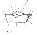
- FIG 3 shows a wiping cover 1 for the cleaning device 2 shown in Figure 1 in detail.
- the wipe-active material 6 consists of a flat textile product 8, containing microfibres.
- the product 8 is arranged on a layer 4 and adhesively bonded with the layer 4 at the edges 15 through ultrasonic welding.
- the product 8 is arranged on both layers 3, 4 or it forms one or both layers 3, 4.
- the invention also comprises wiping covers 1 for pocket mops.
- Such wiping covers 1 have a basic body with a cleaning side on which the strands 7 or the fabric 8 are arranged. The attachment is carried out as described before. On the other side of the basic body on the narrow sides, pockets to accommodate the mop wings of the pocket mop are located. These pockets according to the invention can also be fabric-positively attached to the basic body through ultrasonic welding.
Landscapes
- Cleaning Implements For Floors, Carpets, Furniture, Walls, And The Like (AREA)
- Laminated Bodies (AREA)
Abstract
Description
- The invention relates to a wiping cover for a cleaning device, comprising at least two layers which are arranged relative to each other such that a pocket to accommodate a part of a cleaning device is obtained, wherein a wipe-active material is attached to at least one layer.
- Such wiping covers are mounted on wiping plates of flat wipe cloths and serve for the moist cleaning of floor coverings. The layers of the wiping covers mostly consist of a textile fabric and the wipe-active materials are for example strands or flat coverings of microfibres. The wipe-active materials accommodate the cleaning liquid and the dirt particles during cleaning. To manufacture a wiping cover the layers are joined with one another through sewing. The strands are frequently attached on the layers also through a seam. Although this type of joining is particularly robust and durable it however requires great manual effort so that the manufacture of a wiping cover is time-intensive and expensive.
- The invention is based on the object of developing a wiping cover which can be manufactured easily and cost-effectively.
- This object is solved with the features of
claims - To solve the object the layers and/or the wipe-active material are adhesively bonded with one another. Fabric-positive joins are particularly easy to manufacture. The process steps for being able to manufacture a fabric-positive joint can additionally be automated so that the manufacture of a wiping cover is simpler and saves,more time. Depending on the type of joint, a robust joint which, like the conventional wiping covers, can for example be subjected to a multiplicity of washing operations. Fabric-positive joints with and without additive, in this case more preferably adhesives, are conceivable. The fabric-positive joint is preferably carried out through ultrasonic welding.
- Ultrasonic welding is a joining method which requires no additive. At the same time, process control is possible wherein the cutting to size of the layers and their material-positive joining takes place in one operation, thus saving time. To this end, the layers are punched from web roll material and simultaneously welded together at the edges.
- The layers can consist of a plastic fabric or of a fabric with a plastic component, for example a mixed plastic-cotton fabric. Plastic fabrics or fabrics with a plastic component are particularly robust and tear-resistant and additionally highly suitable for ultrasonic welding. Conceivable plastics are meltable plastics and, here, more preferably thermoplastics. These are highly suitable for ultrasonic welding.
- The layers can consist of polyethylene, polypropylene or polyamide or of compounds thereof. These plastics are economical and length material of these plastics is particularly suitable for ultrasonic welding. Highly preferable are plastics which are non-hydrolytically degradable. These are for example polyolefins, more preferably polypropylene and aramid fibres. Here, it is advantageous that wiping covers of such plastics are less sensitive and a longer utilisation duration is obtained even with frequent washing operations. The utilisation duration of wiping covers, in this case, is mostly determined through the number of washing and bleaching operations. Plastics of polycondensates, for example polyethylene, have a tendency to hydrolysis upon frequent contact with suds, as a result of which the stability of the plastics drops and the wiping covers manufactured from it become unusable. Polyolefins and aramid fibres however are not subject to hydrolysis. The layers can entirely consist of plastics which are not subject to hydrolysis or only certain components of the layers, more preferably such which are subject to particular loads. These are more preferably the edges of the layers, joining points, seams and such like. It is further possible through insert elements not subject to hydrolysis to reinforce the particularly loaded components.
- The wipe-active material can be formed of strands. Strands have a high water absorption capability so that wiping covers equipped with strands achieve a high unit surface performance. In addition, strands can be provided economically.
- The strands can be combined into ribbons. Such ribbons can be produced in an automated way as a primary product. Through the ribbons the attachment of the strands on the layers is simplified. To this end, the ribbons are cut to size, arranged on the layers and adhesively bonded with the latter. The joint can more preferably be performed also through ultrasonic welding. Ribbons are highly suitable for this purpose since the individual strands in this case are already fixed in the ribbons and it is sufficient to fix the ribbons by sections. However, the attachment can also be performed line-like.
- The wipe-active material can consist of a flat product. A particularly large wipe-active surface is obtained through the flat product. Here, the flat product can be arranged fabric-positively on one or both layers. In the process, the layers merely form a carrier. In another development the wipe-active material itself forms a layer. This results in material saving since the wipe-active material in this case forms the carrier at the same time. One or both layers can be formed through the flat wipe-active material. In this case the flat wipe-active materials are material-positively joined at the edges.
- The wipe-active material can comprise microfibres. Microfibres are characterized by particularly good dirt absorption capacity.
- In a further solution of the object the wiping cover for a cleaning device comprises at least one layer on which, at least on one side, a wipe-active material is attached and the edges of the layer are sealed at least by sections. This sealing is carried out more preferably through fabric-positive joining of the strands protruding from the edges. Here, the edge can be open or a seam can be formed. This seam can also be formed through fabric-positive joining. As a result, a further expensive sewing process is omitted.
- The sealing of the edges is preferably performed through ultrasonic treatment. Here, several process operations can be combined. Cutting to size of the layers and simultaneous sealing of the edges is carried out through ultrasonic cutting or ultrasonic punching.
- At least one layer can have a recess, wherein the edges of the recess are sealed through ultrasonic welding, Popularly, such recesses are punched out and subsequently sewn in with a reinforcing ribbon to prevent fraying of the edges. During ultrasonic welding the edges are slightly melted and the fibres are bonded together at the edges so that fraying is not possible. Sewing on of a special reinforcing ribbon is obsolete. Through ultrasonic welding it is also possible to attach other parts such as finger loops or labels to the wiping cover,
- Some exemplary embodiments of the wiping cover according to the invention are explained in more detail by means of the figures in the following. These show, in each case schematically:
-
Fig. 1 a wiping cover on a flat wipe cloth according to the invention; -
Fig. 2 a wiping cover with strands as wipe-active material; -
Fig. 3 a wiping cover with flat-shaped wipe-active material. -
Figure 1 shows a wipingcover 1 for acleaning device 2 which in this development is designed as a flat wipe cloth. Thecleaning device 2 comprises a wipingplate 12 which is linked to astem 13. The wipingcover 1 according to the invention is mounted onto the wipingplate 12. -
Figure 2 shows in detail a wipingcover 1 for thecleaning device 2 shown inFigure 1 . The wipingcover 1 consists of twolayers pocket 5 to accommodate a part of thecleaning device 2, in this case the wipingplate 12, is obtained. Thelayers front edge 14 and adhesively bonded along theedges 15 through ultrasonic welding such that an opening to accommodate the wipingplate 12 remains in the wipingcover 1. In this development the welding is performed such that an interruptedline 16 is obtained. However, the weld seam can also be performed continuously or spot-type. In this development a wipe-active material 6 is attached on bothlayers strands 7. Thestrands 7 are joined together inribbons 8. On alayer such ribbons 8 are located, for example 3ribbons 8 per layer. Theribbons 8 and thus thestrands 7 are fabric-positively attached to thelayers welds 17 arranged at a distance relative to one another to obtain the greatest possible flexibility of the wipingcover 1. The wipingcover 1 additionally has afinger loop 17, which is also attached to the wipingcover 1 through ultrasonic welding. Both layers 3, 4 have a recess 9 to achieve greater freedom of movement for thestem 13. These recesses 9 are punched out by means of an ultrasonic tool and simultaneously sealed at theiredges 10. Upon sealing, the fibres forming the boundaries of theedges 10 are melted and joined with one another. -
Figure 3 shows a wipingcover 1 for thecleaning device 2 shown inFigure 1 in detail. In this development the wipe-active material 6 consists of aflat textile product 8, containing microfibres. For attachment to the wipingcover 1 theproduct 8 is arranged on alayer 4 and adhesively bonded with thelayer 4 at theedges 15 through ultrasonic welding. In other embodiments theproduct 8 is arranged on bothlayers layers strands 7 or thefabric 8 are arranged. The attachment is carried out as described before. On the other side of the basic body on the narrow sides, pockets to accommodate the mop wings of the pocket mop are located. These pockets according to the invention can also be fabric-positively attached to the basic body through ultrasonic welding.
Claims (13)
- Wiping cover (1) for a cleaning device (2), comprising at least two layers (3, 4) arranged relative to one another such that a pocket (5) to accommodate a part of a cleaning device (2) is obtained, wherein on at least one layer (3, 4) a wipe-active material (6) is attached, characterized in that the layers (3, 4) and/or the wipe-active material (6) are adhesively bonded with one another.
- The wiping cover according to claim 1, characterized in that the fabric-positive joint was performed through ultrasonic welding.
- The wiping cover according to claims 1 or 2, characterized in that the layers (3, 4) consist of a plastic fabric or of a fabric with a plastic component.
- The wiping cover according to any one of the claims 1 to 3, characterized in that the layers (3, 4) consist of polyethylene, polypropylene or polyamide or of compounds thereof.
- The wiping cover according to any one of the claims 1 to 4, characterized in that the layers 3, 4 or components of the layers consist of a plastic which is not hydrolytically degradable.
- The wiping cover according to any one of the claims 1 to 5, characterized in that the wipe-active material (6) is formed of strands (7).
- The wiping cover according to claim 6, characterized in that the strands (7) are combined into ribbons (8).
- The wiping cover according to any one of the claims 1 to 5, characterized in that the wipe-active material (6) consists of a flat product (9).
- The wiping cover according to claim 8, characterized in that the wipe-active material (6) forms a layer (3, 4).
- The wiping cover according to any one of the claims 1 to 9,
characterized in that the wipe-active material (6) comprises microfibres. - The wiping cover (1) for a cleaning device, comprising at least one layer (3) to which at least on one side a wipe-active material is attached, characterized in that the edges (11) of the layer (3) are sealed at least by sections.
- The wiping cover according to claim 11, characterized in that the sealing of the edges (11) was performed through an ultrasonic treatment.
- The wiping cover according to any one of the claims 1 to 9, characterized in that at least one layer (3) has a recess (10) wherein the edges (11) of the recess (10) are sealed through ultrasonic welding.
Priority Applications (2)
| Application Number | Priority Date | Filing Date | Title |
|---|---|---|---|
| ES07003644T ES2389667T3 (en) | 2007-02-22 | 2007-02-22 | Mop cover for a cleaning device |
| EP20070003644 EP1961359B1 (en) | 2007-02-22 | 2007-02-22 | Wiping cover for a cleaning device |
Applications Claiming Priority (1)
| Application Number | Priority Date | Filing Date | Title |
|---|---|---|---|
| EP20070003644 EP1961359B1 (en) | 2007-02-22 | 2007-02-22 | Wiping cover for a cleaning device |
Publications (2)
| Publication Number | Publication Date |
|---|---|
| EP1961359A1 true EP1961359A1 (en) | 2008-08-27 |
| EP1961359B1 EP1961359B1 (en) | 2012-07-11 |
Family
ID=38137466
Family Applications (1)
| Application Number | Title | Priority Date | Filing Date |
|---|---|---|---|
| EP20070003644 Active EP1961359B1 (en) | 2007-02-22 | 2007-02-22 | Wiping cover for a cleaning device |
Country Status (2)
| Country | Link |
|---|---|
| EP (1) | EP1961359B1 (en) |
| ES (1) | ES2389667T3 (en) |
Cited By (3)
| Publication number | Priority date | Publication date | Assignee | Title |
|---|---|---|---|---|
| WO2012100845A3 (en) * | 2011-01-26 | 2012-10-04 | Vermop Salmon Gmbh | Hand-operated cleaning device and mop cover |
| ITPD20120136A1 (en) * | 2012-05-04 | 2013-11-05 | T T S S R L Tecno Trolley System | MOP FOR CLEANING |
| US20140215742A1 (en) * | 2011-10-10 | 2014-08-07 | Carl Freudenberg Kg | Cleaning device with product information |
Citations (5)
| Publication number | Priority date | Publication date | Assignee | Title |
|---|---|---|---|---|
| DE19508171A1 (en) * | 1994-03-09 | 1995-09-14 | Vermop Salmon Gmbh | Mop cover for cleaning mop |
| EP1201175A1 (en) * | 1999-04-13 | 2002-05-02 | Uni-Charm Co., Ltd. | Production method for disposable dirt wiping-out implement |
| US20020148061A1 (en) * | 2000-07-10 | 2002-10-17 | Yoshinori Tanaka | Cleaning article |
| WO2005055797A1 (en) * | 2003-12-03 | 2005-06-23 | The Procter & Gamble Company | Disposable, nonwoven cleaning wipes, and kits comprising them |
| EP1704808A1 (en) * | 2005-03-16 | 2006-09-27 | Carl Freudenberg KG | Mop cover |
-
2007
- 2007-02-22 EP EP20070003644 patent/EP1961359B1/en active Active
- 2007-02-22 ES ES07003644T patent/ES2389667T3/en active Active
Patent Citations (5)
| Publication number | Priority date | Publication date | Assignee | Title |
|---|---|---|---|---|
| DE19508171A1 (en) * | 1994-03-09 | 1995-09-14 | Vermop Salmon Gmbh | Mop cover for cleaning mop |
| EP1201175A1 (en) * | 1999-04-13 | 2002-05-02 | Uni-Charm Co., Ltd. | Production method for disposable dirt wiping-out implement |
| US20020148061A1 (en) * | 2000-07-10 | 2002-10-17 | Yoshinori Tanaka | Cleaning article |
| WO2005055797A1 (en) * | 2003-12-03 | 2005-06-23 | The Procter & Gamble Company | Disposable, nonwoven cleaning wipes, and kits comprising them |
| EP1704808A1 (en) * | 2005-03-16 | 2006-09-27 | Carl Freudenberg KG | Mop cover |
Cited By (6)
| Publication number | Priority date | Publication date | Assignee | Title |
|---|---|---|---|---|
| WO2012100845A3 (en) * | 2011-01-26 | 2012-10-04 | Vermop Salmon Gmbh | Hand-operated cleaning device and mop cover |
| US20140215742A1 (en) * | 2011-10-10 | 2014-08-07 | Carl Freudenberg Kg | Cleaning device with product information |
| US9521938B2 (en) * | 2011-10-10 | 2016-12-20 | Carl Freudenberg Kg | Cleaning device with product information |
| ITPD20120136A1 (en) * | 2012-05-04 | 2013-11-05 | T T S S R L Tecno Trolley System | MOP FOR CLEANING |
| WO2013164796A3 (en) * | 2012-05-04 | 2014-03-06 | T.T.S. S.R.L. | Mop for cleaning |
| CN104394748A (en) * | 2012-05-04 | 2015-03-04 | Tts手推车装置有限公司 | Mop for cleaning |
Also Published As
| Publication number | Publication date |
|---|---|
| EP1961359B1 (en) | 2012-07-11 |
| ES2389667T3 (en) | 2012-10-30 |
Similar Documents
| Publication | Publication Date | Title |
|---|---|---|
| US11572895B2 (en) | Sheet having fan-mounting part | |
| KR100426667B1 (en) | Disposable Wipes | |
| US10683140B2 (en) | Produce container | |
| US8127701B2 (en) | Fabric joining method and system | |
| EP1773141B1 (en) | Garment composite seam system and method of attaching two fabric panels together | |
| EP1961359B1 (en) | Wiping cover for a cleaning device | |
| HUT69017A (en) | Cloth with long naps | |
| US20150265127A1 (en) | Mop For Cleaning | |
| JP2020157876A (en) | Two component fitting structure and two component fitting method | |
| JPH10328107A (en) | Disposable dirt wiping member | |
| JPH0892868A (en) | Water-proofing cloth having water-proofing sewing structure and its production | |
| KR200350728Y1 (en) | Girth combination structure of air mattris | |
| KR20080026009A (en) | Synthetic Resin Fabric | |
| CN104582944A (en) | 3D pack with fixed seams | |
| CN217137959U (en) | Disposable mop of cleaning robot suitable for automatically replacing mop | |
| JP5853276B1 (en) | Golf ball wiping bag | |
| JP4226526B2 (en) | Brush material for car wash machines | |
| CN215227312U (en) | Cleaning member for flat mop | |
| EP4523593A1 (en) | Durable flat mop cover | |
| KR20160144954A (en) | Method for Sewing Down Clothing and Down Clothing Producing by the Same | |
| CN221997769U (en) | Sticking buckle type traction pad | |
| JP3039385U (en) | Cleaning tools | |
| JP3014234U (en) | Seam reinforcement tape for sewing | |
| JPH0730439Y2 (en) | Suspended ceiling material for automobiles | |
| JP6273554B2 (en) | Golf ball wiping bag manufacturing method |
Legal Events
| Date | Code | Title | Description |
|---|---|---|---|
| PUAI | Public reference made under article 153(3) epc to a published international application that has entered the european phase |
Free format text: ORIGINAL CODE: 0009012 |
|
| 17P | Request for examination filed |
Effective date: 20071109 |
|
| AK | Designated contracting states |
Kind code of ref document: A1 Designated state(s): AT BE BG CH CY CZ DE DK EE ES FI FR GB GR HU IE IS IT LI LT LU LV MC NL PL PT RO SE SI SK TR |
|
| AX | Request for extension of the european patent |
Extension state: AL BA HR MK RS |
|
| AKX | Designation fees paid |
Designated state(s): AT BE BG CH CY CZ DE DK EE ES FI FR GB GR HU IE IS IT LI LT LU LV MC NL PL PT RO SE SI SK TR |
|
| GRAP | Despatch of communication of intention to grant a patent |
Free format text: ORIGINAL CODE: EPIDOSNIGR1 |
|
| GRAS | Grant fee paid |
Free format text: ORIGINAL CODE: EPIDOSNIGR3 |
|
| GRAA | (expected) grant |
Free format text: ORIGINAL CODE: 0009210 |
|
| AK | Designated contracting states |
Kind code of ref document: B1 Designated state(s): AT BE BG CH CY CZ DE DK EE ES FI FR GB GR HU IE IS IT LI LT LU LV MC NL PL PT RO SE SI SK TR |
|
| REG | Reference to a national code |
Ref country code: GB Ref legal event code: FG4D |
|
| REG | Reference to a national code |
Ref country code: CH Ref legal event code: EP |
|
| REG | Reference to a national code |
Ref country code: AT Ref legal event code: REF Ref document number: 565628 Country of ref document: AT Kind code of ref document: T Effective date: 20120715 |
|
| REG | Reference to a national code |
Ref country code: IE Ref legal event code: FG4D |
|
| REG | Reference to a national code |
Ref country code: DE Ref legal event code: R096 Ref document number: 602007023872 Country of ref document: DE Effective date: 20120906 |
|
| REG | Reference to a national code |
Ref country code: SE Ref legal event code: TRGR |
|
| REG | Reference to a national code |
Ref country code: NL Ref legal event code: T3 |
|
| REG | Reference to a national code |
Ref country code: ES Ref legal event code: FG2A Ref document number: 2389667 Country of ref document: ES Kind code of ref document: T3 Effective date: 20121030 |
|
| REG | Reference to a national code |
Ref country code: AT Ref legal event code: MK05 Ref document number: 565628 Country of ref document: AT Kind code of ref document: T Effective date: 20120711 |
|
| REG | Reference to a national code |
Ref country code: LT Ref legal event code: MG4D Effective date: 20120725 |
|
| PG25 | Lapsed in a contracting state [announced via postgrant information from national office to epo] |
Ref country code: CY Free format text: LAPSE BECAUSE OF FAILURE TO SUBMIT A TRANSLATION OF THE DESCRIPTION OR TO PAY THE FEE WITHIN THE PRESCRIBED TIME-LIMIT Effective date: 20120711 Ref country code: IS Free format text: LAPSE BECAUSE OF FAILURE TO SUBMIT A TRANSLATION OF THE DESCRIPTION OR TO PAY THE FEE WITHIN THE PRESCRIBED TIME-LIMIT Effective date: 20121111 Ref country code: AT Free format text: LAPSE BECAUSE OF FAILURE TO SUBMIT A TRANSLATION OF THE DESCRIPTION OR TO PAY THE FEE WITHIN THE PRESCRIBED TIME-LIMIT Effective date: 20120711 Ref country code: LT Free format text: LAPSE BECAUSE OF FAILURE TO SUBMIT A TRANSLATION OF THE DESCRIPTION OR TO PAY THE FEE WITHIN THE PRESCRIBED TIME-LIMIT Effective date: 20120711 |
|
| PG25 | Lapsed in a contracting state [announced via postgrant information from national office to epo] |
Ref country code: GR Free format text: LAPSE BECAUSE OF FAILURE TO SUBMIT A TRANSLATION OF THE DESCRIPTION OR TO PAY THE FEE WITHIN THE PRESCRIBED TIME-LIMIT Effective date: 20121012 Ref country code: LV Free format text: LAPSE BECAUSE OF FAILURE TO SUBMIT A TRANSLATION OF THE DESCRIPTION OR TO PAY THE FEE WITHIN THE PRESCRIBED TIME-LIMIT Effective date: 20120711 Ref country code: SI Free format text: LAPSE BECAUSE OF FAILURE TO SUBMIT A TRANSLATION OF THE DESCRIPTION OR TO PAY THE FEE WITHIN THE PRESCRIBED TIME-LIMIT Effective date: 20120711 Ref country code: PL Free format text: LAPSE BECAUSE OF FAILURE TO SUBMIT A TRANSLATION OF THE DESCRIPTION OR TO PAY THE FEE WITHIN THE PRESCRIBED TIME-LIMIT Effective date: 20120711 Ref country code: PT Free format text: LAPSE BECAUSE OF FAILURE TO SUBMIT A TRANSLATION OF THE DESCRIPTION OR TO PAY THE FEE WITHIN THE PRESCRIBED TIME-LIMIT Effective date: 20121112 |
|
| PLBI | Opposition filed |
Free format text: ORIGINAL CODE: 0009260 |
|
| 26 | Opposition filed |
Opponent name: THE PROCTER & GAMBLE COMPANY Effective date: 20130228 |
|
| PG25 | Lapsed in a contracting state [announced via postgrant information from national office to epo] |
Ref country code: DK Free format text: LAPSE BECAUSE OF FAILURE TO SUBMIT A TRANSLATION OF THE DESCRIPTION OR TO PAY THE FEE WITHIN THE PRESCRIBED TIME-LIMIT Effective date: 20120711 Ref country code: CZ Free format text: LAPSE BECAUSE OF FAILURE TO SUBMIT A TRANSLATION OF THE DESCRIPTION OR TO PAY THE FEE WITHIN THE PRESCRIBED TIME-LIMIT Effective date: 20120711 Ref country code: EE Free format text: LAPSE BECAUSE OF FAILURE TO SUBMIT A TRANSLATION OF THE DESCRIPTION OR TO PAY THE FEE WITHIN THE PRESCRIBED TIME-LIMIT Effective date: 20120711 Ref country code: RO Free format text: LAPSE BECAUSE OF FAILURE TO SUBMIT A TRANSLATION OF THE DESCRIPTION OR TO PAY THE FEE WITHIN THE PRESCRIBED TIME-LIMIT Effective date: 20120711 |
|
| PLAX | Notice of opposition and request to file observation + time limit sent |
Free format text: ORIGINAL CODE: EPIDOSNOBS2 |
|
| REG | Reference to a national code |
Ref country code: DE Ref legal event code: R026 Ref document number: 602007023872 Country of ref document: DE Effective date: 20130228 |
|
| PG25 | Lapsed in a contracting state [announced via postgrant information from national office to epo] |
Ref country code: SK Free format text: LAPSE BECAUSE OF FAILURE TO SUBMIT A TRANSLATION OF THE DESCRIPTION OR TO PAY THE FEE WITHIN THE PRESCRIBED TIME-LIMIT Effective date: 20120711 |
|
| PLAF | Information modified related to communication of a notice of opposition and request to file observations + time limit |
Free format text: ORIGINAL CODE: EPIDOSCOBS2 |
|
| PG25 | Lapsed in a contracting state [announced via postgrant information from national office to epo] |
Ref country code: BG Free format text: LAPSE BECAUSE OF FAILURE TO SUBMIT A TRANSLATION OF THE DESCRIPTION OR TO PAY THE FEE WITHIN THE PRESCRIBED TIME-LIMIT Effective date: 20121011 |
|
| PG25 | Lapsed in a contracting state [announced via postgrant information from national office to epo] |
Ref country code: MC Free format text: LAPSE BECAUSE OF NON-PAYMENT OF DUE FEES Effective date: 20130228 |
|
| REG | Reference to a national code |
Ref country code: CH Ref legal event code: PL |
|
| PG25 | Lapsed in a contracting state [announced via postgrant information from national office to epo] |
Ref country code: LI Free format text: LAPSE BECAUSE OF NON-PAYMENT OF DUE FEES Effective date: 20130228 Ref country code: CH Free format text: LAPSE BECAUSE OF NON-PAYMENT OF DUE FEES Effective date: 20130228 |
|
| PLBB | Reply of patent proprietor to notice(s) of opposition received |
Free format text: ORIGINAL CODE: EPIDOSNOBS3 |
|
| REG | Reference to a national code |
Ref country code: IE Ref legal event code: MM4A |
|
| PG25 | Lapsed in a contracting state [announced via postgrant information from national office to epo] |
Ref country code: IE Free format text: LAPSE BECAUSE OF NON-PAYMENT OF DUE FEES Effective date: 20130222 |
|
| PLAB | Opposition data, opponent's data or that of the opponent's representative modified |
Free format text: ORIGINAL CODE: 0009299OPPO |
|
| R26 | Opposition filed (corrected) |
Opponent name: THE PROCTER & GAMBLE COMPANY Effective date: 20130228 |
|
| PLCK | Communication despatched that opposition was rejected |
Free format text: ORIGINAL CODE: EPIDOSNREJ1 |
|
| REG | Reference to a national code |
Ref country code: DE Ref legal event code: R100 Ref document number: 602007023872 Country of ref document: DE |
|
| PLBN | Opposition rejected |
Free format text: ORIGINAL CODE: 0009273 |
|
| STAA | Information on the status of an ep patent application or granted ep patent |
Free format text: STATUS: OPPOSITION REJECTED |
|
| 27O | Opposition rejected |
Effective date: 20150320 |
|
| PG25 | Lapsed in a contracting state [announced via postgrant information from national office to epo] |
Ref country code: HU Free format text: LAPSE BECAUSE OF FAILURE TO SUBMIT A TRANSLATION OF THE DESCRIPTION OR TO PAY THE FEE WITHIN THE PRESCRIBED TIME-LIMIT; INVALID AB INITIO Effective date: 20070222 Ref country code: LU Free format text: LAPSE BECAUSE OF NON-PAYMENT OF DUE FEES Effective date: 20130222 |
|
| REG | Reference to a national code |
Ref country code: FR Ref legal event code: PLFP Year of fee payment: 10 |
|
| REG | Reference to a national code |
Ref country code: FR Ref legal event code: PLFP Year of fee payment: 11 |
|
| REG | Reference to a national code |
Ref country code: FR Ref legal event code: PLFP Year of fee payment: 12 |
|
| PGFP | Annual fee paid to national office [announced via postgrant information from national office to epo] |
Ref country code: NL Payment date: 20260220 Year of fee payment: 20 |
|
| PGFP | Annual fee paid to national office [announced via postgrant information from national office to epo] |
Ref country code: SE Payment date: 20260223 Year of fee payment: 20 |
|
| PGFP | Annual fee paid to national office [announced via postgrant information from national office to epo] |
Ref country code: GB Payment date: 20260223 Year of fee payment: 20 |
|
| PGFP | Annual fee paid to national office [announced via postgrant information from national office to epo] |
Ref country code: ES Payment date: 20260317 Year of fee payment: 20 |
|
| PGFP | Annual fee paid to national office [announced via postgrant information from national office to epo] |
Ref country code: DE Payment date: 20260220 Year of fee payment: 20 |
|
| PGFP | Annual fee paid to national office [announced via postgrant information from national office to epo] |
Ref country code: BE Payment date: 20260220 Year of fee payment: 20 Ref country code: FI Payment date: 20260220 Year of fee payment: 20 Ref country code: IT Payment date: 20260220 Year of fee payment: 20 |
|
| PGFP | Annual fee paid to national office [announced via postgrant information from national office to epo] |
Ref country code: FR Payment date: 20260227 Year of fee payment: 20 |
|
| PGFP | Annual fee paid to national office [announced via postgrant information from national office to epo] |
Ref country code: TR Payment date: 20260204 Year of fee payment: 20 |