EP1960316B1 - Process and installation for treating waste water - Google Patents
Process and installation for treating waste water Download PDFInfo
- Publication number
- EP1960316B1 EP1960316B1 EP20060830516 EP06830516A EP1960316B1 EP 1960316 B1 EP1960316 B1 EP 1960316B1 EP 20060830516 EP20060830516 EP 20060830516 EP 06830516 A EP06830516 A EP 06830516A EP 1960316 B1 EP1960316 B1 EP 1960316B1
- Authority
- EP
- European Patent Office
- Prior art keywords
- bioreactor
- mode
- mlss
- settling tank
- mixed liquor
- Prior art date
- Legal status (The legal status is an assumption and is not a legal conclusion. Google has not performed a legal analysis and makes no representation as to the accuracy of the status listed.)
- Active
Links
- 238000000034 method Methods 0.000 title claims abstract description 62
- 230000008569 process Effects 0.000 title claims abstract description 62
- 239000002351 wastewater Substances 0.000 title claims description 71
- 238000009434 installation Methods 0.000 title claims description 21
- 239000010802 sludge Substances 0.000 claims abstract description 116
- 238000004065 wastewater treatment Methods 0.000 claims abstract description 25
- 230000003247 decreasing effect Effects 0.000 claims abstract description 12
- 239000007787 solid Substances 0.000 claims abstract description 12
- 238000005374 membrane filtration Methods 0.000 claims description 90
- 238000004064 recycling Methods 0.000 claims description 29
- 239000012465 retentate Substances 0.000 claims description 15
- 238000011049 filling Methods 0.000 claims description 8
- 238000006243 chemical reaction Methods 0.000 claims description 3
- 239000000706 filtrate Substances 0.000 claims description 3
- 230000007704 transition Effects 0.000 abstract description 26
- 239000012528 membrane Substances 0.000 abstract description 16
- XLYOFNOQVPJJNP-UHFFFAOYSA-N water Substances O XLYOFNOQVPJJNP-UHFFFAOYSA-N 0.000 description 18
- 238000000926 separation method Methods 0.000 description 14
- 230000031018 biological processes and functions Effects 0.000 description 9
- 238000001914 filtration Methods 0.000 description 6
- QVGXLLKOCUKJST-UHFFFAOYSA-N atomic oxygen Chemical compound [O] QVGXLLKOCUKJST-UHFFFAOYSA-N 0.000 description 5
- 230000000813 microbial effect Effects 0.000 description 5
- 229910052760 oxygen Inorganic materials 0.000 description 5
- 239000001301 oxygen Substances 0.000 description 5
- IJGRMHOSHXDMSA-UHFFFAOYSA-N Atomic nitrogen Chemical compound N#N IJGRMHOSHXDMSA-UHFFFAOYSA-N 0.000 description 4
- 229910019142 PO4 Inorganic materials 0.000 description 4
- 230000007423 decrease Effects 0.000 description 4
- NBIIXXVUZAFLBC-UHFFFAOYSA-K phosphate Chemical compound [O-]P([O-])([O-])=O NBIIXXVUZAFLBC-UHFFFAOYSA-K 0.000 description 4
- 239000010452 phosphate Substances 0.000 description 4
- 230000008901 benefit Effects 0.000 description 3
- 238000005352 clarification Methods 0.000 description 3
- 239000000463 material Substances 0.000 description 3
- 239000000203 mixture Substances 0.000 description 3
- 239000000126 substance Substances 0.000 description 3
- 229910002651 NO3 Inorganic materials 0.000 description 2
- NHNBFGGVMKEFGY-UHFFFAOYSA-N Nitrate Chemical compound [O-][N+]([O-])=O NHNBFGGVMKEFGY-UHFFFAOYSA-N 0.000 description 2
- IOVCWXUNBOPUCH-UHFFFAOYSA-M Nitrite anion Chemical compound [O-]N=O IOVCWXUNBOPUCH-UHFFFAOYSA-M 0.000 description 2
- 230000005484 gravity Effects 0.000 description 2
- 238000011068 loading method Methods 0.000 description 2
- 238000002156 mixing Methods 0.000 description 2
- 239000010841 municipal wastewater Substances 0.000 description 2
- 229910052757 nitrogen Inorganic materials 0.000 description 2
- 239000005416 organic matter Substances 0.000 description 2
- 239000013618 particulate matter Substances 0.000 description 2
- 230000000704 physical effect Effects 0.000 description 2
- 238000001556 precipitation Methods 0.000 description 2
- 239000004576 sand Substances 0.000 description 2
- 239000000243 solution Substances 0.000 description 2
- 238000010561 standard procedure Methods 0.000 description 2
- QGZKDVFQNNGYKY-UHFFFAOYSA-O Ammonium Chemical compound [NH4+] QGZKDVFQNNGYKY-UHFFFAOYSA-O 0.000 description 1
- 241000894006 Bacteria Species 0.000 description 1
- OAICVXFJPJFONN-UHFFFAOYSA-N Phosphorus Chemical compound [P] OAICVXFJPJFONN-UHFFFAOYSA-N 0.000 description 1
- UCKMPCXJQFINFW-UHFFFAOYSA-N Sulphide Chemical compound [S-2] UCKMPCXJQFINFW-UHFFFAOYSA-N 0.000 description 1
- 238000009825 accumulation Methods 0.000 description 1
- 238000005273 aeration Methods 0.000 description 1
- 239000007864 aqueous solution Substances 0.000 description 1
- 239000007900 aqueous suspension Substances 0.000 description 1
- 230000009286 beneficial effect Effects 0.000 description 1
- 238000001311 chemical methods and process Methods 0.000 description 1
- 239000000701 coagulant Substances 0.000 description 1
- 230000001112 coagulating effect Effects 0.000 description 1
- 230000015271 coagulation Effects 0.000 description 1
- 238000005345 coagulation Methods 0.000 description 1
- 230000001934 delay Effects 0.000 description 1
- 230000006866 deterioration Effects 0.000 description 1
- 230000029087 digestion Effects 0.000 description 1
- 238000001035 drying Methods 0.000 description 1
- 239000008394 flocculating agent Substances 0.000 description 1
- 238000005189 flocculation Methods 0.000 description 1
- 230000016615 flocculation Effects 0.000 description 1
- 238000005188 flotation Methods 0.000 description 1
- 239000010842 industrial wastewater Substances 0.000 description 1
- 230000008595 infiltration Effects 0.000 description 1
- 238000001764 infiltration Methods 0.000 description 1
- 239000007788 liquid Substances 0.000 description 1
- 230000014759 maintenance of location Effects 0.000 description 1
- 238000005259 measurement Methods 0.000 description 1
- 238000010297 mechanical methods and process Methods 0.000 description 1
- 230000005226 mechanical processes and functions Effects 0.000 description 1
- 230000007246 mechanism Effects 0.000 description 1
- 230000003647 oxidation Effects 0.000 description 1
- 238000007254 oxidation reaction Methods 0.000 description 1
- 230000003071 parasitic effect Effects 0.000 description 1
- 229910052698 phosphorus Inorganic materials 0.000 description 1
- 239000011574 phosphorus Substances 0.000 description 1
- 230000005180 public health Effects 0.000 description 1
- 238000012216 screening Methods 0.000 description 1
- 230000008719 thickening Effects 0.000 description 1
Images


Classifications
-
- C—CHEMISTRY; METALLURGY
- C02—TREATMENT OF WATER, WASTE WATER, SEWAGE, OR SLUDGE
- C02F—TREATMENT OF WATER, WASTE WATER, SEWAGE, OR SLUDGE
- C02F3/00—Biological treatment of water, waste water, or sewage
- C02F3/006—Regulation methods for biological treatment
-
- C—CHEMISTRY; METALLURGY
- C02—TREATMENT OF WATER, WASTE WATER, SEWAGE, OR SLUDGE
- C02F—TREATMENT OF WATER, WASTE WATER, SEWAGE, OR SLUDGE
- C02F3/00—Biological treatment of water, waste water, or sewage
- C02F3/02—Aerobic processes
- C02F3/12—Activated sludge processes
- C02F3/1236—Particular type of activated sludge installations
- C02F3/1268—Membrane bioreactor systems
-
- C—CHEMISTRY; METALLURGY
- C02—TREATMENT OF WATER, WASTE WATER, SEWAGE, OR SLUDGE
- C02F—TREATMENT OF WATER, WASTE WATER, SEWAGE, OR SLUDGE
- C02F2301/00—General aspects of water treatment
- C02F2301/04—Flow arrangements
- C02F2301/043—Treatment of partial or bypass streams
-
- Y—GENERAL TAGGING OF NEW TECHNOLOGICAL DEVELOPMENTS; GENERAL TAGGING OF CROSS-SECTIONAL TECHNOLOGIES SPANNING OVER SEVERAL SECTIONS OF THE IPC; TECHNICAL SUBJECTS COVERED BY FORMER USPC CROSS-REFERENCE ART COLLECTIONS [XRACs] AND DIGESTS
- Y02—TECHNOLOGIES OR APPLICATIONS FOR MITIGATION OR ADAPTATION AGAINST CLIMATE CHANGE
- Y02W—CLIMATE CHANGE MITIGATION TECHNOLOGIES RELATED TO WASTEWATER TREATMENT OR WASTE MANAGEMENT
- Y02W10/00—Technologies for wastewater treatment
- Y02W10/10—Biological treatment of water, waste water, or sewage
Definitions
- the present invention relates to a process for treating wastewater as defined in the preamble of claim 1 and to an installation for treating wastewater as defined in the preamble of claim 14.
- the wastewater is treated in at least one bioreactor system in the form of a mixed liquor containing activated sludge and at least a portion of the effluent of the bioreactor system is filtrated in a membrane filtration system and, at least when the wastewater influent flow rate is too high for the membrane filtration system, a further portion of the bioreactor effluent is clarified in at least one settling tank.
- the process more particularly comprises the steps of:
- a wastewater treatment process can comprise mechanical, physico-chemical or biological processes and each combination thereof.
- mechanical processes are (i) removal of grit material or other particulate matter by screening, (ii) removal of sand in a sand trap, (iii) removal of particulate matter in a settling tank using gravitation, etc.
- physico-chemical processes are (i) precipitation of phosphate or sulphide by dosing Fe(2+) or Fe(3+) salts, (ii) coagulation or flocculation of suspended matter by dosing coagulating or flocculating agents, etc.
- biological processes are (i) microbial removal of chemical oxygen demand (COD) or biological oxygen demand (BOD), (ii) microbial removal of nitrogen, (iii) microbial removal of phosphate, etc..
- Said mechanical, physico-chemical or biological processes can be operated in separate or in combined process units.
- An example of a combined process unit is the dosing of Fe(3+) salts for precipitation of phosphate in a settling tank for settling and separation of the precipitated phosphate.
- a biological wastewater treatment process usually involves activated sludge or biofilm processes that take place in what is further referred to as a bioreactor, that consists of one or more process units or compartments, or as a bioreactor system which comprises one or more bioreactors.
- a bioreactor that consists of one or more process units or compartments, or as a bioreactor system which comprises one or more bioreactors.
- the wastewater is mixed with activated sludge resulting in a stream further referred to as mixed liquor, and that is led through the bioreactor.
- the mixing occurs usually in a process unit that is usually referred to as the selector.
- the mixed liquor can be described as a complex aqueous suspension or solution of inorganic and organic matter.
- the organic matter is in part comprised of microbial active organisms of the activated sludge that are involved in the biological processes such as e.g. BOD removal, COD removal, nitrogen removal, phosphorus removal, etc. for treatment of the wastewater.
- the microbial active organisms in activated sludge are at least in part grouped in a structure of flocs suspended in the mixed liquor.
- the concentration of activated sludge in mixed liquor is usually expressed as Mixed Liquor Suspended Solids (MLSS), e.g. 4 g MLSS/I.
- MLSS Mixed Liquor Suspended Solids
- TSS Total Suspended Solids
- Said mixed liquor allows further treatment of the wastewater under specific conditions.
- Said specific conditions can be aerobic (i.e. dissolved oxygen is present), anoxic (i.e. dissolved oxygen is not present and dissolved nitrite or dissolved nitrate are present), anaerobic (i.e. dissolved oxygen, dissolved nitrite and dissolved nitrate are not present) conditions or intermediate conditions between aerobic, anoxic and anaerobic conditions.
- Said specific conditions can be discriminated in time or in space. In time, discrimination can occur by e.g. discontinuous aeration of said mixed liquor. In space, discrimination can occur by e.g. using different holding or reactor tanks for said mixed liquor.
- Discrimination in space can also occur on a microscopic level within the different layers of sludge flocs in said mixed liquor of activated sludge systems or in biofilms of biofilm processes. Said specific conditions can occur in typical process units used in biological treatment systems such as the selector, the anaerobic reactor or the oxidation ditch.
- the biological treatment implies that a clarification step of the mixed liquor flowing out of the bioreactor system (bioreactor effluent) is required wherein the activated sludge is separated from the treated wastewater.
- the separated activated sludge is at least in part contained in a mixed liquor stream showing a higher MLSS concentration.
- CAS activated sludge processes
- said separation is done by using a settling tank wherein the separation occurs through gravity that forces the settling of the activated sludge flocs and other suspended components.
- Other possible separation processes are flotation or (membrane) filtration.
- the said separated activated sludge is returned to the biological process for mixing with wastewater and/or said separated activated sludge is in part not returned to the biological treatment but undergoes further treatment and disposal. Said not returned part is further referred to as the excess sludge.
- Further treatment of excess sludge can comprise e.g. sludge thickening by gravitation or a filter belt, sludge digestion, dewatering by a centrifuge, sludge drying, etc.
- a typical prior art process configuration for wastewater treatment in presented in Figure 1 The wastewater is collected at the receiving point (1) from which it flows (2) to a mechanical treatment (3) and subsequently flows (4) to a bioreactor system (5) using activated sludge. After biological treatment, the mixed liquor (6) flows to a settling tank (7) in which the activated sludge is separated from the purified wastewater by settling of the activated sludge flocs and other suspended components. The purified wastewater removed (8) from the settling tank (7) flows (8) to the discharge point (9). The separated sludge removed (10) from the settling tank (7) is returned (12) to the bioreactor system (5) or in part removed (13) for sludge treatment (14) and disposal (16).
- a typical process configuration according to Figure 1 can also include several settling tanks in parallel operation.
- a typical example of a situation where strong variations in collected wastewater flow rate exist is the collection of municipal wastewater collected in a combined sewer system.
- a combined sewer system is a sewer system that collects e.g. as well household wastewater as run-off water from parkings, roofs, streets, .... The wastewater collected by a combined sewer system can thus collect a significant higher flow rate during rain weather conditions (i.e. the rain weather flow - RWF) in comparison with dry weather conditions (i.e. the dry weather flow - DWF).
- a known solution to circumvent the problem of varying wastewater flow rates and to safeguard the performance of the settling tank in a CAS (Conventional Activated Sludge - cf. Figure 1 ) system by limiting its hydraulic loading is to split up the wastewater stream before the biological treatment and to give the separated stream an additional separate treatment without biological treatment.
- An example of this is given by the separate extension of the mechanical treatment for said separated wastewater stream not flowing to the biological treatment.
- a typical process configuration illustrating this principle is presented in Figure 2 .
- the wastewater stream is split up (17).
- One part flows (18) to a bioreactor system (5), the other part flows (19) to a storm water tank (20).
- the wastewater undergoes an additional mechanical treatment by settling of suspended material.
- the wastewater removed (21) from the storm water tank (20) is mixed (22) with the wastewater removed (8) from the settling tank (7) and flows (23) to the discharge point (9).
- the settled material removed (24) from the storm water tank can be returned to the receiving point (1) of the collected wastewater.
- a disadvantage of applying a separation of activated sludge and wastewater by means of gravitation in a settling tank is the fact that the performance of the separation process is largely depending on the physical properties of the sludge flocs, the mixed liquor suspended solids (MLSS) concentration, the configuration of the settling tank and the operation (e.g. the previously mentioned hydraulic loading) of the settling tank.
- a low performance of the separation process can result in a deterioration of the quality of the treated wastewater as it will contain still a significant amount of suspended matter.
- Another disadvantage of applying a separation of activated sludge and wastewater by means of gravitation in a settling tank is the fact that, in practice due to economic reasons, the volume of settling tanks is limited such that the maximum allowable MLSS concentration to obtain a good separation is limited to the order of 4-5 g MLSS/I. This implies that the MLSS concentration of the mixed liquor in the biological treatment process is also limited to this range. The latter limits the treatment capacity of the biological process per unit reactor volume and results in rather high footprint requirements, i.e. the installation requires a quite large surface area.
- Membrane bioreactors combine membrane processes with biological processes for the treatment of wastewater. Membranes when coupled to biological processes are most often used as a replacement for separation of activated sludge and purified wastewater by means of gravitation in a settling tank. In MBRs said separation is done by using membranes which separate the activated sludge from the treated wastewater by filtration.
- the driving force for this process is usually a pressure gradient, although also other mechanisms can be used to force media through a membrane (e.g. a concentration gradient or an electrical potential difference).
- Said pressure gradient over the membrane can be applied by gravity (i.e. by the hydraulic head of the mixture above the membrane) or mechanically (i.e. by pumps).
- MBRs for wastewater treatment offers two basic advantages. First of all MBRs generate a much better effluent quality, since by definition complete retention of suspended matter (e.g. activated sludge, bacteria) or components adsorbed to them is attainable. Secondly MBRs allow to build more compact, since they allow to work at a higher mixed liquor suspended solids (MLSS) concentration, typically in the range of 10-20 g MLSS/I.
- MLSS mixed liquor suspended solids
- FIG. 3 A typical prior art MBR configuration for wastewater treatment is presented in Figure 3 .
- the wastewater is collected at the receiving point (1) from which it flows (2) to a mechanical treatment (3), mostly comprising a fine screen of minimum 3 mm, and subsequently flows (4) in series to a bioreactor system (5) using activated sludge.
- the mixed liquor (6) flows to a membrane filtration tank (25) in which mixed liquor is separated by filtration into a filtrate (26), i.e. the purified wastewater, and a retentate (27), i.e. the mixed liquor stream retaining the activated sludge.
- the filtrate (26) flows to the discharge point (9).
- Activated sludge from the membrane filtration tank (25) is recycled (28) to the bioreactor system (5) or is in part removed (29) for sludge treatment (14) and disposal (16) (to avoid that the MLSS content in the bioreactor and/or in the membrane filtration tank would become too high).
- a major disadvantage restricting a widespread application of MBRs for wastewater treatment is the fact that the membrane component cost is more or less proportional to plant size (i.e. total influent flow) as opposed to the clarifying component in a CAS system showing a downward economy of scale.
- the total membrane surface area in an MBR has to be designed based on the maximal flow to be treated biologically, where a higher flow variation results in more membrane surface area.
- MBRs are rarely financially beneficial in case the wastewater flow is either very large or in case the flow rate is characterised by strong variations.
- hybrid wastewater treatment systems have therefore been proposed to reduce the membrane component cost (see for example the MBR Special III issue of April 2005 of the "H 2 0 Magazine for water supply and water management”.
- CAS tank first bioreactor or the bioreactor system
- MBR comprising a second bioreactor belonging to the membrane filtration system and the actual membrane filtration tank.
- the wastewater treatment is thus performed in accordance with a first mode, for a low influent flow rate, and in accordance with a second mode, for a higher influent flow rate, and depending on the magnitude of the influent flow rate there is switched between both modes.
- a drawback of the known hybrid systems is that it is always necessary to build, control and maintain two biological treatment systems and that the treatment capacity per unit reactor volume of the biological process in the CAS tank is still limited.
- An object of the present invention is therefore to provide a hybrid wastewater treatment system, comprising at least one membrane filtration system and at least one settling tank, wherein the treatment capacity of the bioreactor system is higher per unit reactor volume than in a CAS tank.
- the wastewater treatment is also performed in accordance with the above described first and second mode but, when switching from the first to the second mode, the mixed liquor suspended solids content (MLSS bio ) of the bioreactor effluent is adjusted by introducing more or less activated sludge in the bioreactor system so that in the first mode MLSS bio is larger than in the second mode.
- MLSS bio mixed liquor suspended solids content
- the bioreactor volume is thus more effectively used for the biological conversion processes so that, on average, the treatment capacity of the bioreactor system is increased per unit reactor volume.
- the process according to the invention is characterised in that , when switching from said first to said second mode, the sludge recycling factor over the membrane filtration system Q r,ft /Q eff,ft is decreased to raise MLSS ft and to lower MLSS bio and vice versa, when switching from said second to said first mode, the sludge recycling factor over the membrane filtration system Q r,ft /Q eff,ft is increased to lower MLSS ft and to raise MLSS bio .
- This preferred embodiment enables to store at least a portion of the activated sludge, which has to be removed from the bioreactor system to lower MLSS bio , in the membrane filtration system when Q inf increases so that the process has to be switched to the second mode and to increase MLSS bio more quickly again when Q inf decreases so that the process has to be switched to the first mode.
- the process according to the invention is characterised in that, when switching from said second to said first mode, at least a portion of the activated sludge which has been accumulated in the settling tank is recycled to the bioreactor system to raise MLSS bio .
- Activated sludge can be accumulated in the settling tank in particular when switching from said first to said second mode and/or when performing the wastewater treatment in said second mode.
- This preferred embodiment therefore also allows to increase MLSS bio more quickly again when Q inf decreases so that the process has to be switched to the first mode.
- the volume of further mixed liquor contained in the settling tank (7) is lowered, preferably until the settling tank (7) is substantially empty and, when changing from said first to said second mode, the settling tank (7) is filled again with bioreactor effluent.
- the capacity of the settling tank to store activated sludge from the bioreactor system and to supply it again to the bioreactor system is optimally used.
- the supply of bioreactor effluent to the membrane filtration system being preferably interrupted when receding the activated sludge from the settling tank to the membrane filtration system.
- a preferred embodiment of the present invention is presented in Figure 4 .
- the wastewater is collected at a receiving point 1 from which it is continuously delivered through a duct 2 to a mechanical treatment system 3 (mostly comprising a fine screen of minimum 3 mm).
- the mechanically treated wastewater subsequently flows at a (variable) flow rate Q inf , through a duct 4, to a bioreactor system 5 wherein the wastewater is mixed with activated sludge to produce a mixed liquor.
- the mixed liquor stream leaving the bioreactor system is split up, at least under rain weather conditions, at 30 into two portions (i.e.
- the activated sludge more particularly a mixed liquor retentate containing the activated sludge, is separated from the wastewater by filtration.
- the separated wastewater which is removed at a flow rate Q eff,ft , through a duct 26, from the membrane filtration tank 25, is mixed at 33 with the wastewater which is removed at a flow rate Q eff,st , through a duct 8, from the settling tank 7 (at least when the settling tank is filled and Q s,st is larger than Q r,st,bio or larger than the sum of O r,st,bio and Q r,st,ft when some of the mixed liquor would also be recycled from the settling tank to the membrane filtration tank).
- the installation illustrated in Figure 4 is especially suited to enable to empty the settling tank 7 during dry weather conditions and to fill it again during rain weather conditions.
- an additional duct 35 is provided which enables to recycle activated sludge from the settling tank, at a flow rate Q r,st,ft , to the membrane filtration system 25, and this during the initial phase that the settling tank is being filled.
- the recycling of mixed liquor retentate from the membrane filtration tank to the bioreactor system is interrupted during the initial phase of filling the settling tank.
- the bioreactor system 5 comprises for example a bioreactor which consists of several compartments through which the mixed liquor is led. Although the presence of only one bioreactor is preferred in view of reducing the installation and operational costs, the bioreactor system 5 may comprise two or even more bioreactors. After the flow of bioreactor effluent is split at 30, the membrane filtration system 25 and the settling tank system 7 begin.
- the membrane filtration system 25 may comprise only one membrane filtration tank or more membrane filtration tanks, which are preferably arranged in parallel.
- the membrane filtration system 25 may also comprise an additional bioreactor (MBR) but such an additional bioreactor is again not preferred so that the membrane filtration system 25 preferably contains no additional bioreactor.
- MLR additional bioreactor
- the settling tank system 7 may comprise only one settling tank or more settling tanks, which are preferably arranged in parallel. Although it is possible to provide an additional bioreactor in the settling tank system 7, this is again not preferred.
- the wastewater is fed at a flow rate Q inf to the bioreactor system.
- This wastewater may be industrial wastewater but will usually be municipal wastewater.
- the installation is preferably constructed to be able to treat Q inf flow rates varying for example between a very small flow rate (below 1014, i.e. the dry weather flow, not including parasitic water such as e.g. infiltration water into the sewer system, multiplied by 1 and 24/14) and 6Q14.
- the wastewater is led in the form of a mixed liquor, which contains activated sludge recycled from the membrane filtration system 25 and/or from the settling tank system 7, through the bioreactor system 5. Due to the addition of activated sludge to the wastewater and the generation of additional activated sludge flocs in the bioreactor system, the mixed liquor has in the last compartment of the bioreactor system 5, i.e. in the bioreactor effluent which is split over both separation systems, a predetermined mixed liquor suspended solids content MLSS bio .
- the portion of the bioreactor effluent supplied to the membrane filtration system 25 is filtrated to produce the purified wastewater stream at the flow rate Q eff,ft and an activated sludge fraction which is intended to be recycled (Q r,ft ) to the bioreactor system 5 and which has an MLSS content MLSS ft , which is normally larger than MLSS bio .
- An essential feature of the process according to the invention is that the wastewater treatment is performed in accordance with two modes, namely in accordance with a first mode for a flow rate Q inf which is within a first range, and in accordance with a second mode, for a flow rate Q inf which is within a higher, second range (which may overlap with the first range) and that there is switched between both modes depending on the magnitude of Q inf .
- Switching between the two modes can be done based on a direct or indirect measurement of Q inf , for example by measuring the average magnitude of Q inf during a predetermined period of time (for example greater than one hour), by measuring the water level in a tank wherein the water level fluctuates in depending on Q inf or by measuring for example an indirect parameter such as the ammonium content of the fed wastewater (diluted under rain weather conditions).
- a direct or indirect measurement of Q inf for example by measuring the average magnitude of Q inf during a predetermined period of time (for example greater than one hour), by measuring the water level in a tank wherein the water level fluctuates in depending on Q inf or by measuring for example an indirect parameter such as the ammonium content of the fed wastewater (diluted under rain weather conditions).
- a further essential feature of the process according to the invention is that when switching between the two operational modes, MLSS bio is adjusted so that in the first mode MLSS bio is larger than in the second mode.
- the bioreactor effluent is entirely or at least mainly supplied to the membrane filtration system so that the purified wastewater can be effectively separated from the activated sludge notwithstanding the high MLSS content of the bioreactor effluent.
- the bioreactor system 5 has a higher treatment capacity per volume unit than in the prior art hybrid configurations.
- MLSS bio is then again lowered since a large portion of the bioreactor effluent has to be clarified in the settling tank system 7.
- Q inf When the process is operated in the first mode, Q inf is within a first predetermined range.
- the first predetermined range of Q inf is thus determined by the maximum capacity of the membrane filtration system Q eff,ft,max , this range being preferably from 0 to 0.5 x Q eff,ft,max , more preferably from 0 to 0.7 x Q eff,ft,max , and most preferably from 0 to 0.9 x Q eff,ft,max .
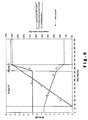
- MLSS bio is maintained at a relatively high level of for example 6.5 g/l as illustrated in Figures 5 and 6 .
- MLSS bio is controlled so that in the first mode MLSS bio is (on average) at least 20%, preferably at least 30% and more preferably at least 40% larger than a reference value.
- This reference value is for example the average of MLSS bio during the first mode and of MLSS bio during the second mode, and is preferably larger than 2 g/l, more preferably larger than 3 g/l, but smaller than 10 g/l, preferably smaller than 8 g/l.
- the average value of MLSS bio is further preferably smaller in the first mode than 12 g/l, and more preferably smaller than 10 g/l.
- Q r,ft is controlled so that MLSS ft is kept below a predetermined maximum MLSS value for the membrane filtration system (for example smaller than 20 g/l).
- MLSS ft is preferably only somewhat higher than MLSS bio and is, more preferably lower than MLSS ft maintained, as explained hereinafter, in the membrane filtration system in the second mode.
- MLSS bio is decreased and respectively increased but usually to a lesser extent (the bioreactor system has usually a larger volume than the membrane filtration system).
- MLSS bio In case MLSS bio would become too high, it can be reduced by removing excess sludge (mixed liquor retentate) via duct 29 out of the installation. Although this could also be automated, removing excess sludge will usually be done in practice by an operator who periodically will control MLSS bio of the bioreactor system. In the example illustrated in Figures 5 and 6 , MLSS ft is maintained on average at about 9 g/l. Due to the relatively small difference between MLSS bio and MLSS ft the sludge recycling factor R will generally be quite large in the first mode, and will normally be larger than 1.5, more particularly even larger than 2.
- Q inf is within a second predetermined range.
- the second range is higher than the first range but may overlap with the first range.
- the settling tank 7 has been filled and the bioreactor effluent is both supplied to the membrane filtration system 25 and to the settling tank system 7 so that there is an effluent from the membrane filtration system (Q eff,ft > 0) and an effluent from the setting tank system (Q eff,st > 0).
- Q eff,ft is preferably higher than 0.5 x Q eff,ft,max , more preferably higher than 0.7 x Q eff,ft,max , and most preferably higher than 0.9 x Q eff,ft,max .
- Q eff,st is thus equal to Q inf - Q eff,ft (on average as mentioned hereabove).
- MLSS bio is however maintained at a relatively low level of for example 2 g/l as illustrated in Figures 5 and 6 . In this way, the bioreactor effluent can also be effectively clarified in the settling tank system 7.
- MLSS bio is controlled so that in the second mode MLSS bio is (on average) at least 20%, preferably at least 30% and more preferably at least 40% smaller than the above-mentioned reference value.
- the average value of MLSS bio in the second mode is further preferably higher than 1 g/l.
- Q r,ft is controlled so that MLSS ft is kept below a predetermined maximum MLSS value for the membrane filtration system (for example smaller than 20 g/l).
- MLSS ft is higher than MLSS bio and is more preferably higher than MLSS ft maintained, as explained hereabove, in the membrane filtration system in the first mode.
- MLSS bio is decreased and respectively increased.
- MLSS bio can also be increased and decreased by recycling more or less activated sludge from the settling tank system 7 to the bioreactor system.
- MLSS bio would become too high, it can be reduced by removing excess sludge out of the installation, preferably via duct 29.
- removing excess sludge will usually be done in practice by an operator who periodically will control MLSS bio of the bioreactor system.
- MLSS ft is maintained on average at about 14 g/l. Due to the relatively big difference between MLSS bio and MLSS ft the sludge recycling factor R will generally be quite small in the second mode, and will normally be smaller than 1.5, more particularly even smaller than 1.
- Transition phase A transition from mode 1 to mode 2: DWF to RWF
- the settling tank When operating the installation in mode 1, and when Q inf raises above said first predetermined range, i.e. when not all of the influent can be treated over the membrane filtration system 25, there has to be switched from the first to the second mode.
- the settling tank In the first mode the settling tank was empty.
- the settling tank 7 is filled with bioreactor effluent (Q s,st > 0).
- the settling tank could be filled with the excess of bioreactor effluent which can not be treated in the membrane filtration system 25.
- At least a portion of the activated sludge contained in the settling tank is supplied during this filling step to the membrane filtration system so that Q eff,ft is still preferably higher than 0.5 x Q eff,ft,max , more preferably higher than 0.7 x Q eff,ft,max , and most preferably higher than 0.9 x Q eff,ft,max .
- the produced effluent is still of the same high purity and, when filled, the effluent from the settling tank will also be immediately of a better quality.
- MLSS ft is indeed preferably increased to store activated sludge flocs in the membrane filtration system which can later on, when switching back to the first mode, be used to achieve a faster increase of MLSS bio .
- MLSS ft is preferably raised with at least 10%, more preferably with at least 20% and most preferably with at least 30%.
- Transition phase B transition from mode 1 to mode 2: DWF to RWF
- Transition phase C transition from mode 2 to mode 1: RWF to DWF
- MLSS ft is preferably lowered by increasing the sludge recycling factor over the membrane filtration system R to the bioreactor system.
- MLSS ft is preferably lowered with at least 10%, more preferably with at least 20% and most preferably with at least 30%.
- Transition phase D transition from mode 2 to mode 1: RWF to DWF
- the water treatment process is performed substantially in the same way as described hereabove for the first mode.
- the settling tank is further emptied in the bioreactor system to increase MLSS bio .
- the settling tank is empty or nearly empty, it can be rinsed out, for example with some bioreactor effluent or even with some purified wastewater.
- the process is in this second mode identical to the process as described hereabove for the situation wherein the settling tank is emptied when switching from the second to the first mode.
- Transition phase A transition from mode 1 to mode 2: DWF to RWF
- MLSS ft is also raised by reducing the recycling factor over the membrane filtration system.
- a portion of the bioreactor effluent is preferably also fed to the membrane filtration system to prevent immediate overloading of the settling tank. Activated sludge is thus also allowed to accumulate in the membrane filtration system.
- the process can further be controlled in the same way as in the second mode.
- Transition phase B transition from mode 1 to mode 2: DWF to RWF
- phase A is terminated and the water treatment process can be performed substantially in the same way as described hereabove for the second mode.
- a smaller amount of activated sludge accumulated in the settling tank can further be recycled to the bioreactor system to further lower MLSS bio if MLSS bio would still be too high (for mode 2).
- Transition phase C transition from mode 2 to mode 1: RWF to DWF
- MLSS ft is also lowered by increasing the recycling factor over the membrane filtration system to increase MLSS bio .
- MLSS bio can further be increased by recycling more activated sludge from the settling tank system to the bioreactor system. The process can further be controlled in the same way as in the first mode.
- Transition phase D transition from mode 2 to mode 1: RWF to DWF
- the water treatment process is performed substantially in the same way as described hereabove for the first mode.
- a larger amount of activated sludge accumulated in the settling tank can further be recycled to the bioreactor system to further raise MLSS bio .
- the membrane filtration system and the settling tank system are both used to store activated sludge flocs when MLSS bio is to be lowered when switching from the first mode to the second mode and are also used to supply activated sludge flocs again to the bioreactor system when MLSS bio is to be raised again when switching from the second mode to the first mode.
- the membrane filtration system preferably comprises a volume of mixed liquor retentate which is larger than which is larger than 10%, preferably larger than 15%, more preferably larger than 20%, of the volume of the mixed liquor contained in said bioreactor system.
- the settling tank system has preferably a volume which is larger than 10%, preferably larger than 20%, and more preferably larger than 30% of the volume of mixed liquor contained in said bioreactor system.
- MLSS ft will normally also be controlled automatically, usually based on Q eff,ft . If the suspended solids content in the installation becomes too high, especially if MLSS bio becomes too high, this will normally be controlled by an operator who will verify whether, depending on whether the installation is in the first or in the second mode, excess sludge has to be removed. This will be done periodically, for example once a day or once a week.
Landscapes
- Life Sciences & Earth Sciences (AREA)
- Water Supply & Treatment (AREA)
- Microbiology (AREA)
- Hydrology & Water Resources (AREA)
- Engineering & Computer Science (AREA)
- Environmental & Geological Engineering (AREA)
- Biodiversity & Conservation Biology (AREA)
- Chemical & Material Sciences (AREA)
- Organic Chemistry (AREA)
- Health & Medical Sciences (AREA)
- Molecular Biology (AREA)
- Separation Using Semi-Permeable Membranes (AREA)
- Activated Sludge Processes (AREA)
Abstract
Description
- The present invention relates to a process for treating wastewater as defined in the preamble of
claim 1 and to an installation for treating wastewater as defined in the preamble ofclaim 14. The wastewater is treated in at least one bioreactor system in the form of a mixed liquor containing activated sludge and at least a portion of the effluent of the bioreactor system is filtrated in a membrane filtration system and, at least when the wastewater influent flow rate is too high for the membrane filtration system, a further portion of the bioreactor effluent is clarified in at least one settling tank. - The process more particularly comprises the steps of:
- feeding the wastewater at a flow rate Qinf to a bioreactor system;
- leading the wastewater in the form of a mixed liquor containing activated sludge through the bioreactor system, the mixed liquor leaving said bioreactor system as a bioreactor effluent which has a mixed liquor suspended solids content MLSSbio;
- performing the wastewater treatment in accordance with a first mode, for a flow rate Qinf which is within a first range, and in accordance with a second mode, for a flow rate Qinf which is within a higher, second range and switching between both modes depending on the magnitude of Qinf;
- supplying both in said first and in said second mode at least a portion of the bioreactor effluent to a membrane filtration system wherein said portion of the bioreactor effluent is filtrated to produce a purified waste water stream at a flow rate Qeff,ft and a mixed liquor retentate which has a mixed liquor suspended solids content MLSSft;
- recycling both in said first and in said second mode at least a portion of said mixed liquor retentate at a flow rate Qr,ft to said bioreactor system; and
- supplying at least in said second mode a further portion of the bioreactor effluent to a settling tank system which comprises at least one settling tank wherein said further portion of the bioreactor effluent is clarified to produce a further purified waste water stream and a further mixed liquor containing settled activated sludge, at least a portion of the further mixed liquor being recycled at a flow rate Qr,st,bio to said bioreactor system.
- In general a wastewater treatment process can comprise mechanical, physico-chemical or biological processes and each combination thereof. Examples of mechanical processes are (i) removal of grit material or other particulate matter by screening, (ii) removal of sand in a sand trap, (iii) removal of particulate matter in a settling tank using gravitation, etc. Examples of physico-chemical processes are (i) precipitation of phosphate or sulphide by dosing Fe(2+) or Fe(3+) salts, (ii) coagulation or flocculation of suspended matter by dosing coagulating or flocculating agents, etc. Examples of biological processes are (i) microbial removal of chemical oxygen demand (COD) or biological oxygen demand (BOD), (ii) microbial removal of nitrogen, (iii) microbial removal of phosphate, etc..
- Said mechanical, physico-chemical or biological processes can be operated in separate or in combined process units. An example of a combined process unit is the dosing of Fe(3+) salts for precipitation of phosphate in a settling tank for settling and separation of the precipitated phosphate.
- A biological wastewater treatment process usually involves activated sludge or biofilm processes that take place in what is further referred to as a bioreactor, that consists of one or more process units or compartments, or as a bioreactor system which comprises one or more bioreactors. When using activated sludge, the wastewater is mixed with activated sludge resulting in a stream further referred to as mixed liquor, and that is led through the bioreactor. The mixing occurs usually in a process unit that is usually referred to as the selector. In general the mixed liquor can be described as a complex aqueous suspension or solution of inorganic and organic matter. The organic matter is in part comprised of microbial active organisms of the activated sludge that are involved in the biological processes such as e.g. BOD removal, COD removal, nitrogen removal, phosphorus removal, etc. for treatment of the wastewater. The microbial active organisms in activated sludge are at least in part grouped in a structure of flocs suspended in the mixed liquor.
- The concentration of activated sludge in mixed liquor is usually expressed as Mixed Liquor Suspended Solids (MLSS), e.g. 4 g MLSS/I. For determining the MLSS value of mixed liquor, standard methods exist corresponding to the determination of Total Suspended Solids (TSS) in the mixed liquor. The determination of TSS is described for example in "Eaton A.D., Clesceri L.S. & Greensberg A.E. (1995). Standard methods for the examination of water and wastewater (19th edition), prepared and published jointly by American Public Health Association, American Water Works Association and Water Environment Association".
- Said mixed liquor allows further treatment of the wastewater under specific conditions. Said specific conditions can be aerobic (i.e. dissolved oxygen is present), anoxic (i.e. dissolved oxygen is not present and dissolved nitrite or dissolved nitrate are present), anaerobic (i.e. dissolved oxygen, dissolved nitrite and dissolved nitrate are not present) conditions or intermediate conditions between aerobic, anoxic and anaerobic conditions. Said specific conditions can be discriminated in time or in space. In time, discrimination can occur by e.g. discontinuous aeration of said mixed liquor. In space, discrimination can occur by e.g. using different holding or reactor tanks for said mixed liquor. Discrimination in space can also occur on a microscopic level within the different layers of sludge flocs in said mixed liquor of activated sludge systems or in biofilms of biofilm processes. Said specific conditions can occur in typical process units used in biological treatment systems such as the selector, the anaerobic reactor or the oxidation ditch.
- The biological treatment implies that a clarification step of the mixed liquor flowing out of the bioreactor system (bioreactor effluent) is required wherein the activated sludge is separated from the treated wastewater. The separated activated sludge is at least in part contained in a mixed liquor stream showing a higher MLSS concentration. In conventional activated sludge processes (CAS), said separation is done by using a settling tank wherein the separation occurs through gravity that forces the settling of the activated sludge flocs and other suspended components. Other possible separation processes are flotation or (membrane) filtration. The said separated activated sludge is returned to the biological process for mixing with wastewater and/or said separated activated sludge is in part not returned to the biological treatment but undergoes further treatment and disposal. Said not returned part is further referred to as the excess sludge. Further treatment of excess sludge can comprise e.g. sludge thickening by gravitation or a filter belt, sludge digestion, dewatering by a centrifuge, sludge drying, etc.
- A typical prior art process configuration for wastewater treatment in presented in
Figure 1 . The wastewater is collected at the receiving point (1) from which it flows (2) to a mechanical treatment (3) and subsequently flows (4) to a bioreactor system (5) using activated sludge. After biological treatment, the mixed liquor (6) flows to a settling tank (7) in which the activated sludge is separated from the purified wastewater by settling of the activated sludge flocs and other suspended components. The purified wastewater removed (8) from the settling tank (7) flows (8) to the discharge point (9). The separated sludge removed (10) from the settling tank (7) is returned (12) to the bioreactor system (5) or in part removed (13) for sludge treatment (14) and disposal (16). A typical process configuration according toFigure 1 can also include several settling tanks in parallel operation. - When collecting a wastewater stream characterised by strong variations in flow rate it is in most cases not possible to treat at all time the complete flow in the bioreactor system. One reason for this is that the hydraulic capacity of the settling tank is limited. Too high flow rates to the settling tank will result in too high flow rates within the settling tank and a bad settling of the sludge flocs and other suspended components. The latter will result in the discharge of activated sludge with the treated wastewater. A typical example of a situation where strong variations in collected wastewater flow rate exist is the collection of municipal wastewater collected in a combined sewer system. A combined sewer system is a sewer system that collects e.g. as well household wastewater as run-off water from parkings, roofs, streets, .... The wastewater collected by a combined sewer system can thus collect a significant higher flow rate during rain weather conditions (i.e. the rain weather flow - RWF) in comparison with dry weather conditions (i.e. the dry weather flow - DWF).
- A known solution to circumvent the problem of varying wastewater flow rates and to safeguard the performance of the settling tank in a CAS (Conventional Activated Sludge - cf.
Figure 1 ) system by limiting its hydraulic loading is to split up the wastewater stream before the biological treatment and to give the separated stream an additional separate treatment without biological treatment. An example of this is given by the separate extension of the mechanical treatment for said separated wastewater stream not flowing to the biological treatment. A typical process configuration illustrating this principle is presented inFigure 2 . After a mechanical treatment (3), the wastewater stream is split up (17). One part flows (18) to a bioreactor system (5), the other part flows (19) to a storm water tank (20). In said storm water tank (20), the wastewater undergoes an additional mechanical treatment by settling of suspended material. The wastewater removed (21) from the storm water tank (20) is mixed (22) with the wastewater removed (8) from the settling tank (7) and flows (23) to the discharge point (9). The settled material removed (24) from the storm water tank can be returned to the receiving point (1) of the collected wastewater. - A disadvantage of applying a separation of activated sludge and wastewater by means of gravitation in a settling tank is the fact that the performance of the separation process is largely depending on the physical properties of the sludge flocs, the mixed liquor suspended solids (MLSS) concentration, the configuration of the settling tank and the operation (e.g. the previously mentioned hydraulic loading) of the settling tank. A low performance of the separation process can result in a deterioration of the quality of the treated wastewater as it will contain still a significant amount of suspended matter.
- Another disadvantage of applying a separation of activated sludge and wastewater by means of gravitation in a settling tank is the fact that, in practice due to economic reasons, the volume of settling tanks is limited such that the maximum allowable MLSS concentration to obtain a good separation is limited to the order of 4-5 g MLSS/I. This implies that the MLSS concentration of the mixed liquor in the biological treatment process is also limited to this range. The latter limits the treatment capacity of the biological process per unit reactor volume and results in rather high footprint requirements, i.e. the installation requires a quite large surface area.
- A solution to circumvent the problem of the limitation of MLSS concentration of mixed liquor in the range of 4-5 g MLSS/I and the problem of the impact of the physical properties of the sludge floc on the activated sludge - wastewater separation process, is the use of membranes for separation of the activated sludge from the treated wastewater. Membrane bioreactors (MBRs) combine membrane processes with biological processes for the treatment of wastewater. Membranes when coupled to biological processes are most often used as a replacement for separation of activated sludge and purified wastewater by means of gravitation in a settling tank. In MBRs said separation is done by using membranes which separate the activated sludge from the treated wastewater by filtration. In wastewater treatment, the driving force for this process is usually a pressure gradient, although also other mechanisms can be used to force media through a membrane (e.g. a concentration gradient or an electrical potential difference). Said pressure gradient over the membrane can be applied by gravity (i.e. by the hydraulic head of the mixture above the membrane) or mechanically (i.e. by pumps).
- Compared to the CAS process, applying MBRs for wastewater treatment offers two basic advantages. First of all MBRs generate a much better effluent quality, since by definition complete retention of suspended matter (e.g. activated sludge, bacteria) or components adsorbed to them is attainable. Secondly MBRs allow to build more compact, since they allow to work at a higher mixed liquor suspended solids (MLSS) concentration, typically in the range of 10-20 g MLSS/I.
- A typical prior art MBR configuration for wastewater treatment is presented in
Figure 3 . The wastewater is collected at the receiving point (1) from which it flows (2) to a mechanical treatment (3), mostly comprising a fine screen of minimum 3 mm, and subsequently flows (4) in series to a bioreactor system (5) using activated sludge. After biological treatment, the mixed liquor (6) flows to a membrane filtration tank (25) in which mixed liquor is separated by filtration into a filtrate (26), i.e. the purified wastewater, and a retentate (27), i.e. the mixed liquor stream retaining the activated sludge. The filtrate (26) flows to the discharge point (9). Activated sludge from the membrane filtration tank (25) is recycled (28) to the bioreactor system (5) or is in part removed (29) for sludge treatment (14) and disposal (16) (to avoid that the MLSS content in the bioreactor and/or in the membrane filtration tank would become too high). - A major disadvantage restricting a widespread application of MBRs for wastewater treatment is the fact that the membrane component cost is more or less proportional to plant size (i.e. total influent flow) as opposed to the clarifying component in a CAS system showing a downward economy of scale. In addition, the total membrane surface area in an MBR has to be designed based on the maximal flow to be treated biologically, where a higher flow variation results in more membrane surface area. As a result MBRs are rarely financially beneficial in case the wastewater flow is either very large or in case the flow rate is characterised by strong variations.
- In practice, hybrid wastewater treatment systems have therefore been proposed to reduce the membrane component cost (see for example the MBR Special III issue of April 2005 of the "
H 20 Magazine for water supply and water management". These systems comprise a CAS tank (= first bioreactor or the bioreactor system), a settling tank arranged downstream the CAS tank and an MBR (comprising a second bioreactor belonging to the membrane filtration system and the actual membrane filtration tank). In the known parallel configuration the wastewater influent is split over the CAS tank and the MBR, during rain weather conditions a larger portion of the influent being fed to the CAS tank. In the known in-series-hybrid configuration, all the wastewater influent is fed to the CAS tank. During dry weather conditions, all of the CAS effluent is fed to the MBR whilst during rain weather conditions a portion of the CAS effluent is treated in the settling tank. The wastewater treatment is thus performed in accordance with a first mode, for a low influent flow rate, and in accordance with a second mode, for a higher influent flow rate, and depending on the magnitude of the influent flow rate there is switched between both modes. - A drawback of the known hybrid systems is that it is always necessary to build, control and maintain two biological treatment systems and that the treatment capacity per unit reactor volume of the biological process in the CAS tank is still limited.
- An object of the present invention is therefore to provide a hybrid wastewater treatment system, comprising at least one membrane filtration system and at least one settling tank, wherein the treatment capacity of the bioreactor system is higher per unit reactor volume than in a CAS tank.
- To this end the wastewater treatment is also performed in accordance with the above described first and second mode but, when switching from the first to the second mode, the mixed liquor suspended solids content (MLSSbio) of the bioreactor effluent is adjusted by introducing more or less activated sludge in the bioreactor system so that in the first mode MLSSbio is larger than in the second mode.
- When performing the wastewater treatment in accordance with the first mode (i.e. when the influent flow rate Qinf to the bioreactor system is relatively small, for example during dry weather conditions) the bioreactor volume is thus more effectively used for the biological conversion processes so that, on average, the treatment capacity of the bioreactor system is increased per unit reactor volume.
- In a preferred embodiment, the process according to the invention is characterised in that, when switching from said first to said second mode, the sludge recycling factor over the membrane filtration system Qr,ft/Qeff,ft is decreased to raise MLSSft and to lower MLSSbio and vice versa, when switching from said second to said first mode, the sludge recycling factor over the membrane filtration system Qr,ft/Qeff,ft is increased to lower MLSSft and to raise MLSSbio.
- This preferred embodiment enables to store at least a portion of the activated sludge, which has to be removed from the bioreactor system to lower MLSSbio, in the membrane filtration system when Qinf increases so that the process has to be switched to the second mode and to increase MLSSbio more quickly again when Qinf decreases so that the process has to be switched to the first mode.
- In a further preferred embodiment, the process according to the invention is characterised in that, when switching from said second to said first mode, at least a portion of the activated sludge which has been accumulated in the settling tank is recycled to the bioreactor system to raise MLSSbio. Activated sludge can be accumulated in the settling tank in particular when switching from said first to said second mode and/or when performing the wastewater treatment in said second mode.
- This preferred embodiment therefore also allows to increase MLSSbio more quickly again when Qinf decreases so that the process has to be switched to the first mode.
- Preferably, when switching from said second to said first mode, the volume of further mixed liquor contained in the settling tank (7) is lowered, preferably until the settling tank (7) is substantially empty and, when changing from said first to said second mode, the settling tank (7) is filled again with bioreactor effluent. In this way, the capacity of the settling tank to store activated sludge from the bioreactor system and to supply it again to the bioreactor system is optimally used.
- More preferably, when filling the settling tank at least a portion of the activated sludge contained therein is recycled to the membrane filtration system, the supply of bioreactor effluent to the membrane filtration system being preferably interrupted when receding the activated sludge from the settling tank to the membrane filtration system. In this way, a better clarification will be achieved in the settling tank when it is filled and MLSSft will increase more effectively, especially when, at least during an initial phase of filling the settling tank, no mixed liquor is recycled from the membrane filtration system to the bioreactor system.
- Other particularities and advantages of the invention will become apparent from the following description of some particular embodiments of the process and the installation according to the present invention. The reference numerals used in this description relate to the annexed drawings wherein:
-
Figure 1 illustrates schematically a prior art conventional activated sludge (CAS) wastewater treatment system; -
Figure 2 illustrates schematically a same CAS treatment system as illustrated inFigure 1 but supplemented with a storm weather tank; -
Figure 3 illustrates schematically a prior art membrane bioreactor (MBR) wastewater treatment system; . -
Figure 4 illustrates schematically a hybrid wastewater treatment system according to the present invention; -
Figure 5 shows a graph of the evolution of the MLLS values in the bioreactor system and in the membrane filtration system when switching from the first mode (DWF) to the second mode (RWF) and also shows a graph of the filling of the settling tank during this switching; and -
Figure 6 shows a graph similar to the graph ofFigure 5 but illustrating the MLLS values and the draining of the settling tank when switching from the second (RWF) to the first mode (DWF). - A preferred embodiment of the present invention is presented in
Figure 4 . The wastewater is collected at areceiving point 1 from which it is continuously delivered through aduct 2 to a mechanical treatment system 3 (mostly comprising a fine screen of minimum 3 mm). The mechanically treated wastewater subsequently flows at a (variable) flow rate Qinf, through aduct 4, to abioreactor system 5 wherein the wastewater is mixed with activated sludge to produce a mixed liquor. After the biological treatment in thebioreactor system 5, the mixed liquor stream leaving the bioreactor system is split up, at least under rain weather conditions, at 30 into two portions (i.e. two flows): one portion which is supplied both under dry and under rain weather conditions at a flow rate Qs,ft, through aduct 31, to amembrane filtration system 25 comprising at least one membrane filtration tank, and a more variable portion, caused by rain weather conditions, which flows at a flow rate Qs,st through aduct 32 to asettling tank system 7 which comprises at least one settling tank. In the settling tank 7 a further mixed liquor containing the settled activated sludge is separated from the wastewater by gravitation. When the settling tank is full, the separated sludge removed from thesettling tank 7 is returned at a flow rate Qr,st,bio, through aduct 10, to thebioreactor system 5. In themembrane filtration system 25 the activated sludge, more particularly a mixed liquor retentate containing the activated sludge, is separated from the wastewater by filtration. The separated wastewater, which is removed at a flow rate Qeff,ft, through aduct 26, from themembrane filtration tank 25, is mixed at 33 with the wastewater which is removed at a flow rate Qeff,st, through aduct 8, from the settling tank 7 (at least when the settling tank is filled and Qs,st is larger than Qr,st,bio or larger than the sum of Or,st,bio and Qr,st,ft when some of the mixed liquor would also be recycled from the settling tank to the membrane filtration tank). Said mixture flows through aduct 34 to adischarge point 9. Mixed liquor retentate from themembrane filtration system 25 is recycled at a flow rate Qr,ft, through aduct 27, to thebioreactor system 5 or is in part removed (excess sludge) through aduct 29 for sludge treatment at 14 and disposal at 16. - The installation illustrated in
Figure 4 is especially suited to enable to empty thesettling tank 7 during dry weather conditions and to fill it again during rain weather conditions. To enhance the storage of activated sludge in the filtration tank, and to achieve, once filled, immediately a better clarification in thesettling tank 7, anadditional duct 35 is provided which enables to recycle activated sludge from the settling tank, at a flow rate Qr,st,ft, to themembrane filtration system 25, and this during the initial phase that the settling tank is being filled. For the same reason, the recycling of mixed liquor retentate from the membrane filtration tank to the bioreactor system is interrupted during the initial phase of filling the settling tank. As a consequence, the flow rate of the purified wastewater produced by the filtration tank, Qeff,ft, equals to flow rate of the recycle stream from the settling tank, Or,st,ft (if Qs,ft = 0). - The preferred installation has only been illustrated schematically in
Figure 4 . More particularly the structure or composition of each of the components of the installation has not been represented since they are known per se. Thebioreactor system 5 comprises for example a bioreactor which consists of several compartments through which the mixed liquor is led. Although the presence of only one bioreactor is preferred in view of reducing the installation and operational costs, thebioreactor system 5 may comprise two or even more bioreactors. After the flow of bioreactor effluent is split at 30, themembrane filtration system 25 and thesettling tank system 7 begin. - The
membrane filtration system 25 may comprise only one membrane filtration tank or more membrane filtration tanks, which are preferably arranged in parallel. Themembrane filtration system 25 may also comprise an additional bioreactor (MBR) but such an additional bioreactor is again not preferred so that themembrane filtration system 25 preferably contains no additional bioreactor. In this respect it should be noted that, although membrane filtration tanks are aerated with course air bubbles to clean the membranes, such membrane filtration tanks are not to be considered as bioreactors. - The
settling tank system 7 may comprise only one settling tank or more settling tanks, which are preferably arranged in parallel. Although it is possible to provide an additional bioreactor in thesettling tank system 7, this is again not preferred. - In the process according to the invention, the wastewater is fed at a flow rate Qinf to the bioreactor system. This wastewater may be industrial wastewater but will usually be municipal wastewater. The installation is preferably constructed to be able to treat Qinf flow rates varying for example between a very small flow rate (below 1014, i.e. the dry weather flow, not including parasitic water such as e.g. infiltration water into the sewer system, multiplied by 1 and 24/14) and 6Q14.
- The wastewater is led in the form of a mixed liquor, which contains activated sludge recycled from the
membrane filtration system 25 and/or from thesettling tank system 7, through thebioreactor system 5. Due to the addition of activated sludge to the wastewater and the generation of additional activated sludge flocs in the bioreactor system, the mixed liquor has in the last compartment of thebioreactor system 5, i.e. in the bioreactor effluent which is split over both separation systems, a predetermined mixed liquor suspended solids content MLSSbio. - The portion of the bioreactor effluent supplied to the
membrane filtration system 25 is filtrated to produce the purified wastewater stream at the flow rate Qeff,ft and an activated sludge fraction which is intended to be recycled (Qr,ft) to thebioreactor system 5 and which has an MLSS content MLSSft, which is normally larger than MLSSbio. - An essential feature of the process according to the invention is that the wastewater treatment is performed in accordance with two modes, namely in accordance with a first mode for a flow rate Qinf which is within a first range, and in accordance with a second mode, for a flow rate Qinf which is within a higher, second range (which may overlap with the first range) and that there is switched between both modes depending on the magnitude of Qinf. Switching between the two modes can be done based on a direct or indirect measurement of Qinf, for example by measuring the average magnitude of Qinf during a predetermined period of time (for example greater than one hour), by measuring the water level in a tank wherein the water level fluctuates in depending on Qinf or by measuring for example an indirect parameter such as the ammonium content of the fed wastewater (diluted under rain weather conditions).
- A further essential feature of the process according to the invention is that when switching between the two operational modes, MLSSbio is adjusted so that in the first mode MLSSbio is larger than in the second mode. In the first mode, the bioreactor effluent is entirely or at least mainly supplied to the membrane filtration system so that the purified wastewater can be effectively separated from the activated sludge notwithstanding the high MLSS content of the bioreactor effluent. In this mode, the
bioreactor system 5 has a higher treatment capacity per volume unit than in the prior art hybrid configurations. In the second mode, MLSSbio is then again lowered since a large portion of the bioreactor effluent has to be clarified in thesettling tank system 7. - The operation of the process in the first and in the second mode and the transitions between these two modes will now be explained more into detail. Reference is made to the graphs shown in
Figures 5 and6 . When relationships between different flow rates are given, it should be noted that these relationships are only average relationships and do not take into account any fluctuations of the liquid levels in the different tanks or compartments or any time delays. - Two different situations are described, namely first a preferred embodiment wherein the settling tank is filled and emptied during the transition between the two operational modes and a less preferred embodiment wherein the settling tank remains full.
- When the process is operated in the first mode, Qinf is within a first predetermined range. In this mode the
settling tank 7 is empty and there is thus no settling tank effluent (Qeff,st = 0) and also no recycling of activated sludge from the settling tank (Qr,st,bio = 0 and Qr,st,ft = 0). All of the effluent will be produced by the membrane filtration system so that Qeff,ft = Qinf (on average as mentioned hereabove). The first predetermined range of Qinf is thus determined by the maximum capacity of the membrane filtration system Qeff,ft,max, this range being preferably from 0 to 0.5 x Qeff,ft,max, more preferably from 0 to 0.7 x Qeff,ft,max, and most preferably from 0 to 0.9 x Qeff,ft,max. - A certain amount of the mixed liquor retentate produced in the
membrane filtration system 25 is recycled at the flow rate Qr,ft to the bioreactor system. MLSSbio is maintained at a relatively high level of for example 6.5 g/l as illustrated inFigures 5 and6 . In general, MLSSbio is controlled so that in the first mode MLSSbio is (on average) at least 20%, preferably at least 30% and more preferably at least 40% larger than a reference value. This reference value is for example the average of MLSSbio during the first mode and of MLSSbio during the second mode, and is preferably larger than 2 g/l, more preferably larger than 3 g/l, but smaller than 10 g/l, preferably smaller than 8 g/l. The average value of MLSSbio is further preferably smaller in the first mode than 12 g/l, and more preferably smaller than 10 g/l. - Qr,ft is controlled so that MLSSft is kept below a predetermined maximum MLSS value for the membrane filtration system (for example smaller than 20 g/l). MLSSft is preferably only somewhat higher than MLSSbio and is, more preferably lower than MLSSft maintained, as explained hereinafter, in the membrane filtration system in the second mode. MLSSft can be increased by decreasing the sludge recycling factor R over the membrane filtration system (R = Qr,ft/Qeff,ft) and can be decreased by increasing the sludge recycling factor. At the same time, MLSSbio is decreased and respectively increased but usually to a lesser extent (the bioreactor system has usually a larger volume than the membrane filtration system). In case MLSSbio would become too high, it can be reduced by removing excess sludge (mixed liquor retentate) via
duct 29 out of the installation. Although this could also be automated, removing excess sludge will usually be done in practice by an operator who periodically will control MLSSbio of the bioreactor system. In the example illustrated inFigures 5 and6 , MLSSft is maintained on average at about 9 g/l. Due to the relatively small difference between MLSSbio and MLSSft the sludge recycling factor R will generally be quite large in the first mode, and will normally be larger than 1.5, more particularly even larger than 2. - When the process is operated in the second mode, Qinf is within a second predetermined range. The second range is higher than the first range but may overlap with the first range. In this mode the
settling tank 7 has been filled and the bioreactor effluent is both supplied to themembrane filtration system 25 and to thesettling tank system 7 so that there is an effluent from the membrane filtration system (Qeff,ft > 0) and an effluent from the setting tank system (Qeff,st > 0). Since the effluent from the membrane filtration system is of a higher purity than the effluent of the settling tank system, Qeff,ft is preferably higher than 0.5 x Qeff,ft,max, more preferably higher than 0.7 x Qeff,ft,max, and most preferably higher than 0.9 x Qeff,ft,max. Qeff,st is thus equal to Qinf - Qeff,ft (on average as mentioned hereabove). - In the second mode, activated sludge is not only recycled from the membrane filtration system to the bioreactor system (Qr,ft > 0) but also from the settling tank system to the bioreactor system (Qr,st,bio > 0). MLSSbio is however maintained at a relatively low level of for example 2 g/l as illustrated in
Figures 5 and6 . In this way, the bioreactor effluent can also be effectively clarified in thesettling tank system 7. In general, MLSSbio is controlled so that in the second mode MLSSbio is (on average) at least 20%, preferably at least 30% and more preferably at least 40% smaller than the above-mentioned reference value. The average value of MLSSbio in the second mode is further preferably higher than 1 g/l. - Qr,ft is controlled so that MLSSft is kept below a predetermined maximum MLSS value for the membrane filtration system (for example smaller than 20 g/l). MLSSft is higher than MLSSbio and is more preferably higher than MLSSft maintained, as explained hereabove, in the membrane filtration system in the first mode. Also in the second mode MLSSft can be increased by decreasing the sludge recycling factor R over the membrane filtration system (R = Qr,ft/Qeff,ft) and can be decreased by increasing the sludge recycling factor. At the same time, MLSSbio is decreased and respectively increased. In the second mode, MLSSbio can also be increased and decreased by recycling more or less activated sludge from the
settling tank system 7 to the bioreactor system. In case MLSSbio would become too high, it can be reduced by removing excess sludge out of the installation, preferably viaduct 29. Although this could also be automated, removing excess sludge will usually be done in practice by an operator who periodically will control MLSSbio of the bioreactor system. In the example illustrated inFigures 5 and6 , MLSSft is maintained on average at about 14 g/l. Due to the relatively big difference between MLSSbio and MLSSft the sludge recycling factor R will generally be quite small in the second mode, and will normally be smaller than 1.5, more particularly even smaller than 1. - When operating the installation in
mode 1, and when Qinf raises above said first predetermined range, i.e. when not all of the influent can be treated over themembrane filtration system 25, there has to be switched from the first to the second mode. In the first mode the settling tank was empty. During the transition phase A thesettling tank 7 is filled with bioreactor effluent (Qs,st > 0). The settling tank could be filled with the excess of bioreactor effluent which can not be treated in themembrane filtration system 25. However, all of (or preferably at least halve of) the bioreactor effluent is preferably supplied during this phase to the settling tank system (Qs,st = Qinf or Qs,st is preferably larger than 0.5 x Qinf). At least a portion of the activated sludge contained in the settling tank is supplied during this filling step to the membrane filtration system so that Qeff,ft is still preferably higher than 0.5 x Qeff,ft,max, more preferably higher than 0.7 x Qeff,ft,max, and most preferably higher than 0.9 x Qeff,ft,max. In this way, the produced effluent is still of the same high purity and, when filled, the effluent from the settling tank will also be immediately of a better quality. - Another advantage is that by recycling activated sludge to the
membrane filtration system 25, it is possible to achieve a quick accumulation of activated sludge flocs in the membrane filtration system. When switching from the first to the second mode, MLSSft is indeed preferably increased to store activated sludge flocs in the membrane filtration system which can later on, when switching back to the first mode, be used to achieve a faster increase of MLSSbio. - To accumulate activated sludge in the membrane filtration system (raise MLSSft), and to decrease MLSSbio, the sludge recycling factor over the membrane filtration system R is preferably decreased. More preferably, recycling of activated sludge from the membrane filtration system to the bioreactor system is stopped (Qr,ft = 0 and R = 0) so that the fastest decrease of MLSSbio and the fastest increase of MLSSft can be achieved. During the transitional phase A, MLSSft is preferably raised with at least 10%, more preferably with at least 20% and most preferably with at least 30%.
- When the desired increased MLSSft level of for example 14 g/l is achieved in the membrane filtration system, recycling of activated sludge from the settling tank to the membrane filtration system is stopped (Qr,st,ft = 0) so that activated sludge can accumulate in the settling tank during the further filling thereof. During phase B, the water treatment process is performed further substantially in the same way as described hereabove for the second mode. The only further differences are that no effluent is produced by the settling tank system (Qeff,st = 0) and that there preferably also no recycling of activated sludge from the settling tank system to the bioreactor system (Qr,st,bio = 0). MLLSbio should indeed be further decreased to achieve the lower MLLSbio value for the second mode.
- When operating the installation in
mode 2, and when Qinf reduces below said second predetermined range, i.e. when it is no longer required to treat a portion of the bioreactor effluent over the settling tank system, there has to be switched from the second to the first mode. In the second mode the settling tank was full. During the transition phase C the supply of bioreactor effluent to the settling tank system is stopped (Qs,st = 0) and thesettling tank 7 is emptied. During the transition from the first mode to the second mode and/or when performing the wastewater treatment in the second mode, activated sludge was allowed to accumulate in the settling tank system. At least a portion of this accumulated active sludge (preferably the entire content of the setting tank system) is now recycled to the bioreactor system to raise MLSSbio (Qr,st,bio > 0). - Just as in the first mode, all of the effluent will be produced by the membrane filtration system so that Qeff,ft = Qinf. (on average as mentioned hereabove). To further raise MLSSbio, MLSSft is preferably lowered by increasing the sludge recycling factor over the membrane filtration system R to the bioreactor system. During the transition phase C, MLSSft is preferably lowered with at least 10%, more preferably with at least 20% and most preferably with at least 30%.
- When the desired reduced MLSSft level of for example 9 g/l is achieved in the membrane filtration system, the water treatment process is performed substantially in the same way as described hereabove for the first mode. The only difference is that the settling tank is further emptied in the bioreactor system to increase MLSSbio. When the settling tank is empty or nearly empty, it can be rinsed out, for example with some bioreactor effluent or even with some purified wastewater.
- In this mode a small amount of bioreactor effluent is continuously or discontinuously recycled over the settling tank system back to the bioreactor system to constantly refresh the activated sludge (mixed liquor) contained therein. When no effluent is removed from the settling tank system (Qeff,st = 0) the process in the first mode is further entirely identical to the process as described hereabove for the situation wherein the settling tank is emptied. It is however now possible to remove a portion of the bioreactor effluent as treated wastewater via the settling tank system (Qeff,st > 0). In that case Qeff,ft is preferably larger than 80% of Qinf or, in other words, Qeff,st is preferably smaller than 20% of Qinf.
- The process is in this second mode identical to the process as described hereabove for the situation wherein the settling tank is emptied when switching from the second to the first mode.
- During this transition phase MLSSft is also raised by reducing the recycling factor over the membrane filtration system. Instead of feeding the membrane filtration system only with activated sludge settled in the settling tank, a portion of the bioreactor effluent is preferably also fed to the membrane filtration system to prevent immediate overloading of the settling tank. Activated sludge is thus also allowed to accumulate in the membrane filtration system. The process can further be controlled in the same way as in the second mode.
- When the desired increased MLSSft level of for example 14 g/l is achieved in the membrane filtration system, phase A is terminated and the water treatment process can be performed substantially in the same way as described hereabove for the second mode. The only difference is that a smaller amount of activated sludge accumulated in the settling tank can further be recycled to the bioreactor system to further lower MLSSbio if MLSSbio would still be too high (for mode 2).
- During this transition phase MLSSft is also lowered by increasing the recycling factor over the membrane filtration system to increase MLSSbio. MLSSbio can further be increased by recycling more activated sludge from the settling tank system to the bioreactor system. The process can further be controlled in the same way as in the first mode.
- When the desired reduced MLSSft level of for example 9 g/l is achieved in the membrane filtration system, the water treatment process is performed substantially in the same way as described hereabove for the first mode. The only difference is that a larger amount of activated sludge accumulated in the settling tank can further be recycled to the bioreactor system to further raise MLSSbio.
- In the above described embodiments, the membrane filtration system and the settling tank system are both used to store activated sludge flocs when MLSSbio is to be lowered when switching from the first mode to the second mode and are also used to supply activated sludge flocs again to the bioreactor system when MLSSbio is to be raised again when switching from the second mode to the first mode. In order to enable to store or accumulate a substantial amount of activated sludge flocs, the membrane filtration system preferably comprises a volume of mixed liquor retentate which is larger than which is larger than 10%, preferably larger than 15%, more preferably larger than 20%, of the volume of the mixed liquor contained in said bioreactor system. The settling tank system, on the other hand, has preferably a volume which is larger than 10%, preferably larger than 20%, and more preferably larger than 30% of the volume of mixed liquor contained in said bioreactor system.
- The data indicated in
Figures 5 and6 are based on the following parameters: - One bioreactor having a volume of 1230 m3
- One membrane filtration tank having a volume of 440 m3
- One settling tank having a volume of 1200 m3
- Maximum total influent flow rate (Qinf,max) is 179 I/s
- Maximum effluent flow rate of the membrane filtration tank (Qeff,ft,max) is 60 I/s
- Maximum effluent flow rate of the settling tank (Qeff,st,max) is 119 l/s
- As to the installation used to perform the process according to the invention, it should be noted that the necessary pumps should be provided to circulate the wastewater through the different components and that an automatic control system is provided to perform the process in the different modes and to switch between these modes. MLSSft will normally also be controlled automatically, usually based on Qeff,ft. If the suspended solids content in the installation becomes too high, especially if MLSSbio becomes too high, this will normally be controlled by an operator who will verify whether, depending on whether the installation is in the first or in the second mode, excess sludge has to be removed. This will be done periodically, for example once a day or once a week.
Claims (15)
- A process for treating wastewater comprising the steps of:- feeding the wastewater at a flow rate Qinf to a bioreactor system (5);- leading the wastewater in the form of a mixed liquor containing activated sludge through the bioreactor system (5), the mixed liquor leaving said bioreactor system (5) as a bioreactor effluent which has a mixed liquor suspended solids content MLSSbio;- performing the wastewater treatment in accordance with a first mode, for a flow rate Qinf which is within a first range, and in accordance with a second mode, for a flow rate Qinf which is within a higher, second range and switching between both modes depending on the magnitude Of Qinf;- supplying both in said first and in said second mode at least a portion of the bioreactor effluent to a membrane filtration system (25) wherein said portion of the bioreactor effluent is filtrated to produce a purified waste water stream at a flow rate Qeff,ft and a mixed liquor retentate which has a mixed liquor suspended solids content MLSSft;- recycling both in said first and in said second mode at least a portion of said mixed liquor retentate at a flow rate Qr,ft to said bioreactor system (5); and- supplying at least in said second mode a further portion of the bioreactor effluent to a settling tank system (7) which comprises at least one settling tank wherein said further portion of the bioreactor effluent is clarified to produce a further purified waste water stream and a further mixed liquor containing settled activated sludge, at least a portion of the further mixed liquor being recycled at a flow rate Qr,st,bio to said bioreactor system (5);characterised in that,
when switching from said first to said second mode and vice versa, MLSSbio is adjusted so that in said first mode MLSSbio is larger than in said second mode. - A process according to claim 1, characterised in that, when switching from said first to said second mode, the sludge recycling factor over the membrane filtration system Qr,ft/Qeff,ft is decreased to raise MLSSft and to lower MLSSbio and vice versa, when switching from said second to said first mode, the sludge recycling factor over the membrane filtration system Qr,ft/Qeff,ft is increased to lower MLSSft and to raise MLSSbio.
- A process according to claim 2, characterised in that when switching from said first to said second mode MLSSft is raised with at least 10%, preferably with at least 20% and more preferably with at least 30%.
- A process according to claim 2 or 3, characterised in that when switching from said second to said first mode MLSSft is lowered with at least 10%, preferably with at least 20% and more preferably with at least 30%.
- A process according to any one of the claims 1 to 4, characterised in that the membrane filtration system (25) contains a volume of said mixed liquor retentate which is larger than 10%, preferably larger than 15%, more preferably larger than 20%, of the volume of mixed liquor contained in said bioreactor system (5).
- A process according to any one of the claims 1 to 5, characterised in that MLSSbio is adjusted so that in said first mode MLSSbio is at least 20%, preferably at least 30% and more preferably at least 40% larger than a reference value and so that in said second mode MLSSbio is at least 20%, preferably at least 30% and more preferably at least 40% smaller than said reference value.
- A process according to claim 6, characterised in that said reference value is larger than 2 g/l, preferably larger than 3 g/l, but smaller than 10 g/l, preferably smaller than 8 g/l.
- A process according to any one of the claims 1 to 7, characterised in that, when switching from said second to said first mode, at least a portion of the activated sludge, which has been accumulated in the settling tank (7), is recycled to the bioreactor system (5) to raise MLSSbio.
- A process according to claim 8, characterised in that, when switching from said second to said first mode, the volume of further mixed liquor contained in the settling tank (7) is lowered, preferably until the settling tank (7) is substantially empty and, when changing from said first to said second mode, the settling tank (7) is filled again with bioreactor effluent.
- A process according to claim 9, characterised in that when filling the settling tank (7) at least a portion of the activated sludge contained therein is recycled to the membrane filtration system (25), the supply of bioreactor effluent to the membrane filtration system (25) being preferably interrupted when recycling the activated sludge from the settling tank (7) to the membrane filtration system (25).
- A process according to any one of the claims 8 to 10, characterised in that the settling tank (7) has a volume which is larger than 10%, preferably larger than 20%, and more preferably larger than 30% of the volume of mixed liquor contained in said bioreactor system (5).
- A process according to any one of the claims 1 to 11, characterised in that, when switching from said first to said second mode, recycling of the mixed liquor retentate produced in the membrane filtration system (25) to the bioreactor system (5) is substantially interrupted.
- A process according to any one of the claims 1 to 12, characterised in that the membrane filtration system comprises at least one membrane filtration tank (25) but no additional bioreactor wherein biological conversion processes are carried out so that additional activated sludge is produced and the settling tank system (7) preferably also does not comprise an additional bioreactor wherein biological conversion processes are carried out so that additional activated sludge flocs are produced, the effluent supplied to the membrane filtration tank (25) and the effluent supplied to the settling tank (7) having preferably substantially the same MLSS content.
- A wastewater treatment installation, comprising:- at least one bioreactor system (5);- means (4) for feeding the wastewater at a flow rate Qinf to said bioreactor system (5) and for leading the wastewater in the form of a mixed liquor containing activated sludge through the bioreactor system (5) to produce a bioreactor effluent;- means for switching between two modes wherein the wastewater treatment can be performed, namely between a first mode, wherein the wastewater treatment is performed for a flow rate Qinf which is within a first range, and a second mode, wherein the wastewater treatment is performed for a flow rate Qinf which is within a higher, second range;- at least one membrane filtration system (25) arranged to filtrate bioreactor effluent to produce a purified waste water stream and a mixed liquor retentate;- means (6, 31) for supplying at least a portion of the bioreactor effluent to said membrane filtration system (25);- means (27) for recycling at least a portion of said mixed liquor retentate produced in the membrane filtration system (25) to said bioreactor system (5);- at least one settling tank (7) arranged to clarify bioreactor effluent to produce a further purified waste water stream and a further mixed liquor containing settled activated sludge;- means (6, 32) for supplying a further portion of the bioreactor effluent to said settling tank (7);- means (10) for recycling at least a portion of said further mixed liquor to said bioreactor system (5),characterised in that
the installation further comprises means for operating the installation in accordance with the process according to any one of the claims 1 to 13. - An installation according to claim 14, characterised in that it comprises means (6, 32) for filling the settling tank (7) with bioreactor effluent and for emptying (10) the settling tank (7) into the bioreactor system (5), the installation preferably further comprising means (35) for recycling a portion of the activated sludge contained in the settling tank (7) to the membrane filtration system (25).
Priority Applications (1)
| Application Number | Priority Date | Filing Date | Title |
|---|---|---|---|
| EP20060830516 EP1960316B1 (en) | 2005-12-09 | 2006-12-11 | Process and installation for treating waste water |
Applications Claiming Priority (3)
| Application Number | Priority Date | Filing Date | Title |
|---|---|---|---|
| EP05077815 | 2005-12-09 | ||
| EP20060830516 EP1960316B1 (en) | 2005-12-09 | 2006-12-11 | Process and installation for treating waste water |
| PCT/EP2006/069543 WO2007065956A1 (en) | 2005-12-09 | 2006-12-11 | Process and installation for treating wastewater |
Publications (2)
| Publication Number | Publication Date |
|---|---|
| EP1960316A1 EP1960316A1 (en) | 2008-08-27 |
| EP1960316B1 true EP1960316B1 (en) | 2009-08-05 |
Family
ID=37806201
Family Applications (1)
| Application Number | Title | Priority Date | Filing Date |
|---|---|---|---|
| EP20060830516 Active EP1960316B1 (en) | 2005-12-09 | 2006-12-11 | Process and installation for treating waste water |
Country Status (5)
| Country | Link |
|---|---|
| EP (1) | EP1960316B1 (en) |
| AT (1) | ATE438591T1 (en) |
| DE (1) | DE602006008347D1 (en) |
| ES (1) | ES2331157T3 (en) |
| WO (1) | WO2007065956A1 (en) |
Cited By (1)
| Publication number | Priority date | Publication date | Assignee | Title |
|---|---|---|---|---|
| US9631170B2 (en) | 2011-10-06 | 2017-04-25 | University Of Wyoming | Genetically inducible hydrogen peroxide resistance and production |
Families Citing this family (29)
| Publication number | Priority date | Publication date | Assignee | Title |
|---|---|---|---|---|
| AUPR421501A0 (en) | 2001-04-04 | 2001-05-03 | U.S. Filter Wastewater Group, Inc. | Potting method |
| AUPR692401A0 (en) | 2001-08-09 | 2001-08-30 | U.S. Filter Wastewater Group, Inc. | Method of cleaning membrane modules |
| US8268176B2 (en) | 2003-08-29 | 2012-09-18 | Siemens Industry, Inc. | Backwash |
| AU2004289373B2 (en) | 2003-11-14 | 2010-07-29 | Evoqua Water Technologies Llc | Improved module cleaning method |
| US8758621B2 (en) | 2004-03-26 | 2014-06-24 | Evoqua Water Technologies Llc | Process and apparatus for purifying impure water using microfiltration or ultrafiltration in combination with reverse osmosis |
| AU2005282211B2 (en) | 2004-09-07 | 2011-04-21 | Evoqua Water Technologies Llc | Reduction of backwash liquid waste |
| US8506806B2 (en) | 2004-09-14 | 2013-08-13 | Siemens Industry, Inc. | Methods and apparatus for removing solids from a membrane module |
| EP1807181A4 (en) | 2004-09-15 | 2009-04-22 | Siemens Water Tech Corp | Continuously variable aeration |
| ATE549076T1 (en) | 2004-12-24 | 2012-03-15 | Siemens Industry Inc | CLEANING IN MEMBRANE FILTRATION SYSTEMS |
| CA2591580A1 (en) | 2004-12-24 | 2006-06-29 | Siemens Water Technologies Corp. | Simple gas scouring method and apparatus |
| CN101184548B (en) | 2005-04-29 | 2011-10-05 | 西门子水技术公司 | Chemical clean for membrane filter |
| CN101287538B (en) | 2005-08-22 | 2013-03-06 | 西门子工业公司 | An assembly for water filtration using a tube manifold to minimise backwash |
| US8293098B2 (en) | 2006-10-24 | 2012-10-23 | Siemens Industry, Inc. | Infiltration/inflow control for membrane bioreactor |
| EP2129629A1 (en) | 2007-04-02 | 2009-12-09 | Siemens Water Technologies Corp. | Improved infiltration/inflow control for membrane bioreactor |
| US9764288B2 (en) | 2007-04-04 | 2017-09-19 | Evoqua Water Technologies Llc | Membrane module protection |
| EP2152390B1 (en) | 2007-05-29 | 2012-05-23 | Siemens Industry, Inc. | Membrane cleaning with pulsed airlift pump |
| EP2331242B1 (en) | 2008-07-24 | 2018-09-05 | Evoqua Water Technologies LLC | Frame system for membrane filtration modules |
| WO2010142673A1 (en) | 2009-06-11 | 2010-12-16 | Siemens Water Technologies Corp. | Methods for cleaning a porous polymeric membrane and a kit for cleaning a porous polymeric membrane |
| JP4667531B2 (en) * | 2009-07-28 | 2011-04-13 | 株式会社神鋼環境ソリューション | Membrane separation activated sludge treatment apparatus and membrane separation activated sludge treatment method |
| EP2563501B1 (en) | 2010-04-30 | 2019-05-15 | Evoqua Water Technologies LLC | Fluid flow distribution device |
| US9022224B2 (en) | 2010-09-24 | 2015-05-05 | Evoqua Water Technologies Llc | Fluid control manifold for membrane filtration system |
| US9925499B2 (en) | 2011-09-30 | 2018-03-27 | Evoqua Water Technologies Llc | Isolation valve with seal for end cap of a filtration system |
| CN103958024B (en) | 2011-09-30 | 2016-07-06 | 伊沃夸水处理技术有限责任公司 | The manifold arrangement improved |
| AU2013280452B2 (en) | 2012-06-28 | 2017-07-20 | Evoqua Water Technologies Llc | A potting method |
| US9962865B2 (en) | 2012-09-26 | 2018-05-08 | Evoqua Water Technologies Llc | Membrane potting methods |
| KR20150059788A (en) | 2012-09-27 | 2015-06-02 | 에보쿠아 워터 테크놀로지스 엘엘씨 | Gas scouring apparatus for immersed membranes |
| EP3052221B1 (en) | 2013-10-02 | 2022-12-14 | Rohm & Haas Electronic Materials Singapore Pte. Ltd | Device for repairing a membrane filtration module |
| CN107847869B (en) | 2015-07-14 | 2021-09-10 | 罗门哈斯电子材料新加坡私人有限公司 | Aeration device for a filtration system |
| WO2018194690A1 (en) * | 2017-04-21 | 2018-10-25 | General Electric Company | Systems and methods for upgrading conventional activated sludge plants |
Family Cites Families (3)
| Publication number | Priority date | Publication date | Assignee | Title |
|---|---|---|---|---|
| JP3267935B2 (en) * | 1997-12-19 | 2002-03-25 | 神鋼パンテツク株式会社 | Method and apparatus for treating organic wastewater |
| DE10148474A1 (en) * | 2001-10-01 | 2003-05-08 | Koehler August Papierfab | Process and device for cleaning waste water |
| US6723244B1 (en) * | 2001-10-12 | 2004-04-20 | Ch2M Hill, Inc. | Method and apparatus to achieve nitrification at low solids retention times |
-
2006
- 2006-12-11 AT AT06830516T patent/ATE438591T1/en not_active IP Right Cessation
- 2006-12-11 EP EP20060830516 patent/EP1960316B1/en active Active
- 2006-12-11 ES ES06830516T patent/ES2331157T3/en active Active
- 2006-12-11 DE DE200660008347 patent/DE602006008347D1/en active Active
- 2006-12-11 WO PCT/EP2006/069543 patent/WO2007065956A1/en not_active Ceased
Cited By (1)
| Publication number | Priority date | Publication date | Assignee | Title |
|---|---|---|---|---|
| US9631170B2 (en) | 2011-10-06 | 2017-04-25 | University Of Wyoming | Genetically inducible hydrogen peroxide resistance and production |
Also Published As
| Publication number | Publication date |
|---|---|
| WO2007065956A1 (en) | 2007-06-14 |
| ATE438591T1 (en) | 2009-08-15 |
| ES2331157T3 (en) | 2009-12-22 |
| EP1960316A1 (en) | 2008-08-27 |
| DE602006008347D1 (en) | 2009-09-17 |
Similar Documents
| Publication | Publication Date | Title |
|---|---|---|
| EP1960316A1 (en) | Process and installation for treating waste water | |
| Ødegaard | Advanced compact wastewater treatment based on coagulation and moving bed biofilm processes | |
| US7931808B2 (en) | Sequencing batch reactor with continuous membrane filtration and solids reduction | |
| CA2675019C (en) | System and method for enhancing an activated sludge process | |
| US20210230033A1 (en) | Treatment using fixed film processes and ballasted settling | |
| US7691269B2 (en) | Method and system for retrofitting an existing water treatment system | |
| JP7664380B2 (en) | Method and equipment for controlled microbiome shift for biomass densification in biological treatment of raw influent | |
| CN101568493A (en) | System and method for enhancing an activated sludge process | |
| CN1478737A (en) | Garbage percolation liquid treatment process | |
| US20250034015A1 (en) | Continuous flow cyclic-operating wastewater treatment plant and process for growing, selecting and maintaining aerobic granular sludge while treating wastewater | |
| US6998048B1 (en) | Method and apparatus for cleaning effluent | |
| KR20080105648A (en) | Livestock Manure Treatment Apparatus and Method | |
| Ødegaard et al. | High rate biological/chemical treatment based on the moving bed biofilm process combined with coagulation | |
| Zaerpour | Design, cost and benefit analysis of a membrane bioreactor | |
| KR20050092154A (en) | Wastewater treatment system | |
| KR100288980B1 (en) | Method for Biological Filter Beds for Sewage and Wastewater Treatment | |
| CN114590885A (en) | Quality-based treatment method suitable for high-fluctuation high-ammonia nitrogen sewage | |
| JP2018079402A (en) | Sewage treatment system and sewage treatment method | |
| KR101347049B1 (en) | Variable solid-liquid seperation and water purification apparatus | |
| La Motta et al. | Role of bioflocculation on chemical oxygen demand removal in solids contact chamber of trickling filter/solids contact process | |
| KR200351647Y1 (en) | Wastewater treatment system | |
| US20060266704A1 (en) | Biological filtration module for use within a wastewater treatment system | |
| JP2003094042A (en) | Cleaning waste water treating system | |
| McDuff et al. | PHYSICAL/CHEMICAL TREATMENT DESIGN FOR GARLAND, TEXAS | |
| Capodaglio et al. | Application of membrane and membrane-like technologies for state-of-the-art wastewater treatment |
Legal Events
| Date | Code | Title | Description |
|---|---|---|---|
| PUAI | Public reference made under article 153(3) epc to a published international application that has entered the european phase |
Free format text: ORIGINAL CODE: 0009012 |
|
| 17P | Request for examination filed |
Effective date: 20080624 |
|
| AK | Designated contracting states |
Kind code of ref document: A1 Designated state(s): AT BE BG CH CY CZ DE DK EE ES FI FR GB GR HU IE IS IT LI LT LU LV MC NL PL PT RO SE SI SK TR |
|
| GRAP | Despatch of communication of intention to grant a patent |
Free format text: ORIGINAL CODE: EPIDOSNIGR1 |
|
| DAX | Request for extension of the european patent (deleted) | ||
| GRAS | Grant fee paid |
Free format text: ORIGINAL CODE: EPIDOSNIGR3 |
|
| GRAA | (expected) grant |
Free format text: ORIGINAL CODE: 0009210 |
|
| AK | Designated contracting states |
Kind code of ref document: B1 Designated state(s): AT BE BG CH CY CZ DE DK EE ES FI FR GB GR HU IE IS IT LI LT LU LV MC NL PL PT RO SE SI SK TR |
|
| REG | Reference to a national code |
Ref country code: GB Ref legal event code: FG4D |
|
| REG | Reference to a national code |
Ref country code: CH Ref legal event code: EP |
|
| REG | Reference to a national code |
Ref country code: IE Ref legal event code: FG4D |
|
| REF | Corresponds to: |
Ref document number: 602006008347 Country of ref document: DE Date of ref document: 20090917 Kind code of ref document: P |
|
| REG | Reference to a national code |
Ref country code: ES Ref legal event code: FG2A Ref document number: 2331157 Country of ref document: ES Kind code of ref document: T3 |
|
| REG | Reference to a national code |
Ref country code: GR Ref legal event code: EP Ref document number: 20090402731 Country of ref document: GR |
|
| LTIE | Lt: invalidation of european patent or patent extension |
Effective date: 20090805 |
|
| PG25 | Lapsed in a contracting state [announced via postgrant information from national office to epo] |
Ref country code: SE Free format text: LAPSE BECAUSE OF FAILURE TO SUBMIT A TRANSLATION OF THE DESCRIPTION OR TO PAY THE FEE WITHIN THE PRESCRIBED TIME-LIMIT Effective date: 20090805 Ref country code: IS Free format text: LAPSE BECAUSE OF FAILURE TO SUBMIT A TRANSLATION OF THE DESCRIPTION OR TO PAY THE FEE WITHIN THE PRESCRIBED TIME-LIMIT Effective date: 20091205 Ref country code: LT Free format text: LAPSE BECAUSE OF FAILURE TO SUBMIT A TRANSLATION OF THE DESCRIPTION OR TO PAY THE FEE WITHIN THE PRESCRIBED TIME-LIMIT Effective date: 20090805 Ref country code: AT Free format text: LAPSE BECAUSE OF FAILURE TO SUBMIT A TRANSLATION OF THE DESCRIPTION OR TO PAY THE FEE WITHIN THE PRESCRIBED TIME-LIMIT Effective date: 20090805 Ref country code: FI Free format text: LAPSE BECAUSE OF FAILURE TO SUBMIT A TRANSLATION OF THE DESCRIPTION OR TO PAY THE FEE WITHIN THE PRESCRIBED TIME-LIMIT Effective date: 20090805 |
|
| PGFP | Annual fee paid to national office [announced via postgrant information from national office to epo] |
Ref country code: CZ Payment date: 20091210 Year of fee payment: 4 Ref country code: ES Payment date: 20091222 Year of fee payment: 4 Ref country code: LU Payment date: 20091222 Year of fee payment: 4 Ref country code: TR Payment date: 20091203 Year of fee payment: 4 |
|
| PG25 | Lapsed in a contracting state [announced via postgrant information from national office to epo] |
Ref country code: PL Free format text: LAPSE BECAUSE OF FAILURE TO SUBMIT A TRANSLATION OF THE DESCRIPTION OR TO PAY THE FEE WITHIN THE PRESCRIBED TIME-LIMIT Effective date: 20090805 Ref country code: SI Free format text: LAPSE BECAUSE OF FAILURE TO SUBMIT A TRANSLATION OF THE DESCRIPTION OR TO PAY THE FEE WITHIN THE PRESCRIBED TIME-LIMIT Effective date: 20090805 Ref country code: LV Free format text: LAPSE BECAUSE OF FAILURE TO SUBMIT A TRANSLATION OF THE DESCRIPTION OR TO PAY THE FEE WITHIN THE PRESCRIBED TIME-LIMIT Effective date: 20090805 |
|
| PGFP | Annual fee paid to national office [announced via postgrant information from national office to epo] |
Ref country code: NL Payment date: 20091130 Year of fee payment: 4 |
|
| PG25 | Lapsed in a contracting state [announced via postgrant information from national office to epo] |
Ref country code: PT Free format text: LAPSE BECAUSE OF FAILURE TO SUBMIT A TRANSLATION OF THE DESCRIPTION OR TO PAY THE FEE WITHIN THE PRESCRIBED TIME-LIMIT Effective date: 20091205 Ref country code: BG Free format text: LAPSE BECAUSE OF FAILURE TO SUBMIT A TRANSLATION OF THE DESCRIPTION OR TO PAY THE FEE WITHIN THE PRESCRIBED TIME-LIMIT Effective date: 20091105 |
|
| PG25 | Lapsed in a contracting state [announced via postgrant information from national office to epo] |
Ref country code: EE Free format text: LAPSE BECAUSE OF FAILURE TO SUBMIT A TRANSLATION OF THE DESCRIPTION OR TO PAY THE FEE WITHIN THE PRESCRIBED TIME-LIMIT Effective date: 20090805 Ref country code: DK Free format text: LAPSE BECAUSE OF FAILURE TO SUBMIT A TRANSLATION OF THE DESCRIPTION OR TO PAY THE FEE WITHIN THE PRESCRIBED TIME-LIMIT Effective date: 20090805 Ref country code: RO Free format text: LAPSE BECAUSE OF FAILURE TO SUBMIT A TRANSLATION OF THE DESCRIPTION OR TO PAY THE FEE WITHIN THE PRESCRIBED TIME-LIMIT Effective date: 20090805 |
|
| PGFP | Annual fee paid to national office [announced via postgrant information from national office to epo] |
Ref country code: FR Payment date: 20091204 Year of fee payment: 4 |
|
| PG25 | Lapsed in a contracting state [announced via postgrant information from national office to epo] |
Ref country code: SK Free format text: LAPSE BECAUSE OF FAILURE TO SUBMIT A TRANSLATION OF THE DESCRIPTION OR TO PAY THE FEE WITHIN THE PRESCRIBED TIME-LIMIT Effective date: 20090805 |
|
| PGFP | Annual fee paid to national office [announced via postgrant information from national office to epo] |
Ref country code: CY Payment date: 20091204 Year of fee payment: 4 |
|
| PLBE | No opposition filed within time limit |
Free format text: ORIGINAL CODE: 0009261 |
|
| STAA | Information on the status of an ep patent application or granted ep patent |
Free format text: STATUS: NO OPPOSITION FILED WITHIN TIME LIMIT |
|
| PGFP | Annual fee paid to national office [announced via postgrant information from national office to epo] |
Ref country code: BE Payment date: 20091130 Year of fee payment: 4 Ref country code: DE Payment date: 20091222 Year of fee payment: 4 |
|
| 26N | No opposition filed |
Effective date: 20100507 |
|
| PG25 | Lapsed in a contracting state [announced via postgrant information from national office to epo] |
Ref country code: MC Free format text: LAPSE BECAUSE OF NON-PAYMENT OF DUE FEES Effective date: 20100701 |
|
| PG25 | Lapsed in a contracting state [announced via postgrant information from national office to epo] |
Ref country code: IE Free format text: LAPSE BECAUSE OF NON-PAYMENT OF DUE FEES Effective date: 20091211 |
|
| BERE | Be: lapsed |
Owner name: AQUAFIN N.V. Effective date: 20101231 |
|
| PG25 | Lapsed in a contracting state [announced via postgrant information from national office to epo] |
Ref country code: HU Free format text: LAPSE BECAUSE OF FAILURE TO SUBMIT A TRANSLATION OF THE DESCRIPTION OR TO PAY THE FEE WITHIN THE PRESCRIBED TIME-LIMIT Effective date: 20100206 |
|
| REG | Reference to a national code |
Ref country code: NL Ref legal event code: V1 Effective date: 20110701 |
|
| PG25 | Lapsed in a contracting state [announced via postgrant information from national office to epo] |
Ref country code: CZ Free format text: LAPSE BECAUSE OF NON-PAYMENT OF DUE FEES Effective date: 20101211 |
|
| REG | Reference to a national code |
Ref country code: CH Ref legal event code: PL |
|
| GBPC | Gb: european patent ceased through non-payment of renewal fee |
Effective date: 20101211 |
|
| PG25 | Lapsed in a contracting state [announced via postgrant information from national office to epo] |
Ref country code: CY Free format text: LAPSE BECAUSE OF NON-PAYMENT OF DUE FEES Effective date: 20101211 |
|
| REG | Reference to a national code |
Ref country code: FR Ref legal event code: ST Effective date: 20110831 |
|
| PG25 | Lapsed in a contracting state [announced via postgrant information from national office to epo] |
Ref country code: BE Free format text: LAPSE BECAUSE OF NON-PAYMENT OF DUE FEES Effective date: 20101231 |
|
| PG25 | Lapsed in a contracting state [announced via postgrant information from national office to epo] |
Ref country code: FR Free format text: LAPSE BECAUSE OF NON-PAYMENT OF DUE FEES Effective date: 20110103 Ref country code: LI Free format text: LAPSE BECAUSE OF NON-PAYMENT OF DUE FEES Effective date: 20101231 Ref country code: CH Free format text: LAPSE BECAUSE OF NON-PAYMENT OF DUE FEES Effective date: 20101231 |
|
| REG | Reference to a national code |
Ref country code: DE Ref legal event code: R119 Ref document number: 602006008347 Country of ref document: DE Effective date: 20110701 |
|
| PG25 | Lapsed in a contracting state [announced via postgrant information from national office to epo] |
Ref country code: GR Free format text: LAPSE BECAUSE OF NON-PAYMENT OF DUE FEES Effective date: 20110704 Ref country code: DE Free format text: LAPSE BECAUSE OF NON-PAYMENT OF DUE FEES Effective date: 20110701 Ref country code: GB Free format text: LAPSE BECAUSE OF NON-PAYMENT OF DUE FEES Effective date: 20101211 |
|
| PG25 | Lapsed in a contracting state [announced via postgrant information from national office to epo] |
Ref country code: NL Free format text: LAPSE BECAUSE OF NON-PAYMENT OF DUE FEES Effective date: 20110701 |
|
| PGFP | Annual fee paid to national office [announced via postgrant information from national office to epo] |
Ref country code: IT Payment date: 20091231 Year of fee payment: 4 |
|
| REG | Reference to a national code |
Ref country code: ES Ref legal event code: FD2A Effective date: 20120206 |
|
| PG25 | Lapsed in a contracting state [announced via postgrant information from national office to epo] |
Ref country code: ES Free format text: LAPSE BECAUSE OF NON-PAYMENT OF DUE FEES Effective date: 20101212 |
|
| PG25 | Lapsed in a contracting state [announced via postgrant information from national office to epo] |
Ref country code: LU Free format text: LAPSE BECAUSE OF NON-PAYMENT OF DUE FEES Effective date: 20101211 |
|
| PG25 | Lapsed in a contracting state [announced via postgrant information from national office to epo] |
Ref country code: TR Free format text: LAPSE BECAUSE OF NON-PAYMENT OF DUE FEES Effective date: 20101211 |