EP1959814B1 - A dishwasher - Google Patents
A dishwasher Download PDFInfo
- Publication number
- EP1959814B1 EP1959814B1 EP06830383A EP06830383A EP1959814B1 EP 1959814 B1 EP1959814 B1 EP 1959814B1 EP 06830383 A EP06830383 A EP 06830383A EP 06830383 A EP06830383 A EP 06830383A EP 1959814 B1 EP1959814 B1 EP 1959814B1
- Authority
- EP
- European Patent Office
- Prior art keywords
- housing
- base
- locking element
- projection
- dishwasher
- Prior art date
- Legal status (The legal status is an assumption and is not a legal conclusion. Google has not performed a legal analysis and makes no representation as to the accuracy of the status listed.)
- Not-in-force
Links
- 238000005406 washing Methods 0.000 claims description 13
- 238000005452 bending Methods 0.000 claims description 12
- 239000002184 metal Substances 0.000 claims description 10
- 238000007493 shaping process Methods 0.000 claims description 3
- 239000002861 polymer material Substances 0.000 claims description 2
- 230000000903 blocking effect Effects 0.000 claims 1
- 229920003023 plastic Polymers 0.000 description 11
- 239000004033 plastic Substances 0.000 description 11
- 239000000463 material Substances 0.000 description 4
- 238000000034 method Methods 0.000 description 3
- 238000007789 sealing Methods 0.000 description 2
- 239000000853 adhesive Substances 0.000 description 1
- 230000001070 adhesive effect Effects 0.000 description 1
- 230000001419 dependent effect Effects 0.000 description 1
- XLYOFNOQVPJJNP-UHFFFAOYSA-N water Substances O XLYOFNOQVPJJNP-UHFFFAOYSA-N 0.000 description 1
Images




Classifications
-
- A—HUMAN NECESSITIES
- A47—FURNITURE; DOMESTIC ARTICLES OR APPLIANCES; COFFEE MILLS; SPICE MILLS; SUCTION CLEANERS IN GENERAL
- A47L—DOMESTIC WASHING OR CLEANING; SUCTION CLEANERS IN GENERAL
- A47L15/00—Washing or rinsing machines for crockery or tableware
- A47L15/42—Details
- A47L15/4246—Details of the tub
-
- F—MECHANICAL ENGINEERING; LIGHTING; HEATING; WEAPONS; BLASTING
- F16—ENGINEERING ELEMENTS AND UNITS; GENERAL MEASURES FOR PRODUCING AND MAINTAINING EFFECTIVE FUNCTIONING OF MACHINES OR INSTALLATIONS; THERMAL INSULATION IN GENERAL
- F16B—DEVICES FOR FASTENING OR SECURING CONSTRUCTIONAL ELEMENTS OR MACHINE PARTS TOGETHER, e.g. NAILS, BOLTS, CIRCLIPS, CLAMPS, CLIPS OR WEDGES; JOINTS OR JOINTING
- F16B5/00—Joining sheets or plates, e.g. panels, to one another or to strips or bars parallel to them
- F16B5/06—Joining sheets or plates, e.g. panels, to one another or to strips or bars parallel to them by means of clamps or clips
- F16B5/0607—Joining sheets or plates, e.g. panels, to one another or to strips or bars parallel to them by means of clamps or clips joining sheets or plates to each other
- F16B5/0621—Joining sheets or plates, e.g. panels, to one another or to strips or bars parallel to them by means of clamps or clips joining sheets or plates to each other in parallel relationship
- F16B5/0635—Joining sheets or plates, e.g. panels, to one another or to strips or bars parallel to them by means of clamps or clips joining sheets or plates to each other in parallel relationship fastened over the edges of the sheets or plates
Definitions
- the present invention relates to a dishwasher comprising a washing tank composed by joining together a plastic base and a metal body.
- the washing tanks of dishwashers are usually produced as a single piece from metal or plastic material.
- dishwashers comprising washing tanks composed of a plastic or plastic derivative base which can be easily processed and is cheaper, and a body produced of metal that are joined together.
- Producing the base of plastics provides easier shaping of the base.
- Producing the body of metal is preferred in view of giving the user an impression of hygiene.
- washing tank being of two separate pieces, being plastic and metal, creates various problems in joining these two parts together.
- the washing tank of a dishwasher is composed of two pieces, a base and a body.
- the use of a plastic material having an adhesive feature in joining these two pieces is explained.
- the object of the present invention is the realization of a dishwasher comprising a washing tank produced such that the plastic base and the metal body are joined in a non-detachable and leak-proof manner.
- the dishwasher realized in order to fulfill the objectives of the present invention, explicated in the first claim and other dependent claims, comprises a washing tank composed by joining together a plastic base and a metal body.
- the dishwasher comprises a body having a projection formed by bending its side in preferably a "U" shape, a base having a housing into which the projection is seated and a locking element that partially blocks the opening of this housing.
- movement of the body in the upward direction is restrained by a locking element, which, is fastened to the housing that the projection enters via various methods, extends towards the opening of the housing such that it partially blocks the opening and is produced separately from the housing.
- a locking element which, is fastened to the housing that the projection enters via various methods, extends towards the opening of the housing such that it partially blocks the opening and is produced separately from the housing.
- the locking element can be produced of a material different from the material used in producing the base.
- the projection is formed by bending in an "S" or “zigzag” shape.
- An effective leak-proofing is maintained by the side being bended in this shape, by means of contacting the side walls of the housing along more than one line.
- both ends of the locking element is bent so as to face each other.
- One of the bent ends of the locking element is fixed to the base, whereas the other end extends towards the opening of the housing and thus the locking element is attached to the base.
- the dishwasher comprises a housing formed on the base such that its opening faces downward.
- the projection inserted into the housing partially supports the base.
- the screw shaped locking element fixed to the base such that the opening of the housing is partially blocked after the projection is seated in the housing, prevents the detachment of the projection from the housing.
- the water in the washing tank composed by joining two pieces together is prevented from leaking out of the joint region wherein the base and the body are clamped together.
- Figure 1 - is the schematic view of a dishwasher.
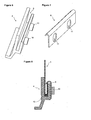
- Figure 2 is the partial sectional view of the locking element, the base and the body joined together in an embodiment of the present invention.
- Figure 3 - is the partial sectional view of the locking element in an embodiment of the present invention.
- Figure 4 - is the partial sectional view of the locking element, the base and the body joined together in another embodiment of the present invention.
- Figure 5 - is the partial sectional view of the locking element in another embodiment of the present invention.
- Figure 6 - is the partial perspective view of the side of the base in yet another embodiment of the present invention.
- Figure 7 - is the partial sectional view of the locking element in yet another embodiment of the present invention.
- Figure 8 - is the partial sectional view of the locking element, the base and the body joined together in another embodiment of the present invention.
- Figure 9 - is the partial perspective view of a body comprising a "zigzag" shaped projection.
- Figure 10 - is the partial sectional view of the locking element, the base and the body joined together in yet another embodiment of the present invention.
- Figure 11 - is the partial perspective view of the side of a body in another embodiment of the present invention.
- Figure 12 - is the partial perspective view of the side of the base in another embodiment of the present invention.
- Figure 13 - is the partial sectional view of the locking element, the base and the body joined together in yet another embodiment of the present invention.
- the dishwasher (1) of the present invention comprises washing tank (2) having a body (3), produced of metal, shaped like a box with the front and the bottom open, and having a base (4) produced of polymer material, e.g. plastic, joined together with the body (3) by emplacing under the body (3) ( Figure 1 ).
- the body (3) comprises a projection (7) formed by bending its side seated on the base (4).
- the base (4) comprises a housing (5) into which the projection (7) is fitted and an opening (6) through which the projection (7) is fitted into the housing (5).
- the dishwasher (1) comprises a locking element (8), produced separately from the base (4) and the body (3), one side of which is fixed to the base (4) and the other side extends from outside towards the inside of the housing (5) so as to block it's opening (6) partially" preventing the detachment of the projection (7) from the housing (5) by exerting force on the projection (7) and providing the body (3) and the base (4) to be clamped to each other.
- the dishwasher (1) comprises one or more leak-proofing elements (13) situated between the projection (7) and the housing (5) wherein the projection (7) is seated.
- the projection (6) is inserted into the housing (5) such that the leak-proofing element (13) is preferably disposed between itself and the housing (5).
- the entire surface of the projection (7) bears on the side walls of the housing (5).
- the locking element (8) is fixed to the base (4) so as to block the opening (6) of the housing (5) partially.
- the projection (7) bears on the locking element (8). Accordingly, the detachment of the projection (7) from the housing (5) it's disposed in and hence the detachment of the body (3) from the base (4) is prevented.
- the sides of the locking element (8) are being shaped via various shaping processes - cutting, twisting, bending, piercing and etc. - in such a way that not only it extends towards the housing (5) but also to ease its attachment to the base (4).
- the locking element (8) is preferably bent such that its two opposite sides faces each other.
- the locking element (8) is mounted on the base (4) via various fastening methods after it is twisted or bent such that one of its ends extends towards the housing (5) and exerts a force on the projection (7) and the other end eases the mounting ( Figure 2, Figure 3 , Figure 4 and Figure 5 ).
- the sides of the locking element (8) is shaped so that the locking element (8) is in "C", "U” or "L” form.
- the locking element (8) comprises protrusions (9) of various shapes and numbers on it, extending up to the bending point of the projection (7) fitted in the housing (5) and exerts force on this point.
- the locking element (8) is mounted on the base (4) such that it exerts force on the projection (7) that is fitted in the housing (5).
- the locking element (8) bears on the bending point of the projection (7) in the housing (5) and the protrusions (9) provide the projection (7) to be squeezed in between the side walls of the housing (5).
- the body (3) is prevented from moving in the vertical direction, and by means of the protrusions (9) the body is prevented from moving in the horizontal direction, providing the base (4) and the body (3) to be entirely clamped to each other ( Figure 4 and Figure 5 ).
- the projection (7) inserted into the housing (5) is formed by bending more than once in "zigzag” or "S" shape such that it exerts force at least from two points to both of the side walls of the housing (5).
- the width of the projection (7) almost equals to the width of the housing (5).
- the bending points exert force on the side walls of the housing (5) by contacting the side walls at intervals, providing the squeezing of the projection (7) in the housing (5) and the clamping of the base and the body (4 and 3) to each other in a leak-proof manner.
- the locking element (8) exerts force on the part of the projection (7) closest to the opening (6) of the housing (5) ( Figure 9 and Figure 10 ).
- cut outs (12) are provided at certain intervals on its bended portions.
- the base (4) comprises one or more pins (10) that provide fixing of the locking element (8) to the base (4) ( Figure 6 ).
- the locking element (8) comprises one or more holes (11) into which the pins (10) are fitted ( Figure 7 ).
- the locking element (8) is mounted on the base (4) such that the pins (10) are inserted in the holes (11) and the locking element (8) is squeezed in between the base (4) and the pin (10) by implementing various methods (applying heat, pressure etc.) providing it to be fixed on the base (4) ( Figure 8 ).
- the housing (5) is positioned on the base (4) such that its orifice (6) faces downward. Accordingly, the preferably "U" shaped projection (7) enters into the housing (5) and the base (4) is partially supported by this projection (7).
- a locking element (8) fixed to the base (4) such that the orifice (6) of the housing (5) is partially covered after the projection (7) is fitted in the housing (5), prevents the detachment of the projection (7) from the housing (5).
- a screw is used as the locking element (8).
- the fixing in this embodiment can also be done at the point where the base (4) and the body (3) contact each other ( Figure 4, Figure 5 and Figure 6 ).
- the body (3) is provided to clamp with the base (4) in a leak-proof manner.
Landscapes
- Connection Of Plates (AREA)
Description
- The present invention relates to a dishwasher comprising a washing tank composed by joining together a plastic base and a metal body.
- The washing tanks of dishwashers are usually produced as a single piece from metal or plastic material.
- However, in state of the art, there are also dishwashers comprising washing tanks composed of a plastic or plastic derivative base which can be easily processed and is cheaper, and a body produced of metal that are joined together. Producing the base of plastics provides easier shaping of the base. Producing the body of metal is preferred in view of giving the user an impression of hygiene.
- Composing the washing tank being of two separate pieces, being plastic and metal, creates various problems in joining these two parts together.
- In the state-of-the-art European Patent no.
EP0452287 , a dishwasher comprising a washing tank composed of two parts is described. The plastic base and the metal body forming the washing tank are joined together by screw joints. - In this embodiment where the base and the body are joined together by screws, screwing is performed with certain spacing in between, moreover the forces applied on each screw can be different. This results in not being able to join the base and the body, so as to provide sealing.
- In the state-of-the-art United States Patent Application no.
US2005/0017609 , the washing tank of a dishwasher is composed of two pieces, a base and a body. In the said application, the use of a plastic material having an adhesive feature in joining these two pieces is explained. - The object of the present invention is the realization of a dishwasher comprising a washing tank produced such that the plastic base and the metal body are joined in a non-detachable and leak-proof manner.
- The dishwasher realized in order to fulfill the objectives of the present invention, explicated in the first claim and other dependent claims, comprises a washing tank composed by joining together a plastic base and a metal body.
- The dishwasher comprises a body having a projection formed by bending its side in preferably a "U" shape, a base having a housing into which the projection is seated and a locking element that partially blocks the opening of this housing.
- In another embodiment of the present invention, movement of the body in the upward direction is restrained by a locking element, which, is fastened to the housing that the projection enters via various methods, extends towards the opening of the housing such that it partially blocks the opening and is produced separately from the housing. In this embodiment, different from the point contact present in the joining with screw, the housing and the projection contacts each other along a larger surface and thus the joining of the base and the body together so as to provide better sealing is provided.
- In an embodiment of the present invention, the locking element can be produced of a material different from the material used in producing the base.
- In another embodiment of the present invention, the projection is formed by bending in an "S" or "zigzag" shape. An effective leak-proofing is maintained by the side being bended in this shape, by means of contacting the side walls of the housing along more than one line.
- In another embodiment of the present invention both ends of the locking element is bent so as to face each other. One of the bent ends of the locking element is fixed to the base, whereas the other end extends towards the opening of the housing and thus the locking element is attached to the base.
- In another embodiment of the present invention, the dishwasher comprises a housing formed on the base such that its opening faces downward. The projection inserted into the housing partially supports the base. The screw shaped locking element, fixed to the base such that the opening of the housing is partially blocked after the projection is seated in the housing, prevents the detachment of the projection from the housing.
- By way of the present invention, the water in the washing tank composed by joining two pieces together is prevented from leaking out of the joint region wherein the base and the body are clamped together.
- The dishwashers realized in order to fulfill the objectives of the present invention is illustrated in the attached figures, where:
-
Figure 1 - is the schematic view of a dishwasher. -
Figure 2 -is the partial sectional view of the locking element, the base and the body joined together in an embodiment of the present invention. -
Figure 3 - is the partial sectional view of the locking element in an embodiment of the present invention. -
Figure 4 - is the partial sectional view of the locking element, the base and the body joined together in another embodiment of the present invention. -
Figure 5 - is the partial sectional view of the locking element in another embodiment of the present invention. -
Figure 6 - is the partial perspective view of the side of the base in yet another embodiment of the present invention. -
Figure 7 - is the partial sectional view of the locking element in yet another embodiment of the present invention. -
Figure 8 - is the partial sectional view of the locking element, the base and the body joined together in another embodiment of the present invention. -
Figure 9 - is the partial perspective view of a body comprising a "zigzag" shaped projection. -
Figure 10 - is the partial sectional view of the locking element, the base and the body joined together in yet another embodiment of the present invention. -
Figure 11 - is the partial perspective view of the side of a body in another embodiment of the present invention. -
Figure 12 - is the partial perspective view of the side of the base in another embodiment of the present invention. -
Figure 13 - is the partial sectional view of the locking element, the base and the body joined together in yet another embodiment of the present invention. - The elements shown in figures are numbered as follows:
- 1.
- Dishwasher
- 2.
- Washing tank
- 3.
- Body
- 4.
- Base
- 5.
- Housing
- 6.
- Opening
- 7.
- Projection
- 8.
- Locking element
- 9.
- Protrusion
- 10.
- Pin
- 11.
- Hole
- 12.
- Cut-out
- 13.
- Leak-proofing element
- The dishwasher (1) of the present invention comprises washing tank (2) having a body (3), produced of metal, shaped like a box with the front and the bottom open, and having a base (4) produced of polymer material, e.g. plastic, joined together with the body (3) by emplacing under the body (3) (
Figure 1 ). - The body (3) comprises a projection (7) formed by bending its side seated on the base (4).
- The base (4) comprises a housing (5) into which the projection (7) is fitted and an opening (6) through which the projection (7) is fitted into the housing (5).
- The dishwasher (1) comprises a locking element (8), produced separately from the base (4) and the body (3), one side of which is fixed to the base (4) and the other side extends from outside towards the inside of the housing (5) so as to block it's opening (6) partially" preventing the detachment of the projection (7) from the housing (5) by exerting force on the projection (7) and providing the body (3) and the base (4) to be clamped to each other.
- The dishwasher (1) comprises one or more leak-proofing elements (13) situated between the projection (7) and the housing (5) wherein the projection (7) is seated.
- When the body (3) is desired to be joined with the base (4), the projection (6) is inserted into the housing (5) such that the leak-proofing element (13) is preferably disposed between itself and the housing (5). The entire surface of the projection (7) bears on the side walls of the housing (5). In this embodiment, after the projection (7) is disposed in the housing (5) the locking element (8) is fixed to the base (4) so as to block the opening (6) of the housing (5) partially. When a force is exerted on the body (3), the projection (7) bears on the locking element (8). Accordingly, the detachment of the projection (7) from the housing (5) it's disposed in and hence the detachment of the body (3) from the base (4) is prevented.
- In another embodiment of the present invention, the sides of the locking element (8) are being shaped via various shaping processes - cutting, twisting, bending, piercing and etc. - in such a way that not only it extends towards the housing (5) but also to ease its attachment to the base (4). In this embodiment the locking element (8) is preferably bent such that its two opposite sides faces each other. Thus the locking element (8) is mounted on the base (4) via various fastening methods after it is twisted or bent such that one of its ends extends towards the housing (5) and exerts a force on the projection (7) and the other end eases the mounting (
Figure 2, Figure 3 ,Figure 4 and Figure 5 ). - In another embodiment of the present invention, the sides of the locking element (8) is shaped so that the locking element (8) is in "C", "U" or "L" form.
- In yet another embodiment of the present invention, the locking element (8) comprises protrusions (9) of various shapes and numbers on it, extending up to the bending point of the projection (7) fitted in the housing (5) and exerts force on this point. The locking element (8) is mounted on the base (4) such that it exerts force on the projection (7) that is fitted in the housing (5). When the locking element (8) is mounted on the base (4) like this, the locking element (8) bears on the bending point of the projection (7) in the housing (5) and the protrusions (9) provide the projection (7) to be squeezed in between the side walls of the housing (5). In this embodiment, by the locking element (8) extending up to and bearing on the bending point of the projection (7), the body (3) is prevented from moving in the vertical direction, and by means of the protrusions (9) the body is prevented from moving in the horizontal direction, providing the base (4) and the body (3) to be entirely clamped to each other (
Figure 4 and Figure 5 ). - In another embodiment of the present invention, the projection (7) inserted into the housing (5) is formed by bending more than once in "zigzag" or "S" shape such that it exerts force at least from two points to both of the side walls of the housing (5). The width of the projection (7) almost equals to the width of the housing (5). The bending points exert force on the side walls of the housing (5) by contacting the side walls at intervals, providing the squeezing of the projection (7) in the housing (5) and the clamping of the base and the body (4 and 3) to each other in a leak-proof manner. In this embodiment of the present invention, the locking element (8) exerts force on the part of the projection (7) closest to the opening (6) of the housing (5) (
Figure 9 and Figure 10 ). - In another embodiment of the present invention, in order to form the portion of the locking piece (8) extending towards the opening (6) of the housing (5) more easily, cut outs (12) are provided at certain intervals on its bended portions.
- In another embodiment of the present invention, the base (4) comprises one or more pins (10) that provide fixing of the locking element (8) to the base (4) (
Figure 6 ). In this embodiment, the locking element (8) comprises one or more holes (11) into which the pins (10) are fitted (Figure 7 ). The locking element (8) is mounted on the base (4) such that the pins (10) are inserted in the holes (11) and the locking element (8) is squeezed in between the base (4) and the pin (10) by implementing various methods (applying heat, pressure etc.) providing it to be fixed on the base (4) (Figure 8 ). - In another embodiment of the present invention the housing (5) is positioned on the base (4) such that its orifice (6) faces downward. Accordingly, the preferably "U" shaped projection (7) enters into the housing (5) and the base (4) is partially supported by this projection (7). A locking element (8), fixed to the base (4) such that the orifice (6) of the housing (5) is partially covered after the projection (7) is fitted in the housing (5), prevents the detachment of the projection (7) from the housing (5). In this embodiment, a screw is used as the locking element (8). However, the fixing in this embodiment can also be done at the point where the base (4) and the body (3) contact each other (
Figure 4, Figure 5 andFigure 6 ). - By the present invention, the body (3) is provided to clamp with the base (4) in a leak-proof manner.
Claims (8)
- A dishwasher (1) comprising a washing tank (2) composed of a body (3), produced of metal, shaped like a box with the front and the bottom open, having a projection (7) formed by bending its side, and a base (4) produced of polymer material, having a housing (5), inside which the projection (7) is fitted and an opening (6) through which the projection (7) is emplaced in the housing (5) and characterized by a locking element (8) produced separately from the base (4) and the body (3), one side of the locking element (8) is fixed to the base (4) and the other side extends into the housing (5), partially blocking the opening (6), preventing the detachment of the projection (7) from the housing (5) by exerting force on the projection (7) emplaced in the housing (5) and providing the body (3) to be clamped to the base (4).
- A dishwasher (1) as in Claim 1, characterized by a body (3) comprising a projection (7), extending into the housing (5), formed by bending more than once in "zigzag" or "S" shape such that it exerts force from at least two points to both sides of the housing (5).
- A dishwasher (1) as in Claim 1, characterized by a locking element (8) whose sides are shaped via various shaping processes, not only to extend towards the inside of the housing (5) but also to ease its mounting to the base (4).
- A dishwasher (1) as in Claim 3, characterized by a locking element (8) that is mounted on the base (4) after it is bent such that its two opposite sides faces each other, one of its ends extends towards the inside of the housing (5) and the other end eases its mounting on the base (4).
- A dishwasher (1) as in Claim 1, characterized by a locking element (8) that comprises cut outs (12) that are provided at certain intervals on its bended portions in order to form the portion of the locking piece (8) extending towards the opening (6) of the housing (5) more easily.
- A dishwasher (1) as in any one of the above claims, characterized by a base (4) having a housing (5) on it, which is positioned such that its opening (6) faces downwards.
- A dishwasher (1) as in Claim 1, characterized by a locking element (8) having protrusions (9) on it, of various shapes and numbers, that extends up to the bending point of the projection (7) fitted in the housing (5), exerting force on this point.
- A dishwasher (1) as in any one of the above claim, characterized by a base (4) having one or more pins (10) providing to fix the locking element (8) and a locking element (8) having one or more holes (11) into which the pins (10) are inserted.
Applications Claiming Priority (2)
| Application Number | Priority Date | Filing Date | Title |
|---|---|---|---|
| TR200504874 | 2005-12-15 | ||
| PCT/EP2006/069337 WO2007068634A1 (en) | 2005-12-15 | 2006-12-05 | A dishwasher |
Publications (2)
| Publication Number | Publication Date |
|---|---|
| EP1959814A1 EP1959814A1 (en) | 2008-08-27 |
| EP1959814B1 true EP1959814B1 (en) | 2013-01-23 |
Family
ID=37745981
Family Applications (1)
| Application Number | Title | Priority Date | Filing Date |
|---|---|---|---|
| EP06830383A Not-in-force EP1959814B1 (en) | 2005-12-15 | 2006-12-05 | A dishwasher |
Country Status (2)
| Country | Link |
|---|---|
| EP (1) | EP1959814B1 (en) |
| WO (1) | WO2007068634A1 (en) |
Families Citing this family (4)
| Publication number | Priority date | Publication date | Assignee | Title |
|---|---|---|---|---|
| DE102007030064A1 (en) * | 2007-06-29 | 2009-01-02 | BSH Bosch und Siemens Hausgeräte GmbH | Platform for a dishwasher |
| DE102007031478A1 (en) | 2007-07-06 | 2009-01-08 | BSH Bosch und Siemens Hausgeräte GmbH | System kit for dishwasher inner container |
| US9155443B2 (en) | 2011-09-21 | 2015-10-13 | Whirlpool Corporation | Dishwasher with multi-piece tub |
| US20250369467A1 (en) * | 2024-05-29 | 2025-12-04 | GM Global Technology Operations LLC | Automotive flanged interface attachment |
Family Cites Families (6)
| Publication number | Priority date | Publication date | Assignee | Title |
|---|---|---|---|---|
| GB963875A (en) * | 1963-06-11 | 1964-07-15 | Ass Elect Ind | Improvements relating to washing machines |
| DE8500663U1 (en) * | 1985-01-12 | 1986-05-07 | Licentia Patent-Verwaltungs-Gmbh, 6000 Frankfurt | Dishwasher with a drain pan on the bottom of the washing container |
| DE3636437A1 (en) * | 1986-10-25 | 1988-05-05 | Licentia Gmbh | Dishwasher |
| EP0541849A1 (en) * | 1991-11-14 | 1993-05-19 | Electrolux AG | Connection of surfaces, and washing and/or drying machine |
| IT1305665B1 (en) * | 1998-03-02 | 2001-05-15 | Electrolux Zanussi Elettrodome | WASHING MACHINE WITH A PERFECT BUILDING FURNITURE |
| DE10156423A1 (en) * | 2001-11-16 | 2003-06-05 | Bsh Bosch Siemens Hausgeraete | Two-part washing container for a dishwasher and method for producing a two-part washing container for a dishwasher |
-
2006
- 2006-12-05 WO PCT/EP2006/069337 patent/WO2007068634A1/en not_active Ceased
- 2006-12-05 EP EP06830383A patent/EP1959814B1/en not_active Not-in-force
Also Published As
| Publication number | Publication date |
|---|---|
| EP1959814A1 (en) | 2008-08-27 |
| WO2007068634A1 (en) | 2007-06-21 |
Similar Documents
| Publication | Publication Date | Title |
|---|---|---|
| US9005370B2 (en) | Water-conducting household appliance having a treatment container assembled from at least two components | |
| EP2162047A2 (en) | Dishwasher platform | |
| WO2008080933A1 (en) | A dishwasher | |
| EP1835065B1 (en) | Tub with plate-shaped heating device | |
| KR20190063351A (en) | A frame fixing device formed on a corner connector for a frame | |
| WO2007068634A1 (en) | A dishwasher | |
| EP1956960B1 (en) | A dishwasher | |
| KR100750806B1 (en) | Security window | |
| CN220988729U (en) | Liner and dish washer | |
| CN214774097U (en) | Mounting structure of injection molding piece on steering wheel | |
| CN101208467B (en) | Heater apparatus for washing machine | |
| KR200154212Y1 (en) | Wall fixing apparatus of wall fixing device | |
| KR200207400Y1 (en) | Handle attachment structure of cookware | |
| PT1747746E (en) | Device for fastening a connecting member to a handle of a cooking vessel | |
| KR200221712Y1 (en) | Frame fixture | |
| JP3776359B2 (en) | Rice cooker lid reinforcement structure | |
| KR200369340Y1 (en) | Plant fruit type brooch | |
| KR200197867Y1 (en) | Joining block structure of fire extinguisher | |
| CN116919292B (en) | Connection structure between cavity and base of dishwasher and dishwasher | |
| CN216675442U (en) | Pot body subassembly and electric saucepan | |
| CN222217711U (en) | Food processor | |
| WO2007065875A1 (en) | A dishwasher | |
| CN111374623A (en) | Handle, bowl basket with handle and dish washing machine | |
| CN210433444U (en) | Shell of dish-washing machine and dish-washing machine | |
| KR0126119Y1 (en) | Mascot of a washing machine bonding structure |
Legal Events
| Date | Code | Title | Description |
|---|---|---|---|
| PUAI | Public reference made under article 153(3) epc to a published international application that has entered the european phase |
Free format text: ORIGINAL CODE: 0009012 |
|
| 17P | Request for examination filed |
Effective date: 20080514 |
|
| AK | Designated contracting states |
Kind code of ref document: A1 Designated state(s): AT BE BG CH CY CZ DE DK EE ES FI FR GB GR HU IE IS IT LI LT LU LV MC NL PL PT RO SE SI SK TR |
|
| 17Q | First examination report despatched |
Effective date: 20111011 |
|
| DAX | Request for extension of the european patent (deleted) | ||
| GRAP | Despatch of communication of intention to grant a patent |
Free format text: ORIGINAL CODE: EPIDOSNIGR1 |
|
| GRAS | Grant fee paid |
Free format text: ORIGINAL CODE: EPIDOSNIGR3 |
|
| GRAA | (expected) grant |
Free format text: ORIGINAL CODE: 0009210 |
|
| AK | Designated contracting states |
Kind code of ref document: B1 Designated state(s): AT BE BG CH CY CZ DE DK EE ES FI FR GB GR HU IE IS IT LI LT LU LV MC NL PL PT RO SE SI SK TR |
|
| REG | Reference to a national code |
Ref country code: GB Ref legal event code: FG4D |
|
| REG | Reference to a national code |
Ref country code: CH Ref legal event code: EP |
|
| REG | Reference to a national code |
Ref country code: CH Ref legal event code: EP Ref country code: AT Ref legal event code: REF Ref document number: 594507 Country of ref document: AT Kind code of ref document: T Effective date: 20130215 |
|
| REG | Reference to a national code |
Ref country code: IE Ref legal event code: FG4D |
|
| REG | Reference to a national code |
Ref country code: DE Ref legal event code: R096 Ref document number: 602006034406 Country of ref document: DE Effective date: 20130321 |
|
| REG | Reference to a national code |
Ref country code: AT Ref legal event code: MK05 Ref document number: 594507 Country of ref document: AT Kind code of ref document: T Effective date: 20130123 |
|
| REG | Reference to a national code |
Ref country code: LT Ref legal event code: MG4D |
|
| REG | Reference to a national code |
Ref country code: NL Ref legal event code: VDEP Effective date: 20130123 |
|
| PG25 | Lapsed in a contracting state [announced via postgrant information from national office to epo] |
Ref country code: LT Free format text: LAPSE BECAUSE OF FAILURE TO SUBMIT A TRANSLATION OF THE DESCRIPTION OR TO PAY THE FEE WITHIN THE PRESCRIBED TIME-LIMIT Effective date: 20130123 Ref country code: SE Free format text: LAPSE BECAUSE OF FAILURE TO SUBMIT A TRANSLATION OF THE DESCRIPTION OR TO PAY THE FEE WITHIN THE PRESCRIBED TIME-LIMIT Effective date: 20130123 Ref country code: BG Free format text: LAPSE BECAUSE OF FAILURE TO SUBMIT A TRANSLATION OF THE DESCRIPTION OR TO PAY THE FEE WITHIN THE PRESCRIBED TIME-LIMIT Effective date: 20130423 Ref country code: AT Free format text: LAPSE BECAUSE OF FAILURE TO SUBMIT A TRANSLATION OF THE DESCRIPTION OR TO PAY THE FEE WITHIN THE PRESCRIBED TIME-LIMIT Effective date: 20130123 Ref country code: IS Free format text: LAPSE BECAUSE OF FAILURE TO SUBMIT A TRANSLATION OF THE DESCRIPTION OR TO PAY THE FEE WITHIN THE PRESCRIBED TIME-LIMIT Effective date: 20130523 Ref country code: CY Free format text: LAPSE BECAUSE OF FAILURE TO SUBMIT A TRANSLATION OF THE DESCRIPTION OR TO PAY THE FEE WITHIN THE PRESCRIBED TIME-LIMIT Effective date: 20130123 Ref country code: BE Free format text: LAPSE BECAUSE OF FAILURE TO SUBMIT A TRANSLATION OF THE DESCRIPTION OR TO PAY THE FEE WITHIN THE PRESCRIBED TIME-LIMIT Effective date: 20130123 Ref country code: ES Free format text: LAPSE BECAUSE OF FAILURE TO SUBMIT A TRANSLATION OF THE DESCRIPTION OR TO PAY THE FEE WITHIN THE PRESCRIBED TIME-LIMIT Effective date: 20130504 |
|
| PG25 | Lapsed in a contracting state [announced via postgrant information from national office to epo] |
Ref country code: SI Free format text: LAPSE BECAUSE OF FAILURE TO SUBMIT A TRANSLATION OF THE DESCRIPTION OR TO PAY THE FEE WITHIN THE PRESCRIBED TIME-LIMIT Effective date: 20130123 Ref country code: NL Free format text: LAPSE BECAUSE OF FAILURE TO SUBMIT A TRANSLATION OF THE DESCRIPTION OR TO PAY THE FEE WITHIN THE PRESCRIBED TIME-LIMIT Effective date: 20130123 Ref country code: LV Free format text: LAPSE BECAUSE OF FAILURE TO SUBMIT A TRANSLATION OF THE DESCRIPTION OR TO PAY THE FEE WITHIN THE PRESCRIBED TIME-LIMIT Effective date: 20130123 Ref country code: PT Free format text: LAPSE BECAUSE OF FAILURE TO SUBMIT A TRANSLATION OF THE DESCRIPTION OR TO PAY THE FEE WITHIN THE PRESCRIBED TIME-LIMIT Effective date: 20130523 Ref country code: GR Free format text: LAPSE BECAUSE OF FAILURE TO SUBMIT A TRANSLATION OF THE DESCRIPTION OR TO PAY THE FEE WITHIN THE PRESCRIBED TIME-LIMIT Effective date: 20130424 Ref country code: FI Free format text: LAPSE BECAUSE OF FAILURE TO SUBMIT A TRANSLATION OF THE DESCRIPTION OR TO PAY THE FEE WITHIN THE PRESCRIBED TIME-LIMIT Effective date: 20130123 Ref country code: PL Free format text: LAPSE BECAUSE OF FAILURE TO SUBMIT A TRANSLATION OF THE DESCRIPTION OR TO PAY THE FEE WITHIN THE PRESCRIBED TIME-LIMIT Effective date: 20130123 |
|
| PG25 | Lapsed in a contracting state [announced via postgrant information from national office to epo] |
Ref country code: EE Free format text: LAPSE BECAUSE OF FAILURE TO SUBMIT A TRANSLATION OF THE DESCRIPTION OR TO PAY THE FEE WITHIN THE PRESCRIBED TIME-LIMIT Effective date: 20130123 Ref country code: RO Free format text: LAPSE BECAUSE OF FAILURE TO SUBMIT A TRANSLATION OF THE DESCRIPTION OR TO PAY THE FEE WITHIN THE PRESCRIBED TIME-LIMIT Effective date: 20130123 Ref country code: DK Free format text: LAPSE BECAUSE OF FAILURE TO SUBMIT A TRANSLATION OF THE DESCRIPTION OR TO PAY THE FEE WITHIN THE PRESCRIBED TIME-LIMIT Effective date: 20130123 Ref country code: CZ Free format text: LAPSE BECAUSE OF FAILURE TO SUBMIT A TRANSLATION OF THE DESCRIPTION OR TO PAY THE FEE WITHIN THE PRESCRIBED TIME-LIMIT Effective date: 20130123 Ref country code: SK Free format text: LAPSE BECAUSE OF FAILURE TO SUBMIT A TRANSLATION OF THE DESCRIPTION OR TO PAY THE FEE WITHIN THE PRESCRIBED TIME-LIMIT Effective date: 20130123 |
|
| PLBE | No opposition filed within time limit |
Free format text: ORIGINAL CODE: 0009261 |
|
| STAA | Information on the status of an ep patent application or granted ep patent |
Free format text: STATUS: NO OPPOSITION FILED WITHIN TIME LIMIT |
|
| PG25 | Lapsed in a contracting state [announced via postgrant information from national office to epo] |
Ref country code: IT Free format text: LAPSE BECAUSE OF FAILURE TO SUBMIT A TRANSLATION OF THE DESCRIPTION OR TO PAY THE FEE WITHIN THE PRESCRIBED TIME-LIMIT Effective date: 20130123 |
|
| 26N | No opposition filed |
Effective date: 20131024 |
|
| REG | Reference to a national code |
Ref country code: DE Ref legal event code: R097 Ref document number: 602006034406 Country of ref document: DE Effective date: 20131024 |
|
| PG25 | Lapsed in a contracting state [announced via postgrant information from national office to epo] |
Ref country code: MC Free format text: LAPSE BECAUSE OF FAILURE TO SUBMIT A TRANSLATION OF THE DESCRIPTION OR TO PAY THE FEE WITHIN THE PRESCRIBED TIME-LIMIT Effective date: 20130123 |
|
| REG | Reference to a national code |
Ref country code: CH Ref legal event code: PL |
|
| PG25 | Lapsed in a contracting state [announced via postgrant information from national office to epo] |
Ref country code: LU Free format text: LAPSE BECAUSE OF FAILURE TO SUBMIT A TRANSLATION OF THE DESCRIPTION OR TO PAY THE FEE WITHIN THE PRESCRIBED TIME-LIMIT Effective date: 20131205 |
|
| REG | Reference to a national code |
Ref country code: IE Ref legal event code: MM4A |
|
| PG25 | Lapsed in a contracting state [announced via postgrant information from national office to epo] |
Ref country code: IE Free format text: LAPSE BECAUSE OF NON-PAYMENT OF DUE FEES Effective date: 20131205 Ref country code: CH Free format text: LAPSE BECAUSE OF NON-PAYMENT OF DUE FEES Effective date: 20131231 Ref country code: LI Free format text: LAPSE BECAUSE OF NON-PAYMENT OF DUE FEES Effective date: 20131231 |
|
| PGFP | Annual fee paid to national office [announced via postgrant information from national office to epo] |
Ref country code: TR Payment date: 20141021 Year of fee payment: 9 |
|
| PG25 | Lapsed in a contracting state [announced via postgrant information from national office to epo] |
Ref country code: HU Free format text: LAPSE BECAUSE OF FAILURE TO SUBMIT A TRANSLATION OF THE DESCRIPTION OR TO PAY THE FEE WITHIN THE PRESCRIBED TIME-LIMIT; INVALID AB INITIO Effective date: 20061205 |
|
| REG | Reference to a national code |
Ref country code: FR Ref legal event code: PLFP Year of fee payment: 10 |
|
| REG | Reference to a national code |
Ref country code: FR Ref legal event code: PLFP Year of fee payment: 11 |
|
| PGFP | Annual fee paid to national office [announced via postgrant information from national office to epo] |
Ref country code: GB Payment date: 20161222 Year of fee payment: 11 Ref country code: DE Payment date: 20161213 Year of fee payment: 11 |
|
| PGFP | Annual fee paid to national office [announced via postgrant information from national office to epo] |
Ref country code: FR Payment date: 20161222 Year of fee payment: 11 |
|
| REG | Reference to a national code |
Ref country code: DE Ref legal event code: R119 Ref document number: 602006034406 Country of ref document: DE |
|
| GBPC | Gb: european patent ceased through non-payment of renewal fee |
Effective date: 20171205 |
|
| REG | Reference to a national code |
Ref country code: FR Ref legal event code: ST Effective date: 20180831 |
|
| PG25 | Lapsed in a contracting state [announced via postgrant information from national office to epo] |
Ref country code: DE Free format text: LAPSE BECAUSE OF NON-PAYMENT OF DUE FEES Effective date: 20180703 Ref country code: FR Free format text: LAPSE BECAUSE OF NON-PAYMENT OF DUE FEES Effective date: 20180102 |
|
| PG25 | Lapsed in a contracting state [announced via postgrant information from national office to epo] |
Ref country code: GB Free format text: LAPSE BECAUSE OF NON-PAYMENT OF DUE FEES Effective date: 20171205 |
|
| PG25 | Lapsed in a contracting state [announced via postgrant information from national office to epo] |
Ref country code: TR Free format text: LAPSE BECAUSE OF NON-PAYMENT OF DUE FEES Effective date: 20171205 |