EP1959612B1 - Radio coexistence mechanism for variable data rate radio links - Google Patents
Radio coexistence mechanism for variable data rate radio links Download PDFInfo
- Publication number
- EP1959612B1 EP1959612B1 EP07003400A EP07003400A EP1959612B1 EP 1959612 B1 EP1959612 B1 EP 1959612B1 EP 07003400 A EP07003400 A EP 07003400A EP 07003400 A EP07003400 A EP 07003400A EP 1959612 B1 EP1959612 B1 EP 1959612B1
- Authority
- EP
- European Patent Office
- Prior art keywords
- radio
- link
- coexistence
- transmitter
- monitor
- Prior art date
- Legal status (The legal status is an assumption and is not a legal conclusion. Google has not performed a legal analysis and makes no representation as to the accuracy of the status listed.)
- Active
Links
Images


Classifications
-
- H—ELECTRICITY
- H04—ELECTRIC COMMUNICATION TECHNIQUE
- H04W—WIRELESS COMMUNICATION NETWORKS
- H04W72/00—Local resource management
- H04W72/02—Selection of wireless resources by user or terminal
-
- H—ELECTRICITY
- H04—ELECTRIC COMMUNICATION TECHNIQUE
- H04L—TRANSMISSION OF DIGITAL INFORMATION, e.g. TELEGRAPHIC COMMUNICATION
- H04L1/00—Arrangements for detecting or preventing errors in the information received
- H04L1/0001—Systems modifying transmission characteristics according to link quality, e.g. power backoff
- H04L1/0002—Systems modifying transmission characteristics according to link quality, e.g. power backoff by adapting the transmission rate
- H04L1/0003—Systems modifying transmission characteristics according to link quality, e.g. power backoff by adapting the transmission rate by switching between different modulation schemes
-
- H—ELECTRICITY
- H04—ELECTRIC COMMUNICATION TECHNIQUE
- H04L—TRANSMISSION OF DIGITAL INFORMATION, e.g. TELEGRAPHIC COMMUNICATION
- H04L1/00—Arrangements for detecting or preventing errors in the information received
- H04L1/0001—Systems modifying transmission characteristics according to link quality, e.g. power backoff
- H04L1/0015—Systems modifying transmission characteristics according to link quality, e.g. power backoff characterised by the adaptation strategy
- H04L1/0017—Systems modifying transmission characteristics according to link quality, e.g. power backoff characterised by the adaptation strategy where the mode-switching is based on Quality of Service requirement
- H04L1/0018—Systems modifying transmission characteristics according to link quality, e.g. power backoff characterised by the adaptation strategy where the mode-switching is based on Quality of Service requirement based on latency requirement
-
- H—ELECTRICITY
- H04—ELECTRIC COMMUNICATION TECHNIQUE
- H04L—TRANSMISSION OF DIGITAL INFORMATION, e.g. TELEGRAPHIC COMMUNICATION
- H04L1/00—Arrangements for detecting or preventing errors in the information received
- H04L1/12—Arrangements for detecting or preventing errors in the information received by using return channel
- H04L1/16—Arrangements for detecting or preventing errors in the information received by using return channel in which the return channel carries supervisory signals, e.g. repetition request signals
- H04L1/18—Automatic repetition systems, e.g. Van Duuren systems
- H04L1/1867—Arrangements specially adapted for the transmitter end
-
- H—ELECTRICITY
- H04—ELECTRIC COMMUNICATION TECHNIQUE
- H04W—WIRELESS COMMUNICATION NETWORKS
- H04W24/00—Supervisory, monitoring or testing arrangements
-
- H—ELECTRICITY
- H04—ELECTRIC COMMUNICATION TECHNIQUE
- H04W—WIRELESS COMMUNICATION NETWORKS
- H04W28/00—Network traffic management; Network resource management
- H04W28/16—Central resource management; Negotiation of resources or communication parameters, e.g. negotiating bandwidth or QoS [Quality of Service]
- H04W28/18—Negotiating wireless communication parameters
- H04W28/22—Negotiating communication rate
-
- H—ELECTRICITY
- H04—ELECTRIC COMMUNICATION TECHNIQUE
- H04W—WIRELESS COMMUNICATION NETWORKS
- H04W84/00—Network topologies
- H04W84/18—Self-organising networks, e.g. ad-hoc networks or sensor networks
-
- H—ELECTRICITY
- H04—ELECTRIC COMMUNICATION TECHNIQUE
- H04W—WIRELESS COMMUNICATION NETWORKS
- H04W88/00—Devices specially adapted for wireless communication networks, e.g. terminals, base stations or access point devices
- H04W88/02—Terminal devices
- H04W88/06—Terminal devices adapted for operation in multiple networks or having at least two operational modes, e.g. multi-mode terminals
Definitions
- This invention relates to devices having a radio transmitter with a coexistence controller, to corresponding methods of controlling transmissions, and to integrated circuits or software for carrying out such methods.
- radio links with automatically variable data rates. If the channel quality of the link changes owing to fading caused by movement or other changes in the air transmission path, this can be detected by a monitor and the data rate can be changed to suit or maximize the data transmissible over the link at the given time. It is also known to provide a coexistence control arranged to communicate with another radio transmitter suitable for part of another radio link, to control transmissions to enable both radio links to use potentially conflicting transmission frequencies.
- US 2002/0065907 A1 discloses a device having a radio transmitter for a first radio link and having a coexistence controller arranged to communicate with another radio transmitter for another radio link (i.e. BT-WLAN system hardware coexistence interface) and to control transmission to enable both radio links to use potentially conflicting transmission frequencies (i.e. WLAN/BT coexistence) the radio transmitter also having a link monitor arranged to monitor the first radio link (i.e. a rate fallback mechanism after a number of unsuccessful communications) according to an output from the coexistence controller (i.e. the rate fallback mechanism of the WLAN is disabled in a collocated WLAN/BT during periods in which the collocated BT system may transmit).
- the WLAN link controller is disabled when BT transmits.
- An object of the invention is to provide improved devices having a radio transmitter with a coexistence controller, to corresponding methods of controlling transmissions, and to integrated circuits or software for carrying out such methods.
- the invention provides: A device having a first radio transmitter for supporting a first radio link, the radio transmitter having a coexistence controller arranged to communicate with a second radio transmitter for supporting a second radio link, and to control transmission times of the first and second transmitter to enable both radio links to use potentially conflicting transmission frequencies as defined in claim 1.
- the transmitter and the other transmitter may be located within 1 meter of each other.
- Embodiments of the invention can involve any type of radio transmitter, any form of coexistence interface, and any form of link monitor. Embodiments can have any other additional features. Some additional features are described in more detail below. For example, the monitoring of an error rate of the link can be suspended in accordance with an output from the coexistence controller. Or the error rate can be determined by ignoring errors that occur during the a time determined by the output of the coexistence controller, i.e. during the time that the coexistence controller prevents one of the devices from transmitting. Another aspect of the invention can be summarized as a method of controlling radio transmissions as defined in claim 8.
- Some embodiments of the invention involve channel quality driven modulation change in multi-modulation wireless systems in case of frequency band sharing.
- Several wireless systems support variable data rates by varying their modulation scheme: for example recent Bluetooth standards (see http://www.bluetooth.org/spec/) supports 1 Mbps Physical rate (using GFSK modulation (Gaussian Frequency Shift Keying)), 2 Mbps Physical rate (using pi/4DQPSK modulation, (Differential Quadrature Phase Shift Keying)) and 3Mbps Physical rate (using 8-DPSK modulation, (Differential Phase Shift Keying)).
- GFSK modulation Gaussian Frequency Shift Keying
- 2 Mbps Physical rate using pi/4DQPSK modulation, (Differential Quadrature Phase Shift Keying)
- 3Mbps Physical rate using 8-DPSK modulation, (Differential Phase Shift Keying)
- IEEE 802.11b supports DSS (Distribution system Services) and CCK (Complemenatry Code Keying) modulations with physical rates from 1 to 11 Mbps and 802.11g (http:Hgrouper.ieee.org/groups/802/11/ ) is OFDM (Orthogonal Frequency Division Multiplexing) based with a physical rate up to 54 Mbps.
- a lower physical transmission rate implies mainly two things:
- Wireless systems supporting more than one modulation type can embed a monitor in the form of an algorithm capable of estimating the level of disturbance or interference present on the air interface. In some examples this can be done by making a count or some other assessment of the incorrectly received or not received packets and hence also a determination of needed retransmissions. The worse the quality of the air interface, the higher the bit error rate, the frame error rate, the symbol error rate or any other measure of the quality of received packets. Hence a monitor algorithm will assume that if any of these received signal quality measures are poor, that some adaptation is required. For example, the output of the monitor can be used by a controller to cause an automatic lowering of the data rate by changing the modulation if the algorithm deduces a drop in quality of the air link.
- Bluetooth this feature is called CQDDR (Channel Quality Driven Data Rate).
- Wireless systems like those defined by the Bluetooth and IEEE 802.11 standards share the same ISM (Industrial, Scentific and Medical) band situated at 2.4GHz.
- ISM Industrial, Scentific and Medical
- any two radio transmitter devices such as Bluetooth device and an IEEE 802.11 device, are placed within range, such as when they are incorporated in any way in the same product at a very close distance, perhaps a few centimeters apart (in the collocated scenario)
- the transmitters which may conflict may be located within 1 meter of each other.
- PTA Packet Traffic Arbitration
- An overall view including a coexistence mechanism in a collocated scenario is shown in fig. 1 .
- the coexistence bus could be implemented using any kind of communication link including a wired link, an optical link, another radio link or links etc.
- Each of the devices has their own largely independent radio links to other devices (not shown). What usually happens is that when one of the two devices has to do an RF transmission or has receiving activity considered vital for the application it requests the other device not to perform any RF activity (or at least no transmissions (TX)).
- the second device If the second device is already doing something it should stop it within a time T. This would cause on one or both links a certain number of missed packets and hence retransmissions forced by the coexistence mechanism. These retransmissions are forced by the coexistence mechanism and not directly by poorer air link quality. However, the monitor algorithm checking the link air quality will then observe an increased number of retransmissions, and deduce from this that the air quality has been degraded. The response to a degraded air interface is to change modulation, i.e. reduce data rate. The monitor algorithm will therefore cause a controller to change the modulation type and lower the physical rate of the transmissions. This change of modulation is actually unnecessary - the air interface can support the original modulation satisfactorily.
- the IEEE 802.11 device is requested not to operate when voice traffic is ongoing on the Bluetooth side (at least not to do any TX). Therefore, for the IEEE 802.11 device, only packets scheduled in between those Bluetooth voice slots will be successfully transmitted as shown in fig. 3 . If the IEEE 802.11 device is using a physical rate of 11Mbps the packet may fit the 2.5us but some times the packet will coincide with those of the other link and so may be killed by the coexistence mechanism. If the rate controller receives an indication from the air link monitor that the air link is bad since some packets have been lost, it lowers the physical rate as shown in fig 4 . This shows the effect that increasing the air length of the packet increases the chances of having a packet killed by the coexistence mechanism as shown in fig. 4 .
- an embodiment of the invention provides the monitor with an input from the coexistence controller. This can be in the form of a loop back from the coexistence mechanism to the air quality estimation algorithm to tell it that the current retransmission was not due to a problem on the air link, but due to the coexistence mechanism itself. In this case the air quality estimation algorithm will not take into account retransmissions due to the coexistence mechanism.
- Fig 5 shows an embodiment based on the arrangement shown in fig 1 and corresponding reference numerals have been used as appropriate.
- a coexistence controller 60, 160 is provided in each device, at each end of the coexistence bus.
- a Bluetooth link monitor 50 is provided, coupled to receive an input from the coexistence controller.
- a corresponding monitor 150 is provided in the 802.11 device.
- a possible implementation is to provide a counter for the retransmissions due to coexistence mechanism and subtract this value from the general retransmission counter.
- the rate controller can make a decision on whether to alter the modulation type and therefore the data rate, periodically, according to the general retransmission counter after the subtraction, and according to other conventional input parameters such as recent history of the retransmission rate, and time since last change and so on.
- the counter may be located in a remote device or in the device having the two conflicting transmitters.
- the count may be sent over the air interface.
- Fig 6 shows another implementation in which a rate control part 70 is provided in the Bluetooth device.
- the rate control part has a monitor in the form of a channel quality monitor 80, and the determined channel quality is used to control the rate of transmission according to the Bluetooth standard.
- the monitor algorithm can be done in any of a number of different ways, each one being an embodiment of the present invention. For example, one way is to measure the number of correctly received packets (e.g. packet received with correct CRC). In this case, at every received packet a counter will be incremented if the CRC is not correctly decoded.
- T the counter exceeds a threshold, e.g. a predetermined threshold or a dynamically set threshold
- Dynamical setting of the time T or the threshold can have the advantage that the operation is adjusted according to a traffic parameter, such as the traffic load or to a quality of service parameter, e.g. the quality of signals received over the air interface. For example, packets that are stopped by the coexistence mechanism while they are not completely received will increase this counter. So preferably these should not be taken into account.
- a second problem will now be considered, which can arise in some embodiments.
- the collocated device will know that the retransmission are coming from the coexistence mechanism while the remote device will not know.
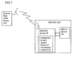
- This scenario is illustrated in fig 7 , with the first radio link extending between the local device 120 and the remote device 110.
- the local device 120 incorporates both coexisting radio devices Bluetooth device 10 and 802.11 device 30 in this example.
- the air quality estimation algorithm of the remote device can cause a reduced data rate and change in modulation level since it sees many retransmissions and it is not aware of the existence of the coexistence mechanism.
- the problem can be addressed in at least two ways:
Landscapes
- Engineering & Computer Science (AREA)
- Computer Networks & Wireless Communication (AREA)
- Signal Processing (AREA)
- Quality & Reliability (AREA)
- Mobile Radio Communication Systems (AREA)
- Small-Scale Networks (AREA)
Description
- Field of the invention: This invention relates to devices having a radio transmitter with a coexistence controller, to corresponding methods of controlling transmissions, and to integrated circuits or software for carrying out such methods.
- Description of the Related Art: It is known to provide radio links with automatically variable data rates. If the channel quality of the link changes owing to fading caused by movement or other changes in the air transmission path, this can be detected by a monitor and the data rate can be changed to suit or maximize the data transmissible over the link at the given time. It is also known to provide a coexistence control arranged to communicate with another radio transmitter suitable for part of another radio link, to control transmissions to enable both radio links to use potentially conflicting transmission frequencies.
- Conflicts between wireless transmissions using the same frequency band are known. Conflicts can be very troublesome when the transmitters are very close to each other, e.g. a lap top computer with both a wireless Bluetooth and a "WiFi" (IEEE 802.11) transmitter operating in the same frequency band. One way to control such conflicts is to provide some form of coexistence etiquette which controls transmissions so as to reduce the problem.
-
US 2002/0065907 A1 discloses a device having a radio transmitter for a first radio link and having a coexistence controller arranged to communicate with another radio transmitter for another radio link (i.e. BT-WLAN system hardware coexistence interface) and to control transmission to enable both radio links to use potentially conflicting transmission frequencies (i.e. WLAN/BT coexistence) the radio transmitter also having a link monitor arranged to monitor the first radio link (i.e. a rate fallback mechanism after a number of unsuccessful communications) according to an output from the coexistence controller (i.e. the rate fallback mechanism of the WLAN is disabled in a collocated WLAN/BT during periods in which the collocated BT system may transmit). The WLAN link controller is disabled when BT transmits. - An object of the invention is to provide improved devices having a radio transmitter with a coexistence controller, to corresponding methods of controlling transmissions, and to integrated circuits or software for carrying out such methods. According to a first aspect, the invention provides:
A device having a first radio transmitter for supporting a first radio link,
the radio transmitter having a coexistence controller arranged to communicate with a second radio transmitter for supporting a second radio link, and to control transmission times of the first and second transmitter to enable both radio links to use potentially conflicting transmission frequencies as defined in claim 1.
The transmitter and the other transmitter may be located within 1 meter of each other.
By making the link monitor dependent on an input from the coexistence controller, a number of consequences can arise. For example the link monitor can more easily distinguish between transmission losses caused by the coexistence control, and those caused by other effects. This in turn can help avoid or reduce the risk of a data rate controller being fooled into unnecessarily reducing a transmission rate if transmission losses caused by the coexistence control are misinterpreted as a drop in link quality. The monitor output can be used for purposes other than rate control. Other consequences can be envisaged. Embodiments of the invention can involve any type of radio transmitter, any form of coexistence interface, and any form of link monitor. Embodiments can have any other additional features. Some additional features are described in more detail below. For example, the monitoring of an error rate of the link can be suspended in accordance with an output from the coexistence controller. Or the error rate can be determined by ignoring errors that occur during the a time determined by the output of the coexistence controller, i.e. during the time that the coexistence controller prevents one of the devices from transmitting.
Another aspect of the invention can be summarized as a method of controlling radio transmissions as defined in claim 8. - Further aspects are according to the dependent claims.
- How the present invention may be put into effect will now be described by way of example with reference to the appended drawings, in which:
-
Fig. 1 shows radio transmitters having a coexistence mechanism, -
Figs 2 ,3 and 4 show timing charts of transmissions of transmitters having a coexisting mechanism, -
Fig 5 shows radio transmitters having a coexistence mechanism according to an embodiment of the invention, -
Fig 6 shows another embodiment, and -
Fig 7 shows another embodiment having a remote device. - The present invention will be described with respect to particular embodiments and with reference to certain drawings but the invention is not limited thereto but only by the claims. The drawings described are only schematic and are non-limiting. In the drawings, the size of some of the elements may be exaggerated and not drawn on scale for illustrative purposes. Where the term "comprising" is used in the present description and claims, it does not exclude other elements or steps. Where an indefinite or definite article is used when referring to a singular noun e.g. "a" or "an", "the", this includes a plural of that noun unless something else is specifically stated.
- The term "comprising", used in the claims, should not be interpreted as being restricted to the means listed thereafter; it does not exclude other elements or steps. Thus, the scope of the expression "a device comprising means A and B" should not be limited to devices consisting only of components A and B. It means that with respect to the present invention, the only relevant components of the device are A and B.
- Furthermore, the terms first, second, third and the like in the description and in the claims, are used for distinguishing between similar elements and not necessarily for describing a sequential or chronological order. It is to be understood that the terms so used are interchangeable under appropriate circumstances and that the embodiments of the invention described herein are capable of operation in other sequences than described or illustrated herein.
- Moreover, the terms top, bottom, over, under and the like in the description and the claims are used for descriptive purposes and not necessarily for describing relative positions. It is to be understood that the terms so used are interchangeable under appropriate circumstances and that the embodiments of the invention described herein are capable of operation in other orientations than described or illustrated herein.
- Some embodiments of the invention, involve channel quality driven modulation change in multi-modulation wireless systems in case of frequency band sharing. By way of introduction to the embodiments, a problem will be described. Several wireless systems support variable data rates by varying their modulation scheme: for example recent Bluetooth standards (see http://www.bluetooth.org/spec/) supports 1 Mbps Physical rate (using GFSK modulation (Gaussian Frequency Shift Keying)), 2 Mbps Physical rate (using pi/4DQPSK modulation, (Differential Quadrature Phase Shift Keying)) and 3Mbps Physical rate (using 8-DPSK modulation, (Differential Phase Shift Keying)). IEEE 802.11b supports DSS (Distribution system Services) and CCK (Complemenatry Code Keying) modulations with physical rates from 1 to 11 Mbps and 802.11g (http:Hgrouper.ieee.org/groups/802/11/) is OFDM (Orthogonal Frequency Division Multiplexing) based with a physical rate up to 54 Mbps.
- A lower physical transmission rate implies mainly two things:
- For the same throughput a longer air occupation
- A higher resistance to noise and interference (usually).
- Wireless systems supporting more than one modulation type can embed a monitor in the form of an algorithm capable of estimating the level of disturbance or interference present on the air interface. In some examples this can be done by making a count or some other assessment of the incorrectly received or not received packets and hence also a determination of needed retransmissions. The worse the quality of the air interface, the higher the bit error rate, the frame error rate, the symbol error rate or any other measure of the quality of received packets. Hence a monitor algorithm will assume that if any of these received signal quality measures are poor, that some adaptation is required. For example, the output of the monitor can be used by a controller to cause an automatic lowering of the data rate by changing the modulation if the algorithm deduces a drop in quality of the air link. In Bluetooth this feature is called CQDDR (Channel Quality Driven Data Rate).
Wireless systems like those defined by the Bluetooth and IEEE 802.11 standards share the same ISM (Industrial, Scentific and Medical) band situated at 2.4GHz. When any two radio transmitter devices, such as Bluetooth device and an IEEE 802.11 device, are placed within range, such as when they are incorporated in any way in the same product at a very close distance, perhaps a few centimeters apart (in the collocated scenario), it is useful to add a coexistence method that uses information exchange to coordinate some time sharing between the two devices to enable them to coexist using conflicting frequencies. The transmitters which may conflict may be located within 1 meter of each other. - A popular coexistence mechanism is called PTA (Packet Traffic Arbitration). An overall view including a coexistence mechanism in a collocated scenario is shown in
fig. 1 . This shows aBluetooth device 10, an IEEE 802.11device 30, and a coexistence bus 20 used by the two devices (could be 1, 2 or more physical lines) to exchange real time information. In principle the coexistence bus could be implemented using any kind of communication link including a wired link, an optical link, another radio link or links etc. Each of the devices has their own largely independent radio links to other devices (not shown).
What usually happens is that when one of the two devices has to do an RF transmission or has receiving activity considered vital for the application it requests the other device not to perform any RF activity (or at least no transmissions (TX)). If the second device is already doing something it should stop it within a time T.
This would cause on one or both links a certain number of missed packets and hence retransmissions forced by the coexistence mechanism. These retransmissions are forced by the coexistence mechanism and not directly by poorer air link quality. However, the monitor algorithm checking the link air quality will then observe an increased number of retransmissions, and deduce from this that the air quality has been degraded. The response to a degraded air interface is to change modulation, i.e. reduce data rate. The monitor algorithm will therefore cause a controller to change the modulation type and lower the physical rate of the transmissions. This change of modulation is actually unnecessary - the air interface can support the original modulation satisfactorily.
The consequence of changing the modulation in this situation is an increase in the air occupation per bit and therefore an increase in the chance of having the coexistence mechanism stop one or the other of the radio links. This further stop will increase the number of retransmissions due to the coexistence - triggering yet a further decrease in bit rate by increasing the complexity of the modulation scheme. This could avalanche in the sense of more retransmissions causing more severe stopping by the coexistence mechanism, triggering yet further rate decrease, meaning increase of air occupation per bit and so on. At least one of the two systems could become unusable.
A typical example is illustrated in timing charts offigs 2 ,3 and 4 . When a voice link is running over Bluetooth using the HV3 packet, voice communication will occur every 2.5 µs as shown infig. 2 . The IEEE 802.11 device is requested not to operate when voice traffic is ongoing on the Bluetooth side (at least not to do any TX). Therefore, for the IEEE 802.11 device, only packets scheduled in between those Bluetooth voice slots will be successfully transmitted as shown infig. 3 . If the IEEE 802.11 device is using a physical rate of 11Mbps the packet may fit the 2.5us but some times the packet will coincide with those of the other link and so may be killed by the coexistence mechanism.
If the rate controller receives an indication from the air link monitor that the air link is bad since some packets have been lost, it lowers the physical rate as shown infig 4 . This shows the effect that increasing the air length of the packet increases the chances of having a packet killed by the coexistence mechanism as shown infig. 4 . If the algorithm sees even more retransmissions it may decide to go to the lowest physical rate where the air length of a packet is longer then 2.5us therefore no transmission becomes possible on the 802.11 side. A similar case can be presented where the Bluetooth is suffering the same side effect.
To address this, an embodiment of the invention provides the monitor with an input from the coexistence controller. This can be in the form of a loop back from the coexistence mechanism to the air quality estimation algorithm to tell it that the current retransmission was not due to a problem on the air link, but due to the coexistence mechanism itself. In this case the air quality estimation algorithm will not take into account retransmissions due to the coexistence mechanism.Fig 5 shows an embodiment based on the arrangement shown infig 1 and corresponding reference numerals have been used as appropriate. Acoexistence controller corresponding monitor 150 is provided.
A possible implementation is to provide a counter for the retransmissions due to coexistence mechanism and subtract this value from the general retransmission counter. The rate controller can make a decision on whether to alter the modulation type and therefore the data rate, periodically, according to the general retransmission counter after the subtraction, and according to other conventional input parameters such as recent history of the retransmission rate, and time since last change and so on. Other implementations can be envisaged. The counter may be located in a remote device or in the device having the two conflicting transmitters. In case of a remote device, the count may be sent over the air interface.
For example,Fig 6 shows another implementation in which arate control part 70 is provided in the Bluetooth device. The rate control part has a monitor in the form of a channel quality monitor 80, and the determined channel quality is used to control the rate of transmission according to the Bluetooth standard. Clearly this is applicable to other standards allowing variable rates of transmission.
In accordance with the present invention, the monitor algorithm can be done in any of a number of different ways, each one being an embodiment of the present invention. For example, one way is to measure the number of correctly received packets (e.g. packet received with correct CRC). In this case, at every received packet a counter will be incremented if the CRC is not correctly decoded. If within a certain time, e.g. a predetermined time or a dynamically set time, T the counter exceeds a threshold, e.g. a predetermined threshold or a dynamically set threshold, then the algorithm decides to ask for a modulation change. Dynamical setting of the time T or the threshold can have the advantage that the operation is adjusted according to a traffic parameter, such as the traffic load or to a quality of service parameter, e.g. the quality of signals received over the air interface. For example, packets that are stopped by the coexistence mechanism while they are not completely received will increase this counter. So preferably these should not be taken into account. - A second problem will now be considered, which can arise in some embodiments. In a communication between two radio devices where only one is collocated, and the other is remote, the collocated device will know that the retransmission are coming from the coexistence mechanism while the remote device will not know. This scenario is illustrated in
fig 7 , with the first radio link extending between thelocal device 120 and theremote device 110. Thelocal device 120 incorporates both coexisting radiodevices Bluetooth device 10 and 802.11device 30 in this example.
The air quality estimation algorithm of the remote device can cause a reduced data rate and change in modulation level since it sees many retransmissions and it is not aware of the existence of the coexistence mechanism. The problem can be addressed in at least two ways: - Having the collocated device able to refuse the modulation type change. An advantage of this solution is that the implementation can be fully local in the collocated device and does not need to be implemented in the remote device, meaning compatibility with older remote devices is maintained.
- Informing the non collocated device (by a specific command transmitted over the air interface) that it should not activate the air estimation algorithm since the other device is in collocated coexisting scenario. In this case, as a specific command is exchanged between the devices, and hence this command must be known by both parties.
As has been described, additional features can involve the device having the other radio transmitter incorporated. Another is the radio transmitter being arranged to vary its transmission data rate, or the data rate of transmissions received by the device over the first link, according to an output of the monitor. Another is the variable transmission rate involving varying a modulation type. Another is the monitor being arranged to monitor an error rate of the link. Another is the error rate comprising any of a rate of retransmissions, rate of bit errors, rate of packet errors, and rate of missing packets. Another is the radio transmitter being arranged to pass an input from the coexistence controller over the first radio link. Another is the transmitter having a range of less than 1km. Another is the transmitter having a range of less than 100m. Another is the radio transmitter comprising any of a Bluetooth type transmitter or an IEEE 802.11 type transmitter.
As an additional feature, applicable to any of the embodiments of the present invention, information on the number of packets killed by the coexistence mechanism can be reused in accordance with the present invention by the modulation change algorithm to change, e.g. increase the modulation type.
The monitor, the coexistence controller and the rate controller can be implemented as software in any programming language running on conventional processing hardware, or as application specific circuitry for example, following established practice.
Other additional features and variations can be envisaged within the scope of the claims.
Claims (13)
- A device having a first radio transmitter (10) for supporting a first radio link, the radio transmitter having a coexistence controller (60) arranged to communicate with a second radio transmitter (30) for supporting a second radio link, and to control transmission times of the first transmitter and the second transmitter to enable both radio links to use potentially conflicting transmission frequencies,
characterised in that the first radio transmitter also has a link monitor (50) arranged to count retransmissions on the first radio link, and wherein the link monitor (50) is provided with an output from the coexistence controller (60) which indicates when a retransmission is caused by the coexistence controller and the link monitor (50) is arranged to subtract a count of retransmissions caused by the coexistence controller from the count of retransmissions on the first radio link. - The device of claim 1 and having the second radio transmitter incorporated in the device (120).
- The device of claim 1 or 2, the first radio transmitter having a rate controller (70) arranged to vary a transmission data rate, or the data rate of transmissions received by the device over the first link, according to an output of the monitor.
- The device of claim 3 arranged to vary the data rate by varying a modulation type.
- The device of any preceding claim, the first radio transmitter being arranged to pass an output from the coexistence controller over the first radio link.
- The device of any preceding claim, the first radio transmitter having a range of less than 100m.
- The device of any preceding claim, the first radio transmitter comprising any of a Bluetooth type transmitter (10) or an IEEE 802.11 type transmitter (30).
- A method of controlling radio transmissions over a first radio link, having the steps of:controlling transmission times over the first radio link and over a second radio link according to a coexistence algorithm to enable the first radio link and the second link to use potentially conflicting transmission frequencies, and characterised by:counting retransmissions on the first radio link,receiving an output of the coexistence algorithm which indicates when a retransmission is caused by the coexistence algorithm and counting retransmissions caused by the coexistence algorithm, andsubtracting a count of retransmissions caused by the coexistence algorithm from a count of retransmissions on the first radio link.
- The method of claim 8, having the step of varying a transmission data rate, or the data rate of transmissions received by the device over the first link, according to an output of the monitor.
- The method of claim 8 or 9, varying the data rate by varying a modulation type.
- The method of any of claims 8 to 10, having the step of passing an output from the coexistence algorithm over the first radio link.
- A program for a computer comprising code for carrying out the method of any of claims 8 to 11, when executed on a data-processing apparatus.
- The device of any of claims 1 to 7, wherein the link monitor, the coexistence controller and the rate controller are implemented in the form of an integrated circuit.
Priority Applications (3)
| Application Number | Priority Date | Filing Date | Title |
|---|---|---|---|
| EP07003400A EP1959612B1 (en) | 2007-02-19 | 2007-02-19 | Radio coexistence mechanism for variable data rate radio links |
| DE602007010416T DE602007010416D1 (en) | 2007-02-19 | 2007-02-19 | Radio coexistence mechanism for variable data rate radio links |
| US12/032,076 US8185058B2 (en) | 2007-02-19 | 2008-02-15 | Radio coexistence mechanism for variable data rate radio links |
Applications Claiming Priority (1)
| Application Number | Priority Date | Filing Date | Title |
|---|---|---|---|
| EP07003400A EP1959612B1 (en) | 2007-02-19 | 2007-02-19 | Radio coexistence mechanism for variable data rate radio links |
Publications (2)
| Publication Number | Publication Date |
|---|---|
| EP1959612A1 EP1959612A1 (en) | 2008-08-20 |
| EP1959612B1 true EP1959612B1 (en) | 2010-11-10 |
Family
ID=38236515
Family Applications (1)
| Application Number | Title | Priority Date | Filing Date |
|---|---|---|---|
| EP07003400A Active EP1959612B1 (en) | 2007-02-19 | 2007-02-19 | Radio coexistence mechanism for variable data rate radio links |
Country Status (3)
| Country | Link |
|---|---|
| US (1) | US8185058B2 (en) |
| EP (1) | EP1959612B1 (en) |
| DE (1) | DE602007010416D1 (en) |
Families Citing this family (23)
| Publication number | Priority date | Publication date | Assignee | Title |
|---|---|---|---|---|
| US8280368B2 (en) * | 2005-04-07 | 2012-10-02 | Qualcomm Incorporated | Method and system for re-acquiring signals of a wireless broadcast network |
| KR20100082106A (en) * | 2009-01-08 | 2010-07-16 | 삼성전자주식회사 | Data transfer method based on wi-fi multimedia and apparatus thereof |
| US8184580B2 (en) * | 2009-02-12 | 2012-05-22 | Telefonaktiebolaget L M Ericsson (Publ) | Data packet communication scheduling in a communication system |
| US9119215B2 (en) * | 2009-08-31 | 2015-08-25 | Qualcomm Incorporated | Method and apparatus for enhanced packet traffic arbitration |
| US8340578B2 (en) | 2009-10-05 | 2012-12-25 | Apple Inc. | Methods and apparatus for enhanced coexistence algorithms in wireless systems |
| US8693569B2 (en) * | 2009-10-19 | 2014-04-08 | Apple Inc. | Methods and apparatus for dynamic wireless device coexistence |
| JP2012014452A (en) * | 2010-06-30 | 2012-01-19 | Fujitsu Ltd | Information processor, information processing program and information processing method |
| CN102763094A (en) * | 2010-07-19 | 2012-10-31 | 高通股份有限公司 | Method and apparatus for enhanced packet traffic arbitration |
| US9344306B2 (en) * | 2010-08-09 | 2016-05-17 | Mediatek Inc. | Method for dynamically adjusting signal processing parameters for processing wanted signal and communications apparatus utilizing the same |
| EP2622927B1 (en) * | 2010-10-01 | 2017-09-20 | BlackBerry Limited | Method and apparatus for avoiding in-device coexistence interference |
| US8599709B2 (en) | 2011-02-10 | 2013-12-03 | Apple Inc. | Methods and apparatus for wireless coexistence based on transceiver chain emphasis |
| US8805303B2 (en) | 2011-02-18 | 2014-08-12 | Blackberry Limited | Method and apparatus for avoiding in-device coexistence interference with preferred frequency notification |
| US8965286B2 (en) * | 2011-05-13 | 2015-02-24 | Nokia Corporation | Inquiry response event control |
| US9060280B2 (en) | 2011-07-29 | 2015-06-16 | Blackberry Limited | Enhanced in-device coexistence interference avoidance using predetermined downlink channel |
| US8842602B2 (en) | 2011-07-29 | 2014-09-23 | Blackberry Limited | Enhancement of in-device coexistence interference avoidance |
| US8995929B2 (en) | 2011-12-06 | 2015-03-31 | Apple Inc. | Methods and apparatus for wireless optimization based on platform configuration and use cases |
| WO2013089747A1 (en) * | 2011-12-15 | 2013-06-20 | Intel Corporation | System and method for enabling low power devices |
| US9143957B2 (en) * | 2012-02-24 | 2015-09-22 | Qualcomm Incorporated | Mitigating cross-device interference |
| US8995553B2 (en) * | 2012-06-08 | 2015-03-31 | Apple Inc. | Methods and apparatus for mitigating interference in aggressive form factor designs |
| US10038578B2 (en) * | 2016-03-31 | 2018-07-31 | Telefonaktiebolaget Lm Ericsson (Publ) | Multi-modulation transmitter, receiver and methods for handling multi-modulation in wireless communication systems |
| EP3437281B1 (en) | 2016-03-31 | 2019-12-25 | Telefonaktiebolaget LM Ericsson (PUBL) | Multi-modulation receiver, transmitters and methods for handling multi-modulation in wireless communication systems |
| US11120811B2 (en) * | 2018-08-29 | 2021-09-14 | Qualcomm Incorporated | Power optimized link quality detection and feedback |
| CN112260778B (en) * | 2020-10-16 | 2023-02-14 | 展讯半导体(成都)有限公司 | Method for evaluating broadcast channel and related product |
Family Cites Families (14)
| Publication number | Priority date | Publication date | Assignee | Title |
|---|---|---|---|---|
| US6795418B2 (en) * | 2000-03-31 | 2004-09-21 | Koninklijke Philips Electronics N.V. | Wireless MAC protocol based on a hybrid combination of slot allocation, token passing, and polling for isochronous traffic |
| US6954616B2 (en) * | 2001-03-22 | 2005-10-11 | Transdimension, Inc. | Top-level controller for wireless communication devices and protocols |
| US8364080B2 (en) * | 2002-08-01 | 2013-01-29 | Broadcom Corporation | Method and system for achieving enhanced quality and higher throughput for collocated IEEE 802.11 B/G and bluetooth devices in coexistent operation |
| US20040192222A1 (en) * | 2003-03-26 | 2004-09-30 | Nokia Corporation | System and method for semi-simultaneously coupling an antenna to transceivers |
| US7406296B2 (en) * | 2003-08-22 | 2008-07-29 | Telefonaktiebolaget L M Ericsson (Publ) | Co-located radio operation |
| EP1513281A1 (en) * | 2003-09-05 | 2005-03-09 | Motorola Inc. | A method and apparatus for link adaptation for packet transmission |
| US7610057B2 (en) * | 2004-04-23 | 2009-10-27 | Microsoft Corporation | Selecting a wireless networking technology on a device capable of carrying out wireless network communications via multiple wireless technologies |
| US7280836B2 (en) * | 2004-04-30 | 2007-10-09 | Symbol Technologies, Inc. | System and method for coexistence in wireless networks |
| US7440728B2 (en) * | 2004-12-03 | 2008-10-21 | Microsoft Corporation | Use of separate control channel to mitigate interference problems in wireless networking |
| US20060239223A1 (en) * | 2005-04-21 | 2006-10-26 | Itay Sherman | Method and system for bluetooth and wireless local area network coexistence |
| US9059782B2 (en) * | 2005-06-01 | 2015-06-16 | Broadcom Corporation | Method and system for antenna and radio front-end topologies for a system-on-a-chip (SOC) device that combines bluetooth and IEEE 802.11 b/g WLAN technologies |
| US9031604B2 (en) * | 2005-06-02 | 2015-05-12 | Broadcom Corporation | Method and apparatus for enabling simultaneous VoWLAN and Bluetooth audio in small form factor handheld devices |
| US20060292986A1 (en) * | 2005-06-27 | 2006-12-28 | Yigal Bitran | Coexistent bluetooth and wireless local area networks in a multimode terminal and method thereof |
| US20060292987A1 (en) * | 2005-06-27 | 2006-12-28 | Lior Ophir | Method of wireless local area network and Bluetooth network coexistence in a collocated device |
-
2007
- 2007-02-19 DE DE602007010416T patent/DE602007010416D1/en active Active
- 2007-02-19 EP EP07003400A patent/EP1959612B1/en active Active
-
2008
- 2008-02-15 US US12/032,076 patent/US8185058B2/en active Active
Also Published As
| Publication number | Publication date |
|---|---|
| US20080200124A1 (en) | 2008-08-21 |
| US8185058B2 (en) | 2012-05-22 |
| EP1959612A1 (en) | 2008-08-20 |
| DE602007010416D1 (en) | 2010-12-23 |
Similar Documents
| Publication | Publication Date | Title |
|---|---|---|
| US8185058B2 (en) | Radio coexistence mechanism for variable data rate radio links | |
| US6882635B2 (en) | Coexistence between interfering communication systems | |
| US8107999B2 (en) | Communication device and method of communicating transmissions | |
| CN105722097B (en) | Channel detection method, Channel Detection device and terminal | |
| JP5148756B2 (en) | Radio station | |
| EP3621227B1 (en) | In-device coexistence of wireless communication technologies | |
| CN102957455B (en) | Wireless communication apparatus and interference avoidance method | |
| JP4625128B2 (en) | Method, apparatus and computer readable recording medium for adapting transmission settings | |
| JP5852128B2 (en) | Communication technology for bursty noise environments | |
| EP2738960A1 (en) | Wireless communication system and wireless communication device | |
| US9629202B2 (en) | In-device coexistence of multiple wireless communication technologies | |
| CN101971678B (en) | Base station device and communication control method | |
| MXPA04008194A (en) | Wireless communication system, wireless communication device and wireless communication method, and computer program. | |
| EP2257087A1 (en) | Wireless terminal and retransmission method | |
| WO2013006988A1 (en) | Methods and apparatuses for provision of a flexible time sharing scheme on an unlicensed band of a system | |
| WO2015179811A1 (en) | Unlicensed frequency band with licensed frequency band timing | |
| US20120075987A1 (en) | Radio apparatus, method for communication disturbance remedial action and program for communication disturbance remedial action | |
| CN102292937A (en) | Method for reducing interference between two communication systems operating in adjacent frequency bands | |
| EP3205164A1 (en) | Transmission coordination for collocated radios | |
| EP3254382A1 (en) | Coexistence interference mitigation management for multi-user mimo systems | |
| CN108029137A (en) | Contention Window Adjustment in License-Free Cellular Radio Networks | |
| WO2012095161A1 (en) | Error control in a communication system | |
| JP6938526B2 (en) | Link adaptation to license-assisted access carriers | |
| CN102056303A (en) | Scheduling information trigging method, and carrier activation control method and device | |
| JP2006135891A (en) | Wireless communication method |
Legal Events
| Date | Code | Title | Description |
|---|---|---|---|
| PUAI | Public reference made under article 153(3) epc to a published international application that has entered the european phase |
Free format text: ORIGINAL CODE: 0009012 |
|
| AK | Designated contracting states |
Kind code of ref document: A1 Designated state(s): AT BE BG CH CY CZ DE DK EE ES FI FR GB GR HU IE IS IT LI LT LU LV MC NL PL PT RO SE SI SK TR |
|
| AX | Request for extension of the european patent |
Extension state: AL BA HR MK RS |
|
| 17P | Request for examination filed |
Effective date: 20090126 |
|
| 17Q | First examination report despatched |
Effective date: 20090225 |
|
| AKX | Designation fees paid |
Designated state(s): DE FR GB IT |
|
| RIC1 | Information provided on ipc code assigned before grant |
Ipc: H04W 8/08 20090101AFI20100208BHEP |
|
| GRAP | Despatch of communication of intention to grant a patent |
Free format text: ORIGINAL CODE: EPIDOSNIGR1 |
|
| RAP1 | Party data changed (applicant data changed or rights of an application transferred) |
Owner name: ST-ERICSSON BELGIUM NV |
|
| RIC1 | Information provided on ipc code assigned before grant |
Ipc: H04L 1/00 20060101ALI20100505BHEP Ipc: H04W 88/06 20090101ALI20100505BHEP Ipc: H04W 8/08 20090101AFI20100505BHEP |
|
| GRAS | Grant fee paid |
Free format text: ORIGINAL CODE: EPIDOSNIGR3 |
|
| GRAA | (expected) grant |
Free format text: ORIGINAL CODE: 0009210 |
|
| AK | Designated contracting states |
Kind code of ref document: B1 Designated state(s): DE FR GB IT |
|
| REG | Reference to a national code |
Ref country code: GB Ref legal event code: FG4D |
|
| REF | Corresponds to: |
Ref document number: 602007010416 Country of ref document: DE Date of ref document: 20101223 Kind code of ref document: P |
|
| PLBE | No opposition filed within time limit |
Free format text: ORIGINAL CODE: 0009261 |
|
| STAA | Information on the status of an ep patent application or granted ep patent |
Free format text: STATUS: NO OPPOSITION FILED WITHIN TIME LIMIT |
|
| 26N | No opposition filed |
Effective date: 20110811 |
|
| REG | Reference to a national code |
Ref country code: DE Ref legal event code: R097 Ref document number: 602007010416 Country of ref document: DE Effective date: 20110811 |
|
| PG25 | Lapsed in a contracting state [announced via postgrant information from national office to epo] |
Ref country code: IT Free format text: LAPSE BECAUSE OF FAILURE TO SUBMIT A TRANSLATION OF THE DESCRIPTION OR TO PAY THE FEE WITHIN THE PRESCRIBED TIME-LIMIT Effective date: 20101110 |
|
| REG | Reference to a national code |
Ref country code: FR Ref legal event code: PLFP Year of fee payment: 10 |
|
| REG | Reference to a national code |
Ref country code: FR Ref legal event code: PLFP Year of fee payment: 11 |
|
| REG | Reference to a national code |
Ref country code: FR Ref legal event code: PLFP Year of fee payment: 12 |
|
| PGFP | Annual fee paid to national office [announced via postgrant information from national office to epo] |
Ref country code: GB Payment date: 20260121 Year of fee payment: 20 |
|
| PGFP | Annual fee paid to national office [announced via postgrant information from national office to epo] |
Ref country code: DE Payment date: 20260121 Year of fee payment: 20 |
|
| PGFP | Annual fee paid to national office [announced via postgrant information from national office to epo] |
Ref country code: FR Payment date: 20260121 Year of fee payment: 20 |