EP1959603A1 - Method of radio data emission, emitter and receiver using the method - Google Patents
Method of radio data emission, emitter and receiver using the method Download PDFInfo
- Publication number
- EP1959603A1 EP1959603A1 EP07003191A EP07003191A EP1959603A1 EP 1959603 A1 EP1959603 A1 EP 1959603A1 EP 07003191 A EP07003191 A EP 07003191A EP 07003191 A EP07003191 A EP 07003191A EP 1959603 A1 EP1959603 A1 EP 1959603A1
- Authority
- EP
- European Patent Office
- Prior art keywords
- frequency
- symbols
- antenna
- signals
- frequencies
- Prior art date
- Legal status (The legal status is an assumption and is not a legal conclusion. Google has not performed a legal analysis and makes no representation as to the accuracy of the status listed.)
- Withdrawn
Links
Images


Classifications
-
- H—ELECTRICITY
- H04—ELECTRIC COMMUNICATION TECHNIQUE
- H04L—TRANSMISSION OF DIGITAL INFORMATION, e.g. TELEGRAPHIC COMMUNICATION
- H04L1/00—Arrangements for detecting or preventing errors in the information received
- H04L1/02—Arrangements for detecting or preventing errors in the information received by diversity reception
- H04L1/06—Arrangements for detecting or preventing errors in the information received by diversity reception using space diversity
-
- H—ELECTRICITY
- H04—ELECTRIC COMMUNICATION TECHNIQUE
- H04B—TRANSMISSION
- H04B7/00—Radio transmission systems, i.e. using radiation field
- H04B7/02—Diversity systems; Multi-antenna system, i.e. transmission or reception using multiple antennas
- H04B7/04—Diversity systems; Multi-antenna system, i.e. transmission or reception using multiple antennas using two or more spaced independent antennas
- H04B7/06—Diversity systems; Multi-antenna system, i.e. transmission or reception using multiple antennas using two or more spaced independent antennas at the transmitting station
- H04B7/0613—Diversity systems; Multi-antenna system, i.e. transmission or reception using multiple antennas using two or more spaced independent antennas at the transmitting station using simultaneous transmission
- H04B7/0667—Diversity systems; Multi-antenna system, i.e. transmission or reception using multiple antennas using two or more spaced independent antennas at the transmitting station using simultaneous transmission of delayed versions of same signal
-
- H—ELECTRICITY
- H04—ELECTRIC COMMUNICATION TECHNIQUE
- H04B—TRANSMISSION
- H04B7/00—Radio transmission systems, i.e. using radiation field
- H04B7/02—Diversity systems; Multi-antenna system, i.e. transmission or reception using multiple antennas
- H04B7/04—Diversity systems; Multi-antenna system, i.e. transmission or reception using multiple antennas using two or more spaced independent antennas
- H04B7/06—Diversity systems; Multi-antenna system, i.e. transmission or reception using multiple antennas using two or more spaced independent antennas at the transmitting station
-
- H—ELECTRICITY
- H04—ELECTRIC COMMUNICATION TECHNIQUE
- H04B—TRANSMISSION
- H04B7/00—Radio transmission systems, i.e. using radiation field
- H04B7/02—Diversity systems; Multi-antenna system, i.e. transmission or reception using multiple antennas
- H04B7/04—Diversity systems; Multi-antenna system, i.e. transmission or reception using multiple antennas using two or more spaced independent antennas
- H04B7/06—Diversity systems; Multi-antenna system, i.e. transmission or reception using multiple antennas using two or more spaced independent antennas at the transmitting station
- H04B7/0613—Diversity systems; Multi-antenna system, i.e. transmission or reception using multiple antennas using two or more spaced independent antennas at the transmitting station using simultaneous transmission
- H04B7/068—Diversity systems; Multi-antenna system, i.e. transmission or reception using multiple antennas using two or more spaced independent antennas at the transmitting station using simultaneous transmission using space frequency diversity
-
- H—ELECTRICITY
- H04—ELECTRIC COMMUNICATION TECHNIQUE
- H04L—TRANSMISSION OF DIGITAL INFORMATION, e.g. TELEGRAPHIC COMMUNICATION
- H04L1/00—Arrangements for detecting or preventing errors in the information received
- H04L1/02—Arrangements for detecting or preventing errors in the information received by diversity reception
- H04L1/06—Arrangements for detecting or preventing errors in the information received by diversity reception using space diversity
- H04L1/0618—Space-time coding
- H04L1/0637—Properties of the code
- H04L1/0668—Orthogonal systems, e.g. using Alamouti codes
-
- H—ELECTRICITY
- H04—ELECTRIC COMMUNICATION TECHNIQUE
- H04B—TRANSMISSION
- H04B7/00—Radio transmission systems, i.e. using radiation field
- H04B7/02—Diversity systems; Multi-antenna system, i.e. transmission or reception using multiple antennas
- H04B7/04—Diversity systems; Multi-antenna system, i.e. transmission or reception using multiple antennas using two or more spaced independent antennas
- H04B7/06—Diversity systems; Multi-antenna system, i.e. transmission or reception using multiple antennas using two or more spaced independent antennas at the transmitting station
- H04B7/0613—Diversity systems; Multi-antenna system, i.e. transmission or reception using multiple antennas using two or more spaced independent antennas at the transmitting station using simultaneous transmission
- H04B7/0667—Diversity systems; Multi-antenna system, i.e. transmission or reception using multiple antennas using two or more spaced independent antennas at the transmitting station using simultaneous transmission of delayed versions of same signal
- H04B7/0669—Diversity systems; Multi-antenna system, i.e. transmission or reception using multiple antennas using two or more spaced independent antennas at the transmitting station using simultaneous transmission of delayed versions of same signal using different channel coding between antennas
-
- H—ELECTRICITY
- H04—ELECTRIC COMMUNICATION TECHNIQUE
- H04B—TRANSMISSION
- H04B7/00—Radio transmission systems, i.e. using radiation field
- H04B7/02—Diversity systems; Multi-antenna system, i.e. transmission or reception using multiple antennas
- H04B7/04—Diversity systems; Multi-antenna system, i.e. transmission or reception using multiple antennas using two or more spaced independent antennas
- H04B7/06—Diversity systems; Multi-antenna system, i.e. transmission or reception using multiple antennas using two or more spaced independent antennas at the transmitting station
- H04B7/0613—Diversity systems; Multi-antenna system, i.e. transmission or reception using multiple antennas using two or more spaced independent antennas at the transmitting station using simultaneous transmission
- H04B7/0667—Diversity systems; Multi-antenna system, i.e. transmission or reception using multiple antennas using two or more spaced independent antennas at the transmitting station using simultaneous transmission of delayed versions of same signal
- H04B7/0671—Diversity systems; Multi-antenna system, i.e. transmission or reception using multiple antennas using two or more spaced independent antennas at the transmitting station using simultaneous transmission of delayed versions of same signal using different delays between antennas
Definitions
- the invention concerns the domain of wireless communication, and more specifically the coding and decoding schemes useful in the context of MIMO (Multiple Input Multiple Output) or MISO (Multiple Input Single Output) communications especially used in conjunction of OFDM-like transmission schemes.
- MIMO Multiple Input Multiple Output
- MISO Multiple Input Single Output
- Orthogonal Frequency-Division Multiplexing like Coded OFDM (COFDM), is based upon the principle of frequency-division multiplexing (FDM), but is implemented as a digital modulation scheme.
- the bit stream to be transmitted is split into several parallel bit streams, typically dozens to thousands.
- the available frequency spectrum is divided into several sub-channels, and each low-rate bit stream is transmitted over one sub-channel by modulating a sub-carrier using a standard modulation scheme, for example PSK, QAM, etc.
- the sub-carrier frequencies are chosen so that the modulated data streams are orthogonal to each other, meaning that cross talk between the sub-channels is eliminated. This orthogonality occurs when sub-carriers are equally spaced by the symbol rate of a sub-carrier.
- OFDM orthogonal advantage of OFDM is its ability to cope with severe channel conditions, for example, multipath and narrowband interference, without complex equalization filters.
- Channel equalization is simplified by using many slowly modulated narrowband signals instead of one rapidly modulated wideband signal.
- DFT spread OFDM A variation called DFT spread OFDM has been developed.
- each symbol to be transmitted is spread over a set of transmitted frequencies by a DFT (Discrete Fourier Transform), the resulting signal is sent over a conventional OFDM transmission system.
- DFT Discrete Fourier Transform
- Fig. 1 illustrates the coding implementation in the frequency domain for the transmitter. Actual implementation could be done either in the frequency domain or in the time domain while the implementation in the frequency domain should be preferred for simplicity, especially if a MIMO scheme is used, and to improve frequency separability between emitters emitting in different frequency bands.
- Data to be transmitted are coded and mapped on symbols by the coding and modulation module 1.1 giving a set of symbols x n . Then the signal is spread in the frequency domain by the FFT (Fast Fourier Transform) module 1.2. Then occurs a step of frequency mapping 1.3 which can comprise zeros insertion, equivalent to oversampling in the time domain, frequency shaping, frequency transposition, and possibly filtering.
- FFT Fast Fourier Transform
- the signal is transformed back in the time domain by the IFFT (Inverse Fast Fourier Transform) 1.4 for transmission, giving back a set of symbols x' n very close, if not equal, to the x n symbols.
- An optional cyclic prefix insertion 1.5 can be applied before transmission.
- Fig. 2 illustrates the decoding implementation in the frequency domain for the receiver.
- Received data are first synchronized in a step 2.1. If the coder has inserted cyclic prefix, they are removed in a step 2.2. Then, a fast Fourier transform 2.3 is applied to transform the signal in the frequency domain. Then an equalization step 2.4 occurs using data relatives to the channel conditions obtained by a step of channel estimation 2.7. Data are then despread by an inverse fast Fourier transform 2.5 before the demodulation and channel decoding step 2.6.
- the transmitted signals keep a constant envelope. It is simple to implement with a MMSE (Minimum Mean Square Error) linear equalizer in the frequency domain especially when cyclic prefix are inserted in the signal.
- MMSE Minimum Mean Square Error
- Alamouti has developed a code which is a Space Time Block Code (STBC), because information to be transmitted are spread in space, by the different antennas, and in time, using different time slots.
- STBC Space Time Block Code
- the reference paper regarding Alamouti codes is " A simple transmit diversity technique for wireless communications", IEEE J. Select. Areas Commun., vol. 16, pp. 1451-1458, October 1998 .
- Tx1 and Tx2 two transmit antennas
- T1 and T2 two symbols a and b sent in two time slots
- T1 and T2 two symbols a and b sent in two time slots
- antenna Tx1 transmits symbol -b* when antenna Tx2 transmits symbol a *, where "*" denotes the complex conjugate.
- This Alamouti code let us call it classical Alamouti in time, has the advantage to offer a simple coding and decoding, the diversity is increased leading to better performance. It is to be noted that the throughput is not increased.
- the optimal (MAP for Maximum A Posteriori) decoding is very simple, it does not imply matrix inversion, log enumeration or sphere decoding as long as the channel does not vary between T1 and T2 , and as long as the channel can be characterized by a simple multiplication. It is naturally well combined with OFDM or OFDM-like modulation schemes.
- FIG. 3b A second implementation of Alamouti code called OSFBC for Orthogonal Space Frequency Block Code is illustrated Fig. 3b . It is based on transmission of the data over two different frequencies ( F1 and F2 ), and not over two different time slots. With 2 transmit antennas ( Tx1 and Tx2 ) , two symbols a and b sent on two frequencies ( F1 and F2 ), on frequency F1 antenna Tx1 transmits symbol a when antenna Tx2 transmits symbol b . On frequency F2 antenna Tx1 transmits symbol - b * when antenna Tx2 transmits symbol a*. Let us call this Alamouti variant the usual code in frequency. Classically, the two frequencies are adjacent, to limit the variations of the channel.
- this scheme is applied to OFDM or OFDM-like modulation schemes.
- OFDM-like modulations we include some frequency-domain implementation of a single carrier scheme, in which preferably, but not strictly necessarily, a cyclic prefix has been added, like for example the described DFT-spread OFDM.
- the advantage is the use of only one modulation slot, which can be advantageous for the multiplexing point of view, and may lead to better performance in case of very fast variations of the channel like high Doppler.
- the disadvantage is that the channel may vary between two frequencies, which may lead to degraded performances, or increase of the complexity of the receiver.
- Alamouti codes due to their simple implementation and good performance are very attractive scheme to be used in MIMO transmission. Unfortunately, when applied to OFDM or OFDM-like modulation schemes, these codes do not have the valuable feature to produce signals with the constant envelope property for each antenna, the envelope being the modulus of the complex envelope.
- the issue of the present invention is to design a space-frequency code, easy to code and to decode, that keeps the constant envelope property at each transmit antenna with good performance.
- an implementation of the present invention is made in the frequency domain at the receiver side. This implementation in the frequency domain at the receiver could be used with a transmitter implemented either in the frequency domain or the time domain at this transmitter.
- the invention proposes a space frequency block code based on the simultaneous use of two variants of Alamouti codes in the frequency domain, each kind of Alamouti code being applied to well-chosen pair of frequencies.
- the proposed SFBC keeps the constant envelope property for each antenna while leading to performance equal or very close to the pure Alamouti STBC performance.
- N being divisible by 4, the chosen value of M equal to N / 2.
- the chosen value of M equal to 0.
- the method further comprises the step of obtaining the N symbols X k in the frequency domain relatives to data to be transmitted, computing the N symbols Y k from the symbols X k according to said formula, generating the N said signals to be emitted on the first antenna from the X k symbols and generating the N said signals to be emitted on the second antenna from the Y k symbols.
- the invention also concerns a method of radio data reception, from a transmitter comprising at least two transmit antennas, of signals on at least an even number of frequencies, said signals being emitted as described above, comprising a step of pairing received signals on said frequencies according to the emitting pairing scheme and a step of applying a space frequency code decoding module on each pair of received signals according to the variant of Alamouti encoding code used by the emitter to encode signals emitted on said pair of frequencies.
- the invention also concerns a receiving device comprising means to receive signals on at least an even number of frequencies from a transmitter comprising at least two transmit antennas, said signals being emitted according the method described above, means to pair received signals on said frequencies according to the emitting pairing scheme, means to apply an space frequency code decoding module on each pair of received signals according to the variant of Alamouti encoding code used by the emitter to encode signals emitted on said pair of frequencies.
- the problem addressed in this document is to implement a space frequency block code in a transmitting system using at least two transmit antennas.
- the goal is to propose a space diversity scheme offering near Alamouti performance while keeping the constant envelope property for signals transmitted on each antenna.
- the simplicity of implementation, especially for decoding, is also an important point of the solution.
- a first diversity scheme is called DD for Delay Diversity. It is a very simple multiple antenna transmission scheme.
- the second antenna transmits a delayed version of the signal sent by the first antenna.
- CDD Cyclic Delay Diversity
- CDD which is also known, is applicable to systems using a cyclic prefix, e.g. OFDM or DFT-spread OFDM.
- Each block transmitted by the second antenna is a cyclic rotation of the block sent by the first antenna. It allows increasing the diversity, while using a very simple demodulator.
- DFT-spread OFDM the two transmitted signals have a constant envelope. However, performances are not as good as those obtained with e.g. an Alamouti code.
- Fig. 3a and Fig. 3b represent the known variants of Alamouti codes, the classic one in the time domain, and the usual one in the frequency domain, Fig. 3c and 3d present slightly different variants of Alamouti code. It is evident for the man skilled in the art that the variants of Alamouti have the same properties than the usual one.
- Fig. 4 illustrates the scheme of the invention for two antennas, Tx1 and Tx2.
- the scheme is explained using eight frequencies, without taking into account eventual null subcarrier that could have been added, it extends naturally to any even number of frequencies.
- Symbols X 0 to X 7 represent the different symbols sent on the different frequencies via antenna Tx1 at a given time. Using the same numbering for frequencies, one can see that frequency F0 is associated with frequency F7, and frequency F2 is associated with frequency F5 using variant 1 of Alamouti code. In the same time, frequency F1 is associated with frequency F6, and frequency F3 is associated with frequency F4 using variant 2 of Alamouti code.
- the usage of the two variants can be used interchangeably.
- This arrangement leads to the given transmission on the second antenna Tx2 which transmit in order of frequencies the symbols -X* 7 , X* 6 , -X* 5 , X* 4 , X * 3 , X * 2 , -X* 1 , X* 0 . Due to the regular alternate in sign and that the symbols are spread on the frequencies keeping a regular order compared to the order on the first antenna, one can prove that the signals sent by the second antenna have a constant envelope.
- N the symbols being associated can be largely separated in frequency, and these frequencies are likely to correspond to different channel responses. This may lead to a slight degradation of the performances, and a small increase of the elementary Alamouti decoder complexity.
- the expression of indices like n-N / 2, N / 2-1-k or M-1-k is expressed modulo N .
- a first variant of the frequency implementation of the encoder is provided in Fig. 6 , and a second one in Fig. 7 .
- Data to be transmitted are coded and mapped on symbols by the coding and modulation module 6.1 and 7.1 giving a set of symbols x n .
- the signal is spread in the frequency domain by the FFT (Fast Fourier Transform) module 6.2 and 7.2.
- a module of frequency mapping 6.3 and 7.3 which can comprise zeros insertion, frequency shaping and so on.
- the signal is transformed back in the time domain by the IFFT (Inverse Fast Fourier Transform) 6.4 and 7.4 for transmission, giving back a set of symbols x ' n very close, if not equal, to the first x n symbols.
- IFFT Inverse Fast Fourier Transform
- An optional cyclic prefix insertion 6.5 and 7.5 can be applied before transmission.
- a second antenna is feed by data computed by the space frequency block code computation 6.6 and 7.6, leading to a new branch having IFFT, 6.7 and 7.7 and optional cyclic prefix insertion 6.8 and 7.8 as in the first branch.
- Differences between both implementations are minor, and correspond to the placement of the space frequency coding function, 6.6 and 7.6, relatively to the frequency mapping function 6.3 and 7.3. It must be noted that these implementations are very general, and applicable to any two by two space frequency coding.
- the core of the invention is the actual two by two space frequency block code used in function 6.6 and 7.6 according to the above given formula.
- FIG. 8 An implementation in the time domain of the encoder is presented in Fig. 8 .
- Data to be transmitted are coded and mapped on symbols by the coding modulation module 8.1 giving a set of symbols X n .
- An optional cyclic prefix insertion 8.5 can then be applied to the signal.
- a module of frequency shaping 8.9 which can comprise oversampling, filtering and frequency transposition, before transmission.
- the module 8.6 applies a time implementation of the code. This module is based on the equivalent formula in time domain given above.
- the second branch is subject to the same treatment as the first one with an optional cyclic prefix insertion module 8.8 and an oversampling and frequency-shaping module 8.10.
- FIG. 9 An implementation of the decoder in the frequency domain is presented in Fig. 9 for one receive antenna, and in Fig. 10 for N r several receive antennas.
- received data are first synchronized in a module 9.1. If the coder has inserted cyclic prefix, they are removed in a module 9.2. Then a fast Fourier transform 9.3 is then applied to transform the signal in the frequency domain. Then an equalization module 9.4 occurs using data relatives to the channel conditions obtained by a module of channel estimation 9.7. The channel estimation is done for each emitting antenna and each frequency used. This equalization module applies the space frequency block decoding to data according to the code used by the encoder.
- Fig. 10 illustrates the decoder architecture in the case where several receive antennas are used. Several signals 10.8 are received from the receive antennas. The synchronization module 10.1 synchronizes all these signals. The optional cyclic prefix removal 10.2 is done, if used, in parallel to all the synchronized signals prior to the FFT 10.3 applied also to each signal. N r modules, possibly one complex module, of channel estimation 10.7 will work on the N r signals feeding one decoder module 10.4 comprising a N, by two by two elementary space frequency block decoder serially processing the N / 2 pairs of sub-carriers. An inverse FFT module 10.5 before a classical channel decoding 10.6 treats the resulting signal.
- the decoding is performed preferably in the frequency dimension.
- the invention relies partly in the space frequency block code decoding module itself, but also in the possibility to perform this kind of simple decoding, with the space frequency block code decoding module processing one pair of carriers only at a time, the different pairs of carriers being decoded independently one from each other.
- This last property is not fulfilled by most of the schemes that would have been defined in the time dimension inside one module.
- a classical Alamouti scheme performed on adjacent sub-carriers will have this property also, but not with the constant envelope characteristic.
- the MMSE (Minimum Mean Square Error) decoder will consist in a matched filter, this is to say multiplication by a complex matrix of size 2 x 2N r , or a real matrix of size 4x4N r , following at most by the resolution of a 2x2 complex linear system, or the resolution of a 4x4 real linear system. Further studies and simulations will confirm whether this inversion is needed or not. The corresponding complexity is affordable anyway.
- SFBC space-frequency Code Division Multiple Access
- N / L SF encoding/decoding will be processed in parallel and independently, each SF encoding being spread on L different sub-carriers.
- k the index of the SF encoding, k between 0 and N / L-1. This encoding is applied on the L sub-carriers k 0 , k 1 , ..., k L-1 . Then, after SF encoding, a symbol a i , kj k is transmitted on sub-carrier k j by the transmit antenna i.
- the encoded data of a space-time or space-frequency (ST/SF) code can be represented in matrix or vector form.
- matrix form As used above. Indeed, this matrix form generally leads to an easier representation of the encoding process itself.
- vector form will be used for it simplifies the representation of the channel and of the decoding. In the following, a vector is obtained from a matrix by superposing the different columns of it.
- matrix H i is the channel's frequency response at time i (STBC case) or frequency i (sub-carrier k i , SFBC case), and when the entry (j,l) of matrix H i corresponds to the channel coefficient between transmit antenna l and receive antenna j.
- all H i matrices are equal.
- Hr H R - H I H I H R
- Cr A R + B R - A I + B I A I + B I A R - B R .
- ⁇ 2 is the variance of the complex noise ⁇ and I 2K the identity matrix of size 2K and where A T stands for the transpose of A.
- MMSE decoder for all LD codes in the real domain. They can be applied to Alamouti codes and its variants with the above A and B Matrices. We will now present equivalent and somehow simpler representation of the MMSE decoder for the Alamouti code and its variants in the complex domain. For each version of the Alamouti code, the MMSE detector can be described in complex form.
- y 0 and y 1 are vectors of size N r .
- Fig. 11 illustrates the organigram of the emitting method in the frequency domain according to a particular embodiment of the invention.
- Step 11.1 is the step of obtaining the N symbols X k in the frequency domain relatives to data to be transmitted.
- Step 11.4 is the step of generating the N, or N' greater than N in the case of zero insertion as already mentioned, said signals to be emitted on the first antenna from the X k symbols.
- Step 11.3 is the step of generating the N, or N', said signals y n to be emitted on the second antenna from the Y k symbols.
- step 11.6 signals representing the x n symbols are emitted on the first antenna while signals representing the y n symbols are emitted on the second antenna in step 11.5.
- Fig. 12 illustrates the organigram of the receiving method, in the case of one receive antenna, in a particular embodiment of the invention.
- Step 12.1 is the step of obtaining the N received symbols in the frequency domain relatives to data that have been transmitted.
- Step 12.2 is the step of applying an Alamouti decoding module on each pair of received signals according to the variant of Alamouti encoding code used by the emitter to encode signals emitted on said pair of frequencies.
- an estimation of x n symbols in time domain is obtained from the above estimated symbols in the frequency domain.
- the MIMO scheme described with two antennas can be extended to any even number of antennas.
- the extension is done by grouping the antenna by pair and to apply one of the coding schemes, as defined in the invention, to each pair of antennas.
- the invention can be applied to any transmission system that will use several transmitters. It is very likely to concern wireless systems; however, it could be used e.g. to line transmissions in which crossover interference would occur. Moreover, it was described in DFT-spread OFDM context. However, any modulation scheme could use the proposed invention, even if a real benefit will only occur for modulations with a constant envelope. Concerning the cyclic prefix, it simplifies the receiver implementation in the frequency domain. However, other frequency domain implementation of the receiver should be possible without it, even if it would be more complex. Examples of such implementation are overlap methods (e.g. overlap-add or overlap-save). In overlap-save method, N samples will be treated in the frequency domain and transform in the time domain, and only some of them will be kept in the time domain. The corresponding treatment windows are overlapping to insure that all the received samples are treated.
- overlap methods e.g. overlap-add or overlap-save
Landscapes
- Engineering & Computer Science (AREA)
- Computer Networks & Wireless Communication (AREA)
- Signal Processing (AREA)
- Radio Transmission System (AREA)
Abstract
Description
- The invention concerns the domain of wireless communication, and more specifically the coding and decoding schemes useful in the context of MIMO (Multiple Input Multiple Output) or MISO (Multiple Input Single Output) communications especially used in conjunction of OFDM-like transmission schemes.
- Orthogonal Frequency-Division Multiplexing (OFDM), like Coded OFDM (COFDM), is based upon the principle of frequency-division multiplexing (FDM), but is implemented as a digital modulation scheme. The bit stream to be transmitted is split into several parallel bit streams, typically dozens to thousands. The available frequency spectrum is divided into several sub-channels, and each low-rate bit stream is transmitted over one sub-channel by modulating a sub-carrier using a standard modulation scheme, for example PSK, QAM, etc. The sub-carrier frequencies are chosen so that the modulated data streams are orthogonal to each other, meaning that cross talk between the sub-channels is eliminated. This orthogonality occurs when sub-carriers are equally spaced by the symbol rate of a sub-carrier.
- The primary advantage of OFDM is its ability to cope with severe channel conditions, for example, multipath and narrowband interference, without complex equalization filters. Channel equalization is simplified by using many slowly modulated narrowband signals instead of one rapidly modulated wideband signal.
- A variation called DFT spread OFDM has been developed. In this system each symbol to be transmitted is spread over a set of transmitted frequencies by a DFT (Discrete Fourier Transform), the resulting signal is sent over a conventional OFDM transmission system.
-
Fig. 1 illustrates the coding implementation in the frequency domain for the transmitter. Actual implementation could be done either in the frequency domain or in the time domain while the implementation in the frequency domain should be preferred for simplicity, especially if a MIMO scheme is used, and to improve frequency separability between emitters emitting in different frequency bands. Data to be transmitted are coded and mapped on symbols by the coding and modulation module 1.1 giving a set of symbols xn. Then the signal is spread in the frequency domain by the FFT (Fast Fourier Transform) module 1.2. Then occurs a step of frequency mapping 1.3 which can comprise zeros insertion, equivalent to oversampling in the time domain, frequency shaping, frequency transposition, and possibly filtering. When comprising zero insertion, the output of the frequency mapping module 1.3 results in a vector of size N' greater than N, if not N'=N which is assumed in the following for simplicity and without loss of generality. The signal is transformed back in the time domain by the IFFT (Inverse Fast Fourier Transform) 1.4 for transmission, giving back a set of symbols x'n very close, if not equal, to the xn symbols. An optional cyclic prefix insertion 1.5 can be applied before transmission. -
Fig. 2 illustrates the decoding implementation in the frequency domain for the receiver. Received data are first synchronized in a step 2.1. If the coder has inserted cyclic prefix, they are removed in a step 2.2. Then, a fast Fourier transform 2.3 is applied to transform the signal in the frequency domain. Then an equalization step 2.4 occurs using data relatives to the channel conditions obtained by a step of channel estimation 2.7. Data are then despread by an inverse fast Fourier transform 2.5 before the demodulation and channel decoding step 2.6. - This system has good properties. In particular, the transmitted signals keep a constant envelope. It is simple to implement with a MMSE (Minimum Mean Square Error) linear equalizer in the frequency domain especially when cyclic prefix are inserted in the signal.
- It is known that the use of several antennas, at the emitter, leading to MISO system, or both at the emitter and the receiver, leading to MIMO systems allows the improvement of the robustness of the transmission. This improved robustness can be used to increase the range or the bandwidth by adjusting the classical range versus bandwidth tradeoff. Several diversity schemes could be used to take advantage of multiple antennas at the emitter.
- Alamouti has developed a code which is a Space Time Block Code (STBC), because information to be transmitted are spread in space, by the different antennas, and in time, using different time slots. The reference paper regarding Alamouti codes is "A simple transmit diversity technique for wireless communications", IEEE J. Select. Areas Commun., vol. 16, pp. 1451-1458, October 1998. In a first implementation of Alamouti code it is contemplated two transmit antennas (Tx1 and Tx2), two symbols a and b sent in two time slots (T1 and T2), at time T1 antenna Tx1 transmits symbol a when antenna Tx2 transmits symbol b. At time T2 antenna Tx1 transmits symbol -b* when antenna Tx2 transmits symbol a*, where "*" denotes the complex conjugate. This is illustrated in
Fig. 3a . This Alamouti code, let us call it classical Alamouti in time, has the advantage to offer a simple coding and decoding, the diversity is increased leading to better performance. It is to be noted that the throughput is not increased. The optimal (MAP for Maximum A Posteriori) decoding is very simple, it does not imply matrix inversion, log enumeration or sphere decoding as long as the channel does not vary between T1 and T2, and as long as the channel can be characterized by a simple multiplication. It is naturally well combined with OFDM or OFDM-like modulation schemes. - A second implementation of Alamouti code called OSFBC for Orthogonal Space Frequency Block Code is illustrated
Fig. 3b . It is based on transmission of the data over two different frequencies (F1 and F2), and not over two different time slots. With 2 transmit antennas (Tx1 and Tx2), two symbols a and b sent on two frequencies (F1 and F2), on frequency F1 antenna Tx1 transmits symbol a when antenna Tx2 transmits symbol b. On frequency F2 antenna Tx1 transmits symbol -b* when antenna Tx2 transmits symbol a*. Let us call this Alamouti variant the usual code in frequency. Classically, the two frequencies are adjacent, to limit the variations of the channel. By definition, this scheme is applied to OFDM or OFDM-like modulation schemes. By OFDM-like modulations, we include some frequency-domain implementation of a single carrier scheme, in which preferably, but not strictly necessarily, a cyclic prefix has been added, like for example the described DFT-spread OFDM. Compared to OSTBC, the advantage is the use of only one modulation slot, which can be advantageous for the multiplexing point of view, and may lead to better performance in case of very fast variations of the channel like high Doppler. The disadvantage is that the channel may vary between two frequencies, which may lead to degraded performances, or increase of the complexity of the receiver. Alamouti codes, due to their simple implementation and good performance are very attractive scheme to be used in MIMO transmission. Unfortunately, when applied to OFDM or OFDM-like modulation schemes, these codes do not have the valuable feature to produce signals with the constant envelope property for each antenna, the envelope being the modulus of the complex envelope. - The issue of the present invention is to design a space-frequency code, easy to code and to decode, that keeps the constant envelope property at each transmit antenna with good performance. Preferably and in order to simplify the decoding, an implementation of the present invention is made in the frequency domain at the receiver side. This implementation in the frequency domain at the receiver could be used with a transmitter implemented either in the frequency domain or the time domain at this transmitter.
- To overcome these problems the invention proposes a space frequency block code based on the simultaneous use of two variants of Alamouti codes in the frequency domain, each kind of Alamouti code being applied to well-chosen pair of frequencies. The proposed SFBC keeps the constant envelope property for each antenna while leading to performance equal or very close to the pure Alamouti STBC performance.
- The invention concerns a method of radio data emission, by an emitter comprising at least two transmit antennas, each antenna transmitting on at least an even number 'N', strictly greater than 4, of different frequencies, comprising a step of emitting on a first antenna during a given time slot on each frequency 'k', with k = 0 to N-1, a signal representing a complex symbol 'Xk' in the frequency domain, a step of emitting on a second antenna during the same time slot, on each frequency 'k', with k = 0 to N-1, a signal representing a symbol 'Yk' and where, for a given integer value M chosen as an even value between 0 and N-1 inclusive, the symbol Yk is derived from the symbols Xk, for each frequency k, by the formula: Yk = ε(-1)k+1 X*M-1-k, where ε is 1 or -1 and X* means the complex conjugate of X and where M-1-k is taken modulo N, resulting in a pairing of frequencies according to a pairing scheme and applying to each pair of frequencies a variant of an Alamouti code on symbols to be emitted.
- In a particular embodiment of the invention, N being divisible by 4, the chosen value of M equal to N/2.
- In a particular embodiment of the invention, the chosen value of M equal to 0.
- In a particular embodiment of the invention, the method further comprises the step of obtaining the N symbols Xk in the frequency domain relatives to data to be transmitted, computing the N symbols Yk from the symbols Xk according to said formula, generating the N said signals to be emitted on the first antenna from the Xk symbols and generating the N said signals to be emitted on the second antenna from the Yk symbols.
- In a particular embodiment of the invention, the method further comprises the step of obtaining N symbols xn in the time domain relatives to data to be transmitted, computing the N symbols yn from the symbols xk according to formula yn = εW(M-1)n x* n-N/2 where W=e j2π/ N, where x* stands for the complex conjugate of x, and where n-N/2 is taken modulo N, generating the N said signals to be emitted on the first antenna from the xn symbols and generating the N said signals to be emitted on the second antenna from the yn symbols.
- The invention also concerns a method of radio data reception, from a transmitter comprising at least two transmit antennas, of signals on at least an even number of frequencies, said signals being emitted as described above, comprising a step of pairing received signals on said frequencies according to the emitting pairing scheme and a step of applying a space frequency code decoding module on each pair of received signals according to the variant of Alamouti encoding code used by the emitter to encode signals emitted on said pair of frequencies.
- The invention also concerns an emitting device comprising at least two transmit antennas, means to transmit on each antenna at least an even number 'N' of different frequencies, means to emit on a first antenna during a given time slot on each frequency 'k', with k - 0 to N-1, a signal representing a complex symbol 'Xk' in the frequency domain, means to emit on a second antenna during the same time slot, on each frequency 'k', with k = 0 to N-1, a signal representing a symbol 'Yk ' and wherein, for a given integer value M chosen between 0 and N-1 inclusive, the symbol Yk is derived from the symbols Xk, for each frequency k, by the formula:

where X* means the complex conjugate of X and where ε is 1 or -1. - The invention also concerns a receiving device comprising means to receive signals on at least an even number of frequencies from a transmitter comprising at least two transmit antennas, said signals being emitted according the method described above, means to pair received signals on said frequencies according to the emitting pairing scheme, means to apply an space frequency code decoding module on each pair of received signals according to the variant of Alamouti encoding code used by the emitter to encode signals emitted on said pair of frequencies.
- The characteristics of the invention will emerge more clearly from a reading of the following description of an example embodiment, the said description being produced with reference to the accompanying drawings, among which:
-
Fig. 1 illustrates the coding implementation in the frequency domain for the transmitter with one emitting antenna. -
Fig. 2 illustrates the decoding implementation in the frequency domain for the receiver with one receive antenna. -
Fig. 3 presents Alamouti codes, in time domainFig. 3a and in frequency domainFig. 3b, Fig. 3c and Fig. 3d . -
Fig. 4 illustrates the first embodiment for two antennas. -
Fig. 5 illustrates the second embodiment for two antennas. -
Fig. 6 illustrates the architecture of the encoder for a particular embodiment of the invention in frequency domain. -
Fig. 7 illustrates the architecture of the encoder for another particular embodiment of the invention in frequency domain. -
Fig. 8 illustrates the architecture of the encoder for another particular embodiment of the invention in the time domain. -
Fig. 9 illustrates the architecture of the decoder of a device having one receive antenna in a particular embodiment of the invention. -
Fig. 10 illustrates the architecture of the decoder of a device having several receive antennas in a particular embodiment of the invention. -
Fig. 11 illustrates the organigram of the emitting method in a particular embodiment of the invention. -
Fig. 12 illustrates the organigram of the receiving method in a particular embodiment of the invention. - As already stated, the problem addressed in this document is to implement a space frequency block code in a transmitting system using at least two transmit antennas. The goal is to propose a space diversity scheme offering near Alamouti performance while keeping the constant envelope property for signals transmitted on each antenna. Of course the simplicity of implementation, especially for decoding, is also an important point of the solution.
- A first diversity scheme, known in the art, is called DD for Delay Diversity. It is a very simple multiple antenna transmission scheme. The second antenna transmits a delayed version of the signal sent by the first antenna. One obvious drawback is that it increases the equivalent channel length seen by the transmitter. In systems with a cyclic prefix, CDD for Cyclic Delay Diversity is preferred. CDD, which is also known, is applicable to systems using a cyclic prefix, e.g. OFDM or DFT-spread OFDM. Each block transmitted by the second antenna is a cyclic rotation of the block sent by the first antenna. It allows increasing the diversity, while using a very simple demodulator. In case of DFT-spread OFDM, the two transmitted signals have a constant envelope. However, performances are not as good as those obtained with e.g. an Alamouti code.
- While
Fig. 3a and Fig. 3b represent the known variants of Alamouti codes, the classic one in the time domain, and the usual one in the frequency domain,Fig. 3c and 3d present slightly different variants of Alamouti code. It is evident for the man skilled in the art that the variants of Alamouti have the same properties than the usual one. - One can note that the new two variants in frequency domain, let's call them variant 1 illustrated
Fig. 3c andvariant 2 illustratedFig. 3d , both guarantee that the signal transmitted by Tx1 has a constant envelope, as it corresponds to the signal that is transmitted when no MIMO scheme is used. - When using transmission according to an OFDM-like transmission scheme, we have to transmit several carriers at different frequencies in the used band of frequencies. It is proposed to associate these frequencies by pair and to apply one of the Alamouti variants to each pair of frequencies. It can be seen that the constant envelope property will depend on the scheme of association of the different frequencies and the chosen variant of Alamouti for each pair. In a first embodiment of the invention, implemented in the frame of an even number N of frequencies, the association of the two variants of Alamouti with the DFT-spread OFDM is as follows:
- First, associate the first frequency,
index 0, with the last one of index N-1, then the second one with the (N-1)th one of index N-2, etc. - Secondly, alternate the use of the two variants of Alamouti code,
variant 1 andvariant 2, to each pair of associated frequencies as described inFig. 4 . -
Fig. 4 illustrates the scheme of the invention for two antennas, Tx1 and Tx2. The scheme is explained using eight frequencies, without taking into account eventual null subcarrier that could have been added, it extends naturally to any even number of frequencies. Symbols X0 to X7 represent the different symbols sent on the different frequencies via antenna Tx1 at a given time. Using the same numbering for frequencies, one can see that frequency F0 is associated with frequency F7, and frequency F2 is associated with frequencyF5 using variant 1 of Alamouti code. In the same time, frequency F1 is associated with frequency F6, and frequency F3 is associated with frequencyF4 using variant 2 of Alamouti code. Of course, the usage of the two variants can be used interchangeably. This arrangement leads to the given transmission on the second antenna Tx2 which transmit in order of frequencies the symbols -X*7, X*6, -X*5, X*4, X* 3 , X* 2 , -X*1, X*0. Due to the regular alternate in sign and that the symbols are spread on the frequencies keeping a regular order compared to the order on the first antenna, one can prove that the signals sent by the second antenna have a constant envelope. - In the frequency domain, this corresponds to the formula Yk = ε(-1)k+1 X*N-l-k. where ε stands for 1 or -1. Actually, ε corresponds to an inversion in the use of the two variants of Alamouti. It has to be noted that for values of N lower than or equal to 4 the formula may lead to known schemes. If an implementation of the encoder in the time domain is made we do not have the Xk symbols in the frequency domain but instead we have a sequence of xn symbols in the time domain. Therefore, the given relationship between Xk and Yk symbols in the frequency domain correspond to a dual relationship in the time domain leading to the generation of the same signals. This relationship in the time domain is expressed:
- yn = εWn x* n-N/n , with W = e j2π/N , where ε equal 1 or -1 and where n-N/2 is expressed modulo N. This formula is valid when neglecting optional operation of zero insertion which does not modify the constant envelope property significantly.
- This solution is applicable for all even N. The symbols being associated can be largely separated in frequency, and these frequencies are likely to correspond to different channel responses. This may lead to a slight degradation of the performances, and a small increase of the elementary Alamouti decoder complexity. When this technique is contemplated for the uplink of a cellular transmission system, the receiver is generally implemented in the base station, and the corresponding increase in complexity is, in this case, negligible. If N is a multiple of 4 (N = 4p), it is possible to decrease the frequency separation by applying the previous scheme on each half of the frequency multiplex, as illustrated in
Fig. 5 . This leads to a second embodiment of the invention. - With the same convention as in the first embodiment, in the frequency domain, this second embodiment corresponds to the formula Yk = ε(-1)k+1 X* N/ 2-l-k, leading to a dual formula in the time domain corresponding to yn = ε(-1)n Wn x* n-N/2 , with W = e j2π/ N. In general in the entire document, the expression of indices like n-N/2, N/2-1-k or M-1-k is expressed modulo N.
- However, it is possible to generalize both embodiments by the following general scheme, for any M even between 0 and N-1:
- frequency representation: Yk = ε(-1)k+1 X*M-1-k , where an Alamouti variant scheme is performed between carriers k and M-1-k.
- time representation: yn = εW(M-1)n x *n-N/2
- It should be well understood, that both time and frequency implementations leads to the generation of the very same signals to be emitted. The emitted signals could be seen as representative of the Xk and Yk symbols, linked by formula Yk = ε(-1)k+1 X*M-1-k, if interpreted in the frequency domain even if generated using a time domain implementation based on xn and yn symbols, linked by formula yn = εW(M-1)n x* n-N/2 , in the time domain. It should also be noted that these formulas do not take into account the interpolation and the frequency shift which could be implemented either in frequency or in time.
- The first embodiment corresponds to M - 0, and the second one to M = N/2 which implies N/2 to be even, therefore N = 4p. All these embodiments solve the problem of producing near Alamouti performance while keeping the constant envelope property.
- We will now describe the implementation of the invention according to a particular embodiment of the invention.
- A first variant of the frequency implementation of the encoder is provided in
Fig. 6 , and a second one inFig. 7 . Data to be transmitted are coded and mapped on symbols by the coding and modulation module 6.1 and 7.1 giving a set of symbols xn . Then the signal is spread in the frequency domain by the FFT (Fast Fourier Transform) module 6.2 and 7.2. Then occurs a module of frequency mapping 6.3 and 7.3 which can comprise zeros insertion, frequency shaping and so on. The signal is transformed back in the time domain by the IFFT (Inverse Fast Fourier Transform) 6.4 and 7.4 for transmission, giving back a set of symbols x' n very close, if not equal, to the first xn symbols. An optional cyclic prefix insertion 6.5 and 7.5 can be applied before transmission. A second antenna is feed by data computed by the space frequency block code computation 6.6 and 7.6, leading to a new branch having IFFT, 6.7 and 7.7 and optional cyclic prefix insertion 6.8 and 7.8 as in the first branch. Differences between both implementations are minor, and correspond to the placement of the space frequency coding function, 6.6 and 7.6, relatively to the frequency mapping function 6.3 and 7.3. It must be noted that these implementations are very general, and applicable to any two by two space frequency coding. The core of the invention is the actual two by two space frequency block code used in function 6.6 and 7.6 according to the above given formula. - An implementation in the time domain of the encoder is presented in
Fig. 8 . Data to be transmitted are coded and mapped on symbols by the coding modulation module 8.1 giving a set of symbols Xn. An optional cyclic prefix insertion 8.5 can then be applied to the signal. Then occurs a module of frequency shaping 8.9, which can comprise oversampling, filtering and frequency transposition, before transmission. The module 8.6 applies a time implementation of the code. This module is based on the equivalent formula in time domain given above. The second branch is subject to the same treatment as the first one with an optional cyclic prefix insertion module 8.8 and an oversampling and frequency-shaping module 8.10. - An implementation of the decoder in the frequency domain is presented in
Fig. 9 for one receive antenna, and inFig. 10 for Nr several receive antennas. InFig. 9 , received data are first synchronized in a module 9.1. If the coder has inserted cyclic prefix, they are removed in a module 9.2. Then a fast Fourier transform 9.3 is then applied to transform the signal in the frequency domain. Then an equalization module 9.4 occurs using data relatives to the channel conditions obtained by a module of channel estimation 9.7. The channel estimation is done for each emitting antenna and each frequency used. This equalization module applies the space frequency block decoding to data according to the code used by the encoder. Data are then dispread by an inverse fast Fourier transform 9.5 before the demodulation and channel decoding module 9.6. While theFig. 10 illustrates the decoder architecture in the case where several receive antennas are used. Several signals 10.8 are received from the receive antennas. The synchronization module 10.1 synchronizes all these signals. The optional cyclic prefix removal 10.2 is done, if used, in parallel to all the synchronized signals prior to the FFT 10.3 applied also to each signal. Nr modules, possibly one complex module, of channel estimation 10.7 will work on the Nr signals feeding one decoder module 10.4 comprising a N, by two by two elementary space frequency block decoder serially processing the N/2 pairs of sub-carriers. An inverse FFT module 10.5 before a classical channel decoding 10.6 treats the resulting signal. - To benefit from the characteristics of the invention, the decoding is performed preferably in the frequency dimension. The invention relies partly in the space frequency block code decoding module itself, but also in the possibility to perform this kind of simple decoding, with the space frequency block code decoding module processing one pair of carriers only at a time, the different pairs of carriers being decoded independently one from each other. This last property is not fulfilled by most of the schemes that would have been defined in the time dimension inside one module. On the other hand, a classical Alamouti scheme performed on adjacent sub-carriers will have this property also, but not with the constant envelope characteristic.
- Concerning the complexity of the SFBC decoding in the multi-antenna case illustrated by
Fig. 10 , the MMSE (Minimum Mean Square Error) decoder will consist in a matched filter, this is to say multiplication by a complex matrix of size 2 x 2N r, or a real matrix of size 4x4N r, following at most by the resolution of a 2x2 complex linear system, or the resolution of a 4x4 real linear system. Further studies and simulations will confirm whether this inversion is needed or not. The corresponding complexity is affordable anyway. - We will now detail the decoding of MIMO codes, for possibly non-stationary channels. At first, a general way of decoding LD (Linear Dispersion) codes in the real domain will be presented. Then, this method will be applied to Alamouti code and its variants, for possibly non-stationary channels.
- Let us define the following parameters:
- • K is the number of information symbols per code word,
- • N is the number of sub-carriers,
- • L is the time or frequency dimension, this is to say the number of time slots or number of sub-carriers involved in the space time or space frequency coding, in the case of Alamouti L is 2,
- • Nr is the number of receive antennas,
- • Nt is the number of transmit antennas.
- And let us define the following vectors and matrices:
- • x is a vector of complex of size K x 1 representing information data;
- • xr is a vector of real of size 2K x 1 representing information data in real representation;
- • H is a matrix of complex of size L.Nr x L.Nt representing channel response in frequency domain;
- • Hi is a matrix of complex of size Nr x Nt representing channel response for time slot i or sub-carrier i;
- • Hr is a matrix of real of size 2L.Nr x 2L.Nt representing channel in real representation;
- • s is a matrix of complex of size Nt x L representing encoded data, in matrix representation;
- • sv is a vector of complex of size Nt L x 1 representing encoded data, in vector representation: sv = vect (s);
- • A, B are matrices of complex of size L.Nt x K representing encoding matrices;
- • Cr is a matrix of real of size 2L.Nt x 2K representing equivalent real encoding matrix;
- • y is a vector of complex of
size L.Nr x 1 representing received data, in vector representation; - • yr is a vector of real of
size 2L.Nr x 1 representing received data, in vector and real representation; - • ν is a vector of complex of
size L.Nr x 1 representing noise vector; - • νr is a vector of real of
size 2L.Nr x 1 representing noise vector, in real representation. - In classical description of MIMO schemes, it is assumed that the influence of the channel can be modelled by a linear transformation. Practically, for wide band systems, this assumes that this description is performed in the frequency domain. In OFDM or DFT-spread-OFDM systems, or any particular multi-carrier system, this implies that the MIMO scheme is applied to one, for STBC, or a small number L, for SFBC, of sub-carriers. At that point, one must consider STBC and SFBC schemes separately.
- In a STBC scheme, for each sub-carrier k, among N transmitted sub-carriers, a space-time, ST, encoding is applied, spread over generally successive L time slots, a time slot corresponding here to an OFDM symbol. If we assume for example that there are 2 transmit antennas Tx0 and Tx1, then Nt = 2, and L = 2 time slots, a symbol


- As far as ST encoding and decoding are concerned, the corresponding N flows are processed in parallel: therefore, for simplicity and without loss of generality, the superscript k will be omitted in the following.
- In a SFBC scheme, only one time slot, i.e. one OFDM symbol, is concerned by a particular space-frequency, SF, encoding or decoding. However, N/L SF encoding/decoding will be processed in parallel and independently, each SF encoding being spread on L different sub-carriers. Let us call k the index of the SF encoding, k between 0 and N/L-1. This encoding is applied on the L sub-carriers k0 , k1, ..., kL-1. Then, after SF encoding, a symbol


- As long as SF encoding and decoding are concerned, the corresponding N/L flows are processed in parallel: therefore, for simplicity and without loss of generality, the superscript k will be omitted in the following, and we will consider that the matrix s is sent:

- The encoded data of a space-time or space-frequency (ST/SF) code can be represented in matrix or vector form. The more natural way to describe the encoding is with the matrix form, as used above. Indeed, this matrix form generally leads to an easier representation of the encoding process itself. However, the vector form will be used for it simplifies the representation of the channel and of the decoding. In the following, a vector is obtained from a matrix by superposing the different columns of it.
- For example, if s and sv are the matrix and vector representations of the encoded data, then

that can be illustrated in the SFBC case by:
- In a very general sense, the ST/SF encoding can be represented by the following complex representation of LD codes:

where x is the information under vector form prior to ST/SF encoding. Examples of A and B matrices are provided below when presenting decoding for Alamouti. If B = 0, the ST/SF encoding is said linear, which is not the case for the Alamouti scheme. - Let us present the channel representation. In the frequency domain, we assume that at a given instant and a given frequency, i.e. a given sub-carrier, the channel can be modelled by a simple multiplicative coefficient. In a SISO case, this means that at sub-carrier i, the received sample is equal to:

where Hi is a complex coefficient in this SISO case, and ai is the transmitted value. - The formulas for the MIMO case derive directly from this model. For example, for SFBC case, at sub-carrier i and at the receive antenna j, the received sample is equal to:

where
is a complex coefficient corresponding to the frequency channel response between antennas l and j at frequency i, and ak,i is the data transmitted at sub-carrier i by transmit antenna k. - Therefore, the channel can be represented by a matrix of the form:

where matrix Hi is the channel's frequency response at time i (STBC case) or frequency i (sub-carrier k i, SFBC case), and when the entry (j,l) of matrix Hi corresponds to the channel coefficient between transmit antenna l and receive antenna j. When the channel is stationary, all Hi matrices are equal. - It follows that the received complex vector is equal to:
y = H sν + ν = H (Ax + Bx*) + ν, where ν is the additive white Gaussian noise. - This formula has an equivalent real representation:

which has the great advantage to be in linear form. - Vector xr (resp. yr, νr) is obtained from x (resp. y, v) by superposing the real and imaginary parts of the original complex vector. For example:

where the superscripts R and I stand for Real and Imaginary parts. - Matrices Cr and Hr are easily obtained by:

and
- Very often, and especially for Alamouti code, rather simple representation of the MMSE (Minimum Mean Square Error) decoding can be found in real or complex forms. The complex representation looks in general simpler. However, it does not mean that it corresponds to fewer operations. Moreover, the general form of the encoder is not linear in its complex form, and the simple complex representation, when it exists, implies ad hoc transformations, i.e. that dcpcnds on the code. In order to stay general, we will first present only the description of the MMSE decoder in the real domain, keeping in mind that for Alamouti, simple representations in the complex domain also exist. Such description of Alamouti decoding in the complex domain is provided below.
- From the above, the MMSE formulation is very simple. The receiver real vector can the reformulated as:

- It follows directly that the MMSE estimator of xr is equal to

- Where σ 2 is the variance of the complex noise ν and I2K the identity matrix of size 2K and where AT stands for the transpose of A.
- It is worthwhile noting that whatever the number of antennas or the number of time slots (or the number of sub-carriers), only a real matrix of size 2K has to be inverted. When a complex representation is available, a complex matrix of size K is inverted.
- In this case of Alamouti, we have Nt = 2, K = 2, L=2, Nr variable.
- For the classical time or frequency version of Alamouti we get:

- For the first variant of Alamouti we get:

- And for the second variant of Alamouti, we get:

- At this point, we have described a general formula of MMSE decoder for all LD codes in the real domain. They can be applied to Alamouti codes and its variants with the above A and B Matrices. We will now present equivalent and somehow simpler representation of the MMSE decoder for the Alamouti code and its variants in the complex domain. For each version of the Alamouti code, the MMSE detector can be described in complex form.
- For the classic Alamouti, using the notation above, the transmitted vector is equal to:

- And the received vcctory is equal to:

where y0 and y1 are vectors of size Nr. - We define y' by taking the conjugate of the data corresponding to the second time slot, or second sub-carrier for the frequency code:

- We directly obtain:
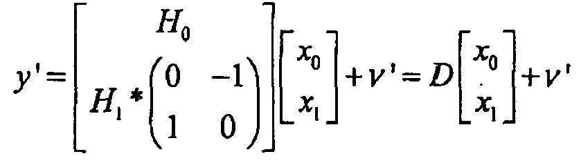
- As it is a linear expression, the MMSE estimation of x is provided simply by:

where DH stands for the Hermitian of D. - For the first variant of Alamouti in frequency, the transmitted vector is equal to:

- Let us define x' by

- Then the transmitted vector is now equal to:

- And the received vector after conjugating the second part as in previous section is now expressed as:

- As it is again a complex linear expression, the MMSE estimation of x' is provided simply by:

and the MMSE estimation of x follows as:
- For the second variant of Alamouti in frequency, the transmitted vector is equal to:

- Let us define x" by

- Then the transmitted vector is now equal to:

- And the received vector after conjugating the second part as in previous section is now expressed as:

- As it is again a complex linear expression, the MMSE estimation of x" is provided simply by:

and the MMSE estimation of x follows as:
-
Fig. 11 illustrates the organigram of the emitting method in the frequency domain according to a particular embodiment of the invention. Step 11.1 is the step of obtaining the N symbols Xk in the frequency domain relatives to data to be transmitted. Step 11.2 is the step of computing the N symbols Yk from the symbols Xk according to formula Yk = ε(-1)k+1 X*M-l-k. Step 11.4 is the step of generating the N, or N' greater than N in the case of zero insertion as already mentioned, said signals to be emitted on the first antenna from the Xk symbols. Step 11.3 is the step of generating the N, or N', said signals yn to be emitted on the second antenna from the Yk symbols. In step 11.6 signals representing the xn symbols are emitted on the first antenna while signals representing the yn symbols are emitted on the second antenna in step 11.5. -
Fig. 12 illustrates the organigram of the receiving method, in the case of one receive antenna, in a particular embodiment of the invention. Step 12.1 is the step of obtaining the N received symbols in the frequency domain relatives to data that have been transmitted. Step 12.2 is the step of applying an Alamouti decoding module on each pair of received signals according to the variant of Alamouti encoding code used by the emitter to encode signals emitted on said pair of frequencies. In a step 12.3 an estimation of xn symbols in time domain is obtained from the above estimated symbols in the frequency domain. - The MIMO scheme described with two antennas can be extended to any even number of antennas. The extension is done by grouping the antenna by pair and to apply one of the coding schemes, as defined in the invention, to each pair of antennas.
- The invention can be applied to any transmission system that will use several transmitters. It is very likely to concern wireless systems; however, it could be used e.g. to line transmissions in which crossover interference would occur. Moreover, it was described in DFT-spread OFDM context. However, any modulation scheme could use the proposed invention, even if a real benefit will only occur for modulations with a constant envelope. Concerning the cyclic prefix, it simplifies the receiver implementation in the frequency domain. However, other frequency domain implementation of the receiver should be possible without it, even if it would be more complex. Examples of such implementation are overlap methods (e.g. overlap-add or overlap-save). In overlap-save method, N samples will be treated in the frequency domain and transform in the time domain, and only some of them will be kept in the time domain. The corresponding treatment windows are overlapping to insure that all the received samples are treated.
Claims (8)
- Method of radio data emission, by an emitter comprising at least two transmit antennas, each antenna transmitting on at least an even number 'N', strictly greater than 4, of different frequencies, comprising the following steps:- a step of emitting on a first antenna during a given time slot on each frequency 'k', with k = 0 to N-1, a signal representing a complex symbol 'Xk' in the frequency domain;- a step of emitting on a second antenna during the same time slot, on each frequency 'k', with k = 0 to N-1, a signal representing a symbol 'Yk ';characterized in that:- for a given integer value M chosen as an even value between 0 and N-1 inclusive, the symbol Yk is derived from the symbols Xk, for each frequency k, by the formula:

where ε is 1 or -1 and X* means the complex conjugate of X and where M-1-k is taken modulo N;
resulting in a pairing of frequencies according to a pairing scheme and applying to each pair of frequencies a variant of an Alamouti code on symbols to be emitted. - Method according to claim 1 characterized in that, N being divisible by 4, the chosen value of M equal to N/2.
- Method according to claim 1 characterized in that, the chosen value of M equal to 0.
- Method according to any of claim 1 to 3 further comprising the step of:- obtaining the N symbols Xk in the frequency domain relatives to data to be transmitted;- computing the N symbols Yk from the symbols Xk according to said formula;- generating the N said signals to be emitted on the first antenna from the Xk symbols;- generating the N said signals to be emitted on the second antenna from the Yk symbols.
- Method according to any of claims 1 to 3 further comprising the step of:- obtaining N symbols xn in the time domain relatives to data to be transmitted;- computing the N symbols yn from the symbols xk according to formula yn = εW(M-1)n x* n-N/2 where W = e j2π/N , where x* stands for the complex conjugate of x, and where n-Nl2 is taken modulo N;- generating the N said signals to be emitted on the first antenna from the xn symbols;- generating the N said signals to be emitted on the second antenna from the yn symbols.
- Method of radio data reception, from a transmitter comprising at least two transmit antennas, of signals on at least an even number of frequencies, said signals being emitted according to Claim 1, characterized in that said method comprises the following steps:- a step of pairing received signals on said frequencies according to the emitting pairing scheme;- a step of applying a space frequency code decoding module on each pair of received signals according to the variant of Alamouti encoding code used by the emitter to encode signals emitted on said pair of frequencies.
- Emitting device comprising:- at least two transmit antennas;- means to transmit on each antenna at least an even number 'N' of different frequencies,- means to emit on a first antenna during a given time slot on each frequency 'k', with k = 0 to N-1, a signal representing a complex symbol 'Xk' in the frequency domain;- means to emit on a second antenna during the same time slot, on each frequency 'k', with k = 0 to N-1, a signal representing a symbol 'Yk';characterized in that:- for a given integer value M chosen between 0 and N-1 inclusive, the symbol Yk is derived from the symbols Xk , for each frequency k, by the formula:

- Receiving device characterized in that it comprises:- means to receive signals on at least an even number of frequencies from a transmitter comprising at least two transmit antennas, said signals being emitted according to claim 1;- means to pair received signals on said frequencies according to the emitting pairing scheme;- means to apply an space frequency code decoding module on each pair of received signals according to the variant of Alamouti encoding code used by the emitter to encode signals emitted on said pair of frequencies.
Priority Applications (21)
| Application Number | Priority Date | Filing Date | Title |
|---|---|---|---|
| EP07003191A EP1959603A1 (en) | 2007-02-15 | 2007-02-15 | Method of radio data emission, emitter and receiver using the method |
| CN2008800049769A CN101669315B (en) | 2007-02-15 | 2008-01-24 | Method of ratio data emission, emitter and receiver using the method |
| KR1020097016952A KR101523392B1 (en) | 2007-02-15 | 2008-01-24 | Wireless data radiating method, radiator and transmitter using the same |
| EP08707265A EP2127179B1 (en) | 2007-02-15 | 2008-01-24 | Method of ratio data emission, emitter and receiver using the method |
| PCT/EP2008/000554 WO2008098667A1 (en) | 2007-02-15 | 2008-01-24 | Method of ratio data emission, emitter and receiver using the method |
| JP2009549367A JP5027255B2 (en) | 2007-02-15 | 2008-01-24 | Ratio data emission method, radiators and receivers using the method |
| US12/526,551 US8233467B2 (en) | 2007-02-15 | 2008-01-24 | Method of ratio data emission, emitter and receiver using the method |
| AT08707275T ATE485645T1 (en) | 2007-02-15 | 2008-01-25 | METHOD FOR WIRELESS DATA TRANSMISSION WITH SEVERAL ANTENNAS AND CORRESPONDING TRANSMITTER AND RECEIVER |
| CN2008800049487A CN101657987B (en) | 2007-02-15 | 2008-01-25 | Method of radio data emission, emitter and receiver using the method |
| PCT/EP2008/000565 WO2008098670A1 (en) | 2007-02-15 | 2008-01-25 | Method of multi-antenna wireless data emission, emitter and receiver using the method |
| US12/526,985 US8270527B2 (en) | 2007-02-15 | 2008-01-25 | SC-QOSTFBC codes for MIMO transmitters |
| JP2009549368A JP5286284B2 (en) | 2007-02-15 | 2008-01-25 | Multi-antenna wireless data transmission method, transmitter and receiver using this method |
| CN2008800052210A CN101715636B (en) | 2007-02-15 | 2008-01-25 | Method for SC-QOSTFBC codes for MIMO transmitters |
| KR1020097016953A KR101434704B1 (en) | 2007-02-15 | 2008-01-25 | Wireless data radiating method, radiator and transmitter using the same |
| DE602008003104T DE602008003104D1 (en) | 2007-02-15 | 2008-01-25 | METHOD FOR WIRELESS DATA TRANSMISSION WITH SEVERAL ANTENNAS AND SUITABLE TRANSMITTER AND RECEIVER |
| KR1020097016954A KR101380021B1 (en) | 2007-02-15 | 2008-01-25 | SCQOSTFBC codes for MIMO transmitters |
| EP08707288.0A EP2122891B1 (en) | 2007-02-15 | 2008-01-25 | Sc-qostfbc codes for mimo transmitters |
| US12/526,849 US8040867B2 (en) | 2007-02-15 | 2008-01-25 | Method of multi-antenna wireless data emission, emitter and receiver using the method |
| EP08707275A EP2127180B1 (en) | 2007-02-15 | 2008-01-25 | Method of multi-antenna wireless data emission, emitter and receiver using the method |
| PCT/EP2008/000578 WO2008098672A1 (en) | 2007-02-15 | 2008-01-25 | Sc-qostfbc codes for mimo transmitters |
| JP2009549369A JP5284284B2 (en) | 2007-02-15 | 2008-01-25 | SC-QOSTFBC code for MIMO transmitter |
Applications Claiming Priority (1)
| Application Number | Priority Date | Filing Date | Title |
|---|---|---|---|
| EP07003191A EP1959603A1 (en) | 2007-02-15 | 2007-02-15 | Method of radio data emission, emitter and receiver using the method |
Publications (1)
| Publication Number | Publication Date |
|---|---|
| EP1959603A1 true EP1959603A1 (en) | 2008-08-20 |
Family
ID=38222387
Family Applications (2)
| Application Number | Title | Priority Date | Filing Date |
|---|---|---|---|
| EP07003191A Withdrawn EP1959603A1 (en) | 2007-02-15 | 2007-02-15 | Method of radio data emission, emitter and receiver using the method |
| EP08707265A Not-in-force EP2127179B1 (en) | 2007-02-15 | 2008-01-24 | Method of ratio data emission, emitter and receiver using the method |
Family Applications After (1)
| Application Number | Title | Priority Date | Filing Date |
|---|---|---|---|
| EP08707265A Not-in-force EP2127179B1 (en) | 2007-02-15 | 2008-01-24 | Method of ratio data emission, emitter and receiver using the method |
Country Status (6)
| Country | Link |
|---|---|
| US (1) | US8233467B2 (en) |
| EP (2) | EP1959603A1 (en) |
| JP (1) | JP5027255B2 (en) |
| KR (1) | KR101523392B1 (en) |
| CN (2) | CN101669315B (en) |
| WO (1) | WO2008098667A1 (en) |
Cited By (4)
| Publication number | Priority date | Publication date | Assignee | Title |
|---|---|---|---|---|
| EP2197138A1 (en) * | 2008-12-15 | 2010-06-16 | Mitsubishi Electric R&D Centre Europe B.V. | Space-frequency block coding for a multiuser system |
| EP2230788A1 (en) * | 2009-03-20 | 2010-09-22 | Mitsubishi Electric R&D Centre Europe B.V. | Method and device for determining a shifting parameter to be used by a telecommunication device for transferring symbols |
| WO2011026235A1 (en) * | 2009-09-02 | 2011-03-10 | Nortel Networks Limited | Transmission of multicast broadcast service (mbs) traffic in a wireless environment |
| JP2011510519A (en) * | 2007-02-15 | 2011-03-31 | ミツビシ・エレクトリック・アールアンドディー・センター・ヨーロッパ・ビーヴィ | SC-QOSTFBC code for MIMO transmitter |
Families Citing this family (17)
| Publication number | Priority date | Publication date | Assignee | Title |
|---|---|---|---|---|
| EP2266219A4 (en) * | 2008-03-27 | 2013-01-23 | Korea Electronics Telecomm | CODE-DIVISION MULTIPLEXING MULTI-CARRIER WIRELESS COMMUNICATION APPARATUS USING AN EMISSION DIVERSITY SCHEME |
| KR20100019947A (en) | 2008-08-11 | 2010-02-19 | 엘지전자 주식회사 | Method of transmitting information in wireless communication system |
| KR101603338B1 (en) * | 2008-08-11 | 2016-03-15 | 엘지전자 주식회사 | Method and apparatus of transmitting information in wireless communication system |
| KR101571566B1 (en) | 2008-08-11 | 2015-11-25 | 엘지전자 주식회사 | Method of transmitting control signal in wireless communication system |
| KR101243508B1 (en) * | 2008-11-14 | 2013-03-20 | 엘지전자 주식회사 | Method and apparatus for signal transmission in wireless communication system |
| WO2010056078A2 (en) | 2008-11-14 | 2010-05-20 | 엘지전자주식회사 | Method and apparatus for information transmission in wireless communication system |
| KR20100091876A (en) | 2009-02-11 | 2010-08-19 | 엘지전자 주식회사 | Ue behavior for multi-antenna transmission |
| CN102685046B (en) * | 2012-05-02 | 2015-02-11 | 合肥东芯通信股份有限公司 | Equalizing device and equalizing method in transmission diversity mode of LTE (long term evolution) system |
| US9755722B2 (en) | 2014-08-07 | 2017-09-05 | Mitsubishi Electric Corporation | Transmission device, reception device, communication system, transmission method and reception method |
| CN105322991B (en) * | 2015-10-15 | 2018-10-02 | 哈尔滨工业大学 | MIMO transmission system and transmission method based on WFRFT precodings |
| WO2017155320A1 (en) * | 2016-03-09 | 2017-09-14 | 엘지전자 주식회사 | Method for transmitting and receiving signals in v2x communication, and apparatus therefor |
| JP6965335B2 (en) * | 2016-09-28 | 2021-11-10 | オッポ広東移動通信有限公司Guangdong Oppo Mobile Telecommunications Corp., Ltd. | Data transmission method, receiving device and transmitting device |
| US10063306B2 (en) * | 2016-10-24 | 2018-08-28 | Mitsubishi Electric Research Laboratories, Inc. | Method and systems using quasi-synchronous distributed CDD systems |
| EP3435609B1 (en) | 2017-07-25 | 2022-12-07 | Mitsubishi Electric R&D Centre Europe B.V. | Pre-dft reference signal insertion for sc-sfbc |
| WO2020026450A1 (en) * | 2018-08-03 | 2020-02-06 | 株式会社Nttドコモ | User terminal |
| US11159226B2 (en) * | 2019-08-27 | 2021-10-26 | Kookmin University Industry Academy Cooperation Foundation | Method and apparatus for implementing transmission diversity using single transmitter |
| US20240113818A1 (en) * | 2022-10-03 | 2024-04-04 | Telefonaktiebolaget Lm Ericsson (Publ) | Waveform for wireless signalling |
Citations (4)
| Publication number | Priority date | Publication date | Assignee | Title |
|---|---|---|---|---|
| WO2004038987A2 (en) * | 2002-10-25 | 2004-05-06 | Qualcomm, Incorporated | Transmit diversity processing for a multi-antenna communication system |
| EP1496658A1 (en) * | 2003-07-08 | 2005-01-12 | Samsung Electronics Co., Ltd. | System and method for channel estimation in an OFDM mobile communication system |
| EP1548970A1 (en) * | 2003-12-24 | 2005-06-29 | Samsung Electronics Co., Ltd. | Apparatus for transmitting space-time/space-frequency block coded data in an OFDM communication system and method thereof |
| US20060078066A1 (en) * | 2004-10-11 | 2006-04-13 | Samsung Electronics Co., Ltd. | Apparatus and method for minimizing a PAPR in an OFDM communication system |
Family Cites Families (10)
| Publication number | Priority date | Publication date | Assignee | Title |
|---|---|---|---|---|
| JP2002344415A (en) * | 2001-05-14 | 2002-11-29 | Matsushita Electric Ind Co Ltd | Multi-carrier communication method and multi-carrier communication device |
| JP3962020B2 (en) * | 2001-11-10 | 2007-08-22 | サムスン エレクトロニクス カンパニー リミテッド | Spatio-temporal-frequency encoding / decoding apparatus and method in orthogonal frequency division multiplexing mobile communication system |
| US7440510B2 (en) * | 2003-09-15 | 2008-10-21 | Intel Corporation | Multicarrier transmitter, multicarrier receiver, and methods for communicating multiple spatial signal streams |
| KR100754795B1 (en) * | 2004-06-18 | 2007-09-03 | 삼성전자주식회사 | Apparatus and method for encoding / decoding of frequency space block codes in orthogonal frequency division multiplexing system |
| JP4436415B2 (en) * | 2004-08-17 | 2010-03-24 | サムスン エレクトロニクス カンパニー リミテッド | Spatio-temporal frequency block coding apparatus and method for improving performance |
| KR100938091B1 (en) * | 2004-10-13 | 2010-01-21 | 삼성전자주식회사 | Base Station Transmission Apparatus and Method Using Block Coding Technique and Cyclic Delay Diversity Technique in Orthogonal Frequency Multiplexing Mobile Communication System |
| KR100719840B1 (en) * | 2004-11-04 | 2007-05-18 | 삼성전자주식회사 | Space-time frequency block encoding apparatus and method |
| CN1801665A (en) * | 2005-01-07 | 2006-07-12 | 三星电子株式会社 | Apparatus and method for space-time-frequency block coding in a wireless communication system |
| KR100950639B1 (en) * | 2005-03-23 | 2010-04-01 | 삼성전자주식회사 | Transmission and reception apparatus and method using frequency space block coding technique and single carrier frequency domain equalization |
| JP5284284B2 (en) * | 2007-02-15 | 2013-09-11 | ミツビシ・エレクトリック・アールアンドディー・センター・ヨーロッパ・ビーヴィ | SC-QOSTFBC code for MIMO transmitter |
-
2007
- 2007-02-15 EP EP07003191A patent/EP1959603A1/en not_active Withdrawn
-
2008
- 2008-01-24 JP JP2009549367A patent/JP5027255B2/en not_active Expired - Fee Related
- 2008-01-24 US US12/526,551 patent/US8233467B2/en not_active Expired - Fee Related
- 2008-01-24 CN CN2008800049769A patent/CN101669315B/en not_active Expired - Fee Related
- 2008-01-24 WO PCT/EP2008/000554 patent/WO2008098667A1/en not_active Ceased
- 2008-01-24 KR KR1020097016952A patent/KR101523392B1/en not_active Expired - Fee Related
- 2008-01-24 EP EP08707265A patent/EP2127179B1/en not_active Not-in-force
- 2008-01-25 CN CN2008800049487A patent/CN101657987B/en not_active Expired - Fee Related
Patent Citations (4)
| Publication number | Priority date | Publication date | Assignee | Title |
|---|---|---|---|---|
| WO2004038987A2 (en) * | 2002-10-25 | 2004-05-06 | Qualcomm, Incorporated | Transmit diversity processing for a multi-antenna communication system |
| EP1496658A1 (en) * | 2003-07-08 | 2005-01-12 | Samsung Electronics Co., Ltd. | System and method for channel estimation in an OFDM mobile communication system |
| EP1548970A1 (en) * | 2003-12-24 | 2005-06-29 | Samsung Electronics Co., Ltd. | Apparatus for transmitting space-time/space-frequency block coded data in an OFDM communication system and method thereof |
| US20060078066A1 (en) * | 2004-10-11 | 2006-04-13 | Samsung Electronics Co., Ltd. | Apparatus and method for minimizing a PAPR in an OFDM communication system |
Cited By (11)
| Publication number | Priority date | Publication date | Assignee | Title |
|---|---|---|---|---|
| JP2011510519A (en) * | 2007-02-15 | 2011-03-31 | ミツビシ・エレクトリック・アールアンドディー・センター・ヨーロッパ・ビーヴィ | SC-QOSTFBC code for MIMO transmitter |
| EP2197138A1 (en) * | 2008-12-15 | 2010-06-16 | Mitsubishi Electric R&D Centre Europe B.V. | Space-frequency block coding for a multiuser system |
| US8306141B2 (en) | 2008-12-15 | 2012-11-06 | Mitsubishi Electric Corporation | Method and a device for determining shifting parameters to be used by at least a first and a second telecommunication devices |
| CN101917258B (en) * | 2008-12-15 | 2014-05-28 | 三菱电机株式会社 | Method and apparatus for determining a shift parameter to be used by a telecommunication device |
| EP2230788A1 (en) * | 2009-03-20 | 2010-09-22 | Mitsubishi Electric R&D Centre Europe B.V. | Method and device for determining a shifting parameter to be used by a telecommunication device for transferring symbols |
| WO2010105973A1 (en) * | 2009-03-20 | 2010-09-23 | Mitsubishi Electric R&D Centre Europe B.V. | Method and a device for determining a shifting parameter to be used by a telecommunication device for transferring symbols |
| CN102356587A (en) * | 2009-03-20 | 2012-02-15 | 三菱电机研发中心欧洲有限公司 | Method and device for determining an offset parameter to be used by a telecommunication device for transmitting symbols |
| US8913569B2 (en) | 2009-03-20 | 2014-12-16 | Mitsubishi Electric Corporation | Method and a device for determining a shifting parameter to be used by a telecommunication device for transferring symbols |
| CN102356587B (en) * | 2009-03-20 | 2014-12-17 | 三菱电机研发中心欧洲有限公司 | Method and apparatus for determining offset parameters to be used by telecommunication equipment to transmit symbols |
| WO2011026235A1 (en) * | 2009-09-02 | 2011-03-10 | Nortel Networks Limited | Transmission of multicast broadcast service (mbs) traffic in a wireless environment |
| RU2553677C2 (en) * | 2009-09-02 | 2015-06-20 | Эппл Инк | Method of transmitting multicast and broadcast service (mbs) traffic in wireless communication system |
Also Published As
| Publication number | Publication date |
|---|---|
| CN101657987A (en) | 2010-02-24 |
| EP2127179A1 (en) | 2009-12-02 |
| WO2008098667A1 (en) | 2008-08-21 |
| KR101523392B1 (en) | 2015-05-27 |
| US8233467B2 (en) | 2012-07-31 |
| JP2010518767A (en) | 2010-05-27 |
| US20100040164A1 (en) | 2010-02-18 |
| EP2127179B1 (en) | 2012-09-05 |
| CN101669315B (en) | 2013-06-12 |
| JP5027255B2 (en) | 2012-09-19 |
| CN101669315A (en) | 2010-03-10 |
| CN101657987B (en) | 2013-02-06 |
| KR20090115792A (en) | 2009-11-06 |
Similar Documents
| Publication | Publication Date | Title |
|---|---|---|
| EP2127179B1 (en) | Method of ratio data emission, emitter and receiver using the method | |
| EP2127180B1 (en) | Method of multi-antenna wireless data emission, emitter and receiver using the method | |
| US8111772B2 (en) | Method and apparatus for multi-antenna transmitting based on spatial-frequency encoding | |
| KR101543291B1 (en) | Apparatus and method for antenna mapping in a mimo wireless communication system | |
| EP1628426B1 (en) | Apparatus and method for space-time-frequency block coding for increasing performance | |
| US20060227891A1 (en) | Method of channel estimation for MIMO-OFDM using phase rotated low overhead preamble | |
| KR101345351B1 (en) | Method and apparatus of space-time-frequency coding | |
| US20090310687A1 (en) | Method and apparatus for space-time-frequency encoding and decoding | |
| EP1661346B1 (en) | Apparatus and method for providing a multi-carrier signal to be transmitted and apparatus and method for providing an output signal from a received multi-carrier signal | |
| CN101257468B (en) | Method and device for mapping and inverse mapping sub-carrier wave modulated by multi-carrier waves | |
| EP1976173A1 (en) | Method of multi-antenna wireless data emission, emitter and receiver using the method | |
| EP2409442B1 (en) | Method and device for determining a shifting parameter to be used by a telecommunication device for transferring symbols | |
| Wang et al. | Spatial division multiplexing of space time block codes for single carrier block transmission |
Legal Events
| Date | Code | Title | Description |
|---|---|---|---|
| PUAI | Public reference made under article 153(3) epc to a published international application that has entered the european phase |
Free format text: ORIGINAL CODE: 0009012 |
|
| AK | Designated contracting states |
Kind code of ref document: A1 Designated state(s): AT BE BG CH CY CZ DE DK EE ES FI FR GB GR HU IE IS IT LI LT LU LV MC NL PL PT RO SE SI SK TR |
|
| AX | Request for extension of the european patent |
Extension state: AL BA HR MK RS |
|
| 17P | Request for examination filed |
Effective date: 20081020 |
|
| 17Q | First examination report despatched |
Effective date: 20081124 |
|
| RAP1 | Party data changed (applicant data changed or rights of an application transferred) |
Owner name: MITSUBISHI ELECTRIC CORPORATION Owner name: MITSUBISHI ELECTRIC R&D CENTRE EUROPE B.V. |
|
| AKX | Designation fees paid |
Designated state(s): AT BE BG CH CY CZ DE DK EE ES FI FR GB GR HU IE IS IT LI LT LU LV MC NL PL PT RO SE SI SK TR |
|
| STAA | Information on the status of an ep patent application or granted ep patent |
Free format text: STATUS: THE APPLICATION IS DEEMED TO BE WITHDRAWN |
|
| 18D | Application deemed to be withdrawn |
Effective date: 20090407 |