EP1959315A1 - Air knife system with pressure sensor - Google Patents
Air knife system with pressure sensor Download PDFInfo
- Publication number
- EP1959315A1 EP1959315A1 EP08101363A EP08101363A EP1959315A1 EP 1959315 A1 EP1959315 A1 EP 1959315A1 EP 08101363 A EP08101363 A EP 08101363A EP 08101363 A EP08101363 A EP 08101363A EP 1959315 A1 EP1959315 A1 EP 1959315A1
- Authority
- EP
- European Patent Office
- Prior art keywords
- pressure
- sheet
- gas
- control system
- valve
- Prior art date
- Legal status (The legal status is an assumption and is not a legal conclusion. Google has not performed a legal analysis and makes no representation as to the accuracy of the status listed.)
- Granted
Links
- 230000037361 pathway Effects 0.000 claims abstract description 22
- 239000012530 fluid Substances 0.000 claims abstract description 18
- 239000000463 material Substances 0.000 claims abstract description 9
- 238000000034 method Methods 0.000 claims description 31
- 238000007639 printing Methods 0.000 description 16
- 230000004044 response Effects 0.000 description 12
- 230000008569 process Effects 0.000 description 11
- 238000011144 upstream manufacturing Methods 0.000 description 8
- 238000009530 blood pressure measurement Methods 0.000 description 6
- 238000001816 cooling Methods 0.000 description 6
- 238000005259 measurement Methods 0.000 description 6
- 108091008695 photoreceptors Proteins 0.000 description 6
- 230000008859 change Effects 0.000 description 5
- 230000009471 action Effects 0.000 description 4
- 238000004891 communication Methods 0.000 description 3
- 239000000976 ink Substances 0.000 description 3
- 238000012545 processing Methods 0.000 description 2
- 238000009877 rendering Methods 0.000 description 2
- 238000012546 transfer Methods 0.000 description 2
- 239000004809 Teflon Substances 0.000 description 1
- 230000000712 assembly Effects 0.000 description 1
- 238000000429 assembly Methods 0.000 description 1
- 238000005452 bending Methods 0.000 description 1
- 238000007664 blowing Methods 0.000 description 1
- 239000000919 ceramic Substances 0.000 description 1
- 238000004140 cleaning Methods 0.000 description 1
- 239000011248 coating agent Substances 0.000 description 1
- 238000000576 coating method Methods 0.000 description 1
- 239000003086 colorant Substances 0.000 description 1
- 230000001010 compromised effect Effects 0.000 description 1
- 239000013256 coordination polymer Substances 0.000 description 1
- 230000001934 delay Effects 0.000 description 1
- 238000006073 displacement reaction Methods 0.000 description 1
- 230000000694 effects Effects 0.000 description 1
- 239000008187 granular material Substances 0.000 description 1
- 238000003384 imaging method Methods 0.000 description 1
- 230000000977 initiatory effect Effects 0.000 description 1
- 239000007788 liquid Substances 0.000 description 1
- 239000002184 metal Substances 0.000 description 1
- 239000000203 mixture Substances 0.000 description 1
- 238000012986 modification Methods 0.000 description 1
- 230000004048 modification Effects 0.000 description 1
- 239000002245 particle Substances 0.000 description 1
- 239000004033 plastic Substances 0.000 description 1
- 230000002028 premature Effects 0.000 description 1
- 230000000717 retained effect Effects 0.000 description 1
- 229910052594 sapphire Inorganic materials 0.000 description 1
- 239000010980 sapphire Substances 0.000 description 1
- 238000000926 separation method Methods 0.000 description 1
- 229920002545 silicone oil Polymers 0.000 description 1
- 239000007787 solid Substances 0.000 description 1
- 239000000758 substrate Substances 0.000 description 1
- 230000003746 surface roughness Effects 0.000 description 1
- 238000004381 surface treatment Methods 0.000 description 1
- 230000002123 temporal effect Effects 0.000 description 1
Images



Classifications
-
- G—PHYSICS
- G03—PHOTOGRAPHY; CINEMATOGRAPHY; ANALOGOUS TECHNIQUES USING WAVES OTHER THAN OPTICAL WAVES; ELECTROGRAPHY; HOLOGRAPHY
- G03G—ELECTROGRAPHY; ELECTROPHOTOGRAPHY; MAGNETOGRAPHY
- G03G15/00—Apparatus for electrographic processes using a charge pattern
- G03G15/20—Apparatus for electrographic processes using a charge pattern for fixing, e.g. by using heat
- G03G15/2003—Apparatus for electrographic processes using a charge pattern for fixing, e.g. by using heat using heat
- G03G15/2014—Apparatus for electrographic processes using a charge pattern for fixing, e.g. by using heat using heat using contact heat
- G03G15/2017—Structural details of the fixing unit in general, e.g. cooling means, heat shielding means
- G03G15/2028—Structural details of the fixing unit in general, e.g. cooling means, heat shielding means with means for handling the copy material in the fixing nip, e.g. introduction guides, stripping means
-
- G—PHYSICS
- G03—PHOTOGRAPHY; CINEMATOGRAPHY; ANALOGOUS TECHNIQUES USING WAVES OTHER THAN OPTICAL WAVES; ELECTROGRAPHY; HOLOGRAPHY
- G03G—ELECTROGRAPHY; ELECTROPHOTOGRAPHY; MAGNETOGRAPHY
- G03G2215/00—Apparatus for electrophotographic processes
- G03G2215/00025—Machine control, e.g. regulating different parts of the machine
- G03G2215/00029—Image density detection
- G03G2215/00067—Image density detection on recording medium
-
- G—PHYSICS
- G03—PHOTOGRAPHY; CINEMATOGRAPHY; ANALOGOUS TECHNIQUES USING WAVES OTHER THAN OPTICAL WAVES; ELECTROGRAPHY; HOLOGRAPHY
- G03G—ELECTROGRAPHY; ELECTROPHOTOGRAPHY; MAGNETOGRAPHY
- G03G2215/00—Apparatus for electrophotographic processes
- G03G2215/00362—Apparatus for electrophotographic processes relating to the copy medium handling
- G03G2215/00535—Stable handling of copy medium
- G03G2215/00548—Jam, error detection, e.g. double feeding
-
- G—PHYSICS
- G03—PHOTOGRAPHY; CINEMATOGRAPHY; ANALOGOUS TECHNIQUES USING WAVES OTHER THAN OPTICAL WAVES; ELECTROGRAPHY; HOLOGRAPHY
- G03G—ELECTROGRAPHY; ELECTROPHOTOGRAPHY; MAGNETOGRAPHY
- G03G2215/00—Apparatus for electrophotographic processes
- G03G2215/00362—Apparatus for electrophotographic processes relating to the copy medium handling
- G03G2215/00535—Stable handling of copy medium
- G03G2215/00717—Detection of physical properties
- G03G2215/00721—Detection of physical properties of sheet position
Definitions
- the exemplary embodiment relates to the imaging arts. It finds particular application in connection with an air knife stripping system for a fuser assembly and will be described with particular reference thereto.
- a marking engine in typical electrostatographic printing systems, for example, such as copy machines and laser beam printers, includes a photoconductive insulating member, such as a photoreceptor belt or drum, which is charged to a uniform potential and thereafter exposed to a light image of an original document to be reproduced. The exposure discharges the photoconductive insulating surface in exposed or background areas and creates an electrostatic latent image on the member, which corresponds to the image areas contained within the document. Subsequently, the electrostatic latent image on the photoconductive insulating surface is made visible by developing the image with a marking material.
- the marking material comprises toner particles adhering triboelectrically to carrier granules, which is often referred to simply as toner.
- the developed image is subsequently transferred to the print medium, such as a sheet of paper. The fusing of the toner image onto paper is generally accomplished by a fuser which applies heat to the toner with a heated fuser roll and application of pressure.
- the molten toner has a tendency to stick to the elastomeric surface of the heated fuser roll, especially in the case of rolls with oiled or oil-releasing surfaces.
- Various types of stripping systems have been developed.
- jets of air are directed towards the print media to separate the print media from the fuser roll.
- the jets are emitted from small holes in an elongate surface which extends adjacent the fuser roll.
- the air jets have a tendency to lower the surface temperature of the fuser roll adjacent the jet, which can result in uneven gloss across the print media.
- systems have been developed which apply a short burst of air just as the leading edge of the print media reaches the air knife to initiate separation.
- a fusing assembly includes a fuser member which, during operation, contacts a sheet of print media to fuse a marking material to the sheet.
- a stripping apparatus applies gas to the sheet to assist in detaching the sheet from the fuser member.
- the stripping apparatus includes a fluid pathway which connects an associated source of pressurized gas with at least one orifice adjacent the fuser member.
- a pressure sensor senses a pressure of the gas in the fluid pathway intermediate the source and the at least one orifice during operation of the fuser member.
- the fusing assembly further comprises a control system which receives pressure-related signals from the pressure sensor.
- control system determines whether a fault condition exists in the fusing assembly based at least in part on the pressure-related signals.
- control system determines whether the pressure of the gas is outside a predetermined range based on the pressure-related signals.
- control system determines an adjustment to the stripping apparatus based on the pressure-related signals.
- control system is configured for controlling actuation of at least one of a valve and a pressure regulator in the fluid pathway based on the pressure-related signals.
- the at least one valve comprises a solenoid valve which is selectively actuated to provide a pulse of gas to the at least one orifice.
- control system is configured for issuing a notification of a fault condition based on the pressure-related signals.
- the fusing assembly further comprises a second sensor and wherein the control system determines a fault condition or an adjustment to the stripping apparatus based on information from the first and second sensors.
- the fluid pathway includes at least one selectively actuatable valve and the pressure sensor is intermediate the at least one selectively actuatable valve and the orifices.
- the orifice includes a plurality of orifices which communicate with a plenum and the pressure sensor senses the gas pressure in the plenum.
- the fuser member comprises a rotatable roll.
- the pressure sensor comprises a pressure transducer.
- a xerographic printing system includes the fusing assembly.
- a method in another aspect, includes contacting a sheet of print media with a fuser member to fuse a marking material to the sheet. A gas is applied toward the sheet to assist in detaching the sheet from the fuser member. The method further includes sensing a pressure of the gas being applied to the sheet.
- the applying of the gas includes, for each of a plurality of the sheets, applying gas at a first pressure for a first period of time and applying the gas at a second pressure for a second period of time and wherein the sensing of the pressure includes sensing the pressure of the gas in at least one of the first and second periods of time.
- the method further comprises determining whether a fault condition exists based on the sensed pressure.
- the method when a fault condition is determined to exist, includes automatically initiating a computer implemented process.
- the method further comprises adjusting at least one of a valve and a regulator to modify a flow rate of the gas if the sensed pressure is outside a selected range.
- the applying of the gas includes applying a pulse of gas to a leading edge of the sheet and wherein the sensing of the pressure of the gas includes sensing the pressure at least once during the pulse.
- the applying a pulse includes opening and closing at least one valve in a fluid supply pathway carrying the pressurized gas and wherein the method further includes, based on the at least one sensed pressure, modifying at least one of: a length of time that the valve is in an open position during a pulse of gas, a position of the valve between open and closed positions during the pulse, and a time at which the valve is opened.
- a fusing assembly in another aspect, includes a fuser and a stripping apparatus.
- the stripping apparatus includes a pneumatic airflow system including at least one valve which is selectively actuated to deliver a pulse of air to orifices positioned adjacent the fuser and a sensor in communication with the airflow system intermediate the at least one valve and the orifices.
- the sensor generates signals in response to pressure changes in the airflow system.
- a control system receives the signals from the sensor and determines whether a fault condition exists in the fusing assembly based on the signals.
- aspects of the exemplary embodiment relate to a stripping apparatus for stripping sheets from a fuser member, such as a heated roll of a fuser, to a fusing assembly incorporating the stripping apparatus, and to a method of printing.
- a fuser member such as a heated roll of a fuser
- the exemplary stripping apparatus includes an air knife and a pneumatic airflow system which supplies the air knife with pressurized air, or other suitable gas or gas mixture. It has been found that in a conventional air knife system, the air flow can vary over time, due, for example, to leaks, blockages, or the like in the pneumatic system. As a consequence, the airflow at the jets may diminish, leading to inadequate stripping of the paper from the fuser roll. This, in turn, can lead to image quality problems and paper jams. However, another factor in the quality of stripping is the wear on the fuser. If the fuser roll is already worn, increasing the airflow may thus not cure the problem, and in some cases, may exacerbate it.
- a pressure sensor senses the air pressure at the knife. Based on the sensed pressure, a control system may implement a computer implemented process, such as a request for a service call or adjustments to the airflow system.
- a "printing system,” as used herein, can include any device for rendering an image on print media, such as a copier, printer, bookmaking machine, facsimile machine, or a multifunction machine.
- a printing system may include at least one marking engine which includes components for rendering an image on print media and a fusing assembly for fixing the image to the print media.
- Exemplary marking engines include xerographic marking engines, although inkjet marking engines are also contemplated, such as those which employ heat-curable inks or "solid" inks (inks which are heated to a liquid state prior to marking and which solidify again on cooling).
- Print media can be a usually flimsy physical sheet of paper, plastic, or other suitable physical print media substrate for images.
- An image generally may include information in electronic form which is to be rendered on the print media by the printing system and may include text, graphics, pictures, and the like.
- the operation of applying images to print media, for example, graphics, text, photographs, etc., is generally referred to herein as printing.
- FIGURE 1 a schematic elevational view of electrophotographic (e.g., xerographic) printer, which incorporates the exemplary stripping apparatus, is shown.
- a document 10 to be printed such as an electronic document or a scanned hardcopy, is transmitted as electrical signals from an image input device 11, such as a scanner, computer, or the like to a processing component 12 of the printing system (e.g., a digital front end).
- the processing component 12 converts the digital image into a form in which it can be rendered by a marking engine 14.
- the marking engine 14 includes an image applying component 15, which applies a toner image to sheets 16 of print media conveyed by a conveyor system 17 on a print media path in the direction of arrow A.
- the marked sheets 16, with a toner image thereon, are conveyed to a fuser assembly 18.
- the fuser assembly includes a fuser 19, which applies heat and pressure to fix the toner image more permanently to the sheet, and a stripping apparatus 20 which assists in removing the fused sheets from the fuser.
- the sheets 16 to be marked are fed from a feeder 22, upstream of the marking engine 14 and the marked sheets are delivered by the conveyor system to a finisher 24, downstream of the fuser 19, herein illustrated as paper trays.
- the stripping apparatus 20, and optionally other components of the printing system, including the image applying component 15, fuser 19, and conveyor system 17, may be under the control of a control system 26, which controls the operation of printing.
- FIGURE 1 is a simplified representation of a printer and that additional components, such as inverters, additional marking engines, decurlers, and the like may be incorporated into the print media path.
- the image applying component 15 may include a variety of subcomponents employed in the creation of desired images by electrophotographic processes.
- the image applying component of the marking engine typically includes a charge retentive surface, such as a rotating photoreceptor 30 in the form of a belt or drum. The images are created on a surface of the photoreceptor.
- xerographic subsystems Disposed at various points around the circumference of the photoreceptor 30 are xerographic subsystems which include a cleaning device generally indicated as 32, a charging station for each of the colors to be applied (one in the case of a monochrome printer, four in the case of a CMYK printer), such as a charging corotron 34, an exposure station 36, which forms a latent image on the photoreceptor, such as a raster output scanner, a developer unit 38, associated with each charging station for developing the latent image formed on the surface of the photoreceptor by applying a toner to obtain a toner image, and a transferring unit 40, such as a transfer corotron which transfers the toner image thus formed to the surface of a sheet of print media 16.
- a cleaning device generally indicated as 32
- a charging station for each of the colors to be applied one in the case of a monochrome printer, four in the case of a CMYK printer
- a charging corotron 34 Disposed
- the fuser 19 receives the marked print media with the toner thereon and applies heat and pressure to fuse the image to the sheet.
- the illustrated fuser 19 includes a pair of rotating rolls 44, 46, which together define a nip 48 through which the sheet with the toner image thereon passes. At least one of the rolls 44 is heated, for example, by means of an internal heater 50, such as a lamp. The other roll 46 applies pressure at the nip 48 and in one embodiment, may also be heated.
- the fuser roll 44 has an elastomeric surface 52 to which a thin coating of a release oil, such as silicone oil, may be applied.
- the surface 52 may be provided by a layer of Teflon TM or similar material, which is supported on a cylindrical metal core. While particular reference is made to a rotating fuser roll, other fuser members, such as belts, are also contemplated.
- the exemplary stripping apparatus 20 includes an air knife 54 which is positioned downstream of the nip 48.
- a stripping edge 56 of the air knife 54 is positioned closely adjacent to, but without touching, the fuser roll surface 52.
- Spaced along the edge are a plurality of orifices 58 which direct air jets toward the toner side 60 of a leading edge 62 of the sheet to detach the leading edge of the sheet from the fuser roll 44.
- the orifices 58 are fed with air from a plenum 64 within the air knife 54.
- An underside 66 of the air knife may provide a guiding surface for the sheet.
- the plenum 64 has its longest dimension arranged in the cross-process direction, with the orifices 58 communicating with the plenum via individual air supply tubes 68 formed in a wall of the air knife which defines the edge 56. While multiple collinear orifices 58 feeding air in generally the same orientation from the plenum 64 are shown, it is also contemplated that other arrangements of orifices may be provided, or even that a single laterally extending orifice may be used.
- a pneumatic system 70 supplies air under positive pressure to the plenum 66.
- the pneumatic system 70 includes a source 72 of pressurized air, such as a compressor.
- the pressurized air may be stored temporarily in an accumulator 74 in communication with the compressor 72.
- the plenum 64 forms a part of a fluid pathway 76, which carries the air from the accumulator 74 to the air knife orifices 58.
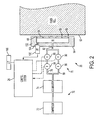
- the fluid pathway 76 in the embodiment illustrated in FIGURE 2 , includes two branch pathways 78, 80, which split the air stream into two streams, however, in other embodiments, a single pathway, or more than two branch pathways, may be employed.
- the two branch pathways 78, 80 rejoin to form an inlet pathway 82, closer to the plenum 64.
- Each branch pathway 78, 80 includes a pressure regulator 84, 86 and a valve 88, 90, downstream of the respective regulator.
- the first regulator 84 may be set at the same or a higher pressure than the second regulator 86.
- the regulators 84, 86 maintain a pressure differential between the portion of the respective branch 78, 80 upstream of the regulator and the portion downstream.
- the regulators 84, 86 may include automated actuators which are actuated by the control system 26, in order to change the pressure differential.
- the valves 88, 90 are automatically actuable valves, such as solenoid valves.
- the solenoid valves 88, 90 are configured for opening and closing briefly, to provide a short burst of air, or pulse.
- the valves 88, 90 are under the control of the control system 26.
- the airflow follows a cycle which is repeated periodically, with each approaching sheet.
- a leading edge 62 of a sheet is approaching the orifices 58
- a burst of air is delivered by opening both valves 88, 90.
- the higher pressure regulator 84, in line with valve 88 is solely responsible for the amount of flow.
- the pressure in the plenum may be at a first pressure P 1 .
- valve 88 may be closed.
- Valve 90 remains open to provide a flow of air which is lower than the initial flow.
- valve 90 After the sheet either passes the orifices 58 completely, or is captured by the next downstream conveyance device, valve 90 also closed, thereby rapidly reducing the pressure to approximately atmospheric.
- the amount of air applied from the orifices 58 is rapidly reduced, first to an intermediate pressure level P 2 , then to zero (approximately atmospheric), as the weight of the fused sheet 16 exiting the nip 48 takes over the role of stripping the sheet from the fuser roll 44.
- the cycle is repeated for each sheet of print media passing through the nip 48.
- valves 88, 90 may be opened at time to, which may be about 20 milliseconds before the lead edge of a sheet reaches the orifices.
- Pressure P 1 may be maintained until time t 1 , which may be about 40 milliseconds after lead edge passes the orifices.
- pressure P 2 may be maintained until t 2 , which may be about 200 milliseconds after the lead edge passes the orifices.
- the fluid pathways 78, 80, 82, etc., which feed the plenum 64 with air may be defined by air hoses which are sealed at connections with the valves 88, 90, regulators 84, 86 and each other by o-rings and the like. Some or all of the air hoses may be formed from rubber or other flexible material. Over time, the rubber may perish or the seals or valves may wear leading to leakage from the fluid lines downstream of the regulators 84, 86. As a result, the airflow at the orifices 58 in each cycle may change over time. The stripping action of the air knife 52 may thus be compromised.
- leading edge 62 of the sheet may be retained on the fuser roll 44 downstream of the nip area, or a portion of the sheet upstream of the leading edge may be reattached to the fuser roll 44 in a process known as retack. Either of these events may lead to differential gloss streaks in the process direction of the toner image.
- the airflow at the orifices 58 may be higher than that planned, leading to cross-process direction variation in gloss due to differential cooling.
- a pressure sensor (PT) 100 is positioned to sense the pressure of the air in the fluid pathway 76 downstream of all the valves 88, 90, i.e., between the valves 88, 90 and the orifices 58. More specifically, the sensor 100 measures a property, such as a diaphragm movement, which changes in response to pressure changes, and outputs a signal, such as a current signal, indicative of the change in the property.
- the pressure sensor senses the pressure in the plenum 64.
- the pressure sensor 100 is tapped into a wall 102 of the air knife at an upstream side of the plenum 64 to provide a fluid passage 104 between the plenum 64 and the pressure sensor 100.
- the pressure transducer may be located adjacent this orifice.
- the pressure sensor 100 may be positioned to measure the pressure in inlet portion 82 or elsewhere downstream of the valves 88, 90.
- a plurality of pressure sensors spaced between the valves 88, 90 and the orifices 58 may be provided.
- the pressure sensor 100 may be a fast response pressure sensor, such as a pressure transducer.
- the pressure transducer 100 may have a response time which is shorter than the time t between opening and closing of the valves.
- the transducer has a response time of less than about 20 milliseconds, e.g., the response time is about 10 milliseconds or less.
- the response time of the pressure sensor 100 is less than the actuation time of the valves 88, 90.
- the valves may take 15 milliseconds or less to actuate.
- the response time of the pressure sensor 100 may be about 100 microseconds, or less, e.g., about 20 microseconds, or less.
- Exemplary pressure sensors are fast response pressure transducers, such as silicon-on-sapphire transducers, as described, for example, in U.S. Patent No. 6,424,017 .
- Pressure transducers of this type may have a response time in the microsecond or nanosecond range and are available from Sensonetics, Inc.
- One example is the SEN-300.
- Capacitative transducers may also be used in this application.
- An exemplary capacitative pressure transducer 100 is a Sensata 61 CP Series or 67CP Series ceramic capacitative pressure sensor which has a maximum response time of 10 milliseconds.
- the pressure sensor 100 provides signals representative of the sensed pressure to the control system 26. For example, current signals representative of pressure changes are output to control system 26.
- the pneumatic airflow system supplies air to the orifices 58 by selective opening and closing of valves 88, 90.
- the air is emitted towards the leading edge to provide a bearing force which separates the sheet 16 from the fuser roll.
- the sensor measures pressure within the plenum and provides a control signal to the control system. If the control system detects a fault condition based on the detected pressure, the control system may implement the computer implemented process.
- the control system 26 determines whether the sensed pressure is within a predetermined acceptable range. For example, the control system may access a look up table (LUT) 106 which stores the predetermined values. Since the pressures sensed by the sensor 100 may change cyclically, as the pressure changes in the plenum 64 throughout a cycle, the control system 26 may compare sensed pressure measurements at various times throughout a cycle to determine whether the sensed pressures are each within a predetermined acceptable range. Alternatively, the control system 26 may compute an average pressure over a cycle, or over multiple cycles, and compared the result to the stored values.
- LUT look up table
- control system may evaluate whether changes in sensed pressure over a period of time, such as over multiple cycles, are representative of a failure condition, such as a slowly developing leak which, over time, may result in insufficient flow at the orifices 58.
- the control system 26 determines a flow rate based on the sensed pressures. Based on a computed flow rate, the control system may determine that a fault condition exists.
- control system 26 may initiate a computer implemented process.
- the computer implemented process includes providing a notification or otherwise reporting the status of the stripping apparatus 20.
- the notification may be provided to an operator, for example, via a display screen 110.
- the notification may be sent to a remote service center, e.g., via a local area network or internet connection.
- a remote service center e.g., via a local area network or internet connection.
- incorrect pressure may lead to lower flow, which in turn would lead to stripping failures and jams.
- a service flag can be sent to diagnose the issue easier and before a catastrophic failure.
- the remote service center may schedule a check of the stripping system by an engineer to coincide with another service call and thereby avoid an additional visit.
- the measurement may be used to compensate for leaks and component wear that cause the pressure to drop at the air knife plenum 64.
- the control system 26 may use the sensed pressures in a feedback control loop whereby one or more modifications may be made to the pneumatic system 70 to compensate for the sensed pressure changes.
- the control system 26 may control the valves 88, 90 and/or pressure regulators 84, 86.
- the timing of the pressure valve actuations may be controlled in order to produce reliable stripping over a wide range of media without creating undue temperature differentials on the fuser roll 44 which may lead to gloss non-uniformities on the prints.
- control system 26 may adjust one or both of the regulators 84, 86 to increase the pressure. Or the control system 26 may adjust the actuation of the valves 88, 90 to change the timing, e.g., adjusting the length of time which a valve is open. The adjustment may be based on a look up table 106 accessible to the control system. Alternatively, further pressure measurements may be used to check that the adjustments have brought the sensed pressure measurements within the desired range.
- feedback from the pressure sensor 100 is used to control the timing of the valve 88, 90 actuation.
- the orifices 58 do not reach the pressure at the valves instantaneously, due to settling in the hoses etc.
- the pressure sensor 100 can be used to determine the delay time for the pressure at the orifices to reach the desired value.
- the control system 26 may adjust the timing of the valve(s) to coincide with the arrival of the sheet leading edge based on the determination.
- the response time of the control system 26 may not be sufficient to make adjustments which affect the current sheet, but may initiate the adjustments for subsequent sheets.
- the control system 26 makes adjustments based on the pressure sensor 100 signals and on the output of one or more second sensors 120, 122, 124.
- the second sensor may sense a paper property, an image property, or a property of the printing system.
- a sensor 120 FIG. 1
- a suitable sensor for this purpose is a laser displacement sensor which includes an LED light source and a detector which detects light which is reflected from the sheet, e.g., from an underside of the sheet. If the sensor 120 detects that the leading edge is further from the sensor than normal, this suggests it is adhered to the downstream side of the fuser roll more than it should be and thus a miss-strip may result.
- the control system 26 may adjust the valves/regulators to increase the airflow.
- the pressure sensor 100 may be used to set limits on the adjustments which are made. By keeping the pressure within a predetermined range, excessive cooling of the fuser roll may be avoided.
- the second sensor 122 may be a downstream position sensor. Sheets which do not strip properly may take longer than normal to reach the position sensor 122. Thus, the second sensor 122 may be used to detect a fault condition, such as a miss-strip.
- the pressure sensor 100 may be used by the control system 26 to determine whether the fault condition is due to fuser wear or improper pressure. As the surface of the fuser roll wears, stripping performance may degrade (due to changes in surface roughness). If the pressure is detected as being within an acceptable range, this may indicate a fuser failure rather than a failure of the stripping system, and the control system 26 may send a notification for a fuser check or replacement. If a retack condition is determined to result from an air flow which is too low, the control system 26 may actuate the second (and or first) regulator 86 so that the intermediate pressure P2 is higher.
- the second sensor may include an upstream paper position sensor 124.
- the upstream position sensor 124 may be positioned to detect the leading edge 62 of a sheet approaching the fuser.
- a closed loop control between the upstream paper position sensor 124, the pressure sensor 100, and the air valve(s) 88, 90 can be formed in order to minimize the air flow on-time before the paper arrives at the orifices 58, yet making sure the flow is stable. This reduces premature blowing on the fuser roll which affects temperature profiles and hence causes differential gloss.
- the control system 26 may receive time related paper position information from the upstream sensor 124 and time related sensed pressure measurements from the in-line pressure sensor 100.
- the timing of the pressure measurements can be used to determine the delay time between the valve actuation and the emission of the air from the orifices.
- the control system 26 then adjusts the valve 84, 86 actuation time so that the air bursts coincide with the arrival of the sheet at the air knife, rather than too soon, which could lead to unnecessary cooling of the fuser roll.
- control system 26 may use the pressure sensor information to evaluate whether this is due to inadequate or excess airflow and implement corrective action before catastrophic failures occur.
- the second sensor may include a glossmeter (not shown, in the paper path downstream of the fuser nip to determine the gloss of the fused toner image. Gloss measurements from the glossmeter may be sent to the control system 26. If the glossmeter measurements are indicative of a variation in the gloss in cross process or process direction, these may be used in combination with readings from the pressure sensor and/ or sheet position sensor 122 to characterize the source of the failure as being fuser wear or airflow-related and/or to determine corrective action, such as adjustment in the timing of the valves or adjusting the pressure by adjusting the regulators.
- the measurements from one or more second sensors may thus be used in combination with the pressure sensor to identify a fault condition.
- the information may be used by the control system 26 to determine whether stripping failures result primarily from fuser wear or from airflow changes, or from a combination of factors, and appropriate corrective action taken.
- Other sensors suited to use as the second sensor include those described in U.S. Patent No. 5,406,363 and may include for example, one or more of a sheet basis weight sensor, a toner coverage sensor, a relative humidity sensor, a process speed sensor, and the like. Measurements from the second sensor 96 may be used, in combination with measurements from the pressure sensor to determine appropriate valve and/or regulator settings which take into account both the plenum pressure and the sheet property.
- FIGURE 3 another embodiment of a pneumatic airflow system is shown.
- the system of FIGURE 3 may be configured analogously to that of FIGURE 2 , except as otherwise noted.
- the system shown includes a single pressure regulator 84 and a single solenoid air valve 130 in an unbranched fluid pathway 76.
- the valve 130 is adjustable to provide more than one open position, such as a fully open position and an intermediate, partially opened position between the fully open and closed positions.
- the valve 130 may be set to fully open (P 1 ) for the lead edge of the sheet and partially open (P 2 ) for some distance after the lead edge passes, but before the next sheet enters the nip.
- the valve 130 may be a solenoid valve which is pulse width modulated.
- the spring force which biases the valve plunger to the closed position is balanced against the solenoid coil, which pulls the plunger up, by fluttering the current to the coil on and off at a particular frequency.
- the valve closure can be maintained in a selected position between its open and closed positions. For example, in each pressure cycle, the valve is fully open for a first period of time and partially closed for a second period of time. In this way, the pressure in the plenum 64 may be stepped in a manner similar to that shown in FIGURE 4 without the need for a second regulator and a second valve.
- the pressure measurements sensed by the pressure sensor 100 may be used for feedback control of the valve 130.
- Other uses for the pressure sensor 100 in this embodiment are as described for the embodiment of
- FIGURE 2 is a diagrammatic representation of FIGURE 1
- control system may include a plurality of control systems which control separate aspects of the printing system and that the control system need not be in one location but may be distributed throughout the printing system or in operative communication therewith.
- the exemplary control system 26 may execute instructions stored in associated memory for performing the methods described herein and may be implemented as a general purpose computer, dedicated computing device, or the like.
Landscapes
- Physics & Mathematics (AREA)
- General Physics & Mathematics (AREA)
- Fixing For Electrophotography (AREA)
- Paper Feeding For Electrophotography (AREA)
- Separation, Sorting, Adjustment, Or Bending Of Sheets To Be Conveyed (AREA)
Abstract
Description
- The exemplary embodiment relates to the imaging arts. It finds particular application in connection with an air knife stripping system for a fuser assembly and will be described with particular reference thereto.
- In typical electrostatographic printing systems, for example, such as copy machines and laser beam printers, a marking engine includes a photoconductive insulating member, such as a photoreceptor belt or drum, which is charged to a uniform potential and thereafter exposed to a light image of an original document to be reproduced. The exposure discharges the photoconductive insulating surface in exposed or background areas and creates an electrostatic latent image on the member, which corresponds to the image areas contained within the document. Subsequently, the electrostatic latent image on the photoconductive insulating surface is made visible by developing the image with a marking material. Generally, the marking material comprises toner particles adhering triboelectrically to carrier granules, which is often referred to simply as toner. The developed image is subsequently transferred to the print medium, such as a sheet of paper. The fusing of the toner image onto paper is generally accomplished by a fuser which applies heat to the toner with a heated fuser roll and application of pressure.
- The molten toner has a tendency to stick to the elastomeric surface of the heated fuser roll, especially in the case of rolls with oiled or oil-releasing surfaces. In order to provide a uniform surface treatment by the fuser roll, it is desirable to provide reliable and consistent stripping of the print media sheets from the fusing surface of the roll. Various types of stripping systems have been developed. In an air knife stripping system, for example, jets of air are directed towards the print media to separate the print media from the fuser roll. The jets are emitted from small holes in an elongate surface which extends adjacent the fuser roll. The air jets have a tendency to lower the surface temperature of the fuser roll adjacent the jet, which can result in uneven gloss across the print media. To minimize the flow of air which is used in stripping the print media, and thus the cooling effect, systems have been developed which apply a short burst of air just as the leading edge of the print media reaches the air knife to initiate separation.
- If the air knife system develops a leak, such as in the hoses supplying the air, poor stripping can occur, often requiring a service call to diagnose the problem.
- Known techniques in this field are described in
US-A-3,981,085 ,US-A-6,490,428 , andUS-A-5,406,363 . - In accordance with one aspect of the invention, a fusing assembly includes a fuser member which, during operation, contacts a sheet of print media to fuse a marking material to the sheet. A stripping apparatus applies gas to the sheet to assist in detaching the sheet from the fuser member. The stripping apparatus includes a fluid pathway which connects an associated source of pressurized gas with at least one orifice adjacent the fuser member. A pressure sensor senses a pressure of the gas in the fluid pathway intermediate the source and the at least one orifice during operation of the fuser member.
- In one aspect, the fusing assembly further comprises a control system which receives pressure-related signals from the pressure sensor.
- In one aspect of the fusing assembly, the control system determines whether a fault condition exists in the fusing assembly based at least in part on the pressure-related signals.
- In one aspect of the fusing assembly, the control system determines whether the pressure of the gas is outside a predetermined range based on the pressure-related signals.
- In one aspect of the fusing assembly, the control system determines an adjustment to the stripping apparatus based on the pressure-related signals.
- In one aspect of the fusing assembly, the control system is configured for controlling actuation of at least one of a valve and a pressure regulator in the fluid pathway based on the pressure-related signals.
- In one aspect of the fusing assembly, the at least one valve comprises a solenoid valve which is selectively actuated to provide a pulse of gas to the at least one orifice.
- In one aspect of the fusing assembly, the control system is configured for issuing a notification of a fault condition based on the pressure-related signals.
- In one aspect, the fusing assembly further comprises a second sensor and wherein the control system determines a fault condition or an adjustment to the stripping apparatus based on information from the first and second sensors.
- In one aspect of the fusing assembly, the fluid pathway includes at least one selectively actuatable valve and the pressure sensor is intermediate the at least one selectively actuatable valve and the orifices.
- In one aspect of the fusing assembly, the orifice includes a plurality of orifices which communicate with a plenum and the pressure sensor senses the gas pressure in the plenum.
- In one aspect of the fusing assembly, the fuser member comprises a rotatable roll.
- In one aspect of the fusing assembly, the pressure sensor comprises a pressure transducer.
- In one aspect, a xerographic printing system includes the fusing assembly.
- In another aspect, a method includes contacting a sheet of print media with a fuser member to fuse a marking material to the sheet. A gas is applied toward the sheet to assist in detaching the sheet from the fuser member. The method further includes sensing a pressure of the gas being applied to the sheet.
- In one aspect of the method, the applying of the gas includes, for each of a plurality of the sheets, applying gas at a first pressure for a first period of time and applying the gas at a second pressure for a second period of time and wherein the sensing of the pressure includes sensing the pressure of the gas in at least one of the first and second periods of time.
- In one aspect, the method further comprises determining whether a fault condition exists based on the sensed pressure.
- In one aspect of the method, when a fault condition is determined to exist, the method includes automatically initiating a computer implemented process.
- In one aspect, the method further comprises adjusting at least one of a valve and a regulator to modify a flow rate of the gas if the sensed pressure is outside a selected range.
- In one aspect of the method, the applying of the gas includes applying a pulse of gas to a leading edge of the sheet and wherein the sensing of the pressure of the gas includes sensing the pressure at least once during the pulse.
- In one aspect of the method, the applying a pulse includes opening and closing at least one valve in a fluid supply pathway carrying the pressurized gas and wherein the method further includes, based on the at least one sensed pressure, modifying at least one of: a length of time that the valve is in an open position during a pulse of gas, a position of the valve between open and closed positions during the pulse, and a time at which the valve is opened.
- In another aspect, a fusing assembly includes a fuser and a stripping apparatus. The stripping apparatus includes a pneumatic airflow system including at least one valve which is selectively actuated to deliver a pulse of air to orifices positioned adjacent the fuser and a sensor in communication with the airflow system intermediate the at least one valve and the orifices. The sensor generates signals in response to pressure changes in the airflow system. A control system receives the signals from the sensor and determines whether a fault condition exists in the fusing assembly based on the signals.
- Some examples of fusing assemblies according to the invention will now be described with reference to the accompanying drawings, in which:-
-
FIGURE 1 is a schematic elevational view of a printing system comprising a stripping apparatus in accordance with one aspect of the exemplary embodiment; -
FIGURE 2 is a plan view of a fusing assembly comprising a first embodiment of the stripping apparatus ofFIGURE 1 ; -
FIGURE 3 is a plan view of a fusing assembly comprising a second embodiment of the stripping apparatus ofFIGURE 1 ; and -
FIGURE 4 illustrates changes in pressure during a pulse of air. - Aspects of the exemplary embodiment relate to a stripping apparatus for stripping sheets from a fuser member, such as a heated roll of a fuser, to a fusing assembly incorporating the stripping apparatus, and to a method of printing.
- The exemplary stripping apparatus includes an air knife and a pneumatic airflow system which supplies the air knife with pressurized air, or other suitable gas or gas mixture. It has been found that in a conventional air knife system, the air flow can vary over time, due, for example, to leaks, blockages, or the like in the pneumatic system. As a consequence, the airflow at the jets may diminish, leading to inadequate stripping of the paper from the fuser roll. This, in turn, can lead to image quality problems and paper jams. However, another factor in the quality of stripping is the wear on the fuser. If the fuser roll is already worn, increasing the airflow may thus not cure the problem, and in some cases, may exacerbate it. If the airflow is too high, differential gloss problems may occur due to cooling of the fuser. In the exemplary embodiment, a pressure sensor senses the air pressure at the knife. Based on the sensed pressure, a control system may implement a computer implemented process, such as a request for a service call or adjustments to the airflow system.
- A "printing system," as used herein, can include any device for rendering an image on print media, such as a copier, printer, bookmaking machine, facsimile machine, or a multifunction machine. In general, a printing system may include at least one marking engine which includes components for rendering an image on print media and a fusing assembly for fixing the image to the print media. Exemplary marking engines include xerographic marking engines, although inkjet marking engines are also contemplated, such as those which employ heat-curable inks or "solid" inks (inks which are heated to a liquid state prior to marking and which solidify again on cooling).
- "Print media" can be a usually flimsy physical sheet of paper, plastic, or other suitable physical print media substrate for images. An image generally may include information in electronic form which is to be rendered on the print media by the printing system and may include text, graphics, pictures, and the like. The operation of applying images to print media, for example, graphics, text, photographs, etc., is generally referred to herein as printing.
- With reference to
FIGURE 1 , a schematic elevational view of electrophotographic (e.g., xerographic) printer, which incorporates the exemplary stripping apparatus, is shown. It will be appreciated that the stripping apparatus is equally well suited for use in a wide variety of printers, and is not limited in its application to the particular system shown herein. Adocument 10 to be printed, such as an electronic document or a scanned hardcopy, is transmitted as electrical signals from animage input device 11, such as a scanner, computer, or the like to aprocessing component 12 of the printing system (e.g., a digital front end). Theprocessing component 12 converts the digital image into a form in which it can be rendered by a markingengine 14. The markingengine 14 includes animage applying component 15, which applies a toner image tosheets 16 of print media conveyed by aconveyor system 17 on a print media path in the direction of arrow A. Themarked sheets 16, with a toner image thereon, are conveyed to afuser assembly 18. The fuser assembly includes afuser 19, which applies heat and pressure to fix the toner image more permanently to the sheet, and a strippingapparatus 20 which assists in removing the fused sheets from the fuser. - In the exemplary embodiment, the
sheets 16 to be marked are fed from afeeder 22, upstream of the markingengine 14 and the marked sheets are delivered by the conveyor system to afinisher 24, downstream of thefuser 19, herein illustrated as paper trays. The strippingapparatus 20, and optionally other components of the printing system, including theimage applying component 15,fuser 19, andconveyor system 17, may be under the control of acontrol system 26, which controls the operation of printing. It will be appreciated thatFIGURE 1 is a simplified representation of a printer and that additional components, such as inverters, additional marking engines, decurlers, and the like may be incorporated into the print media path. - As is known in the art, the
image applying component 15 may include a variety of subcomponents employed in the creation of desired images by electrophotographic processes. In the case of a xerographic device, the image applying component of the marking engine typically includes a charge retentive surface, such as a rotatingphotoreceptor 30 in the form of a belt or drum. The images are created on a surface of the photoreceptor. Disposed at various points around the circumference of thephotoreceptor 30 are xerographic subsystems which include a cleaning device generally indicated as 32, a charging station for each of the colors to be applied (one in the case of a monochrome printer, four in the case of a CMYK printer), such as a chargingcorotron 34, an exposure station 36, which forms a latent image on the photoreceptor, such as a raster output scanner, adeveloper unit 38, associated with each charging station for developing the latent image formed on the surface of the photoreceptor by applying a toner to obtain a toner image, and a transferringunit 40, such as a transfer corotron which transfers the toner image thus formed to the surface of a sheet ofprint media 16. - The
fuser 19 receives the marked print media with the toner thereon and applies heat and pressure to fuse the image to the sheet. The illustratedfuser 19 includes a pair ofrotating rolls rolls 44 is heated, for example, by means of aninternal heater 50, such as a lamp. Theother roll 46 applies pressure at thenip 48 and in one embodiment, may also be heated. Thefuser roll 44 has anelastomeric surface 52 to which a thin coating of a release oil, such as silicone oil, may be applied. Thesurface 52 may be provided by a layer of Teflon™ or similar material, which is supported on a cylindrical metal core. While particular reference is made to a rotating fuser roll, other fuser members, such as belts, are also contemplated. - The exemplary stripping
apparatus 20 includes an air knife 54 which is positioned downstream of thenip 48. A strippingedge 56 of the air knife 54 is positioned closely adjacent to, but without touching, thefuser roll surface 52. Spaced along the edge (i.e., in the cross-process direction) are a plurality oforifices 58 which direct air jets toward thetoner side 60 of a leading edge 62 of the sheet to detach the leading edge of the sheet from thefuser roll 44. Theorifices 58 are fed with air from aplenum 64 within the air knife 54. Anunderside 66 of the air knife may provide a guiding surface for the sheet. - As best shown in
FIGURE 2 , theplenum 64 has its longest dimension arranged in the cross-process direction, with theorifices 58 communicating with the plenum via individualair supply tubes 68 formed in a wall of the air knife which defines theedge 56. While multiplecollinear orifices 58 feeding air in generally the same orientation from theplenum 64 are shown, it is also contemplated that other arrangements of orifices may be provided, or even that a single laterally extending orifice may be used. - A
pneumatic system 70 supplies air under positive pressure to theplenum 66. In the illustrated embodiment, thepneumatic system 70 includes asource 72 of pressurized air, such as a compressor. The pressurized air may be stored temporarily in anaccumulator 74 in communication with thecompressor 72. Theplenum 64 forms a part of afluid pathway 76, which carries the air from theaccumulator 74 to theair knife orifices 58. Thefluid pathway 76, in the embodiment illustrated inFIGURE 2 , includes twobranch pathways branch pathways inlet pathway 82, closer to theplenum 64. Eachbranch pathway pressure regulator valve 88, 90, downstream of the respective regulator. Thefirst regulator 84 may be set at the same or a higher pressure than thesecond regulator 86. Theregulators respective branch regulators control system 26, in order to change the pressure differential. - The
valves 88, 90 are automatically actuable valves, such as solenoid valves. Thesolenoid valves 88, 90 are configured for opening and closing briefly, to provide a short burst of air, or pulse. In the illustrated embodiment, thevalves 88, 90 are under the control of thecontrol system 26. - As illustrated in
FIGURE 4 , the airflow follows a cycle which is repeated periodically, with each approaching sheet. At the time a leading edge 62 of a sheet is approaching theorifices 58, a burst of air is delivered by opening bothvalves 88, 90. However, thehigher pressure regulator 84, in line with valve 88 is solely responsible for the amount of flow. At this time, the pressure in the plenum may be at a first pressure P1. After a short period of time, corresponding to the passage of the first inch (2.5cm) or so of paper from the lead edge passing the orifices, valve 88 may be closed.Valve 90 remains open to provide a flow of air which is lower than the initial flow. In this way, the amount of air applied from theorifices 58 is rapidly reduced without additional delays and temporal flow disturbances related toopening valve 90. After the sheet either passes theorifices 58 completely, or is captured by the next downstream conveyance device,valve 90 also closed, thereby rapidly reducing the pressure to approximately atmospheric. - The amount of air applied from the
orifices 58 is rapidly reduced, first to an intermediate pressure level P2, then to zero (approximately atmospheric), as the weight of the fusedsheet 16 exiting thenip 48 takes over the role of stripping the sheet from thefuser roll 44. The cycle is repeated for each sheet of print media passing through thenip 48. - By way of example, for a 140 ppm printing system,
valves 88, 90 may be opened at time to, which may be about 20 milliseconds before the lead edge of a sheet reaches the orifices. Pressure P1 may be maintained until time t1, which may be about 40 milliseconds after lead edge passes the orifices. Thereafter, pressure P2 may be maintained until t2, which may be about 200 milliseconds after the lead edge passes the orifices. - The
fluid pathways plenum 64 with air, may be defined by air hoses which are sealed at connections with thevalves 88, 90,regulators regulators orifices 58 in each cycle may change over time. The stripping action of theair knife 52 may thus be compromised. For example, the leading edge 62 of the sheet may be retained on thefuser roll 44 downstream of the nip area, or a portion of the sheet upstream of the leading edge may be reattached to thefuser roll 44 in a process known as retack. Either of these events may lead to differential gloss streaks in the process direction of the toner image. In some instances, due to wear of the valve, or the like, the airflow at theorifices 58 may be higher than that planned, leading to cross-process direction variation in gloss due to differential cooling. - In the exemplary embodiment, a pressure sensor (PT) 100 is positioned to sense the pressure of the air in the
fluid pathway 76 downstream of all thevalves 88, 90, i.e., between thevalves 88, 90 and theorifices 58. More specifically, thesensor 100 measures a property, such as a diaphragm movement, which changes in response to pressure changes, and outputs a signal, such as a current signal, indicative of the change in the property. In the illustrated embodiment, the pressure sensor senses the pressure in theplenum 64. In particular, thepressure sensor 100 is tapped into awall 102 of the air knife at an upstream side of theplenum 64 to provide afluid passage 104 between theplenum 64 and thepressure sensor 100. Since the pressure may be lowest adjacent theorifice 58 furthest from theinlet passage 82, the pressure transducer may be located adjacent this orifice. Alternatively, thepressure sensor 100 may be positioned to measure the pressure ininlet portion 82 or elsewhere downstream of thevalves 88, 90. In one embodiment, a plurality of pressure sensors spaced between thevalves 88, 90 and theorifices 58 may be provided. - The
pressure sensor 100 may be a fast response pressure sensor, such as a pressure transducer. In order to detect changes in pressure during the course of a pressure cycle, thepressure transducer 100 may have a response time which is shorter than the time t between opening and closing of the valves. In one embodiment, the transducer has a response time of less than about 20 milliseconds, e.g., the response time is about 10 milliseconds or less. In one embodiment, the response time of thepressure sensor 100 is less than the actuation time of thevalves 88, 90. For example, the valves may take 15 milliseconds or less to actuate. The response time of thepressure sensor 100 may be about 100 microseconds, or less, e.g., about 20 microseconds, or less. Exemplary pressure sensors are fast response pressure transducers, such as silicon-on-sapphire transducers, as described, for example, inU.S. Patent No. 6,424,017 . Pressure transducers of this type may have a response time in the microsecond or nanosecond range and are available from Sensonetics, Inc. One example is the SEN-300. Capacitative transducers may also be used in this application. An exemplarycapacitative pressure transducer 100 is a Sensata 61 CP Series or 67CP Series ceramic capacitative pressure sensor which has a maximum response time of 10 milliseconds. - The
pressure sensor 100 provides signals representative of the sensed pressure to thecontrol system 26. For example, current signals representative of pressure changes are output to controlsystem 26. - In operation, as a leading edge 62 of a sheet passes through the
nip 48, the pneumatic airflow system supplies air to theorifices 58 by selective opening and closing ofvalves 88, 90. The air is emitted towards the leading edge to provide a bearing force which separates thesheet 16 from the fuser roll. Meanwhile, the sensor measures pressure within the plenum and provides a control signal to the control system. If the control system detects a fault condition based on the detected pressure, the control system may implement the computer implemented process. - In one embodiment, the
control system 26 determines whether the sensed pressure is within a predetermined acceptable range. For example, the control system may access a look up table (LUT) 106 which stores the predetermined values. Since the pressures sensed by thesensor 100 may change cyclically, as the pressure changes in theplenum 64 throughout a cycle, thecontrol system 26 may compare sensed pressure measurements at various times throughout a cycle to determine whether the sensed pressures are each within a predetermined acceptable range. Alternatively, thecontrol system 26 may compute an average pressure over a cycle, or over multiple cycles, and compared the result to the stored values. In yet another embodiment, the control system may evaluate whether changes in sensed pressure over a period of time, such as over multiple cycles, are representative of a failure condition, such as a slowly developing leak which, over time, may result in insufficient flow at theorifices 58. - Since the pressure in the
plenum 64 is related to the flow rate at the orifices, in one embodiment, thecontrol system 26 determines a flow rate based on the sensed pressures. Based on a computed flow rate, the control system may determine that a fault condition exists. - If the
control system 26 determines that the pressure detected by the sensor is outside the predetermined range, e.g., above it or below it, or otherwise does not meet predetermined criteria, the control system may initiate a computer implemented process. In one embodiment, the computer implemented process includes providing a notification or otherwise reporting the status of the strippingapparatus 20. The notification may be provided to an operator, for example, via adisplay screen 110. - In another embodiment, the notification may be sent to a remote service center, e.g., via a local area network or internet connection. In the case of a leak in the airflow system, incorrect pressure may lead to lower flow, which in turn would lead to stripping failures and jams. By having the
sensor 100 in line, a service flag can be sent to diagnose the issue easier and before a catastrophic failure. In the case of a gradual failure, where an imminent catastrophic failure is determined to be unlikely, the remote service center may schedule a check of the stripping system by an engineer to coincide with another service call and thereby avoid an additional visit. - In another embodiment, the measurement may be used to compensate for leaks and component wear that cause the pressure to drop at the
air knife plenum 64. For example, thecontrol system 26 may use the sensed pressures in a feedback control loop whereby one or more modifications may be made to thepneumatic system 70 to compensate for the sensed pressure changes. For example, thecontrol system 26 may control thevalves 88, 90 and/orpressure regulators exemplary pressure transducer 100, the timing of the pressure valve actuations may be controlled in order to produce reliable stripping over a wide range of media without creating undue temperature differentials on thefuser roll 44 which may lead to gloss non-uniformities on the prints. In the case of a pressure which is below/above an acceptable value, thecontrol system 26 may adjust one or both of theregulators control system 26 may adjust the actuation of thevalves 88, 90 to change the timing, e.g., adjusting the length of time which a valve is open. The adjustment may be based on a look up table 106 accessible to the control system. Alternatively, further pressure measurements may be used to check that the adjustments have brought the sensed pressure measurements within the desired range. - In another embodiment, feedback from the
pressure sensor 100 is used to control the timing of thevalve 88, 90 actuation. Theorifices 58 do not reach the pressure at the valves instantaneously, due to settling in the hoses etc. Thepressure sensor 100 can be used to determine the delay time for the pressure at the orifices to reach the desired value. Thecontrol system 26 may adjust the timing of the valve(s) to coincide with the arrival of the sheet leading edge based on the determination. - As will be appreciated, the response time of the
control system 26 may not be sufficient to make adjustments which affect the current sheet, but may initiate the adjustments for subsequent sheets. - In one embodiment, the
control system 26 makes adjustments based on thepressure sensor 100 signals and on the output of one or moresecond sensors FIG. 1 ) is positioned to sense a property of the sheet. The property may relate to bending of the sheet. A suitable sensor for this purpose is a laser displacement sensor which includes an LED light source and a detector which detects light which is reflected from the sheet, e.g., from an underside of the sheet. If thesensor 120 detects that the leading edge is further from the sensor than normal, this suggests it is adhered to the downstream side of the fuser roll more than it should be and thus a miss-strip may result. Thecontrol system 26 may adjust the valves/regulators to increase the airflow. In this embodiment, thepressure sensor 100 may be used to set limits on the adjustments which are made. By keeping the pressure within a predetermined range, excessive cooling of the fuser roll may be avoided. - In another embodiment, the
second sensor 122 may be a downstream position sensor. Sheets which do not strip properly may take longer than normal to reach theposition sensor 122. Thus, thesecond sensor 122 may be used to detect a fault condition, such as a miss-strip. Thepressure sensor 100 may be used by thecontrol system 26 to determine whether the fault condition is due to fuser wear or improper pressure. As the surface of the fuser roll wears, stripping performance may degrade (due to changes in surface roughness). If the pressure is detected as being within an acceptable range, this may indicate a fuser failure rather than a failure of the stripping system, and thecontrol system 26 may send a notification for a fuser check or replacement. If a retack condition is determined to result from an air flow which is too low, thecontrol system 26 may actuate the second (and or first)regulator 86 so that the intermediate pressure P2 is higher. - In one embodiment, the second sensor may include an upstream
paper position sensor 124. Theupstream position sensor 124 may be positioned to detect the leading edge 62 of a sheet approaching the fuser. A closed loop control between the upstreampaper position sensor 124, thepressure sensor 100, and the air valve(s) 88, 90 can be formed in order to minimize the air flow on-time before the paper arrives at theorifices 58, yet making sure the flow is stable. This reduces premature blowing on the fuser roll which affects temperature profiles and hence causes differential gloss. In this embodiment, thecontrol system 26 may receive time related paper position information from theupstream sensor 124 and time related sensed pressure measurements from the in-line pressure sensor 100. The timing of the pressure measurements can be used to determine the delay time between the valve actuation and the emission of the air from the orifices. Thecontrol system 26 then adjusts thevalve - Other sensors (not shown) may be used to detect a paper jam or paper wrap. Where paper jams or paper wrap are detected, the
control system 26 may use the pressure sensor information to evaluate whether this is due to inadequate or excess airflow and implement corrective action before catastrophic failures occur. - In yet another embodiment, the second sensor may include a glossmeter (not shown, in the paper path downstream of the fuser nip to determine the gloss of the fused toner image. Gloss measurements from the glossmeter may be sent to the
control system 26. If the glossmeter measurements are indicative of a variation in the gloss in cross process or process direction, these may be used in combination with readings from the pressure sensor and/ orsheet position sensor 122 to characterize the source of the failure as being fuser wear or airflow-related and/or to determine corrective action, such as adjustment in the timing of the valves or adjusting the pressure by adjusting the regulators. - The measurements from one or more second sensors may thus be used in combination with the pressure sensor to identify a fault condition. The information may be used by the
control system 26 to determine whether stripping failures result primarily from fuser wear or from airflow changes, or from a combination of factors, and appropriate corrective action taken. - Other sensors suited to use as the second sensor include those described in
U.S. Patent No. 5,406,363 and may include for example, one or more of a sheet basis weight sensor, a toner coverage sensor, a relative humidity sensor, a process speed sensor, and the like. Measurements from the second sensor 96 may be used, in combination with measurements from the pressure sensor to determine appropriate valve and/or regulator settings which take into account both the plenum pressure and the sheet property. - With reference now to
FIGURE 3 , another embodiment of a pneumatic airflow system is shown. The system ofFIGURE 3 may be configured analogously to that ofFIGURE 2 , except as otherwise noted. The system shown includes asingle pressure regulator 84 and a singlesolenoid air valve 130 in anunbranched fluid pathway 76. Thevalve 130 is adjustable to provide more than one open position, such as a fully open position and an intermediate, partially opened position between the fully open and closed positions. For example, thevalve 130 may be set to fully open (P1) for the lead edge of the sheet and partially open (P2) for some distance after the lead edge passes, but before the next sheet enters the nip. Thevalve 130 may be a solenoid valve which is pulse width modulated. In such a valve, the spring force which biases the valve plunger to the closed position is balanced against the solenoid coil, which pulls the plunger up, by fluttering the current to the coil on and off at a particular frequency. By adjusting the delay time (the time between each current pulse to the coil), the valve closure can be maintained in a selected position between its open and closed positions. For example, in each pressure cycle, the valve is fully open for a first period of time and partially closed for a second period of time. In this way, the pressure in theplenum 64 may be stepped in a manner similar to that shown inFIGURE 4 without the need for a second regulator and a second valve. - In this embodiment, the pressure measurements sensed by the
pressure sensor 100 may be used for feedback control of thevalve 130. Other uses for thepressure sensor 100 in this embodiment are as described for the embodiment of - While the printing system has been described with respect to a
single control system 26, it is to be appreciated that the control system may include a plurality of control systems which control separate aspects of the printing system and that the control system need not be in one location but may be distributed throughout the printing system or in operative communication therewith. - The
exemplary control system 26 may execute instructions stored in associated memory for performing the methods described herein and may be implemented as a general purpose computer, dedicated computing device, or the like.
Claims (11)
- A fusing assembly comprising:a fuser member which, during operation, contacts a sheet of print media to fuse a marking material to the sheet; anda stripping apparatus which applies gas to the sheet to assist in detaching the sheet from the fuser member, the stripping apparatus including a fluid pathway which connects an associated source of pressurized gas with at least one orifice adjacent the fuser member, characterized in that the assembly further comprises a pressure sensor which senses a pressure of the gas in the fluid pathway intermediate the source and the at least one orifice during operation of the fuser member.
- The fusing assembly of claim 1, further comprising a control system which receives pressure-related signals from the pressure sensor.
- The fusing assembly of claim 2, wherein the control system determines a fault condition or an adjustment to the stripping apparatus based on the pressure-related signals.
- The fusing assembly of claim 2 or claim 3, wherein the control system is configured for controlling actuation of at least one of a valve and a pressure regulator in the fluid pathway based on the pressure-related signals.
- The fusing assembly of any of claims 2 to 4, wherein the control system is configured for issuing a notification of a fault condition based on the pressure-related signals.
- The fusing assembly of any of the preceding claims, wherein the fluid pathway includes at least one selectively actuatable valve and the pressure sensor is intermediate the at least one selectively actuatable valve and the orifices.
- The fusing assembly of any of the preceding claims, wherein the orifice includes a plurality of orifices which communicate with a plenum and the pressure sensor senses the gas pressure in the plenum.
- A method comprising:contacting a sheet of print media with a fuser member to fuse a marking material to the sheet; andapplying gas toward the sheet to assist in detaching the sheet from the fuser member; andsensing a pressure of the gas being applied toward the sheet.
- The method of claim 8, wherein the applying of the gas includes, for each of a plurality of the sheets, applying gas at a first pressure for a first period of time and applying the gas at a second pressure for a second period of time and wherein the sensing of the pressure includes sensing the pressure of the gas in at least one of the first and second periods of time.
- The method of claim 8 or claim 9, further comprising determining whether a fault condition exists based on the sensed pressure.
- The method of any of claims 8 to 10, further comprising adjusting at least one of a valve and a regulator to modify a flow rate of the gas if the sensed pressure is outside a selected range.
Applications Claiming Priority (1)
| Application Number | Priority Date | Filing Date | Title |
|---|---|---|---|
| US11/705,853 US7505723B2 (en) | 2007-02-13 | 2007-02-13 | Air knife system with pressure sensor |
Publications (2)
| Publication Number | Publication Date |
|---|---|
| EP1959315A1 true EP1959315A1 (en) | 2008-08-20 |
| EP1959315B1 EP1959315B1 (en) | 2013-05-08 |
Family
ID=39450352
Family Applications (1)
| Application Number | Title | Priority Date | Filing Date |
|---|---|---|---|
| EP08101363.3A Ceased EP1959315B1 (en) | 2007-02-13 | 2008-02-07 | Air knife system with pressure sensor |
Country Status (3)
| Country | Link |
|---|---|
| US (1) | US7505723B2 (en) |
| EP (1) | EP1959315B1 (en) |
| JP (1) | JP4804489B2 (en) |
Cited By (2)
| Publication number | Priority date | Publication date | Assignee | Title |
|---|---|---|---|---|
| EP2146254A1 (en) | 2008-06-09 | 2010-01-20 | Xerox Corporation | Printing machine and method of operating printing machine |
| EP2209052A1 (en) * | 2009-01-14 | 2010-07-21 | Xerox Corporation | Apparatus and method for detaching media from a fuser in a printer |
Families Citing this family (18)
| Publication number | Priority date | Publication date | Assignee | Title |
|---|---|---|---|---|
| US7742730B2 (en) * | 2007-10-26 | 2010-06-22 | Xerox Corporation | Control to detect air knife blockage |
| JP5353051B2 (en) * | 2008-05-08 | 2013-11-27 | 株式会社リコー | Image forming apparatus |
| JP5413114B2 (en) * | 2008-10-10 | 2014-02-12 | コニカミノルタ株式会社 | Image forming apparatus |
| US7844192B2 (en) * | 2009-01-20 | 2010-11-30 | Xerox Corporation | Apparatus and method for adjusting fuser nip width |
| JP2011145425A (en) * | 2010-01-14 | 2011-07-28 | Canon Inc | Image forming apparatus |
| JP5577834B2 (en) * | 2010-05-12 | 2014-08-27 | コニカミノルタ株式会社 | Fixing apparatus and image forming apparatus |
| JP2011242492A (en) * | 2010-05-17 | 2011-12-01 | Konica Minolta Business Technologies Inc | Fixing device and image forming apparatus |
| JP5556527B2 (en) * | 2010-07-16 | 2014-07-23 | 株式会社リコー | Image forming apparatus |
| IL216903A (en) * | 2010-12-10 | 2016-09-29 | Advanced Vision Tech (A V T ) Ltd | Conveying apparatus with an imaging backing surface |
| JP5713187B2 (en) * | 2011-03-16 | 2015-05-07 | 株式会社リコー | Sheet separating apparatus, fixing apparatus, and image forming apparatus |
| JP5861374B2 (en) * | 2011-10-19 | 2016-02-16 | コニカミノルタ株式会社 | Image forming apparatus |
| JP5590003B2 (en) * | 2011-10-21 | 2014-09-17 | コニカミノルタ株式会社 | Image forming apparatus |
| JP5668736B2 (en) | 2012-09-25 | 2015-02-12 | コニカミノルタ株式会社 | Image forming apparatus |
| JP6104027B2 (en) * | 2013-04-17 | 2017-03-29 | キヤノン株式会社 | Fixing device |
| JP6132709B2 (en) * | 2013-08-26 | 2017-05-24 | キヤノン株式会社 | Sheet peeling apparatus and image forming apparatus |
| JP2015043035A (en) * | 2013-08-26 | 2015-03-05 | キヤノン株式会社 | Sheet peeling apparatus and image forming apparatus |
| US9360820B2 (en) | 2014-10-23 | 2016-06-07 | Xerox Corporation | Single blower providing cooling and air knife |
| US11305740B2 (en) * | 2017-12-27 | 2022-04-19 | Waymo Llc | Air knife for sensor clearing |
Citations (7)
| Publication number | Priority date | Publication date | Assignee | Title |
|---|---|---|---|---|
| US3981085A (en) | 1975-02-10 | 1976-09-21 | Xerox Corporation | Air stripping device for elastomeric surface |
| JPS60256180A (en) * | 1984-06-01 | 1985-12-17 | Fuji Xerox Co Ltd | Form separating device |
| US5406363A (en) | 1993-12-20 | 1995-04-11 | Xerox Corporation | Predictive fuser misstrip avoidance system and method |
| US6490428B1 (en) | 2001-12-21 | 2002-12-03 | Xerox Corporation | Stripper fingers and associated mounts for a fuser in a printing apparatus |
| EP1288736A2 (en) | 2001-08-27 | 2003-03-05 | Xerox Corporation | Multi-function air knife |
| US20040120735A1 (en) | 2002-12-19 | 2004-06-24 | Fuji Xerox Co., Ltd. | Peeling device and fixing device and image forming apparatus using the peeling device |
| JP2005128333A (en) | 2003-10-24 | 2005-05-19 | Fuji Xerox Co Ltd | Image forming apparatus |
Family Cites Families (17)
| Publication number | Priority date | Publication date | Assignee | Title |
|---|---|---|---|---|
| US1595478A (en) | 1920-05-25 | 1926-08-10 | Minton Ogden | Method of stripping and feeding paper and apparatus |
| US3716221A (en) | 1971-01-04 | 1973-02-13 | Minnesota Mining & Mfg | Fusing device |
| US3837640A (en) | 1972-11-13 | 1974-09-24 | Xerox Corp | Stripper finger with air cushion |
| US3804401A (en) | 1972-10-30 | 1974-04-16 | Xerox Corp | Pneumatic stripping apparatus |
| US3955813A (en) * | 1975-02-07 | 1976-05-11 | International Business Machines Corporation | Copy sheet peeler bar having fluid jet assist |
| US4040118A (en) | 1975-06-18 | 1977-08-02 | Bunker Ramo Corporation | Pressure sensitive transducer |
| US4451028A (en) | 1981-11-27 | 1984-05-29 | Xerox Corporation | Sheet feeding apparatus |
| US5207416A (en) * | 1992-03-27 | 1993-05-04 | Xerox Corporation | Stack height sensing system |
| US6629692B2 (en) | 2000-02-25 | 2003-10-07 | Nexpress Solutions Llc | Device for separating an uppermost sheet from a supply stack by means of air blowers |
| US6398208B1 (en) | 2000-06-12 | 2002-06-04 | Xerox Corporation | Sheet feeding apparatus having an air plenum with a leaky seal |
| DE10151423B4 (en) * | 2000-10-26 | 2014-07-24 | Heidelberger Druckmaschinen Ag | Device for adjusting an air flow influencing a sheet transport in a printing machine, and corresponding method |
| US6581456B1 (en) | 2002-01-07 | 2003-06-24 | Xerox Corporation | Substrate bending stiffness measurement method and system |
| US6669187B1 (en) | 2002-06-13 | 2003-12-30 | Xerox Corporation | Rear jet air knife |
| US6994340B2 (en) | 2002-09-12 | 2006-02-07 | Xerox Corporation | Sheet feeding apparatus having an air fluffer |
| US20050156377A1 (en) | 2004-01-21 | 2005-07-21 | Xerox Corporation | Fuser sheet stripping system |
| US7159467B2 (en) | 2004-10-18 | 2007-01-09 | Silverbrook Research Pty Ltd | Pressure sensor with conductive ceramic membrane |
| US6968744B1 (en) | 2004-10-18 | 2005-11-29 | Silverbrook Research Pty Ltd | Capacitative pressure sensor with close electrodes |
-
2007
- 2007-02-13 US US11/705,853 patent/US7505723B2/en active Active
-
2008
- 2008-02-07 EP EP08101363.3A patent/EP1959315B1/en not_active Ceased
- 2008-02-07 JP JP2008027398A patent/JP4804489B2/en not_active Expired - Fee Related
Patent Citations (7)
| Publication number | Priority date | Publication date | Assignee | Title |
|---|---|---|---|---|
| US3981085A (en) | 1975-02-10 | 1976-09-21 | Xerox Corporation | Air stripping device for elastomeric surface |
| JPS60256180A (en) * | 1984-06-01 | 1985-12-17 | Fuji Xerox Co Ltd | Form separating device |
| US5406363A (en) | 1993-12-20 | 1995-04-11 | Xerox Corporation | Predictive fuser misstrip avoidance system and method |
| EP1288736A2 (en) | 2001-08-27 | 2003-03-05 | Xerox Corporation | Multi-function air knife |
| US6490428B1 (en) | 2001-12-21 | 2002-12-03 | Xerox Corporation | Stripper fingers and associated mounts for a fuser in a printing apparatus |
| US20040120735A1 (en) | 2002-12-19 | 2004-06-24 | Fuji Xerox Co., Ltd. | Peeling device and fixing device and image forming apparatus using the peeling device |
| JP2005128333A (en) | 2003-10-24 | 2005-05-19 | Fuji Xerox Co Ltd | Image forming apparatus |
Cited By (4)
| Publication number | Priority date | Publication date | Assignee | Title |
|---|---|---|---|---|
| EP2146254A1 (en) | 2008-06-09 | 2010-01-20 | Xerox Corporation | Printing machine and method of operating printing machine |
| US7965969B2 (en) | 2008-06-09 | 2011-06-21 | Xerox Corporation | Active rotation of air knife for increased performance |
| EP2209052A1 (en) * | 2009-01-14 | 2010-07-21 | Xerox Corporation | Apparatus and method for detaching media from a fuser in a printer |
| US8081914B2 (en) | 2009-01-14 | 2011-12-20 | Xerox Corporation | Apparatus and method for detaching media from a fuser in a printer |
Also Published As
| Publication number | Publication date |
|---|---|
| EP1959315B1 (en) | 2013-05-08 |
| US20080193176A1 (en) | 2008-08-14 |
| US7505723B2 (en) | 2009-03-17 |
| JP2008197654A (en) | 2008-08-28 |
| JP4804489B2 (en) | 2011-11-02 |
Similar Documents
| Publication | Publication Date | Title |
|---|---|---|
| EP1959315B1 (en) | Air knife system with pressure sensor | |
| EP1662339B1 (en) | Gloss control system for an image forming apparatus with multiple fixing units | |
| US8204396B2 (en) | Apparatus and method for adjustment of a printer fuser nip | |
| US7283762B2 (en) | Glossing system for use in a printing architecture | |
| US7831164B2 (en) | Fuser with gloss feedback control | |
| US5351114A (en) | Electrophotographic copying apparatus having ribbon-shaped toner image carrier | |
| US9874838B1 (en) | System and method for controlling a fuser assembly of an electrophotographic imaging device | |
| US7327967B2 (en) | Image heating apparatus with variable timing | |
| US11385584B2 (en) | Image forming apparatus | |
| US20190061387A1 (en) | Image forming apparatus | |
| US7496307B2 (en) | Fixing device and electro-photographic recording apparatus using the same | |
| US8594548B2 (en) | Image forming apparatus | |
| JP2017219753A (en) | Image forming apparatus, image forming system, and image forming method | |
| EP2090937A2 (en) | Image forming apparatus | |
| US7283760B2 (en) | Variable nip pressure fusing system | |
| US7742730B2 (en) | Control to detect air knife blockage | |
| US9811028B2 (en) | Image forming apparatus, image forming system and image forming method | |
| US7570894B2 (en) | System for control of fusing member temperature | |
| JP7127403B2 (en) | Fixing device and image forming device | |
| US8155547B2 (en) | Apparatuses useful for printing and corresponding methods | |
| US8111272B2 (en) | Method for compensating misalignment errors in electrophotographic device | |
| US9488936B2 (en) | Image forming apparatus | |
| US11281129B2 (en) | Nip adjustment | |
| JP6827759B2 (en) | Fixing device and image forming device having it | |
| JP2000066548A (en) | Fixing device |
Legal Events
| Date | Code | Title | Description |
|---|---|---|---|
| PUAI | Public reference made under article 153(3) epc to a published international application that has entered the european phase |
Free format text: ORIGINAL CODE: 0009012 |
|
| AK | Designated contracting states |
Kind code of ref document: A1 Designated state(s): AT BE BG CH CY CZ DE DK EE ES FI FR GB GR HR HU IE IS IT LI LT LU LV MC MT NL NO PL PT RO SE SI SK TR |
|
| AX | Request for extension of the european patent |
Extension state: AL BA MK RS |
|
| 17P | Request for examination filed |
Effective date: 20090220 |
|
| 17Q | First examination report despatched |
Effective date: 20090316 |
|
| AKX | Designation fees paid |
Designated state(s): DE FR GB |
|
| GRAP | Despatch of communication of intention to grant a patent |
Free format text: ORIGINAL CODE: EPIDOSNIGR1 |
|
| GRAS | Grant fee paid |
Free format text: ORIGINAL CODE: EPIDOSNIGR3 |
|
| GRAA | (expected) grant |
Free format text: ORIGINAL CODE: 0009210 |
|
| AK | Designated contracting states |
Kind code of ref document: B1 Designated state(s): DE FR GB |
|
| REG | Reference to a national code |
Ref country code: GB Ref legal event code: FG4D |
|
| REG | Reference to a national code |
Ref country code: DE Ref legal event code: R096 Ref document number: 602008024383 Country of ref document: DE Effective date: 20130711 |
|
| PLBE | No opposition filed within time limit |
Free format text: ORIGINAL CODE: 0009261 |
|
| STAA | Information on the status of an ep patent application or granted ep patent |
Free format text: STATUS: NO OPPOSITION FILED WITHIN TIME LIMIT |
|
| 26N | No opposition filed |
Effective date: 20140211 |
|
| REG | Reference to a national code |
Ref country code: DE Ref legal event code: R097 Ref document number: 602008024383 Country of ref document: DE Effective date: 20140211 |
|
| REG | Reference to a national code |
Ref country code: FR Ref legal event code: PLFP Year of fee payment: 9 |
|
| REG | Reference to a national code |
Ref country code: FR Ref legal event code: PLFP Year of fee payment: 10 |
|
| REG | Reference to a national code |
Ref country code: FR Ref legal event code: PLFP Year of fee payment: 11 |
|
| PGFP | Annual fee paid to national office [announced via postgrant information from national office to epo] |
Ref country code: GB Payment date: 20200123 Year of fee payment: 13 |
|
| PGFP | Annual fee paid to national office [announced via postgrant information from national office to epo] |
Ref country code: FR Payment date: 20200122 Year of fee payment: 13 |
|
| GBPC | Gb: european patent ceased through non-payment of renewal fee |
Effective date: 20210207 |
|
| PG25 | Lapsed in a contracting state [announced via postgrant information from national office to epo] |
Ref country code: GB Free format text: LAPSE BECAUSE OF NON-PAYMENT OF DUE FEES Effective date: 20210207 Ref country code: FR Free format text: LAPSE BECAUSE OF NON-PAYMENT OF DUE FEES Effective date: 20210228 |
|
| PGFP | Annual fee paid to national office [announced via postgrant information from national office to epo] |
Ref country code: DE Payment date: 20220119 Year of fee payment: 15 |
|
| REG | Reference to a national code |
Ref country code: DE Ref legal event code: R119 Ref document number: 602008024383 Country of ref document: DE |
|
| PG25 | Lapsed in a contracting state [announced via postgrant information from national office to epo] |
Ref country code: DE Free format text: LAPSE BECAUSE OF NON-PAYMENT OF DUE FEES Effective date: 20230901 |