EP1959269A1 - Method of adaptively adjusting the target detection sensitivity of a motor vehicle radar - Google Patents
Method of adaptively adjusting the target detection sensitivity of a motor vehicle radar Download PDFInfo
- Publication number
- EP1959269A1 EP1959269A1 EP08151013A EP08151013A EP1959269A1 EP 1959269 A1 EP1959269 A1 EP 1959269A1 EP 08151013 A EP08151013 A EP 08151013A EP 08151013 A EP08151013 A EP 08151013A EP 1959269 A1 EP1959269 A1 EP 1959269A1
- Authority
- EP
- European Patent Office
- Prior art keywords
- target
- threshold
- calibrated
- detected
- thr
- Prior art date
- Legal status (The legal status is an assumption and is not a legal conclusion. Google has not performed a legal analysis and makes no representation as to the accuracy of the status listed.)
- Ceased
Links
- 238000001514 detection method Methods 0.000 title claims abstract description 30
- 230000035945 sensitivity Effects 0.000 title claims abstract description 12
- 238000000034 method Methods 0.000 title claims description 18
- 230000003044 adaptive effect Effects 0.000 claims abstract description 30
- 230000008859 change Effects 0.000 claims abstract description 8
- 238000001914 filtration Methods 0.000 claims abstract description 8
- 230000007704 transition Effects 0.000 abstract description 3
- 230000000694 effects Effects 0.000 abstract description 2
- 238000010586 diagram Methods 0.000 description 9
- 210000003195 fascia Anatomy 0.000 description 5
- 230000008569 process Effects 0.000 description 3
- 239000004033 plastic Substances 0.000 description 2
- 230000001133 acceleration Effects 0.000 description 1
- 230000015572 biosynthetic process Effects 0.000 description 1
- 238000011109 contamination Methods 0.000 description 1
- 238000007796 conventional method Methods 0.000 description 1
- 230000003247 decreasing effect Effects 0.000 description 1
- 230000003111 delayed effect Effects 0.000 description 1
- 230000007613 environmental effect Effects 0.000 description 1
- 230000006870 function Effects 0.000 description 1
- 238000009434 installation Methods 0.000 description 1
- 238000012986 modification Methods 0.000 description 1
- 230000004048 modification Effects 0.000 description 1
- 239000002991 molded plastic Substances 0.000 description 1
- 238000012544 monitoring process Methods 0.000 description 1
- 230000000007 visual effect Effects 0.000 description 1
Images


Classifications
-
- G—PHYSICS
- G01—MEASURING; TESTING
- G01S—RADIO DIRECTION-FINDING; RADIO NAVIGATION; DETERMINING DISTANCE OR VELOCITY BY USE OF RADIO WAVES; LOCATING OR PRESENCE-DETECTING BY USE OF THE REFLECTION OR RERADIATION OF RADIO WAVES; ANALOGOUS ARRANGEMENTS USING OTHER WAVES
- G01S7/00—Details of systems according to groups G01S13/00, G01S15/00, G01S17/00
- G01S7/02—Details of systems according to groups G01S13/00, G01S15/00, G01S17/00 of systems according to group G01S13/00
- G01S7/40—Means for monitoring or calibrating
- G01S7/4004—Means for monitoring or calibrating of parts of a radar system
- G01S7/4021—Means for monitoring or calibrating of parts of a radar system of receivers
-
- G—PHYSICS
- G01—MEASURING; TESTING
- G01S—RADIO DIRECTION-FINDING; RADIO NAVIGATION; DETERMINING DISTANCE OR VELOCITY BY USE OF RADIO WAVES; LOCATING OR PRESENCE-DETECTING BY USE OF THE REFLECTION OR RERADIATION OF RADIO WAVES; ANALOGOUS ARRANGEMENTS USING OTHER WAVES
- G01S13/00—Systems using the reflection or reradiation of radio waves, e.g. radar systems; Analogous systems using reflection or reradiation of waves whose nature or wavelength is irrelevant or unspecified
- G01S13/88—Radar or analogous systems specially adapted for specific applications
- G01S13/93—Radar or analogous systems specially adapted for specific applications for anti-collision purposes
- G01S13/931—Radar or analogous systems specially adapted for specific applications for anti-collision purposes of land vehicles
-
- G—PHYSICS
- G01—MEASURING; TESTING
- G01S—RADIO DIRECTION-FINDING; RADIO NAVIGATION; DETERMINING DISTANCE OR VELOCITY BY USE OF RADIO WAVES; LOCATING OR PRESENCE-DETECTING BY USE OF THE REFLECTION OR RERADIATION OF RADIO WAVES; ANALOGOUS ARRANGEMENTS USING OTHER WAVES
- G01S7/00—Details of systems according to groups G01S13/00, G01S15/00, G01S17/00
- G01S7/02—Details of systems according to groups G01S13/00, G01S15/00, G01S17/00 of systems according to group G01S13/00
- G01S7/28—Details of pulse systems
- G01S7/285—Receivers
- G01S7/292—Extracting wanted echo-signals
- G01S7/2921—Extracting wanted echo-signals based on data belonging to one radar period
- G01S7/2922—Extracting wanted echo-signals based on data belonging to one radar period by using a controlled threshold
-
- G—PHYSICS
- G01—MEASURING; TESTING
- G01S—RADIO DIRECTION-FINDING; RADIO NAVIGATION; DETERMINING DISTANCE OR VELOCITY BY USE OF RADIO WAVES; LOCATING OR PRESENCE-DETECTING BY USE OF THE REFLECTION OR RERADIATION OF RADIO WAVES; ANALOGOUS ARRANGEMENTS USING OTHER WAVES
- G01S7/00—Details of systems according to groups G01S13/00, G01S15/00, G01S17/00
- G01S7/02—Details of systems according to groups G01S13/00, G01S15/00, G01S17/00 of systems according to group G01S13/00
- G01S7/28—Details of pulse systems
- G01S7/285—Receivers
- G01S7/292—Extracting wanted echo-signals
- G01S7/2923—Extracting wanted echo-signals based on data belonging to a number of consecutive radar periods
- G01S7/2927—Extracting wanted echo-signals based on data belonging to a number of consecutive radar periods by deriving and controlling a threshold value
-
- G—PHYSICS
- G01—MEASURING; TESTING
- G01S—RADIO DIRECTION-FINDING; RADIO NAVIGATION; DETERMINING DISTANCE OR VELOCITY BY USE OF RADIO WAVES; LOCATING OR PRESENCE-DETECTING BY USE OF THE REFLECTION OR RERADIATION OF RADIO WAVES; ANALOGOUS ARRANGEMENTS USING OTHER WAVES
- G01S7/00—Details of systems according to groups G01S13/00, G01S15/00, G01S17/00
- G01S7/02—Details of systems according to groups G01S13/00, G01S15/00, G01S17/00 of systems according to group G01S13/00
- G01S7/40—Means for monitoring or calibrating
- G01S7/4052—Means for monitoring or calibrating by simulation of echoes
- G01S7/4082—Means for monitoring or calibrating by simulation of echoes using externally generated reference signals, e.g. via remote reflector or transponder
-
- G—PHYSICS
- G01—MEASURING; TESTING
- G01S—RADIO DIRECTION-FINDING; RADIO NAVIGATION; DETERMINING DISTANCE OR VELOCITY BY USE OF RADIO WAVES; LOCATING OR PRESENCE-DETECTING BY USE OF THE REFLECTION OR RERADIATION OF RADIO WAVES; ANALOGOUS ARRANGEMENTS USING OTHER WAVES
- G01S7/00—Details of systems according to groups G01S13/00, G01S15/00, G01S17/00
- G01S7/02—Details of systems according to groups G01S13/00, G01S15/00, G01S17/00 of systems according to group G01S13/00
- G01S7/40—Means for monitoring or calibrating
- G01S7/4052—Means for monitoring or calibrating by simulation of echoes
- G01S7/4082—Means for monitoring or calibrating by simulation of echoes using externally generated reference signals, e.g. via remote reflector or transponder
- G01S7/4091—Means for monitoring or calibrating by simulation of echoes using externally generated reference signals, e.g. via remote reflector or transponder during normal radar operation
Definitions
- the present invention relates to a radar-based back-up and parking aid for a motor vehicle, and more particularly to a method of adaptively setting a radar signal threshold for discriminating targets (i.e., objects of interest) from background clutter.
- the system includes a radar sensor module mounted in a protected location behind a plastic fascia that covers the rear bumper.
- the bumper fascia protects the sensor module from physical damage and environmental contamination, it can also increase the effective level of clutter or noise detected by the sensor, particularly under conditions that cause the fascia to shift or flex. Since this and other clutter can be falsely interpreted as an obstacle and result in false target detection, the target discrimination threshold is customarily set to relatively high level for maximum noise rejection. Unfortunately, this can also unnecessarily limit the target detection sensitivity of the system because the same target discrimination threshold is used under all conditions. Accordingly, what is needed is a way of improving the target detection sensitivity without causing false target detection.
- the present invention provides an improved method of operation for a radar-based motor vehicle BUA in which a calibrated target discrimination threshold is adaptively lowered under specified vehicle operating conditions to provide enhanced target detection sensitivity without causing false target detection.
- the threshold is initialized to a calibrated value on transition to the reverse range, and is thereafter subject to adaptive adjustment for increased target detection sensitivity so long as a target is not detected and a high-clutter condition is not in effect.
- the adaptive adjustment is carried out by low-pass filtering the resultant data of the radar sensor, starting with a factory-calibrated noise baseline, to determine the current noise level, and then calculating threshold from the determined noise level.
- the adaptive adjustment is suspended for a calibrated interval after target detection, and the threshold is increased when a high clutter condition is detected based on rate of change in vehicle speed.
- FIG. 1 is a cross-sectional diagram of a vehicle bumper and radar-based BUA
- FIG. 2 is a block diagram illustrating an adaptive adjustment of the target discrimination threshold by the BUA of FIG. 1 according to this invention.
- the reference numeral 10 generally designates a motor vehicle, including a bumper frame 12, a molded plastic bumper fascia 14, and a radar-based BUA module 16.
- a housing 16a of BUA module 16 is fastened to a vehicle frame element (not shown) above bumper frame 12.
- the electronic components of BUA 16, including a radar sensor 18 and a microprocessor-based signal processor 20, are mounted on a circuit board 16b, and a radome 16c fastened to the housing 16a encloses and environmentally seals the circuit board 16b and the electronic components 18 and 20.
- the radar sensor 18 illuminates a defined area in the rear travel path of vehicle 10, and quantifies the reflected signal by range bin to form resultant data for comparison with a target discrimination threshold.
- a target is detected when the resultant data exceeds the threshold, and the presence or absence of targets over a prescribed period of time is analyzed to determine if a driver warning should be issued.
- the BUA 16 is initially calibrated for vehicle 10 at the vehicle factory.
- the calibration process may involve setting the signal processor 20 in a calibration mode and placing a standard target in the center of the target detection zone at a predetermined distance from vehicle 10.
- the radar sensor 18 is activated to illuminate the detection zone, and the signal processor 20 sets the target detection threshold CAL_THR based on the radar return signal.
- the factory-calibrated threshold (CAL_THR) is used to form a target discrimination threshold that is suitable for real-world environments (as compared to the factory-calibration environment). For example, one conventional technique is to multiply CAL_THR by a gain factor that effectively increases CAL_THR by approximately 6 dB. However, setting the target discrimination threshold to such a fixed value tends to unnecessarily reduce the target detection sensitivity under most conditions.
- the method of the present invention also utilizes the factory-calibrated target discrimination threshold CAL_THR, but determines the real-world target discrimination threshold (referred to herein as the adaptive threshold, or AD_THR) in a new way that adaptively increases target detection sensitivity without causing false target detection.
- the signal processor 20 low-pass filters the resultant data in the absence of a target to determine noise baseline for the resultant data, and then determines AD_THR based on the filter output. Under most conditions, the AD_THR will be significantly lower than CAL_THR, and the target detection sensitivity of BUA 16 will be correspondingly improved.
- FIG. 2 illustrates the formation of AD_THR as a block diagram in which the resultant data is supplied as an input on line 28.
- a low-pass filter 30 comprising the blocks 32-38 filters the resultant data input, and the filter output (referred to herein as the adaptive noise baseline, or AD_NOISE_BASE) appears on line 40.
- Block 32 determines the sample-to-sample change in the resultant data
- block 34 applies a filter time-constant K1 to the determined change
- block 36 sums the output of block 34 with the prior value of AD_NOISE _BASE, supplied by block 38.
- Block 42 signifies that the adaptive noise baseline can be reset to a noise baseline (CAL_NOISE_BASE) corresponding to the factory-calibrated target threshold CAL_THR, as described below in reference to FIGS. 3A-3B .
- the blocks 44-48 are responsive to the adaptive noise baseline on line 40, and produce the adaptive threshold AD_THR on line 50.
- Block 44 represents a threshold multiplier for increasing the adaptive noise baseline by a calibrated amount such as 6 dB, and block 46 applies a calibrated offset to the output of block 44.
- Block 48 is a minimum value function responsive to both CAL_THR and the output of block 46, and ensures that AD_THR will never exceed CAL_THR.
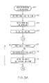
- FIGS. 3A-3B is representative of a software routine executed by signal processor 20 of BUA 16, and shows how the block diagram of FIG. 2 is utilized during reverse operation of the vehicle 10. As indicated at block 60, the flow diagram is entered when the reverse range of vehicle 10 is selected; the routine thereafter remains active so long as the reverse range is engaged.
- AD_THR adaptive adjustment of the target threshold AD_THR occurs except when: (1) a target is detected, or (2) a high clutter condition is recognized. Targets are detected, of course, when the resultant data exceeds AD_THR; and once a target is detected, adaptive adjustment ofAD_THR is suspended until no target is detected for a calibrated time.
- a high clutter condition is recognized by monitoring the rate of change in vehicle speed, since fast changes in vehicle speed result in shifting and flexing of the plastic bumper fascia 14 through which radar signals propagate. Once a high clutter condition is detected, AD_THR is increased to provide high noise rejection, and the low-pass filter 30 is reset after a period of time to re-commence adaptive adjustment of AD_THR.
- blocks 62-66 are executed on entry of the routine, and initialize the adaptive parameters based on the factory-calibrated target discrimination threshold CAL_THR.
- Block 62 determines a noise baseline CAL _NOISE_BASE corresponding to CAL_THR by reducing CAL_THR by a specified amount such as 6 dB.
- Block 64 initializes AD_NOISE_BASE to CAL_NOISE_BASE (as mentioned above in reference to line 42 of the block diagram of FIG. 2 ), and block 66 initializes AD_THR to CAL_THR.
- the main loop of the routine comprising blocks 68-96 is repeatedly executed, as indicated by the circled letters A and B.
- Blocks 68-72 detect and respond to a high clutter condition due to rapid acceleration or deceleration of the vehicle 10.
- Block 68 compares the change in vehicle speed (SPEED_DELTA) to a calibrated reference, such as 10 miles-per-hour-per-second. If SPEED_DELTA exceeds the reference, blocks 70 and 72 are executed to set a delay timer variable (CLUTTER DELAY) to a calibrated number (CAL_DELAY1) and to set AD_THR to the lowest of CAL_THR and (AD_THR + 6 dB).
- CLUTTER DELAY a delay timer variable
- the delay timer variable CLUTTER_DELAY is decremented (by block 90, described below) on each execution of the main loop following detection of the high clutter condition, and effectively measures a time interval such as four (4) seconds.
- Block 72 returns AD_THR to a level that provides high noise rejection if it had been decreased through adaptive adjustment.
- blocks 74 and 76 are then executed to process the received radar data and check for targets.
- the received radar data is processed by range bin to provide a resultant return (resultant data) for each range bin. If the resultant data exceeds AD_THR, a target is detected; otherwise no targets are detected. If block 76 is answered in the affirmative (i.e., target detected), block 78 sets a delay timer variable (LEARN_DELAY) to a calibrated number (CAL DELAY2) to suspend adaptive adjustment of AD_THR, and block 80 executes a driver warning routine that determines if a driver warning should be issued.
- the driver warning routine is not particularly pertinent to the present invention, but typically involves tracking the target detection history and other factors such as the vehicle speed.
- blocks 88-96 process the delay timer variable CLUTTER_DELAY following the detection of a high clutter condition by block 68.
- Blocks 88 and 90 serve to decrement CLUTTER_DELAY if its value is greater than zero. If CLUTTER_DELAY is still greater than zero, block 92 is answered in the negative, and the routine reverts to block 68 as indicated by the circled letter A. However, if decrementing CLUTTER_DELAY reduces its value to zero, block 92 is answered in the affirmative; in this case, block 94 resets the AD_NOISE_BASE of low-pass filter 30, and block 96 updates AD_THR.
- Block 94 Resetting AD_NOISE _BASE at the conclusion of the CLUTTER_DELAY interval (i.e., at block 94) is necessary because block 72 resets AD_THR upon detection of the high clutter condition. Block 94 therefore resets AD_NOISE_BASE to a noise baseline value that corresponds to the reset value of AD_THR.
- the target discrimination threshold AD_THR is initialized to a calibrated value on transition to the reverse range, and is thereafter subject to adaptive adjustment (i.e., learning) for increased target detection sensitivity so long as a target is not detected and the high clutter condition is not detected.
- the adaptive adjustment is carried out by low-pass filtering the resultant data of the radar sensor 18 (starting with the factory-calibrated noise baseline) to determine AD_NOISE_BASE and then calculating AD_THR from AD _NOISE_BASE.
- the adaptive adjustment is suspended when a target is detected, and for a calibrated interval (i.e., the time interval of LEARN_DELAY) after a target is no longer detected.
- AD_THR is immediately increased (if previously lowered by adaptive adjustment), and the low-pass filter 30 is reset to re-commence adaptive adjustment of AD THR when the clutter condition has not been detected for at least a calibrated interval (i.e., the time interval of CLUTTER_DELAY).
- AD_THR is progressively adjusted to the lowest level permitted by the current level of clutter or noise to thereby improve target detection sensitivity without causing false target detection.
- the method of this invention has been described with respect to the illustrated embodiment, it is recognized that numerous modifications and variations in addition to those mentioned herein will occur to those skilled in the art.
- the method may also be applied to forward-looking radars, the low-pass filter 30 may be configured as a second or higher order filter in lieu of the illustrated first-order configuration, and so on. Accordingly, it is intended that the invention not be limited to the disclosed embodiment, but that it have the full scope permitted by the language of the following claims.
Landscapes
- Engineering & Computer Science (AREA)
- Radar, Positioning & Navigation (AREA)
- Remote Sensing (AREA)
- Physics & Mathematics (AREA)
- Computer Networks & Wireless Communication (AREA)
- General Physics & Mathematics (AREA)
- Electromagnetism (AREA)
- Radar Systems Or Details Thereof (AREA)
Abstract
Description
- The present invention relates to a radar-based back-up and parking aid for a motor vehicle, and more particularly to a method of adaptively setting a radar signal threshold for discriminating targets (i.e., objects of interest) from background clutter.
- Motor vehicles can be equipped with a radar-based back-up and parking aid (BUA) such as the Dual-Beam Radar Back-Up Aid produced by Delphi Corporation for producing audible and/or visual driver alerts when an obstacle is detected in the rear travel path of the vehicle. In a typical installation, the system includes a radar sensor module mounted in a protected location behind a plastic fascia that covers the rear bumper. Although the bumper fascia protects the sensor module from physical damage and environmental contamination, it can also increase the effective level of clutter or noise detected by the sensor, particularly under conditions that cause the fascia to shift or flex. Since this and other clutter can be falsely interpreted as an obstacle and result in false target detection, the target discrimination threshold is customarily set to relatively high level for maximum noise rejection. Unfortunately, this can also unnecessarily limit the target detection sensitivity of the system because the same target discrimination threshold is used under all conditions. Accordingly, what is needed is a way of improving the target detection sensitivity without causing false target detection.
- The present invention provides an improved method of operation for a radar-based motor vehicle BUA in which a calibrated target discrimination threshold is adaptively lowered under specified vehicle operating conditions to provide enhanced target detection sensitivity without causing false target detection. The threshold is initialized to a calibrated value on transition to the reverse range, and is thereafter subject to adaptive adjustment for increased target detection sensitivity so long as a target is not detected and a high-clutter condition is not in effect. The adaptive adjustment is carried out by low-pass filtering the resultant data of the radar sensor, starting with a factory-calibrated noise baseline, to determine the current noise level, and then calculating threshold from the determined noise level. The adaptive adjustment is suspended for a calibrated interval after target detection, and the threshold is increased when a high clutter condition is detected based on rate of change in vehicle speed.
-
FIG. 1 is a cross-sectional diagram of a vehicle bumper and radar-based BUA; -
FIG. 2 is a block diagram illustrating an adaptive adjustment of the target discrimination threshold by the BUA ofFIG. 1 according to this invention; and -
FIGS. 3A and3B together depict a flow diagram representative of a method of operation carried out by the BUA ofFIG. 1 according to this invention. - Referring to the drawings, and particularly to
FIG. 1 , thereference numeral 10 generally designates a motor vehicle, including abumper frame 12, a moldedplastic bumper fascia 14, and a radar-basedBUA module 16. In the illustrated embodiment, ahousing 16a ofBUA module 16 is fastened to a vehicle frame element (not shown) abovebumper frame 12. The electronic components of BUA 16, including aradar sensor 18 and a microprocessor-basedsignal processor 20, are mounted on acircuit board 16b, and aradome 16c fastened to thehousing 16a encloses and environmentally seals thecircuit board 16b and theelectronic components radar sensor 18 illuminates a defined area in the rear travel path ofvehicle 10, and quantifies the reflected signal by range bin to form resultant data for comparison with a target discrimination threshold. A target is detected when the resultant data exceeds the threshold, and the presence or absence of targets over a prescribed period of time is analyzed to determine if a driver warning should be issued. - The BUA 16 is initially calibrated for
vehicle 10 at the vehicle factory. For example, the calibration process may involve setting thesignal processor 20 in a calibration mode and placing a standard target in the center of the target detection zone at a predetermined distance fromvehicle 10. After placement of the target, theradar sensor 18 is activated to illuminate the detection zone, and thesignal processor 20 sets the target detection threshold CAL_THR based on the radar return signal. - In subsequent operation of the
BUA 16, the factory-calibrated threshold (CAL_THR) is used to form a target discrimination threshold that is suitable for real-world environments (as compared to the factory-calibration environment). For example, one conventional technique is to multiply CAL_THR by a gain factor that effectively increases CAL_THR by approximately 6 dB. However, setting the target discrimination threshold to such a fixed value tends to unnecessarily reduce the target detection sensitivity under most conditions. - The method of the present invention also utilizes the factory-calibrated target discrimination threshold CAL_THR, but determines the real-world target discrimination threshold (referred to herein as the adaptive threshold, or AD_THR) in a new way that adaptively increases target detection sensitivity without causing false target detection. In general, the
signal processor 20 low-pass filters the resultant data in the absence of a target to determine noise baseline for the resultant data, and then determines AD_THR based on the filter output. Under most conditions, the AD_THR will be significantly lower than CAL_THR, and the target detection sensitivity ofBUA 16 will be correspondingly improved. -
FIG. 2 illustrates the formation of AD_THR as a block diagram in which the resultant data is supplied as an input online 28. A low-pass filter 30 comprising the blocks 32-38 filters the resultant data input, and the filter output (referred to herein as the adaptive noise baseline, or AD_NOISE_BASE) appears online 40.Block 32 determines the sample-to-sample change in the resultant data,block 34 applies a filter time-constant K1 to the determined change, and block 36 sums the output ofblock 34 with the prior value of AD_NOISE _BASE, supplied byblock 38.Broken line 42 signifies that the adaptive noise baseline can be reset to a noise baseline (CAL_NOISE_BASE) corresponding to the factory-calibrated target threshold CAL_THR, as described below in reference toFIGS. 3A-3B . The blocks 44-48 are responsive to the adaptive noise baseline online 40, and produce the adaptive threshold AD_THR online 50.Block 44 represents a threshold multiplier for increasing the adaptive noise baseline by a calibrated amount such as 6 dB, andblock 46 applies a calibrated offset to the output ofblock 44.Block 48 is a minimum value function responsive to both CAL_THR and the output ofblock 46, and ensures that AD_THR will never exceed CAL_THR. - The flow diagram of
FIGS. 3A-3B is representative of a software routine executed bysignal processor 20 of BUA 16, and shows how the block diagram ofFIG. 2 is utilized during reverse operation of thevehicle 10. As indicated at block 60, the flow diagram is entered when the reverse range ofvehicle 10 is selected; the routine thereafter remains active so long as the reverse range is engaged. - In general, adaptive adjustment of the target threshold AD_THR occurs except when: (1) a target is detected, or (2) a high clutter condition is recognized. Targets are detected, of course, when the resultant data exceeds AD_THR; and once a target is detected, adaptive adjustment ofAD_THR is suspended until no target is detected for a calibrated time. A high clutter condition is recognized by monitoring the rate of change in vehicle speed, since fast changes in vehicle speed result in shifting and flexing of the
plastic bumper fascia 14 through which radar signals propagate. Once a high clutter condition is detected, AD_THR is increased to provide high noise rejection, and the low-pass filter 30 is reset after a period of time to re-commence adaptive adjustment of AD_THR. - Referring to
FIG. 3A , blocks 62-66 are executed on entry of the routine, and initialize the adaptive parameters based on the factory-calibrated target discrimination threshold CAL_THR.Block 62 determines a noise baseline CAL _NOISE_BASE corresponding to CAL_THR by reducing CAL_THR by a specified amount such as 6 dB.Block 64 initializes AD_NOISE_BASE to CAL_NOISE_BASE (as mentioned above in reference toline 42 of the block diagram ofFIG. 2 ), andblock 66 initializes AD_THR to CAL_THR. Following initialization, the main loop of the routine comprising blocks 68-96 is repeatedly executed, as indicated by the circled letters A and B. - Blocks 68-72 detect and respond to a high clutter condition due to rapid acceleration or deceleration of the
vehicle 10. Block 68 compares the change in vehicle speed (SPEED_DELTA) to a calibrated reference, such as 10 miles-per-hour-per-second. If SPEED_DELTA exceeds the reference,blocks 70 and 72 are executed to set a delay timer variable (CLUTTER DELAY) to a calibrated number (CAL_DELAY1) and to set AD_THR to the lowest of CAL_THR and (AD_THR + 6 dB). The delay timer variable CLUTTER_DELAY is decremented (byblock 90, described below) on each execution of the main loop following detection of the high clutter condition, and effectively measures a time interval such as four (4) seconds.Block 72 returns AD_THR to a level that provides high noise rejection if it had been decreased through adaptive adjustment. - Referring to
FIG. 3B ,blocks block 76 is answered in the affirmative (i.e., target detected),block 78 sets a delay timer variable (LEARN_DELAY) to a calibrated number (CAL DELAY2) to suspend adaptive adjustment of AD_THR, andblock 80 executes a driver warning routine that determines if a driver warning should be issued. The driver warning routine is not particularly pertinent to the present invention, but typically involves tracking the target detection history and other factors such as the vehicle speed. Once a target is no longer detected, block 76 is answered in the negative, and block 82 checks the delay timer variable LEARN_DELAY to determine if adaptive adjustment of AD_THR is being delayed due to target detection. If LEARN_DELAY is greater than zero, adaptive adjustment of AD_THR is not permitted; in this case, block 84 decrements LEARN_DELAY and block 80 executes the driver warning routine. Ifblock 82 is answered in the negative (i.e., LEARN_DELAY <= 0), adaptive adjustment of AD_THR is permitted, and block 86 is executed to adaptively update AD_THR before executing the driver warning routine ofblock 80. Adaptive updating of AD_THR occurs as described above in reference to the block diagram ofFIG. 2 . - Finally, blocks 88-96 process the delay timer variable CLUTTER_DELAY following the detection of a high clutter condition by block 68.
Blocks pass filter 30, and block 96 updates AD_THR. Resetting AD_NOISE _BASE at the conclusion of the CLUTTER_DELAY interval (i.e., at block 94) is necessary becauseblock 72 resets AD_THR upon detection of the high clutter condition.Block 94 therefore resets AD_NOISE_BASE to a noise baseline value that corresponds to the reset value of AD_THR. - In summary, the target discrimination threshold AD_THR is initialized to a calibrated value on transition to the reverse range, and is thereafter subject to adaptive adjustment (i.e., learning) for increased target detection sensitivity so long as a target is not detected and the high clutter condition is not detected. The adaptive adjustment is carried out by low-pass filtering the resultant data of the radar sensor 18 (starting with the factory-calibrated noise baseline) to determine AD_NOISE_BASE and then calculating AD_THR from AD _NOISE_BASE. The adaptive adjustment is suspended when a target is detected, and for a calibrated interval (i.e., the time interval of LEARN_DELAY) after a target is no longer detected. And when a high clutter condition is detected, AD_THR is immediately increased (if previously lowered by adaptive adjustment), and the low-
pass filter 30 is reset to re-commence adaptive adjustment of AD THR when the clutter condition has not been detected for at least a calibrated interval (i.e., the time interval of CLUTTER_DELAY). In this way, AD_THR is progressively adjusted to the lowest level permitted by the current level of clutter or noise to thereby improve target detection sensitivity without causing false target detection. - While the method of this invention has been described with respect to the illustrated embodiment, it is recognized that numerous modifications and variations in addition to those mentioned herein will occur to those skilled in the art. For example, the method may also be applied to forward-looking radars, the low-
pass filter 30 may be configured as a second or higher order filter in lieu of the illustrated first-order configuration, and so on. Accordingly, it is intended that the invention not be limited to the disclosed embodiment, but that it have the full scope permitted by the language of the following claims.
Claims (8)
- A method of adaptively improving a target detection sensitivity of a motor vehicle radar (16) that detects a target when a resultant signal of said radar exceeds a target discrimination threshold, comprising the steps of:initially setting said target discrimination threshold to a calibrated threshold (66);determining an initial noise baseline corresponding to said calibrated threshold (62);low-pass filtering said resultant radar signal, starting with said initial noise baseline, when no target is detected to form an adaptive noise baseline (30); andperiodically adjusting said target discrimination threshold to a new value based on said adaptive noise baseline (86).
- The method of claim 1, including the step of:suspending said low-pass filtering when said resultant signal exceeds said target discrimination threshold (76).
- The method of claim 2, including the step of:re-commencing said low-pass filtering when no target is detected for at least a predetermined time (76, 78, 82, 86, 30).
- The method of claim 1, including the steps of:detecting a condition associated with a high level of background clutter (68); andincreasing the value of said target discrimination threshold upon detection of said condition (72).
- The method of claim 4, including the step of:limiting the increasing of said target discrimination threshold as required to prevent said target discrimination threshold from exceeding said calibrated threshold (72).
- The method of claim 4, where said condition is detected when a rate of change in vehicle speed exceeds a calibrated rate of change (68).
- The method of claim 4, including the step of:suspending said low-pass filtering upon detection of said condition (70, 88).
- The method of claim 7, including the steps of:determining an new noise baseline corresponding to the increased value of said target discrimination threshold (94); andre-commencing said low-pass filtering said resultant radar signal, starting with said new noise baseline, when said condition has not been detected for at least a predetermined time (72, 92, 96).
Applications Claiming Priority (1)
| Application Number | Priority Date | Filing Date | Title |
|---|---|---|---|
| US11/706,017 US7477181B2 (en) | 2007-02-14 | 2007-02-14 | Method of adaptively adjusting the target detection sensitivity of a motor vehicle radar |
Publications (1)
| Publication Number | Publication Date |
|---|---|
| EP1959269A1 true EP1959269A1 (en) | 2008-08-20 |
Family
ID=39469603
Family Applications (1)
| Application Number | Title | Priority Date | Filing Date |
|---|---|---|---|
| EP08151013A Ceased EP1959269A1 (en) | 2007-02-14 | 2008-02-04 | Method of adaptively adjusting the target detection sensitivity of a motor vehicle radar |
Country Status (2)
| Country | Link |
|---|---|
| US (1) | US7477181B2 (en) |
| EP (1) | EP1959269A1 (en) |
Cited By (1)
| Publication number | Priority date | Publication date | Assignee | Title |
|---|---|---|---|---|
| CN111323757A (en) * | 2019-12-30 | 2020-06-23 | 北京海兰信数据科技股份有限公司 | Target detection method and device for marine radar |
Families Citing this family (13)
| Publication number | Priority date | Publication date | Assignee | Title |
|---|---|---|---|---|
| US7477181B2 (en) * | 2007-02-14 | 2009-01-13 | Delphi Technologies, Inc. | Method of adaptively adjusting the target detection sensitivity of a motor vehicle radar |
| US20120085774A1 (en) * | 2010-10-07 | 2012-04-12 | Ropak Corporation | One-piece container handle |
| DE102014225830A1 (en) * | 2014-12-15 | 2016-06-16 | Robert Bosch Gmbh | Method for calibrating a radar system |
| CN104931939B (en) * | 2015-06-03 | 2017-03-15 | 河海大学 | A kind of missile-borne repeating jamming suppressing method based on decoy feature |
| US9828036B2 (en) | 2015-11-24 | 2017-11-28 | Srg Global Inc. | Active grille shutter system with integrated radar |
| US9925867B2 (en) * | 2016-01-11 | 2018-03-27 | Ford Global Technologies, Llc | Fuel control regulator system with acoustic pliability |
| WO2019119195A1 (en) * | 2017-12-18 | 2019-06-27 | 深圳市大疆创新科技有限公司 | Target signal detection method and device, unmanned aerial vehicle, and agricultural unmanned aerial vehicle |
| WO2020133223A1 (en) * | 2018-12-28 | 2020-07-02 | 深圳市大疆创新科技有限公司 | Target detection method, radar, vehicle and computer-readable storage medium |
| CN109977570B (en) * | 2019-04-01 | 2023-06-30 | 奇瑞汽车股份有限公司 | Method, device and storage medium for determining vehicle body noise |
| CN110082754B (en) * | 2019-04-19 | 2021-09-17 | 北京海兰信数据科技股份有限公司 | Weak target self-adaptive detection system and detection method based on tracking feedback |
| US11378652B2 (en) * | 2019-09-03 | 2022-07-05 | GM Global Technology Operations LLC | Enhancement of vehicle radar system robustness based on elevation information |
| TWI734252B (en) * | 2019-11-08 | 2021-07-21 | 立積電子股份有限公司 | Radar and method of updating background components of echo signal for radar |
| CN113625240B (en) * | 2020-05-06 | 2022-05-24 | 华为技术有限公司 | Signal detection method and device and radar system |
Citations (5)
| Publication number | Priority date | Publication date | Assignee | Title |
|---|---|---|---|---|
| US3171119A (en) | 1961-10-11 | 1965-02-23 | Nuese Carlos | Binomial sequential detector |
| US5225839A (en) * | 1980-12-29 | 1993-07-06 | Okurowski Frank A | All weather tactical strike system (AWTSS) and method of operation |
| WO2002054099A2 (en) | 2000-12-29 | 2002-07-11 | Honeywell International Inc. | Calibration method for a radar object detection system |
| WO2003046605A1 (en) | 2001-10-12 | 2003-06-05 | Hi-Key Limited | A method and apparatus for analysing a signal from a movement detector for determining if movement has been detected in an area under surveillance, and an anti-theft system |
| EP1562050A1 (en) | 2004-02-06 | 2005-08-10 | Robert Bosch GmbH | Method and apparatus for adapting a threshold in a detection unit |
Family Cites Families (12)
| Publication number | Priority date | Publication date | Assignee | Title |
|---|---|---|---|---|
| GB8422022D0 (en) * | 1984-08-31 | 1984-10-24 | Atomic Energy Authority Uk | Electrical signal discrimination |
| US6229475B1 (en) * | 1987-04-27 | 2001-05-08 | Raytheon Company | Pulse doppler radar system with improved cluster target resolution capability |
| US5150334A (en) * | 1991-09-16 | 1992-09-22 | Bindicator Company | System and method for ultrasonic measurement of material level |
| US5357256A (en) * | 1993-08-17 | 1994-10-18 | Alliedsignal Inc. | Radar receiver with adaptive clutter threshold reference |
| GB9718321D0 (en) * | 1997-09-01 | 1997-11-05 | Cambridge Consultants | Electromagnetic sensor system |
| DE10100596A1 (en) * | 2001-01-09 | 2002-07-11 | Bosch Gmbh Robert | Method for processing output or basic signals of a device for determining a distance of an object |
| AUPR301401A0 (en) * | 2001-02-09 | 2001-03-08 | Commonwealth Scientific And Industrial Research Organisation | Lidar system and method |
| US6456231B1 (en) * | 2001-06-01 | 2002-09-24 | Mcewan Technologies, Llc | Radar sensor having a CFAR detector |
| US6433730B1 (en) * | 2001-06-07 | 2002-08-13 | The United States Of America As Represented By The Secretary Of The Navy | Noise riding threshold control with immunity to signals with high pulse repetition frequencies and high duty cycles |
| US6583754B2 (en) * | 2001-10-31 | 2003-06-24 | Deere & Company | Fast fourier transform signal processing method for doppler radar speed sensor |
| BR0308287A (en) * | 2002-03-13 | 2005-01-11 | Raytheon Canada Ltd | Adaptive detection system and method |
| US7477181B2 (en) * | 2007-02-14 | 2009-01-13 | Delphi Technologies, Inc. | Method of adaptively adjusting the target detection sensitivity of a motor vehicle radar |
-
2007
- 2007-02-14 US US11/706,017 patent/US7477181B2/en active Active
-
2008
- 2008-02-04 EP EP08151013A patent/EP1959269A1/en not_active Ceased
Patent Citations (5)
| Publication number | Priority date | Publication date | Assignee | Title |
|---|---|---|---|---|
| US3171119A (en) | 1961-10-11 | 1965-02-23 | Nuese Carlos | Binomial sequential detector |
| US5225839A (en) * | 1980-12-29 | 1993-07-06 | Okurowski Frank A | All weather tactical strike system (AWTSS) and method of operation |
| WO2002054099A2 (en) | 2000-12-29 | 2002-07-11 | Honeywell International Inc. | Calibration method for a radar object detection system |
| WO2003046605A1 (en) | 2001-10-12 | 2003-06-05 | Hi-Key Limited | A method and apparatus for analysing a signal from a movement detector for determining if movement has been detected in an area under surveillance, and an anti-theft system |
| EP1562050A1 (en) | 2004-02-06 | 2005-08-10 | Robert Bosch GmbH | Method and apparatus for adapting a threshold in a detection unit |
Cited By (2)
| Publication number | Priority date | Publication date | Assignee | Title |
|---|---|---|---|---|
| CN111323757A (en) * | 2019-12-30 | 2020-06-23 | 北京海兰信数据科技股份有限公司 | Target detection method and device for marine radar |
| CN111323757B (en) * | 2019-12-30 | 2022-04-05 | 北京海兰信数据科技股份有限公司 | Target detection method and device for marine radar |
Also Published As
| Publication number | Publication date |
|---|---|
| US7477181B2 (en) | 2009-01-13 |
| US20080191930A1 (en) | 2008-08-14 |
Similar Documents
| Publication | Publication Date | Title |
|---|---|---|
| US7477181B2 (en) | Method of adaptively adjusting the target detection sensitivity of a motor vehicle radar | |
| US11131766B2 (en) | Method for the recognition of an object | |
| US6515615B2 (en) | Signal processing method | |
| US10656245B2 (en) | Automotive radar sensor blockage detection using adaptive overlapping visibility | |
| CN107521409B (en) | Blind spot detection system and method | |
| EP1378764B1 (en) | Object detection system and method of estimating object size | |
| EP3617740B1 (en) | Target detection in rainfall and snowfall conditions using mmwave radar | |
| EP3291205A1 (en) | Camera based trailer identification and blind zone adjustment | |
| KR20170096598A (en) | Radar employing preacquisition ramps | |
| US9977126B2 (en) | Radar apparatus | |
| US12228672B2 (en) | Device and method for detecting blockage of radar sensor, and radar apparatus | |
| JP2002202360A (en) | Vertical axial deviation detector of onboard radar | |
| EP2506033A2 (en) | Monitoring apparatus and method | |
| CN113960538A (en) | Radar signal processing method, device and storage medium | |
| US20190041497A1 (en) | Controller using map attributes to qualify radar returns | |
| CN116263493A (en) | Radar anti-spoofing system for autonomous vehicles to identify ghost vehicles | |
| US7532152B1 (en) | Automotive radar system | |
| EP3693760A1 (en) | Trailer detection system and method | |
| CN112444780B (en) | Enhancement of vehicle radar system robustness based on altitude information | |
| US11346939B2 (en) | Surrounding monitoring radar device | |
| JP3397732B2 (en) | FM-CW radar device | |
| JP2019158787A (en) | Radar device and signal processing method | |
| KR20210136542A (en) | Radar System for Vehicle And Control Method Therefor | |
| EP3454076A1 (en) | Mimo detector device useful for automated vehicles | |
| JPH11344559A (en) | FM-CW radar signal processing device |
Legal Events
| Date | Code | Title | Description |
|---|---|---|---|
| PUAI | Public reference made under article 153(3) epc to a published international application that has entered the european phase |
Free format text: ORIGINAL CODE: 0009012 |
|
| AK | Designated contracting states |
Kind code of ref document: A1 Designated state(s): AT BE BG CH CY CZ DE DK EE ES FI FR GB GR HR HU IE IS IT LI LT LU LV MC MT NL NO PL PT RO SE SI SK TR |
|
| AX | Request for extension of the european patent |
Extension state: AL BA MK RS |
|
| 17P | Request for examination filed |
Effective date: 20090220 |
|
| 17Q | First examination report despatched |
Effective date: 20090320 |
|
| AKX | Designation fees paid |
Designated state(s): AT BE BG CH CY CZ DE DK EE ES FI FR GB GR HR HU IE IS IT LI LT LU LV MC MT NL NO PL PT RO SE SI SK TR |
|
| STAA | Information on the status of an ep patent application or granted ep patent |
Free format text: STATUS: THE APPLICATION HAS BEEN REFUSED |
|
| 18R | Application refused |
Effective date: 20161216 |