EP1959232A1 - Angular speed sensor - Google Patents
Angular speed sensor Download PDFInfo
- Publication number
- EP1959232A1 EP1959232A1 EP06843048A EP06843048A EP1959232A1 EP 1959232 A1 EP1959232 A1 EP 1959232A1 EP 06843048 A EP06843048 A EP 06843048A EP 06843048 A EP06843048 A EP 06843048A EP 1959232 A1 EP1959232 A1 EP 1959232A1
- Authority
- EP
- European Patent Office
- Prior art keywords
- signal
- vibrator
- angular velocity
- difference
- detection signal
- Prior art date
- Legal status (The legal status is an assumption and is not a legal conclusion. Google has not performed a legal analysis and makes no representation as to the accuracy of the status listed.)
- Withdrawn
Links
Images




Classifications
-
- G—PHYSICS
- G01—MEASURING; TESTING
- G01C—MEASURING DISTANCES, LEVELS OR BEARINGS; SURVEYING; NAVIGATION; GYROSCOPIC INSTRUMENTS; PHOTOGRAMMETRY OR VIDEOGRAMMETRY
- G01C19/00—Gyroscopes; Turn-sensitive devices using vibrating masses; Turn-sensitive devices without moving masses; Measuring angular rate using gyroscopic effects
- G01C19/56—Turn-sensitive devices using vibrating masses, e.g. vibratory angular rate sensors based on Coriolis forces
- G01C19/5607—Turn-sensitive devices using vibrating masses, e.g. vibratory angular rate sensors based on Coriolis forces using vibrating tuning forks
- G01C19/5614—Signal processing
-
- G—PHYSICS
- G01—MEASURING; TESTING
- G01C—MEASURING DISTANCES, LEVELS OR BEARINGS; SURVEYING; NAVIGATION; GYROSCOPIC INSTRUMENTS; PHOTOGRAMMETRY OR VIDEOGRAMMETRY
- G01C19/00—Gyroscopes; Turn-sensitive devices using vibrating masses; Turn-sensitive devices without moving masses; Measuring angular rate using gyroscopic effects
- G01C19/56—Turn-sensitive devices using vibrating masses, e.g. vibratory angular rate sensors based on Coriolis forces
-
- G—PHYSICS
- G01—MEASURING; TESTING
- G01C—MEASURING DISTANCES, LEVELS OR BEARINGS; SURVEYING; NAVIGATION; GYROSCOPIC INSTRUMENTS; PHOTOGRAMMETRY OR VIDEOGRAMMETRY
- G01C19/00—Gyroscopes; Turn-sensitive devices using vibrating masses; Turn-sensitive devices without moving masses; Measuring angular rate using gyroscopic effects
- G01C19/56—Turn-sensitive devices using vibrating masses, e.g. vibratory angular rate sensors based on Coriolis forces
- G01C19/5607—Turn-sensitive devices using vibrating masses, e.g. vibratory angular rate sensors based on Coriolis forces using vibrating tuning forks
-
- H—ELECTRICITY
- H10—SEMICONDUCTOR DEVICES; ELECTRIC SOLID-STATE DEVICES NOT OTHERWISE PROVIDED FOR
- H10N—ELECTRIC SOLID-STATE DEVICES NOT OTHERWISE PROVIDED FOR
- H10N30/00—Piezoelectric or electrostrictive devices
Definitions
- the present invention relates to an angular velocity sensor.
- Fig. 5 is a block diagram of a conventional angular velocity sensor 5001 disclosed in Patent Document 1.
- Figs. 6 and 7 illustrate the waveforms of signals in the angular velocity sensor 5001.
- the angular velocity sensor 5001 includes a vibrator 2, a driver circuit 4 for driving the vibrator 2, and a detector 6 for detecting distortions produced in the vibrator 2.
- the vibrator 2 has any of various shapes, such as a tuning-fork shape, an H-shape, a T-shape, and a reed shape.
- a Coriolis force an inertial force
- the Coriolis force provides the vibrator 2 with a distortion.
- the distortion is electrically detected to calculate the angular velocity of the vibrator 2.
- the vibrator 2 includes a vibrator element 2A mechanically vibrating, and a driver 8, a monitor 14, and sensors 10 and 12 which are provided at the vibrator element 2A.
- the driver 8 causes the vibrator 2 (the vibrator element 2A) to vibrate upon receiving a driving signal from the driver circuit 4.
- the sensors 10 and 12 outputs the distortion produced in the vibrator element 2A due to the Coriolis force resulting from the rotation of the vibrator element 2A as detection signals 501H and 501J, respectively.
- the monitor 14 detects the status of the vibration of the vibrator element 2A, and output the status as a monitor signal 501A.
- the detector 6 shapes the monitor signal 501A into a square waveform and outputs a shaped signal 501B.
- the detection signals 501H and 501J generally contain distortion components representing the distortion produced in the vibrator 2 due to the Coriolis force and noise components.
- the noise components are removed from the detection signals 501H and 501J while only the distortion components are taken and used to calculate the angular velocity.
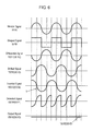
- Fig. 6 illustrates the waveforms of the signals 501A and 501B and signals 1501C to 1501G which are carried in the noise components of the angular sensor 5001.
- Fig. 7 illustrates the waveforms of the signals 501A and 501B and signals 2501C to 2501G which are carried in the distortion components of the angular sensor 5001.
- the sums of the signals 1501C to 1501G and the signals 2501C to 2501G are denoted by signals 501C to 501G, respectively.
- the detection signals 501H and 501J output from the sensors 10 and 12 are input to a differential amplifier 18.
- the differential amplifier 18 outputs a difference signal 501C, the difference between the signals 501H and 501J.
- a phase shifter 20 provides a shifted signal 501D by causing the difference signal 501C to shift (delay) in phase by 90 degrees.
- An inverter amplifier 22 inverts the shifted signal 501D to provide an inverted signal 501E.
- a synchronous detector 24 synchronously detects the shifted signal 501D and the inverted signal 501E with reference to the shaped signal 501B as to output a detected signal 501F.
- a processor 26 smoothes the detected signal 501F to provide an output signal 501G.
- the angular velocity of the vibrator 2 is calculated from the output signal 501G.
- the inverted signal 501E (the sum of the signals 1501E and 2501E) delays in phase from the shifted signal 501D (the signals 1501D and 2501D) due to the inversion amplifier 22. More specifically, the inverted signal 501E (the signals 1501E and 2501E) is not completely inverted form the shifted signal 501D (the signals 1501D and 2501D), and delays by a period T of time from the shifted signal 501D (the signals 1501D and 2501D).
- the detected signal 501F (the signals 1501F and 2501F) is smoothes to provide the output signal 501G (the signals 1501G and 2501G).
- the output signal 501G contains the signal 1501E (the signal 501E), an error caused by the period T, hence preventing the angular velocity of the vibrator 2 from being detected accurately.
- Patent Document 1 Japanese Patent Laid-Open Publication No. 2002-243451 .
- An angular velocity sensor includes a vibrator vibrating, first and second differential circuits for outputting first and second difference signals, respectively, and a synchronous detector circuit for synchronously detecting the first and second difference signals.
- First and second sensors outputs first and second detection signals in response to a distortion produced due to an inertial force.
- the second detection signal has a phase reverse to a phase of the first detection signal.
- the first difference signal corresponds to a difference provided by subtracting the first detection signal from the second detection signal.
- the second difference signal corresponds to a difference provided by subtracting the second detection signal from the first detection signal.
- This angular velocity sensor detects an angular velocity of the vibrator accurately.
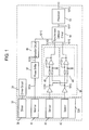
- Fig. 1 is a block diagram of an angular velocity sensor 1001 according to an exemplary embodiment of the present invention.
- Figs. 2A and 2B are a plan view and a cross sectional view of a vibrator 32 of the angular velocity sensor 1001, respectively.
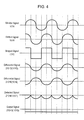
- Figs. 3 and 4 illustrate the waveforms of signals of the angular velocity sensor 1001.
- the angular velocity sensor 1001 includes the vibrator 32, a driver circuit 34 for vibrating the vibrator 32, and a detector circuit 36 for detecting a distortion produced in the vibrator 32.
- the vibrator 32 has any of various shapes, such as a tuning-fork shape, an H-shape, a T-shape, and a reed shape.
- a Coriolis force, an inertial force, produced by the vibration and rotation provides the vibrator 32 with a distortion.
- the angular velocity sensor 101 detects the distortion electrically to calculate the angular velocity of the vibrator 32.
- the vibrator 32 includes a vibrator element 32A mechanically vibrating, a driver 38, sensors 40 and 42, and a monitor 44.
- the driver 38 causes the vibrator element 32A to vibrate in response to a driving signal supplied from the driver circuit 34.
- the sensors 40 and 42 outputs, to the detector circuit 36, detection signals 101H and 101J representing the distortion produced by the Coriolis force.
- the monitor 44 outputs a monitor signal 101A corresponding to the vibration of the vibrator element 32A.
- the vibrator element 32A made of a silicon substrate includes a base 41 and arms 43A and 43B joined to the base 41, thus having a tuning fork shape.
- each of the driving electrodes 45 and the sensing electrodes 47 includes a conductive layer 201 made of metal, such as Ag or Au, provided on the vibrator element 32A, a piezoelectric layer 202 made of lead zirconium titanate (PZT) provided on the conductive layer 201, and a conductive layer 203 made of metal, such as Ag or Au, provided on the piezoelectric layer 202.
- the monitor 38 also includes electrodes identical to those of the driver 38 and the sensors 40 and 42.
- the driver 38 is provided on the arms 43A and 43B for vibrating the vibrator 32 along a direction 32B which the arms 43A and 43B moves in or and which the arms 43A and 43B are aligned in.
- the driver circuit 34 includes an amplifier having an automatic gain control function for controlling a driving voltage supplied to the driver 38 (between the electrodes 45) in order to vibrate the vibrator 32 (the vibrator element 32A) at a constant amplitude.
- the detector circuit 36 includes a differential circuit and an integral circuit for processing detection signals 101H and 101J output from the sensing electrodes 47 due to the distortion produced in the vibrator 32 by a Coriolis force.
- the monitor 44 monitors the vibration of the vibrator 32 (the vibrator element 32A) and outputs a monitor signal 101A in response to the displacements of the arms 43A, 43B of the vibrator 32.
- a phase shifter 50 causes the monitor signal 101A to shift (delay) in phase by 90 degrees shift (or delayed) to output a shifted signal 101B.
- a detector 46 detects the shifted signal 101B to shape the signal 101B into a square waveform which has two, high and low, levels and outputs it as a shaped signal 101C.
- the sensors 40 and 42 are mounted on the arms 43A and 43B, respectively. Detection signals 101H and 101J output from the sensors 40 and 42 has phases reverse to each other, thus being inverted to each other.
- the detection signals 101H and 101J being inverted to each other are input to differential circuits 48 and 49, respectively.
- the differential circuit 48 outputs a differential signal 101D, the difference provided by subtracting the detection signal 101H from the detection signal 101J.
- the differential circuit 49 outputs a differential signal 101E, the difference provided by subtracting the detection signal 101J from the detection signal 101H. This structure prevents the difference signals 101D and 101E from having different phases, thus allowing the signals 101D and 101E to have waveforms reversed completely to each other.
- the difference signals 101D and 101E are synchronously detected with reference to the shaped signal 101C by a synchronous detector circuit 54 to provide a detected signal 101F.
- the synchronous detector circuit 54 when the shaped signal 101C is at the high level, the synchronous detector circuit 54 outputs the difference signal 101D as the detected signal 101F.
- the detector circuit 54 In the shaped signal 101C is at the low level, the detector circuit 54 inverts the differential signal 101E and outputs it as the detected signal 101F.
- the detected signal 101F is then smoothed by a processor 56 to provide an output signal 101G.
- the angular velocity of the vibrator 32 is calculated from the output signal 101G.
- the detection signals 101H and 101J contain distortion components representing the distortion produced in the vibrator 32 due to the Coriolis force, and noise components. As the noise components have been removed from the detection signals 101H and 101J, the angular velocity is calculated based on only the distortion components.
- Fig. 3 illustrates the waveforms of the signals 101A to 101C and signals 1101D to 1101G which are carried in the noise components of the angular sensor 1001.
- Fig. 4 illustrates the waveforms of the signals 101A to 101C and signals 2101D to 2101G which are carried in the distortion components of the angular sensor 1001.
- Signals 101D to 101G are the sums of the signals 1101D to 1101G and the signals 2101D to 2101G, respectively.
- the detection signals 101H and 101J has phase reversed to each other.
- the difference signal 101D is provided by subtracting the detection signal 101H from the detection signal 101J while the difference signal 101E is provided by subtracting the detection signal 101J from the detection signal 101H. This prevents the difference signals 101D and 101E from having different phases, thus allowing the signals 101D and 101E to be reversed to each other.
- the difference signals 101D and 101E are synchronously detected with reference to the shaped signal 101C, and thereby, prevent the output signal 101G from containing an error caused by the phase difference, hence the angular velocity of the vibrator 32 to be calculated accurately based on the output signal 101G.
- An angular velocity sensor detects an angular velocity of the vibrator accurately, and is useful for various electronic devices detecting angular velocities.
Landscapes
- Engineering & Computer Science (AREA)
- Physics & Mathematics (AREA)
- General Physics & Mathematics (AREA)
- Radar, Positioning & Navigation (AREA)
- Remote Sensing (AREA)
- Signal Processing (AREA)
- Gyroscopes (AREA)
Abstract
An angular velocity sensor includes a vibrator vibrating, first and second differential circuits for outputting first and second difference signals, respectively, and a synchronous detector circuit for synchronously detecting the first and second difference signals. First and second sensors outputs first and second detection signals in response to a distortion produced due to an inertial force. The second detection signal has a phase reverse to a phase of the first detection signal. The first difference signal corresponds to a difference provided by subtracting the first detection signal from the second detection signal. The second difference signal corresponds to a difference provided by subtracting the second detection signal from the first detection signal. This angular velocity sensor detects an angular velocity of the vibrator accurately.
Description
- The present invention relates to an angular velocity sensor.
-
Fig. 5 is a block diagram of a conventionalangular velocity sensor 5001 disclosed inPatent Document 1.Figs. 6 and7 illustrate the waveforms of signals in theangular velocity sensor 5001. Theangular velocity sensor 5001 includes avibrator 2, a driver circuit 4 for driving thevibrator 2, and adetector 6 for detecting distortions produced in thevibrator 2. Thevibrator 2 has any of various shapes, such as a tuning-fork shape, an H-shape, a T-shape, and a reed shape. Upon vibrating and rotating, a Coriolis force (an inertial force) is generated. The Coriolis force provides thevibrator 2 with a distortion. The distortion is electrically detected to calculate the angular velocity of thevibrator 2. - The
vibrator 2 includes avibrator element 2A mechanically vibrating, and adriver 8, a monitor 14, and sensors 10 and 12 which are provided at thevibrator element 2A. Thedriver 8 causes the vibrator 2 (thevibrator element 2A) to vibrate upon receiving a driving signal from the driver circuit 4. The sensors 10 and 12 outputs the distortion produced in thevibrator element 2A due to the Coriolis force resulting from the rotation of thevibrator element 2A asdetection signals vibrator element 2A, and output the status as amonitor signal 501A. Thedetector 6 shapes themonitor signal 501A into a square waveform and outputs ashaped signal 501B. - The
detection signals vibrator 2 due to the Coriolis force and noise components. In theangular velocity sensor 5001, the noise components are removed from thedetection signals -
Fig. 6 illustrates the waveforms of thesignals signals 1501C to 1501G which are carried in the noise components of theangular sensor 5001.Fig. 7 illustrates the waveforms of thesignals signals 2501C to 2501G which are carried in the distortion components of theangular sensor 5001. The sums of thesignals 1501C to 1501G and thesignals 2501C to 2501G are denoted bysignals 501C to 501G, respectively. - The
detection signals differential amplifier 18. Thedifferential amplifier 18 outputs adifference signal 501C, the difference between thesignals phase shifter 20 provides a shiftedsignal 501D by causing thedifference signal 501C to shift (delay) in phase by 90 degrees. Aninverter amplifier 22 inverts the shiftedsignal 501D to provide an invertedsignal 501E. - A
synchronous detector 24 synchronously detects the shiftedsignal 501D and the invertedsignal 501E with reference to theshaped signal 501B as to output a detectedsignal 501F. Aprocessor 26 smoothes the detectedsignal 501F to provide anoutput signal 501G. The angular velocity of thevibrator 2 is calculated from theoutput signal 501G. - The inverted
signal 501E (the sum of thesignals signal 501D (thesignals inversion amplifier 22. More specifically, the invertedsignal 501E (thesignals signal 501D (thesignals signal 501D (thesignals signal 501F (thesignals output signal 501G (thesignals output signal 501G contains thesignal 1501E (thesignal 501E), an error caused by the period T, hence preventing the angular velocity of thevibrator 2 from being detected accurately. - Patent Document 1: Japanese Patent Laid-Open Publication No.
2002-243451 - An angular velocity sensor includes a vibrator vibrating, first and second differential circuits for outputting first and second difference signals, respectively, and a synchronous detector circuit for synchronously detecting the first and second difference signals. First and second sensors outputs first and second detection signals in response to a distortion produced due to an inertial force. The second detection signal has a phase reverse to a phase of the first detection signal. The first difference signal corresponds to a difference provided by subtracting the first detection signal from the second detection signal. The second difference signal corresponds to a difference provided by subtracting the second detection signal from the first detection signal.
- This angular velocity sensor detects an angular velocity of the vibrator accurately.
-
-
Fig. 1 is a block diagram of an angular velocity sensor according to an exemplary embodiment of the present invention. -
Fig. 2A is a plan view of a vibrator of the angular velocity sensor according to the embodiment. -
Fig. 2B is a cross sectional view of the vibrator of the angular velocity sensor according to the embodiment. -
Fig. 3 illustrates the waveforms of signals of the angular velocity sensor according to the embodiment. -
Fig. 4 illustrates the waveforms of signals of the angular velocity sensor according to the embodiment. -
Fig. 5 is a block diagram of a conventional angular velocity sensor. -
Fig. 6 illustrates the waveforms of signals of the conventional angular velocity sensor. -
Fig. 7 illustrates the waveforms of signals of the conventional angular velocity sensor. -
- 32
- Vibrator
- 32A
- Vibrator Element
- 40
- Sensor (First Sensor)
- 41
- Base
- 42
- Sensor (Second Sensor)
- 43A
- Arm (First Arm)
- 43B
- Arm (Second (Arm)
- 44
- Monitor
- 48
- Differential Circuit (First Differential Circuit)
- 49
- Differential Circuit (Second Differential Circuit)
- 50
- Phase Shifter
- 54
- Synchronous Detector Circuit
- 101D
- Differential Signal
- 101E
- Differential Signal
- 101H
- Detection Signal
- 101J
- Detection Signal
-
Fig. 1 is a block diagram of an angular velocity sensor 1001 according to an exemplary embodiment of the present invention.Figs. 2A and 2B are a plan view and a cross sectional view of avibrator 32 of the angular velocity sensor 1001, respectively.Figs. 3 and4 illustrate the waveforms of signals of the angular velocity sensor 1001. - The angular velocity sensor 1001 includes the
vibrator 32, adriver circuit 34 for vibrating thevibrator 32, and adetector circuit 36 for detecting a distortion produced in thevibrator 32. Thevibrator 32 has any of various shapes, such as a tuning-fork shape, an H-shape, a T-shape, and a reed shape. When thevibrator 32 rotates while vibrating, a Coriolis force, an inertial force, produced by the vibration and rotation provides thevibrator 32 with a distortion. The angular velocity sensor 101 detects the distortion electrically to calculate the angular velocity of thevibrator 32. - The
vibrator 32 includes avibrator element 32A mechanically vibrating, adriver 38,sensors monitor 44. Thedriver 38 causes thevibrator element 32A to vibrate in response to a driving signal supplied from thedriver circuit 34. Thesensors detector circuit 36,detection signals monitor 44 outputs amonitor signal 101A corresponding to the vibration of thevibrator element 32A. As shown inFig. 2A , thevibrator element 32A made of a silicon substrate includes abase 41 andarms base 41, thus having a tuning fork shape. Drivingelectrodes 45 andsensing electrodes 47 functioning as thedriver 38 and thesensors vibrator element 32A. As shown inFig. 2B , each of the drivingelectrodes 45 and thesensing electrodes 47 includes aconductive layer 201 made of metal, such as Ag or Au, provided on thevibrator element 32A, apiezoelectric layer 202 made of lead zirconium titanate (PZT) provided on theconductive layer 201, and aconductive layer 203 made of metal, such as Ag or Au, provided on thepiezoelectric layer 202. Themonitor 38 also includes electrodes identical to those of thedriver 38 and thesensors driver 38 is provided on thearms vibrator 32 along a direction 32B which thearms arms - The
driver circuit 34 includes an amplifier having an automatic gain control function for controlling a driving voltage supplied to the driver 38 (between the electrodes 45) in order to vibrate the vibrator 32 (thevibrator element 32A) at a constant amplitude. Thedetector circuit 36 includes a differential circuit and an integral circuit for processingdetection signals sensing electrodes 47 due to the distortion produced in thevibrator 32 by a Coriolis force. - The
monitor 44 monitors the vibration of the vibrator 32 (thevibrator element 32A) and outputs amonitor signal 101A in response to the displacements of thearms vibrator 32. Aphase shifter 50 causes themonitor signal 101A to shift (delay) in phase by 90 degrees shift (or delayed) to output a shiftedsignal 101B. Adetector 46 detects the shiftedsignal 101B to shape thesignal 101B into a square waveform which has two, high and low, levels and outputs it as ashaped signal 101C. - The
sensors arms sensors differential circuits differential circuit 48 outputs adifferential signal 101D, the difference provided by subtracting thedetection signal 101H from thedetection signal 101J. Thedifferential circuit 49 outputs adifferential signal 101E, the difference provided by subtracting thedetection signal 101J from thedetection signal 101H. This structure prevents the difference signals 101D and 101E from having different phases, thus allowing thesignals - The difference signals 101D and 101E are synchronously detected with reference to the shaped
signal 101C by asynchronous detector circuit 54 to provide a detectedsignal 101F. In the angular velocity sensor 1001 according to the embodiment, when theshaped signal 101C is at the high level, thesynchronous detector circuit 54 outputs thedifference signal 101D as the detectedsignal 101F. When the shapedsignal 101C is at the low level, thedetector circuit 54 inverts thedifferential signal 101E and outputs it as the detectedsignal 101F. The detectedsignal 101F is then smoothed by aprocessor 56 to provide anoutput signal 101G. The angular velocity of thevibrator 32 is calculated from theoutput signal 101G. - The detection signals 101H and 101J contain distortion components representing the distortion produced in the
vibrator 32 due to the Coriolis force, and noise components. As the noise components have been removed from the detection signals 101H and 101J, the angular velocity is calculated based on only the distortion components. -
Fig. 3 illustrates the waveforms of thesignals 101A to 101C and signals 1101D to 1101G which are carried in the noise components of the angular sensor 1001.Fig. 4 illustrates the waveforms of thesignals 101A to 101C andsignals 2101D to 2101G which are carried in the distortion components of the angular sensor 1001.Signals 101D to 101G are the sums of the signals 1101D to 1101G and thesignals 2101D to 2101G, respectively. - The detection signals 101H and 101J has phase reversed to each other. The
difference signal 101D is provided by subtracting thedetection signal 101H from thedetection signal 101J while thedifference signal 101E is provided by subtracting thedetection signal 101J from thedetection signal 101H. This prevents the difference signals 101D and 101E from having different phases, thus allowing thesignals - The difference signals 101D and 101E are synchronously detected with reference to the shaped
signal 101C, and thereby, prevent theoutput signal 101G from containing an error caused by the phase difference, hence the angular velocity of thevibrator 32 to be calculated accurately based on theoutput signal 101G. - An angular velocity sensor according to the present invention detects an angular velocity of the vibrator accurately, and is useful for various electronic devices detecting angular velocities.
Claims (5)
- An angular velocity sensor comprising:a vibrator including
a first sensor for outputting a first detection signal in response to a distortion produced due to an inertial force, and
a second sensor for outputting a second detection signal in response to the distortion produced due to the inertial force, the second detection signal having a phase reverse to a phase of the first detection signal;a first differential circuit for outputting a first difference signal corresponding to a difference provided by subtracting the first detection signal from the second detection signal;a second differential circuit for outputting a second difference signal corresponding to a difference provided by subtracting the second detection signal from the first detection signal; anda synchronous detector circuit for synchronously detecting the first difference signal and the second difference signal. - The angular velocity sensor according to claim 1, whereinthe vibrator further includes
a vibrator element vibrating, and
a monitor outputting a monitor signal in response to the vibration of the vibrator element, andthe synchronous detector circuit synchronously detects the first difference signal and the second difference signal with reference to the monitor signal. - The angular velocity sensor according to claim 2, further comprising a phase shifter for outputting a shifted signal provided by shifting the monitor signal in phase, wherein the synchronous detector circuit synchronously detects the first difference signal and the second difference signal with reference to the shifted signal.
- The angular velocity sensor according to claim 2, wherein the vibrator element has a tuning fork shape and further includes
a base,
a first arm joined to the stationary base and having the monitor and the first sensor mounted thereon, and
a second arm joined to the base and having the monitor and the second sensor mounted thereon. - The angular velocity sensor according to claim 1, wherein the vibrator element has a tuning fork shape and further includes
a base,
a first arm joined to the stationary base and having the monitor and the first sensor mounted thereon, and
a second arm joined to the base and having the monitor and the second sensor mounted thereon.
Applications Claiming Priority (2)
| Application Number | Priority Date | Filing Date | Title |
|---|---|---|---|
| JP2005377936A JP4935069B2 (en) | 2005-12-28 | 2005-12-28 | Angular velocity sensor |
| PCT/JP2006/325589 WO2007074726A1 (en) | 2005-12-28 | 2006-12-22 | Angular speed sensor |
Publications (2)
| Publication Number | Publication Date |
|---|---|
| EP1959232A1 true EP1959232A1 (en) | 2008-08-20 |
| EP1959232A4 EP1959232A4 (en) | 2012-08-01 |
Family
ID=38217947
Family Applications (1)
| Application Number | Title | Priority Date | Filing Date |
|---|---|---|---|
| EP06843048A Withdrawn EP1959232A4 (en) | 2005-12-28 | 2006-12-22 | ANGULAR SPEED SENSOR |
Country Status (6)
| Country | Link |
|---|---|
| US (1) | US7987715B2 (en) |
| EP (1) | EP1959232A4 (en) |
| JP (1) | JP4935069B2 (en) |
| KR (1) | KR101225254B1 (en) |
| CN (1) | CN101346601B (en) |
| WO (1) | WO2007074726A1 (en) |
Families Citing this family (1)
| Publication number | Priority date | Publication date | Assignee | Title |
|---|---|---|---|---|
| FR2954489B1 (en) * | 2009-12-23 | 2014-08-01 | Onera (Off Nat Aerospatiale) | ELECTRODES AND ASSOCIATED ELECTRONIC CIRCUITS FOR PIZOELECTRIC VIBRATORY GYROMETER |
Family Cites Families (10)
| Publication number | Priority date | Publication date | Assignee | Title |
|---|---|---|---|---|
| JPH03172712A (en) * | 1989-12-01 | 1991-07-26 | Canon Inc | Angular velocity sensor drive/detection device |
| JPH07198394A (en) * | 1993-12-29 | 1995-08-01 | Murata Mfg Co Ltd | Phase correction circuit |
| WO1996038712A1 (en) * | 1995-05-30 | 1996-12-05 | Matsushita Electric Industrial Co., Ltd. | Angular velocity sensor |
| JP2000193459A (en) * | 1998-10-23 | 2000-07-14 | Matsushita Electric Ind Co Ltd | Angular velocity sensor |
| JP2002243451A (en) * | 2001-02-19 | 2002-08-28 | Matsushita Electric Ind Co Ltd | Angular velocity sensor and its characteristic adjustment method |
| JP4843855B2 (en) | 2001-03-09 | 2011-12-21 | パナソニック株式会社 | Angular velocity sensor |
| JP2003087057A (en) * | 2001-09-12 | 2003-03-20 | Kinseki Ltd | Synchronous detection circuit and angular velocity sensor using the same |
| JP3870895B2 (en) * | 2002-01-10 | 2007-01-24 | 株式会社村田製作所 | Angular velocity sensor |
| KR20060129930A (en) * | 2004-01-20 | 2006-12-18 | 니뽄 가이시 가부시키가이샤 | Detection circuit, detection method and physical quantity measuring device |
| JP5458462B2 (en) * | 2005-10-11 | 2014-04-02 | パナソニック株式会社 | Vibration type inertial force detection sensor |
-
2005
- 2005-12-28 JP JP2005377936A patent/JP4935069B2/en not_active Expired - Lifetime
-
2006
- 2006-12-22 KR KR1020087010847A patent/KR101225254B1/en not_active Expired - Fee Related
- 2006-12-22 US US12/097,968 patent/US7987715B2/en active Active
- 2006-12-22 CN CN2006800492090A patent/CN101346601B/en not_active Expired - Fee Related
- 2006-12-22 EP EP06843048A patent/EP1959232A4/en not_active Withdrawn
- 2006-12-22 WO PCT/JP2006/325589 patent/WO2007074726A1/en not_active Ceased
Also Published As
| Publication number | Publication date |
|---|---|
| KR20080053955A (en) | 2008-06-16 |
| US20090288487A1 (en) | 2009-11-26 |
| WO2007074726A1 (en) | 2007-07-05 |
| CN101346601B (en) | 2011-07-20 |
| CN101346601A (en) | 2009-01-14 |
| EP1959232A4 (en) | 2012-08-01 |
| JP4935069B2 (en) | 2012-05-23 |
| JP2007178297A (en) | 2007-07-12 |
| KR101225254B1 (en) | 2013-03-19 |
| US7987715B2 (en) | 2011-08-02 |
Similar Documents
| Publication | Publication Date | Title |
|---|---|---|
| US8117913B2 (en) | Angular velocity sensor | |
| JP5088540B2 (en) | DETECTING DEVICE, DETECTING METHOD, AND ELECTRONIC DEVICE | |
| US8511161B2 (en) | Physical amount detecting device | |
| JPH06300567A (en) | Gyro output detecting method | |
| EP2000769A2 (en) | Inertia force sensor | |
| JP5205725B2 (en) | Angular velocity sensor | |
| EP2037217B1 (en) | Inertia force sensor | |
| EP1734337A1 (en) | Angular velocity sensor | |
| JP4543866B2 (en) | Vibration gyro circuit, vibration gyro unit, and vibration gyro output detection method | |
| JP5458462B2 (en) | Vibration type inertial force detection sensor | |
| JP3170977B2 (en) | Vibrator drive detection circuit | |
| EP2385343B1 (en) | Inertial force sensor and detecting element used for same | |
| JP2007107909A5 (en) | ||
| EP1959232A1 (en) | Angular speed sensor | |
| US20070277614A1 (en) | Vibration sensor | |
| JP4687643B2 (en) | Angular velocity sensor | |
| JP2006064613A (en) | Gyro sensor and electronic equipment | |
| JP2009192403A (en) | Angular velocity and acceleration detector | |
| JP3189434B2 (en) | Vibrating gyro | |
| JP2005049108A (en) | Piezoelectric vibration gyro sensor and angular velocity detection device |
Legal Events
| Date | Code | Title | Description |
|---|---|---|---|
| PUAI | Public reference made under article 153(3) epc to a published international application that has entered the european phase |
Free format text: ORIGINAL CODE: 0009012 |
|
| 17P | Request for examination filed |
Effective date: 20080417 |
|
| AK | Designated contracting states |
Kind code of ref document: A1 Designated state(s): DE FR GB |
|
| RAP1 | Party data changed (applicant data changed or rights of an application transferred) |
Owner name: PANASONIC CORPORATION |
|
| DAX | Request for extension of the european patent (deleted) | ||
| RBV | Designated contracting states (corrected) |
Designated state(s): DE FR GB |
|
| A4 | Supplementary search report drawn up and despatched |
Effective date: 20120702 |
|
| STAA | Information on the status of an ep patent application or granted ep patent |
Free format text: STATUS: THE APPLICATION HAS BEEN WITHDRAWN |
|
| 18W | Application withdrawn |
Effective date: 20141106 |