EP1959226A2 - Optical axis polarization type laser interferometer - Google Patents
Optical axis polarization type laser interferometer Download PDFInfo
- Publication number
- EP1959226A2 EP1959226A2 EP08002673A EP08002673A EP1959226A2 EP 1959226 A2 EP1959226 A2 EP 1959226A2 EP 08002673 A EP08002673 A EP 08002673A EP 08002673 A EP08002673 A EP 08002673A EP 1959226 A2 EP1959226 A2 EP 1959226A2
- Authority
- EP
- European Patent Office
- Prior art keywords
- turning mechanism
- reference sphere
- axis turning
- axis
- sphere
- Prior art date
- Legal status (The legal status is an assumption and is not a legal conclusion. Google has not performed a legal analysis and makes no representation as to the accuracy of the status listed.)
- Withdrawn
Links
- 230000003287 optical effect Effects 0.000 title claims abstract description 30
- 230000010287 polarization Effects 0.000 title claims abstract description 22
- 238000005259 measurement Methods 0.000 claims abstract description 22
- 238000006073 displacement reaction Methods 0.000 claims description 36
- 239000002184 metal Substances 0.000 claims description 4
- 239000000463 material Substances 0.000 description 3
- 239000000428 dust Substances 0.000 description 2
- 238000000691 measurement method Methods 0.000 description 2
- 230000002411 adverse Effects 0.000 description 1
- 238000010586 diagram Methods 0.000 description 1
- 239000000835 fiber Substances 0.000 description 1
- 238000009434 installation Methods 0.000 description 1
- 238000003754 machining Methods 0.000 description 1
- 238000004519 manufacturing process Methods 0.000 description 1
- 238000000034 method Methods 0.000 description 1
- 239000013307 optical fiber Substances 0.000 description 1
Images




Classifications
-
- G—PHYSICS
- G01—MEASURING; TESTING
- G01S—RADIO DIRECTION-FINDING; RADIO NAVIGATION; DETERMINING DISTANCE OR VELOCITY BY USE OF RADIO WAVES; LOCATING OR PRESENCE-DETECTING BY USE OF THE REFLECTION OR RERADIATION OF RADIO WAVES; ANALOGOUS ARRANGEMENTS USING OTHER WAVES
- G01S7/00—Details of systems according to groups G01S13/00, G01S15/00, G01S17/00
- G01S7/48—Details of systems according to groups G01S13/00, G01S15/00, G01S17/00 of systems according to group G01S17/00
- G01S7/481—Constructional features, e.g. arrangements of optical elements
- G01S7/4811—Constructional features, e.g. arrangements of optical elements common to transmitter and receiver
-
- G—PHYSICS
- G01—MEASURING; TESTING
- G01S—RADIO DIRECTION-FINDING; RADIO NAVIGATION; DETERMINING DISTANCE OR VELOCITY BY USE OF RADIO WAVES; LOCATING OR PRESENCE-DETECTING BY USE OF THE REFLECTION OR RERADIATION OF RADIO WAVES; ANALOGOUS ARRANGEMENTS USING OTHER WAVES
- G01S17/00—Systems using the reflection or reradiation of electromagnetic waves other than radio waves, e.g. lidar systems
- G01S17/66—Tracking systems using electromagnetic waves other than radio waves
-
- G—PHYSICS
- G01—MEASURING; TESTING
- G01S—RADIO DIRECTION-FINDING; RADIO NAVIGATION; DETERMINING DISTANCE OR VELOCITY BY USE OF RADIO WAVES; LOCATING OR PRESENCE-DETECTING BY USE OF THE REFLECTION OR RERADIATION OF RADIO WAVES; ANALOGOUS ARRANGEMENTS USING OTHER WAVES
- G01S17/00—Systems using the reflection or reradiation of electromagnetic waves other than radio waves, e.g. lidar systems
- G01S17/02—Systems using the reflection of electromagnetic waves other than radio waves
- G01S17/06—Systems determining position data of a target
- G01S17/42—Simultaneous measurement of distance and other co-ordinates
-
- G—PHYSICS
- G01—MEASURING; TESTING
- G01S—RADIO DIRECTION-FINDING; RADIO NAVIGATION; DETERMINING DISTANCE OR VELOCITY BY USE OF RADIO WAVES; LOCATING OR PRESENCE-DETECTING BY USE OF THE REFLECTION OR RERADIATION OF RADIO WAVES; ANALOGOUS ARRANGEMENTS USING OTHER WAVES
- G01S17/00—Systems using the reflection or reradiation of electromagnetic waves other than radio waves, e.g. lidar systems
- G01S17/74—Systems using reradiation of electromagnetic waves other than radio waves, e.g. IFF, i.e. identification of friend or foe
Definitions
- the present invention relates to an optical axis polarization type laser interferometer including a reference sphere which forms a reference of measurement, a retro-reflecting means disposed at a measurement object, a laser interference measuring apparatus for outputting a measurement value corresponding to an increase or a decrease in the distance to and from the retro-reflecting means, and a two-axis turning mechanism for turning an emission beam of the corresponding laser interference measuring apparatus centering around the reference sphere, which measures, with the center coordinates of the reference sphere used as the reference, the distance to and from the retro-reflecting means where the optical axes of the emission beam from the laser interference measuring apparatus placed on the two-axis turning mechanism and a return beam become parallel to each other.
- the invention relates to an optical axis polarization type laser interferometer capable of remarkably simplifying complexities in mechanism design with respect to the first axis turning mechanism that composes the two-axis turning mechanism.
- an optical axis polarization type laser interferometer (also called a tracking type laser interferometer) has been known, which irradiates a laser beam (called a measurement light beam) 22 from a laser interference measuring apparatus 20 toward a retro-reflecting means (also called a retro-reflector) 12 disposed at a measurement object 10, detects a displacement of the retro-reflecting means 12 by utilizing interference of the laser beam reflected in the return direction by the retro-reflecting means 12 and at the same time executes tracking by using a change in the position of the optical axis of the measurement light beam 22 by the two-axis turning mechanism 30.
- reference numeral 24 denotes a light source
- 26 denotes a laser beam emitted in the direction completely opposite to a target (12) in order to measure a relative displacement between the surface of the reference sphere 34 installed at the center of the two-axis turning mechanism 30 and the laser interference measuring apparatus 20.
- Reference numeral 34 denotes a reference sphere which forms a reference of measurement
- 36 denotes a carriage for placing the laser interference measuring apparatus 20 on the two-axis turning mechanism
- 40 denotes a supporting portion for fixing the reference sphere 34.
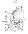
- Patent Document 1 describes, as shown in FIG. 2 , a mechanism which is based on a gimbal mechanism.
- reference numeral 31 denotes the first axis turning mechanism
- 32 denotes the second axis turning mechanism
- 50 denotes the base portion of the apparatus.
- Patent Document 2 European Patent No. EP0919830A2 (Patent Document 2) describes a two-axis turning mechanism that utilizes the profile of the reference sphere 34 and an optical fiber for guiding light.
- reference numeral 31R denotes a ring of the first axis turning mechanism 31 that composes the gimbal mechanism of the two-axis turning mechanism 30, 31M denotes a drive motor thereof, 32R denotes a ring of the second axis turning mechanism 32 that composes the gimbal mechanism of the two-axis turning mechanism 30 and 32M denotes a drive motor thereof.
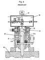
- German Patent Publication No. DE202004007647U1 (Patent Document 3) describes, as shown in FIG. 4 , a two-axis turning mechanism 30 of a three-section structure having (1) a reference sphere supporting portion 40 for supporting the reference sphere, (2) a first axis turning mechanism moving portion 31A that composes the first axis turning mechanism 31, and (3)a first axis turning mechanism fixing portion 31B that composes the first axis turning mechanism 31 as well, and all of which being co-axially disposed from the center (1) a reference sphere supporting portion 40, (2) a first axis turning mechanism moving portion 31A, and (3) a first axis turning mechanism fixing portion 31B.
- the mechanism design adopts a configuration in which both two axes surround the reference sphere 34, wherein the design thereof still remains complex.
- Such a complex mechanism requires a high cost even for only to cause it to be driven as a designed mechanism.
- an optical axis polarization type laser interferometer there may be cases where it becomes necessary for the two-axis turning mechanism 30 to be feedback-controlled in line with movement of a target.
- the mechanism described in Patent Document 3 is further remarkably simplified in comparison with the mechanism designed in Patent Document 2, wherein the first axis and the second axis orthogonal thereto are made clearly separate from each other in the stage of mechanism design.
- the reference sphere supporting portion 40 for supporting the reference sphere 34 is separated from each component of the first axis turning mechanism 31, it is necessary to prepare a long reference sphere supporting portion 40 that passes through the first axis turning mechanism 31 at its center. Since the center coordinate of the reference sphere 34 is an important factor that becomes the measurement reference of an optical axis polarization type laser interferometer, the mechanical stability of the reference sphere supporting portion 40 for supporting the center coordinate is an important specification item in terms of mechanism design. For example, it is necessary that unexpected displacement of the center coordinates of the reference sphere resulting from natural frequencies and thermal expansion is managed within an appropriate range. From this perspective, it cannot be necessarily said that the mechanism design described in Patent Document 3 is optimized.
- the present invention was developed to solve the problems and shortcomings of the prior arts, and it is therefore an object of the present invention to remarkably simplify complexities in mechanism design in regard to the first axis turning mechanism that composes the two-axis turning mechanism.
- an optical axis polarization type laser interferometer including a reference sphere which forms a reference of measurement, a retro-reflecting means disposed at a measurement object, a laser interference measuring apparatus for outputting a measurement value corresponding to an increase or a decrease in the distance to and from the retro-reflecting means, and a two-axis turning mechanism for turning an emission beam of the corresponding laser interference measuring apparatus centering around the reference sphere, which measures, with the center coordinates of the reference sphere used as the reference, the distance to and from the retro-reflecting means where the optical axes of the emission beam from the laser interference measuring apparatus placed on the two-axis turning mechanism and a return beam become parallel to each other, wherein the fixing portion of the first axis turning mechanism installed at the base part of the apparatus is disposed at the inner circumference thereof, the reference sphere is placed at the fixing portion thereof, and at the same time, the moving portion of the first axis turning mechanism is placed at the
- the second axis turning mechanism may have axes each disposed at both sides of the reference sphere with the reference sphere placed therebetween or an axis disposed at one side of the reference sphere.
- the optical axis polarization type laser interferometer may have a displacement gauge for measuring changes in the distance between the laser interference measuring apparatus and the surface of the reference sphere at the opposite side of a measurement light beam thereof.
- the displacement gauge may be an electrostatic capacitance type displacement gauge or an eddy current type displacement gauge.
- a plurality of displacement gauges may be provided.
- the reference sphere may be a metal-made sphere or a metal-coated sphere.
- the present invention may employ a two-section structure including the moving portion of the first axis turning mechanism by rationalizing the three-section structure described in Patent Document 3, integrating the reference sphere supporting portion and the fixing portion of the first axis turning mechanism, and omitting the reference sphere supporting portion being slender and passing through the center portion of the first axis turning mechanism.
- the moving portion of the first axis turning mechanism since the moving portion of the first axis turning mechanism is provided outside, the moving portion may be driven by, for example, a belt from the outside, wherein such unnecessary spacing is not required anymore.
- Embodiment 1 according to the present invention is, as shown in FIG. 5 , such that a fixing portion 31B of the first axis turning mechanism 31 installed at the base portion 50 of an apparatus is disposed at the inner circumference, a reference sphere 34 is disposed thereat via a reference sphere supporting portion 40, and at the same time, a moving portion 31A of the first axis turning mechanism 31 is placed on the outer circumference of the fixing portion 31, and the second axis turning mechanism 32 is mounted thereon.
- reference numeral 60 denotes a displacement gauge that measures changes in the distance between a laser interference measuring apparatus 20 mounted on a carriage 36 and the surface of the reference sphere 34 at the opposite side of the measurement light beam 22.
- a Michelson interferometer may be used as the laser interference measuring apparatus 20.
- the axis 32C of the second axis turning mechanism 32 is divided into two sections with the reference sphere 34 placed therebetween and is located at both sides thereof.
- an electrostatic capacitance type displacement gauge or an eddy current type displacement gauge may be used as the displacement gauge 60. Since these displacement gauges have a large sensor effective area in comparison with the size of dirt and dust, and the horizontal resolution of the sensor is comparatively low, these displacement gauges are less influenced by dirt and dust on the surface of the reference sphere 34.
- a fiber sensor and various types of contact type displacement sensors may be used as the displacement gauge.
- a metal-made sphere that is available on the market may be used as the reference sphere 34.
- the sphere is industrially used and inexpensive.
- the reference sphere 34 may be a ceramic-made, semiconductor-made, glass-made or metal-coated sphere other than the metal-made sphere.
- an eddy-current sensor is used as the displacement gauge, it is necessary that a metal-made or metal-coated sphere is used.
- ⁇ L 1 is a relative displacement (the orientation of which is turned positive (plus) as the distance increases) with respect to the laser interference measuring apparatus 20 and the retro-reflecting means 12, which is measured by using the laser interference measuring apparatus 20, and ⁇ L 2 is a relative displacement (the orientation of which is turned positive (plus) as the distance increases) with respect to the displacement gauge 60 and the surface of the reference sphere 34.
- the displacement gauge 60 is installed between the laser interference measuring apparatus 20 and the reference sphere 34.
- the ⁇ L 1 may be measured by a measurement method based on a publicly known Michelson interferometer in which the retro-reflecting means 12 is made into a measurement object, and the measurement method is referred to in Patent Document 2 and so on. Herein, a detailed description thereof is omitted.
- An automatic tracking method of the retro-reflecting means 12 is the same as that described in Patent Document 2 and so on. Therefore, a description thereof is omitted.
- the second axis turning mechanism 32 has axes 32c each disposed at both sides of the reference sphere 34 with the reference sphere 34 placed therebetween, wherein the stability is high.
- Embodiment 2 of the present invention is a detailed description is given of Embodiment 2 of the present invention.
- a point at which Embodiment 2 differs from Embodiment 1 resides in that the axis 32C of the second axis turning mechanism 32 is provided at one side (the left side in the drawing) of the reference sphere 34. All other points are similar to those of Embodiment 1, and description thereof is omitted.
- the second axis turning mechanism 32 has an axis disposed at one side of the reference sphere 34, another side (the right side in the drawing) of the reference sphere 34 is open, wherein the degree of freedom is high in terms of disposition.
Landscapes
- Physics & Mathematics (AREA)
- Engineering & Computer Science (AREA)
- Electromagnetism (AREA)
- Computer Networks & Wireless Communication (AREA)
- General Physics & Mathematics (AREA)
- Radar, Positioning & Navigation (AREA)
- Remote Sensing (AREA)
- Instruments For Measurement Of Length By Optical Means (AREA)
- Length Measuring Devices By Optical Means (AREA)
- Optical Radar Systems And Details Thereof (AREA)
Abstract
Description
- The present invention relates to an optical axis polarization type laser interferometer including a reference sphere which forms a reference of measurement, a retro-reflecting means disposed at a measurement object, a laser interference measuring apparatus for outputting a measurement value corresponding to an increase or a decrease in the distance to and from the retro-reflecting means, and a two-axis turning mechanism for turning an emission beam of the corresponding laser interference measuring apparatus centering around the reference sphere, which measures, with the center coordinates of the reference sphere used as the reference, the distance to and from the retro-reflecting means where the optical axes of the emission beam from the laser interference measuring apparatus placed on the two-axis turning mechanism and a return beam become parallel to each other. In particular, the invention relates to an optical axis polarization type laser interferometer capable of remarkably simplifying complexities in mechanism design with respect to the first axis turning mechanism that composes the two-axis turning mechanism.
- As shown in
FIG. 1 , an optical axis polarization type laser interferometer (also called a tracking type laser interferometer) has been known, which irradiates a laser beam (called a measurement light beam) 22 from a laserinterference measuring apparatus 20 toward a retro-reflecting means (also called a retro-reflector) 12 disposed at ameasurement object 10, detects a displacement of the retro-reflecting means 12 by utilizing interference of the laser beam reflected in the return direction by the retro-reflecting means 12 and at the same time executes tracking by using a change in the position of the optical axis of themeasurement light beam 22 by the two-axis turning mechanism 30. In the drawing,reference numeral 24 denotes a light source, and 26 denotes a laser beam emitted in the direction completely opposite to a target (12) in order to measure a relative displacement between the surface of thereference sphere 34 installed at the center of the two-axis turning mechanism 30 and the laserinterference measuring apparatus 20.Reference numeral 34 denotes a reference sphere which forms a reference of measurement, 36 denotes a carriage for placing the laserinterference measuring apparatus 20 on the two-axis turning mechanism reference sphere 34. - Thus, in the optical polarization type laser interferometer accompanying the two-
axis turning mechanism 30, it is necessary that aturning mechanism 30 having two axes orthogonal to each other is constructed around thereference sphere 34 that is installed at the center and becomes a measurement reference. However, it is not easy that a simple mechanism of high reliability is achieved with the turning center of the corresponding two-axis turning mechanism 30 aligned with the center of thereference sphere 34. - For example, Japanese Patent No.
2603429 FIG. 2 , a mechanism which is based on a gimbal mechanism. In the drawing,reference numeral 31 denotes the first axis turning mechanism, 32 denotes the second axis turning mechanism, and 50 denotes the base portion of the apparatus. - Also, as shown in
FIG. 3 , European Patent No.EP0919830A2 (Patent Document 2) describes a two-axis turning mechanism that utilizes the profile of thereference sphere 34 and an optical fiber for guiding light. In the drawing,reference numeral 31R denotes a ring of the firstaxis turning mechanism 31 that composes the gimbal mechanism of the two-axis turning mechanism axis turning mechanism 32 that composes the gimbal mechanism of the two-axis turning mechanism - In addition, German Patent Publication No.
DE202004007647U1 (Patent Document 3) describes, as shown inFIG. 4 , a two-axis turning mechanism 30 of a three-section structure having (1) a referencesphere supporting portion 40 for supporting the reference sphere, (2) a first axis turningmechanism moving portion 31A that composes the firstaxis turning mechanism 31, and (3)a first axis turningmechanism fixing portion 31B that composes the firstaxis turning mechanism 31 as well, and all of which being co-axially disposed from the center (1) a referencesphere supporting portion 40, (2) a first axis turningmechanism moving portion 31A, and (3) a first axis turningmechanism fixing portion 31B. - However, since the two-axis turning mechanism described in Patent Document 1 guides light by means of a beam bender as means for guiding light of the laser
interference measuring apparatus 20 to the two-axis turning mechanism 30, it is necessary that a considerably complex mechanism design is carried out only for the sake of guiding light from the light source. - Also in Patent Document 2, the mechanism design adopts a configuration in which both two axes surround the
reference sphere 34, wherein the design thereof still remains complex. In particular, it is necessary to control the laser interference measuring apparatus via tworings interference measuring apparatus 20. Such a complex mechanism requires a high cost even for only to cause it to be driven as a designed mechanism. Further, in the case of an optical axis polarization type laser interferometer, there may be cases where it becomes necessary for the two-axis turning mechanism 30 to be feedback-controlled in line with movement of a target. In this case, it is necessary to minimize non-linear phenomena such as friction, backlash, etc., which pose a risk of adversely influencing the control, in the stage of mechanism design, wherein the cost is further increased. Therefore, as far as the art according to Patent Document 2 is concerned, this necessitates that a remarkably high cost design is executed in terms of industrial aspect. - On the other hand, the mechanism described in
Patent Document 3 is further remarkably simplified in comparison with the mechanism designed in Patent Document 2, wherein the first axis and the second axis orthogonal thereto are made clearly separate from each other in the stage of mechanism design. However, since the referencesphere supporting portion 40 for supporting thereference sphere 34 is separated from each component of the firstaxis turning mechanism 31, it is necessary to prepare a long referencesphere supporting portion 40 that passes through the firstaxis turning mechanism 31 at its center. Since the center coordinate of thereference sphere 34 is an important factor that becomes the measurement reference of an optical axis polarization type laser interferometer, the mechanical stability of the referencesphere supporting portion 40 for supporting the center coordinate is an important specification item in terms of mechanism design. For example, it is necessary that unexpected displacement of the center coordinates of the reference sphere resulting from natural frequencies and thermal expansion is managed within an appropriate range. From this perspective, it cannot be necessarily said that the mechanism design described inPatent Document 3 is optimized. - That is, it is not realistic that the installation environment of the optical axis polarization type laser interferometer is remarkably strictly restricted. Therefore, if it temporarily attempts to reduce unexpected displacement resulting from thermal expansion of the reference
sphere supporting portion 40, adoption of a material whose coefficient of thermal expansion is low is taken into consideration. Generally, the mechanical feature of a material having a low coefficient of thermal expansion, in particular, the specific rigidity influencing the resonance frequency is low in comparison with mechanical structure materials. It is required that the referencesphere supporting portion 40 according toPatent Document 3 is shaped to be slender, the length-to-width ratio of which is large, wherein it is difficult that the mechanism design is optimized from this perspective. - Further, since the weight of the second axis, an interferometer, and a displacement gauge, which are supported by the first
axis turning mechanism 31, is increased, it is necessary to achieve an economical design while satisfying required functions such as turning accuracy, weight, etc. - The present invention was developed to solve the problems and shortcomings of the prior arts, and it is therefore an object of the present invention to remarkably simplify complexities in mechanism design in regard to the first axis turning mechanism that composes the two-axis turning mechanism.
- The present invention solves the above-described problems and shortcomings by means of an optical axis polarization type laser interferometer including a reference sphere which forms a reference of measurement, a retro-reflecting means disposed at a measurement object, a laser interference measuring apparatus for outputting a measurement value corresponding to an increase or a decrease in the distance to and from the retro-reflecting means, and a two-axis turning mechanism for turning an emission beam of the corresponding laser interference measuring apparatus centering around the reference sphere, which measures, with the center coordinates of the reference sphere used as the reference, the distance to and from the retro-reflecting means where the optical axes of the emission beam from the laser interference measuring apparatus placed on the two-axis turning mechanism and a return beam become parallel to each other, wherein the fixing portion of the first axis turning mechanism installed at the base part of the apparatus is disposed at the inner circumference thereof, the reference sphere is placed at the fixing portion thereof, and at the same time, the moving portion of the first axis turning mechanism is placed at the outer circumference of the fixing portion, and the second axis turning mechanism is mounted on the moving portion thereof.
- The second axis turning mechanism may have axes each disposed at both sides of the reference sphere with the reference sphere placed therebetween or an axis disposed at one side of the reference sphere.
- The optical axis polarization type laser interferometer may have a displacement gauge for measuring changes in the distance between the laser interference measuring apparatus and the surface of the reference sphere at the opposite side of a measurement light beam thereof.
- The displacement gauge may be an electrostatic capacitance type displacement gauge or an eddy current type displacement gauge.
- A plurality of displacement gauges may be provided.
- The reference sphere may be a metal-made sphere or a metal-coated sphere.
- The present invention may employ a two-section structure including the moving portion of the first axis turning mechanism by rationalizing the three-section structure described in
Patent Document 3, integrating the reference sphere supporting portion and the fixing portion of the first axis turning mechanism, and omitting the reference sphere supporting portion being slender and passing through the center portion of the first axis turning mechanism. As a result, with the present invention, mechanism design, parts machining, and assembling adjustment may be simply and easily carried out, wherein low-cost production may be achieved, and a further compact mechanism may be brought about. - In addition, in the prior art shown in, for example,
FIG. 4 , it was necessary to provide unnecessary spacing to drive the moving portion positioned relatively internally. However, according to the present invention, since the moving portion of the first axis turning mechanism is provided outside, the moving portion may be driven by, for example, a belt from the outside, wherein such unnecessary spacing is not required anymore. - These and other novel features and advantages of the present invention will become apparent from the following detailed description of preferred embodiments.
- The preferred embodiments will be described with reference to the drawings, wherein like elements have been denoted throughout the figures with like reference numerals, and wherein;
-
FIG. 1 is an optical path diagram showing one example of an optical system of a prior art optical axis polarization type laser interferometer; -
FIG. 2 is a perspective view showing a configuration of a two-axis turning mechanism of the optical axis polarization type laser interferometer described in Patent Document 1; -
FIG. 3 is a perspective view showing a configuration of a two-axis turning mechanism of the optical axis polarization type laser interferometer described in Patent Document 2; -
FIG. 4 is a sectional view showing a configuration of a two-axis turning mechanism of the optical axis polarization type laser interferometer described inPatent Document 3; -
FIG. 5 is a sectional view showing a configuration of Embodiment 1 according to the present invention; -
FIG. 6 is a sectional view showing a configuration of Embodiment 2 according to the present invention; and -
FIG. 7 is a perspective view showing major components ofEmbodiment 3 according to the present invention. - Preferred exemplary embodiments of the present invention will now be described in detail, with respect to the drawings.
- Hereinafter, a detailed description is given of embodiments of the present invention with reference to the drawings.
- Embodiment 1 according to the present invention is, as shown in
FIG. 5 , such that afixing portion 31B of the firstaxis turning mechanism 31 installed at thebase portion 50 of an apparatus is disposed at the inner circumference, areference sphere 34 is disposed thereat via a referencesphere supporting portion 40, and at the same time, a movingportion 31A of the firstaxis turning mechanism 31 is placed on the outer circumference of thefixing portion 31, and the secondaxis turning mechanism 32 is mounted thereon. - In the drawing,
reference numeral 60 denotes a displacement gauge that measures changes in the distance between a laserinterference measuring apparatus 20 mounted on acarriage 36 and the surface of thereference sphere 34 at the opposite side of themeasurement light beam 22. - For example, a Michelson interferometer may be used as the laser
interference measuring apparatus 20. - The
axis 32C of the secondaxis turning mechanism 32 is divided into two sections with thereference sphere 34 placed therebetween and is located at both sides thereof. - For example, an electrostatic capacitance type displacement gauge or an eddy current type displacement gauge may be used as the
displacement gauge 60. Since these displacement gauges have a large sensor effective area in comparison with the size of dirt and dust, and the horizontal resolution of the sensor is comparatively low, these displacement gauges are less influenced by dirt and dust on the surface of thereference sphere 34. In addition, a fiber sensor and various types of contact type displacement sensors may be used as the displacement gauge. - For example, a metal-made sphere that is available on the market may be used as the
reference sphere 34. The sphere is industrially used and inexpensive. Also, thereference sphere 34 may be a ceramic-made, semiconductor-made, glass-made or metal-coated sphere other than the metal-made sphere. However, where an eddy-current sensor is used as the displacement gauge, it is necessary that a metal-made or metal-coated sphere is used. - In the embodiment, a change (displacement) ΔL in the length between a
fixed reference sphere 34, the position of which is used as a reference point, and the retro-reflecting means 12 is calculated by the following expression.
- Herein, ΔL1 is a relative displacement (the orientation of which is turned positive (plus) as the distance increases) with respect to the laser
interference measuring apparatus 20 and the retro-reflectingmeans 12, which is measured by using the laserinterference measuring apparatus 20, and ΔL2 is a relative displacement (the orientation of which is turned positive (plus) as the distance increases) with respect to thedisplacement gauge 60 and the surface of thereference sphere 34. Thedisplacement gauge 60 is installed between the laserinterference measuring apparatus 20 and thereference sphere 34. - Since the distance from the surface of a highly
accurate reference sphere 34 to the center of thereference sphere 34 is fixed at high accuracy, it is possible to highly accurately measure the displacement of the retro-reflectingmeans 12 with the center of thereference sphere 34 used as reference even if the firstaxis turning mechanism 31 and the secondaxis turning mechanism 32 turn centering around the center of thereference sphere 34. - The ΔL1 may be measured by a measurement method based on a publicly known Michelson interferometer in which the retro-reflecting
means 12 is made into a measurement object, and the measurement method is referred to in Patent Document 2 and so on. Herein, a detailed description thereof is omitted. - An automatic tracking method of the retro-reflecting
means 12 is the same as that described in Patent Document 2 and so on. Therefore, a description thereof is omitted. - In the embodiment, the second
axis turning mechanism 32 has axes 32c each disposed at both sides of thereference sphere 34 with thereference sphere 34 placed therebetween, wherein the stability is high. - Next, referring to
FIG. 6 , a detailed description is given of Embodiment 2 of the present invention. - A point at which Embodiment 2 differs from Embodiment 1 resides in that the
axis 32C of the secondaxis turning mechanism 32 is provided at one side (the left side in the drawing) of thereference sphere 34. All other points are similar to those of Embodiment 1, and description thereof is omitted. - Since, in the present embodiment, the second
axis turning mechanism 32 has an axis disposed at one side of thereference sphere 34, another side (the right side in the drawing) of thereference sphere 34 is open, wherein the degree of freedom is high in terms of disposition. - Since either one of the embodiments described above is provided with a
single displacement gauge 60, the configuration is simple. Also, as inEmbodiment 3 shown inFIG. 7 based on the case ofFIG. 6 , if a plurality of displacement gauges (in the drawings, twodisplacement gauges 60a and 60b) are provided, it is possible to compensate a temperature drift, etc., in the output of the displacement gauges. Herein, it is important that a plurality of displacement gauges 60a and 60b are disposed at both sides of thereference sphere 34, and the optical axis of the interferometer is aligned with the displacement gauges on the same line.
Claims (7)
- An optical axis polarization type laser interferometer, comprising:a reference sphere which forms a reference of measurement;a retro-reflecting means disposed at a measurement object;a laser interference measuring apparatus for outputting a measurement value corresponding to an increase or a decrease in the distance to and from the retro-reflecting means; anda two-axis turning mechanism for turning an emission beam of the corresponding laser interference measuring apparatus centering around the reference sphere,which measures, with the center coordinates of the reference sphere used as the reference, the distance to and from the retro-reflecting means where the optical axes of the emission beam from the laser interference measuring apparatus placed on the two-axis turning mechanism and a return beam become parallel to each other,wherein the fixing portion of the first axis turning mechanism installed at the base part of the apparatus is disposed at the inner circumference thereof, the reference sphere is placed at the fixing portion thereof, and at the same time, the moving portion of the first axis turning mechanism is placed at the outer circumference of the fixing portion, and the second axis turning mechanism is mounted on the moving portion thereof.
- The optical axis polarization type interferometer according to Claim 1, wherein the second axis turning mechanism has axes each disposed at both sides of the reference sphere with the reference sphere placed therebetween.
- The optical axis polarization type interferometer according to Claim 1, wherein the second axis turning mechanism has an axis disposed at one side of the reference sphere.
- The optical axis polarization type interferometer according to Claim 1, further including a displacement gauge for measuring changes in the distance between the laser interference measuring apparatus and the surface of the reference sphere at the opposite side of the measurement light beam thereof.
- The optical axis polarization type interferometer according to Claim 4, wherein the displacement gauge is an electrostatic capacitance type displacement gauge or an eddy current type displacement gauge.
- The optical axis polarization type interferometer according to Claim 4, wherein a plurality of displacement gauges are provided.
- The optical axis polarization type interferometer according to Claim 1, wherein the reference sphere is a metal-made sphere or a metal-coated sphere.
Applications Claiming Priority (1)
| Application Number | Priority Date | Filing Date | Title |
|---|---|---|---|
| JP2007037410A JP2008203015A (en) | 2007-02-19 | 2007-02-19 | Optical axis deflection laser interferometer |
Publications (2)
| Publication Number | Publication Date |
|---|---|
| EP1959226A2 true EP1959226A2 (en) | 2008-08-20 |
| EP1959226A3 EP1959226A3 (en) | 2012-12-05 |
Family
ID=39477568
Family Applications (1)
| Application Number | Title | Priority Date | Filing Date |
|---|---|---|---|
| EP08002673A Withdrawn EP1959226A3 (en) | 2007-02-19 | 2008-02-13 | Optical axis polarization type laser interferometer |
Country Status (3)
| Country | Link |
|---|---|
| US (1) | US7599070B2 (en) |
| EP (1) | EP1959226A3 (en) |
| JP (1) | JP2008203015A (en) |
Cited By (3)
| Publication number | Priority date | Publication date | Assignee | Title |
|---|---|---|---|---|
| DE102010032407B3 (en) * | 2010-06-29 | 2011-12-15 | Bundesrepublik Deutschland, vertr. durch d. Bundesministerium f. Wirtschaft und Technologie, dieses vertreten durch d. Präsidenten d. Physikalisch-Technischen Bundesanstalt | Three-dimensional laser-length measuring system for neodymium-doped yttrium vanadate laser, has light sources providing laser lights, which are focused on reflector, where beam adjusting device directs laser beam toward retroreflector |
| CN112113509A (en) * | 2019-06-20 | 2020-12-22 | 上海微电子装备(集团)股份有限公司 | Gantry measuring device and gantry measuring method |
| EP4513228A1 (en) | 2023-08-25 | 2025-02-26 | Hexagon AICON ETALON GmbH | Tracking instrument with rigid optical measurement unit and coupled reference element |
Families Citing this family (3)
| Publication number | Priority date | Publication date | Assignee | Title |
|---|---|---|---|---|
| JP5250286B2 (en) * | 2008-03-27 | 2013-07-31 | 株式会社ミツトヨ | Tracking laser interferometer |
| JP5933190B2 (en) * | 2010-06-30 | 2016-06-08 | ドクトル・ヨハネス・ハイデンハイン・ゲゼルシヤフト・ミツト・ベシユレンクテル・ハフツングDr. Johannes Heidenhain Gesellschaft Mit Beschrankter Haftung | Optical distance measuring device |
| TWI595252B (en) | 2016-05-10 | 2017-08-11 | 財團法人工業技術研究院 | Distance measurement device and distance measuring method thereof |
Citations (3)
| Publication number | Priority date | Publication date | Assignee | Title |
|---|---|---|---|---|
| JP2603429B2 (en) | 1993-10-25 | 1997-04-23 | 工業技術院長 | Tracking laser interferometer |
| EP0919830A2 (en) | 1997-10-17 | 1999-06-02 | The Secretary of State for Trade and Industry of Her Majesty's Britannic Government | Tracking system |
| DE202004007647U1 (en) | 2004-05-10 | 2004-08-12 | Bundesrepublik Deutschland, vertr. d. d. Bundesministerium für Wirtschaft und Arbeit, dieses vertr. d. d. Präsidenten der Physikalisch-Technischen Bundesanstalt | Laser interferometer for spacing measurement has reference sphere positioned on post and base plate made of thermally invariant material |
Family Cites Families (10)
| Publication number | Priority date | Publication date | Assignee | Title |
|---|---|---|---|---|
| DE4218379C2 (en) | 1992-06-04 | 1995-04-13 | Dirk Tillich | Device for the separation of suspended matter in flowing liquids |
| US5757474A (en) * | 1993-05-10 | 1998-05-26 | Midwest Research Institute | System for characterizing semiconductor materials and photovoltaic devices through calibration |
| GB9401692D0 (en) * | 1994-01-28 | 1994-03-23 | Renishaw Plc | Performing measurement or calibration on positioning machines |
| JPH09243573A (en) * | 1996-03-12 | 1997-09-19 | Furukawa Electric Co Ltd:The | Surface inspection equipment |
| US6563569B2 (en) * | 2000-09-25 | 2003-05-13 | Agency Of Industrial Science & Technology, Ministry Of International Trade & Industry | Laser tracking interferometric length measuring instrument and method of measuring length and coordinates using the same |
| EP1750085B1 (en) * | 2005-07-26 | 2013-07-31 | Mitutoyo Corporation | Laser tracking interferometer |
| JP4776454B2 (en) * | 2005-07-26 | 2011-09-21 | 株式会社ミツトヨ | Tracking laser interferometer |
| JP4776473B2 (en) * | 2006-08-25 | 2011-09-21 | 株式会社ミツトヨ | Optical axis deflection laser interferometer, its calibration method, correction method, and measurement method |
| JP4771898B2 (en) * | 2006-09-04 | 2011-09-14 | 株式会社ミツトヨ | Laser interference tracking length measuring method and apparatus |
| JP5244339B2 (en) * | 2007-06-20 | 2013-07-24 | 株式会社ミツトヨ | Tracking laser interferometer and recovery method of tracking laser interferometer |
-
2007
- 2007-02-19 JP JP2007037410A patent/JP2008203015A/en active Pending
-
2008
- 2008-02-13 EP EP08002673A patent/EP1959226A3/en not_active Withdrawn
- 2008-02-14 US US12/031,335 patent/US7599070B2/en active Active
Patent Citations (3)
| Publication number | Priority date | Publication date | Assignee | Title |
|---|---|---|---|---|
| JP2603429B2 (en) | 1993-10-25 | 1997-04-23 | 工業技術院長 | Tracking laser interferometer |
| EP0919830A2 (en) | 1997-10-17 | 1999-06-02 | The Secretary of State for Trade and Industry of Her Majesty's Britannic Government | Tracking system |
| DE202004007647U1 (en) | 2004-05-10 | 2004-08-12 | Bundesrepublik Deutschland, vertr. d. d. Bundesministerium für Wirtschaft und Arbeit, dieses vertr. d. d. Präsidenten der Physikalisch-Technischen Bundesanstalt | Laser interferometer for spacing measurement has reference sphere positioned on post and base plate made of thermally invariant material |
Cited By (4)
| Publication number | Priority date | Publication date | Assignee | Title |
|---|---|---|---|---|
| DE102010032407B3 (en) * | 2010-06-29 | 2011-12-15 | Bundesrepublik Deutschland, vertr. durch d. Bundesministerium f. Wirtschaft und Technologie, dieses vertreten durch d. Präsidenten d. Physikalisch-Technischen Bundesanstalt | Three-dimensional laser-length measuring system for neodymium-doped yttrium vanadate laser, has light sources providing laser lights, which are focused on reflector, where beam adjusting device directs laser beam toward retroreflector |
| CN112113509A (en) * | 2019-06-20 | 2020-12-22 | 上海微电子装备(集团)股份有限公司 | Gantry measuring device and gantry measuring method |
| CN112113509B (en) * | 2019-06-20 | 2022-06-17 | 上海微电子装备(集团)股份有限公司 | Gantry measuring device and gantry measuring method |
| EP4513228A1 (en) | 2023-08-25 | 2025-02-26 | Hexagon AICON ETALON GmbH | Tracking instrument with rigid optical measurement unit and coupled reference element |
Also Published As
| Publication number | Publication date |
|---|---|
| US7599070B2 (en) | 2009-10-06 |
| US20080198387A1 (en) | 2008-08-21 |
| EP1959226A3 (en) | 2012-12-05 |
| JP2008203015A (en) | 2008-09-04 |
Similar Documents
| Publication | Publication Date | Title |
|---|---|---|
| EP1892500B1 (en) | Laser interferometer and method of its calibration and use | |
| US7388674B2 (en) | Laser tracking interferometer | |
| US9074865B2 (en) | Contour and surface texture measuring instrument and contour and surface texture measuring method | |
| KR100863983B1 (en) | Sheet thickness or expansion measurement method and apparatus | |
| US7599070B2 (en) | Optical axis polarization type laser interferometer | |
| US6646750B1 (en) | Method and arrangement for measuring the structures of an object | |
| JP3400393B2 (en) | Laser interference device | |
| JP5193490B2 (en) | Measuring method using tracking laser interferometer | |
| US6543149B1 (en) | Coordinate measuring system | |
| EP2638369B1 (en) | Dual input interferometer beamsplitter tilt control system and flexure mounting | |
| US20100182611A1 (en) | Displacement measuring apparatus and displacement measuring method | |
| KR102871123B1 (en) | Shape measuring apparatus, reference device, calibration method of a detector | |
| US20170167860A1 (en) | Measurement apparatus and measurement method | |
| JP2000055617A (en) | Optical length measuring machine | |
| JP2012181021A (en) | Contact type probe and shape measurement device | |
| JP3532347B2 (en) | Shape measuring device | |
| EP2638371B1 (en) | Flexure mounted moving mirror to reduce vibration noise | |
| KR101890314B1 (en) | Laser tracker | |
| JP2007155401A (en) | Displacement sensor and shape measuring apparatus | |
| JP3239094B2 (en) | Athletic body posture control device | |
| JP3795646B2 (en) | Position measuring device | |
| JP2014025756A (en) | Position detector | |
| JP2008051525A (en) | Displacement sensor, table driving device including displacement sensor, and driving method thereof | |
| JPH02184704A (en) | Length measuring instrument | |
| NL2015307B1 (en) | Optoelectronic Linear Position Sensor and wheel truing indicating instrument. |
Legal Events
| Date | Code | Title | Description |
|---|---|---|---|
| PUAI | Public reference made under article 153(3) epc to a published international application that has entered the european phase |
Free format text: ORIGINAL CODE: 0009012 |
|
| AK | Designated contracting states |
Kind code of ref document: A2 Designated state(s): AT BE BG CH CY CZ DE DK EE ES FI FR GB GR HR HU IE IS IT LI LT LU LV MC MT NL NO PL PT RO SE SI SK TR |
|
| AX | Request for extension of the european patent |
Extension state: AL BA MK RS |
|
| PUAL | Search report despatched |
Free format text: ORIGINAL CODE: 0009013 |
|
| AK | Designated contracting states |
Kind code of ref document: A3 Designated state(s): AT BE BG CH CY CZ DE DK EE ES FI FR GB GR HR HU IE IS IT LI LT LU LV MC MT NL NO PL PT RO SE SI SK TR |
|
| AX | Request for extension of the european patent |
Extension state: AL BA MK RS |
|
| RIC1 | Information provided on ipc code assigned before grant |
Ipc: G01S 17/66 20060101ALI20121030BHEP Ipc: G01S 7/481 20060101AFI20121030BHEP |
|
| AKY | No designation fees paid | ||
| REG | Reference to a national code |
Ref country code: DE Ref legal event code: R108 Effective date: 20130814 |
|
| STAA | Information on the status of an ep patent application or granted ep patent |
Free format text: STATUS: THE APPLICATION IS DEEMED TO BE WITHDRAWN |
|
| 18D | Application deemed to be withdrawn |
Effective date: 20130606 |