EP1959202A2 - Thermostatic control device for radiator valves - Google Patents
Thermostatic control device for radiator valves Download PDFInfo
- Publication number
- EP1959202A2 EP1959202A2 EP08001502A EP08001502A EP1959202A2 EP 1959202 A2 EP1959202 A2 EP 1959202A2 EP 08001502 A EP08001502 A EP 08001502A EP 08001502 A EP08001502 A EP 08001502A EP 1959202 A2 EP1959202 A2 EP 1959202A2
- Authority
- EP
- European Patent Office
- Prior art keywords
- locking ring
- control knob
- thermostatic
- support body
- valve
- Prior art date
- Legal status (The legal status is an assumption and is not a legal conclusion. Google has not performed a legal analysis and makes no representation as to the accuracy of the status listed.)
- Withdrawn
Links
- 230000002093 peripheral effect Effects 0.000 claims description 9
- 238000005452 bending Methods 0.000 claims description 3
- 238000010438 heat treatment Methods 0.000 description 11
- 230000001276 controlling effect Effects 0.000 description 5
- 239000012530 fluid Substances 0.000 description 5
- 230000001105 regulatory effect Effects 0.000 description 4
- 230000002596 correlated effect Effects 0.000 description 1
- 230000008878 coupling Effects 0.000 description 1
- 238000010168 coupling process Methods 0.000 description 1
- 238000005859 coupling reaction Methods 0.000 description 1
- 239000000463 material Substances 0.000 description 1
- 230000004048 modification Effects 0.000 description 1
- 238000012986 modification Methods 0.000 description 1
- 230000000007 visual effect Effects 0.000 description 1
Images


Classifications
-
- F—MECHANICAL ENGINEERING; LIGHTING; HEATING; WEAPONS; BLASTING
- F24—HEATING; RANGES; VENTILATING
- F24D—DOMESTIC- OR SPACE-HEATING SYSTEMS, e.g. CENTRAL HEATING SYSTEMS; DOMESTIC HOT-WATER SUPPLY SYSTEMS; ELEMENTS OR COMPONENTS THEREFOR
- F24D19/00—Details
- F24D19/10—Arrangement or mounting of control or safety devices
- F24D19/1006—Arrangement or mounting of control or safety devices for water heating systems
- F24D19/1009—Arrangement or mounting of control or safety devices for water heating systems for central heating
- F24D19/1015—Arrangement or mounting of control or safety devices for water heating systems for central heating using a valve or valves
- F24D19/1018—Radiator valves
-
- G—PHYSICS
- G05—CONTROLLING; REGULATING
- G05D—SYSTEMS FOR CONTROLLING OR REGULATING NON-ELECTRIC VARIABLES
- G05D23/00—Control of temperature
- G05D23/01—Control of temperature without auxiliary power
- G05D23/02—Control of temperature without auxiliary power with sensing element expanding and contracting in response to changes of temperature
- G05D23/021—Control of temperature without auxiliary power with sensing element expanding and contracting in response to changes of temperature the sensing element being a non-metallic solid, e.g. elastomer, paste
- G05D23/023—Control of temperature without auxiliary power with sensing element expanding and contracting in response to changes of temperature the sensing element being a non-metallic solid, e.g. elastomer, paste the sensing element being placed outside a regulating fluid flow
Landscapes
- Engineering & Computer Science (AREA)
- Physics & Mathematics (AREA)
- Thermal Sciences (AREA)
- Chemical & Material Sciences (AREA)
- Combustion & Propulsion (AREA)
- Mechanical Engineering (AREA)
- General Engineering & Computer Science (AREA)
- Fluid Mechanics (AREA)
- General Physics & Mathematics (AREA)
- Automation & Control Theory (AREA)
- Temperature-Responsive Valves (AREA)
Abstract
A thermostatic control device for controlling radiator valves (10). The device comprises a support body (15) having elastically yielding clamping members (18) to engage with the body (12) of the valve (10), by a locking ring (27) axially slidable pivotingly locking ring (27) rotatably supported by the body (15) of the device. A control knob (31), screwably engaged by the support body (15), houses a thermostatic actuator (35) for a closing member of the valve. The control knob (31) and the locking ring (27) comprise engageable and disengageable hooking means (29, 38) for selectively locking the rotation of the control knob (31) in a plurality of angular positions, by the simple rotation of the locking ring (27).
Description
- This invention refers to a settable thermostatic control device for regulating and operating radiator valves for heating systems, and in particular relates to a manually operable thermostatic control head for flow control valves of the aforementioned type.
- In heating systems for civil and/or industrial buildings, it is necessary to make use of appropriate thermostatic devices for controlling and regulating the room temperature, which can be fitted onto the radiator elements of the heating system. To this purpose, it is well-known that the temperature of an environment depends on the presence of radiator elements, and can be affected by natural or other types of external heat sources.
- In modern heating systems, in order to obtain an adequate comfort and an appropriate differentiated control of the temperature in the various environments, in relation to different requirements of users, it is necessary to provide the individual radiator elements with thermostatically actuated valves suitable for controlling the circulation of the thermal fluid and for automatically regulating the temperature of the body of the radiator, also enabling an user to change and/or preset the heating temperature at a pre-established value.
- In this connection, the flow control valves are usually provided with a thermostatic control device, sensitive to the room temperature, which is capable of operating a valve closing device, for adjusting the flow of the thermal fluid which is made to circulate in a heating plant.
- Usually, a thermostatic head comprises a body for supporting a rotatable knob housing an extensible thermostatic actuator sensitive to the room temperature; the thermostatic actuator is operatively connected to a control rod of a plug or closing member of the radiator valve and, as the room temperature varies, the thermostatic actuator axially extends or reduces its length, consequently varying the open and closed conditions of the flow control valve. By manually operating and rotating a control knob in one or in an opposite direction with respect to the support body, a user can change and regulate the operative temperature at will, and consequently the heating temperature of the environment.
- Thermostatic heads or devices of this type are described for example in
US-A-4.089.461 ,US-A-4.290.553 ,EP-A-32112 EP-A-1.359.489 . - One of the problems inherent in the known type of thermostatic heads consists in the difficulty of adjusting and locking the thermostatic head in the adjusted operative conditions appropriately selectable by the user, due to the complexity of the control system.
- In general, this is achieved by locking the rotation of the knob by variously conformed locking devices, which functionally and structurally complicate the thermostatic head itself, thereby making this operation somewhat difficult to carry out.
- A second problem, resulting from the previous one, concerns the need to provide the thermostatic head with anti-tampering means for preventing any tampering of the thermostatic head which is liable to jeopardise its correct working.
- The main object of this invention is to provide a thermostatically actuated control device for radiator valves or for heating elements, by means of which it is possible to obviate the aforementioned drawbacks.
- A particular object of the invention is to provide a thermostatically actuated valve control device for controlling the circulation of a thermal fluid in radiators, whereby it is possible to automatically regulate opening and closing conditions of the control valve, in relation to a room heating temperature, to maintain the same heating temperature at a substantially constant value, and to selectively adjust the required temperature by a solution structurally simple and easy to be set by an user, and at the same time preventing any risk of tampering with the thermostatic device itself.
- A further object of the invention is to provide a thermostatic device of the aforementioned kind, conformed to allow a quick coupling to a valve, and to stop the rotation of a control knob by easily operating a single locking device.
- These and further objects of the invention can be achieved by a thermostatic control device for radiator valves and the like, according to claim 1.
- In particular, according to the invention, a thermostatic device has been provided, for a radiator valve having a valve body and an axially movable closing member, the thermostatic device comprising:
- a cup-shaped support body having a peripheral wall, and a bottom wall provided with elastically yieldable clamping members conformed to bent and to engage with the valve body;
- an axially movable locking ring for bending and engaging said clamping members with the valve body;
- a control knob screwably engaged with the support body of the thermostatic device; and
- a thermostatic actuator inside the control knob, the thermostatic actuator having an axially movable rod operatively connected to the closing device of the radiator valve,
- These and further characteristics and objects of the thermostatic control device according to the invention, will be more clearly evident from the following description of one of its preferential embodiments, and from the drawings, in which:
-
Figure 1 shows a radiator valve provided with a thermostatic control device according to the invention; -
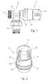
Figure 2 shows a perspective view of the thermostatic device; -
Figure 3 shows an exploded view of the thermostatic device; -
Figure 4 shows a longitudinal cross-sectional view of the control knob; -
Figure 5 shows a longitudinal cross-sectional view of the support body, along the line 5-5 offigure 6 ; -
Figure 6 shows a top view of the support body, along the line 6-6 offigure 5 ; -
Figure 7 shows a longitudinal cross-sectional view of the locking ring; -
Figure 8 shows a longitudinal cross-sectional view of the thermostatic control device, in an assembled condition; -
Figure 9 shows a cross-sectional view along the line 9-9 offigure 8 , with the knob free to rotate; -
Figure 10 shows a cross-sectional view also along the line 9-9 offigure 8 , with the knob in a locked condition; -
Figure 11 shows stop means preventing the knob from becoming completely unscrewed and removed from the support body of the control device. -
Figure 1 shows avalve 10 for regulating the flow of a thermal fluid fed to a radiator or similar heating element, whilereference number 11 indicates an automatic thermostatic control device for controlling thevalve 10. - The
valve 10 comprises abody 12 having aninlet 13 for the fluid, axially aligned with thethermostatic device 11, and alateral outlet 14. Thevalve 10, in a per se known way, for example as shown inUS 4.089.461 comprises a plug or similar flow closing member, thrust by a spring to close against a seat inside thebody 12; the plug has astem 26,figure 8 , that axially extends towards thethermostatic device 11, operatively connected to the latter to move the plug or closing member in respect to the valve seat, depending on the room temperature sensed by a thermostatic actuator inside thecontrol device 11. - As shown in
figures 2 and5 , and in the exploded view offigure 3 , thethermostatic device 11 comprises a cup-shaped support body 15 having aperipheral wall 16 provided with an internal screw thread, for example a multi-start screw thread, and abottom wall 17 having a central aperture for the passage of a control member for thevalve 10, as explained further on. - The
support body 15, in correspondence with the central aperture in thebottom wall 17, extends with four elasticallyyieldable clamping members 18 conformed to engage thebody 12 of thevalve 10; eachclamping member 18 is provided with an internal rib orteeth 19 to engage acircumferential groove 20 in thevalve body 12, as shown infigure 8 . - The
support body 15 also comprises aseat 21 for housing thehead 22 of acylindrical sleeve 23 for housing acounter spring 24 acting on a slidingrod 25 axially aligned with thestem 26 of the plug of thevalve 10, as shown infigure 8 . - The
thermostatic device 11 also comprises amovable locking ring 27 axially slidable and rotatably supported by thebody 15 of thecontrol device 11. - The
locking ring 27, in correspondence with thetooth 19 of theclamping members 18, is provided with anannular ribbing 28,figures 7 and8 which, following a forward sliding movement of thering 27, inwardly bends theclamping members 18 to engage thetooth 19 into thegroove 20 of thevalve body 15; theannular ribbing 28 in turn penetrates intoside slots 18' of the clampingmembers 18 to prevent disengagement. - The
locking ring 27 and acontrol knob 31, as shown infigures 3 and7 , are provided with engageable and disengageable retaining means to selectively lock the rotation of theknob 31 in a plurality of angularly spaced apart stop positions; in the example shown, the stop means comprises a bar-shaped and elasticallyflexible hooking member 29 on thering 27, and retaining elements or recessedportions 39 on thecontrol knob 31, as will be explained further on; astop member 30 is provided on thesame locking ring 27 for stopping the rotation of theknob 31 preventing it from being completely unscrewed; once again, thestop member 30 is in the form of a bar which extends parallely to and on the opposite side of the hookingmember 29, to partially protrude from the rear edge of thelocking ring 27, as shown infigure 3 , to engage with aninternal rib 36 of theknob 31, as shown infigure 9 . - The
control knob 31, as shown in the various figures, is provided with acylindrical wall portion 32 having anexternal screw thread 33 designed to be screwed into theinternal screw thread 16 of the cylindrical wall portion of thesupport body 15 of thecontrol device 11;slits 34 enable the passage of air from the environment towards the inside of theknob 31. - A per se known
thermostatic actuator 35, for example of wax type or other type is housed inside theknob 31; thethermostatic actuator 35 is capable of varying its volume, that is to say of axially extending and retracting as the room temperature changes, to push thesleeve 23 with thepin 25 against thestem 26 of the plug member of thevalve 10, or to allow it to move backwards. - The
knob 31 in turn comprises aninternal rib 36 which longitudinally extends parallel to thestop member 30 of thelocking ring 27, therib 36 being capable to rest against thestop member 30 to stop the rotation of theknob 31, preventing it from being completely unscrewed. - The
knob 31, inside its front edge, is provided with a plurality ofrecesses 38, or angularly spaced apart retaining elements designed to be selectively engaged and disengaged by the hookingmember 29 of thering 27, by an angular rotation of the same knob. - In this connection, the
bottom wall 17 of thebody 15 is provided in opposite positions with twoarched slots members locking ring 27; the arch shapedslots locking ring 27, for releasing and, respectively, locking the rotation of theknob 31. - In particular, the
slot 40 for the hookingmember 29 has its internal edge provided with cam means comprising a first radially backwardcam portion 41A, and asecond cam portion 41B radially advanced with respect to thecam portion 41A; thecam portions slot 40, performs the function of laterally bending the hookingmember 29, allowing the same hookingmember 29 to engage and, respectively, disengage from arecess 38 of theknob 31 that has been selectively positioned, by rotation of thesame knob 31, in relation to a desired operative temperature of thethermostatic control device 11. - The foregoing is more clearly explained by
figures 9 and 10 ; more precisely,figure 9 shows the disengaged condition of the hookingmember 29 when thelocking ring 27 is rotated to present the backwardcam portion 41A of theslot 40 in correspondence with theaforesaid hooking member 29. In this condition, theknob 31 is disengaged and is free to rotate. - Conversely,
figure 10 shows a locked condition of theknob 31, following a rotation of thelocking ring 27. - In this condition, the radially
advanced cam portion 41B of theslot 40 pushes the elastic hookingmember 29 into arecess 38 of theknob 31 which at that given moment is radially aligned to the hookingmember 29, depending on the rotation of thesame knob 31; in each of its variously selectable angular positions ofrecesses 38, the rotation of theknob 31 is therefore prevented. - Lastly,
figure 11 schematically shows a second solution of the means for stopping the rotation of theknob 31, preventing it from being unscrewed completely and disengaged from thesupport body 15. - According to this solution, the
wall 32 of theknob 31 is provided with an internal tooth orprotrusion 43 to engage with a similar external tooth orprotrusion 42 on thesupport body 15. - The
thermostatic device 11 is completed by a scale 0 and by anindex 44 for selectable temperatures correlated to the positions of therecesses 38, to provide a visual indication of a preset temperature. In particular theknob 31 is provided on the outer surface ofcylindrical wall 32 with a circumferential temperature scale 0, while the peripheral wall of thebody 15 is provided with areference index 44 in correspondence with arecess 45 or a lateral window on the peripheral edge. - From what has been described and shown in the accompanying drawings, it will be evident therefore that a structurally simple thermostatic control device for radiator valves has been provided, in which, by means of two simple movements of a locking ring, one in the axial and the other one or rotational direction, it is possible to clamp the thermostatic device to the valve body and, respectively, lock the rotation of the knob, selectively in several pre-established angular positions, each of which corresponds to a preset room temperature, for controlling and partially or totally closing the radiator valve.
- It is understood that what has been described and shown in the accompanying drawings has been given purely by way of example in order to illustrate the general features of the invention and a preferential embodiment of the thermostatic device.
- In particular, it is pointed out that the various parts of the thermostatic device, such as the
body 15, the lockingring 27 and theknob 31 can be manufactured and moulded from any suitable plastic material, either of a same or of different types, provided they are suitable for the intended use. - Therefore, other modifications and/or variations may be made to the device in its entirety, and to one or more component parts, without thereby departing from the claims.
in that the control knob and the locking ring comprise engageable and disengageable hooking means to lock the rotation of the control knob,
said hooking means comprising an elastically flexible hooking member selectively engageable with and disengageable from angularly spaced apart retaining elements on the control knob, and cam means on the support body to engage and disengage the hooking member upon angular rotation of the locking ring.
Claims (9)
- Thermostatic device (11) for a radiator valve (10) having a valve body (12) and an axially movable closing member, the thermostatic device (11) comprising:a cup-shaped support body (15) having a peripheral wall (16), and a bottom wall (17) provided with elastically yieldable clamping members (18) conformed to bent and to engage with the valve body (12);an axially movable locking ring (27) for bending and engaging said clamping members (18) with the valve body (12);a control knob (31) screwably engaged with the support body (15) of the thermostatic device (11); anda thermostatic actuator (35) inside the control knob (11), the thermostatic actuator (35) having an axially movable rod (25) operatively connected to the closing device of the radiator valve (10),characterised in that the locking ring (27) is rotatably supported by the cup-shaped body (15) of the control device; and
in that the control knob (31) and the locking ring (27) comprise engageable and disengageable hooking means (29, 38) to lock the rotation of the control knob (31),
said hooking means (29, 38) comprising an elastically flexible hooking member (29) selectively engageable with and disengageable from angularly spaced apart retaining elements (38) on the control knob (31), and cam means (41A, 41B) on the support body (15) to engage and disengage the hooking member (29) upon angular rotation of the locking ring (27). - The thermostatic device according to claim 1, characterised in that said hooking means (29, 38) comprise an elastically flexible hooking member (29) protruding into the locking ring (27), said hooking member (29) selectively engaging with a plurality of angularly spaced apart retaining elements (38) inside the control knob (31).
- The thermostatic device according to claim 2, characterised in that said hooking member (29) is in the form of a bar-shaped member which extends parallel to a rotational axis of the locking ring (27).
- The thermostatic device according to claim 2, characterised in that said retaining elements (38) are consisting in a plurality of recessed areas on an edge of the control knob (31).
- The thermostatic device according to claim 1, characterised by comprising interengaging stop means (30, 36) on locking ring (27) and the control knob (31), to prevent the same control knob (31) from becoming completely unscrewed from the support body (15).
- The thermostatic device according to claim 5, characterised in that the stop means comprises stop members (30, 36) parallely extending to a rotational axis of locking ring (27).
- The thermostatic device according to claim 5, characterised in that the stop means comprises an internal protrusion (43) on the peripheral wall (32) of the knob (15), and an external protrusion (42) on the peripheral wall of the support body (15).
- The thermostatic device according to claim 1, characterised by comprising a scale (0) for settable temperatures on the control knob (31), and a reference index (44) on the support body (15).
- A thermostatic control unit for controlling a radiator valve (10), in which the valve (10) comprises a body (12) having a seating for an axially movable closing member, characterised by comprising:a cup-shaped support body (15), having peripheral and bottom walls provided with a central aperture, at least one arch shaped slot (10) coaxially arranged to said central aperture, and a plurality of clamping members (18) for the valve body (12), which extend from the bottom wall of the support body (15);a control knob (31) screwably engaged with the cup-shaped support body (15);a thermostatic actuator (35) inside the control knob (31), said thermostatic actuator (35) being operatively connected to the closing member of the radiator valve;a locking ring (27) axially movable and rotatably supported with respect to a longitudinal axis of the support body (15);said locking ring (27) comprising an annular rib (28), engageable with said clamping members (18) upon an axial movement of the locking ring (27);the locking ring (27) comprising a hooking member in the form of an elastically flexible bar-shaped element (29) which extends parallel to a longitudinal axis of the support body (15), said bar-shaped element (29) extending through said arch-shaped slot (40) in the bottom wall of the support body (15);a plurality of angularly spaced apart retaining elements (38) inside a peripheral wall (32) of the control knob (31), said retaining elements (38) being selectively engageable by said hooking member (29); andcam means (41A, 41B) on an edge of said arch-shaped slot (40), to selectively engage said hooking member (29) with the retaining elements (38) of the control knob (31), upon rotation of the locking ring (27).
Applications Claiming Priority (1)
| Application Number | Priority Date | Filing Date | Title |
|---|---|---|---|
| IT000265A ITMI20070265A1 (en) | 2007-02-13 | 2007-02-13 | THERMOSTATIC CONTROL HEAD FOR RADIATOR VALVES |
Publications (1)
| Publication Number | Publication Date |
|---|---|
| EP1959202A2 true EP1959202A2 (en) | 2008-08-20 |
Family
ID=39494239
Family Applications (1)
| Application Number | Title | Priority Date | Filing Date |
|---|---|---|---|
| EP08001502A Withdrawn EP1959202A2 (en) | 2007-02-13 | 2008-01-28 | Thermostatic control device for radiator valves |
Country Status (2)
| Country | Link |
|---|---|
| EP (1) | EP1959202A2 (en) |
| IT (1) | ITMI20070265A1 (en) |
Cited By (7)
| Publication number | Priority date | Publication date | Assignee | Title |
|---|---|---|---|---|
| US7617989B2 (en) * | 2005-04-26 | 2009-11-17 | Caleffi S.P.A. | Automatically reclosable thermostatic control device for valves |
| EP2264344A1 (en) * | 2009-06-16 | 2010-12-22 | Georg Fischer Rohrleitungssysteme AG | Element for preventing unauthorised unscrewing |
| US20140199055A1 (en) * | 2011-08-25 | 2014-07-17 | I.R.C.A. S.P.A. Industria Resistenze Corazzate E Affini | Hydronic/biphasic radiator with reduced thermal inertia and low environmental impact |
| GB2528629A (en) * | 2014-04-23 | 2016-02-03 | Robert Williamn Lunn | Thermostatic radiator valve clamp |
| EP3193065A1 (en) * | 2016-01-15 | 2017-07-19 | Danfoss A/S | Valve, in particular heat exchanger valve |
| EP3193064A1 (en) * | 2016-01-15 | 2017-07-19 | Danfoss A/S | Valve |
| US10006642B2 (en) | 2014-05-09 | 2018-06-26 | Jerritt L. Gluck | Systems and methods for controlling conditioned fluid systems in a built environment |
Citations (4)
| Publication number | Priority date | Publication date | Assignee | Title |
|---|---|---|---|---|
| US4089461A (en) | 1976-07-06 | 1978-05-16 | Braukmann Armaturen A.G. | Thermostatic radiator valve |
| EP0032112A1 (en) | 1980-01-07 | 1981-07-15 | Manfred Luik | Thermostat device for valve control |
| US4290553A (en) | 1979-05-28 | 1981-09-22 | Danfoss A/S | Rotary knob for thermostatic valves of radiators |
| EP1359489A2 (en) | 2002-04-24 | 2003-11-05 | Fracchia, Stefano | Device for selecting the operating mode of control heads in particular for thermostatic valves |
-
2007
- 2007-02-13 IT IT000265A patent/ITMI20070265A1/en unknown
-
2008
- 2008-01-28 EP EP08001502A patent/EP1959202A2/en not_active Withdrawn
Patent Citations (4)
| Publication number | Priority date | Publication date | Assignee | Title |
|---|---|---|---|---|
| US4089461A (en) | 1976-07-06 | 1978-05-16 | Braukmann Armaturen A.G. | Thermostatic radiator valve |
| US4290553A (en) | 1979-05-28 | 1981-09-22 | Danfoss A/S | Rotary knob for thermostatic valves of radiators |
| EP0032112A1 (en) | 1980-01-07 | 1981-07-15 | Manfred Luik | Thermostat device for valve control |
| EP1359489A2 (en) | 2002-04-24 | 2003-11-05 | Fracchia, Stefano | Device for selecting the operating mode of control heads in particular for thermostatic valves |
Cited By (15)
| Publication number | Priority date | Publication date | Assignee | Title |
|---|---|---|---|---|
| US7617989B2 (en) * | 2005-04-26 | 2009-11-17 | Caleffi S.P.A. | Automatically reclosable thermostatic control device for valves |
| EP2264344A1 (en) * | 2009-06-16 | 2010-12-22 | Georg Fischer Rohrleitungssysteme AG | Element for preventing unauthorised unscrewing |
| WO2010145964A1 (en) * | 2009-06-16 | 2010-12-23 | Georg Fischer Rohrleitungssysteme Ag | Securing element for securing against unauthorized unscrewing |
| CN102483174A (en) * | 2009-06-16 | 2012-05-30 | 乔治费希尔管路系统公开股份有限公司 | Securing element for securing against unauthorized unscrewing |
| US8672599B2 (en) | 2009-06-16 | 2014-03-18 | Georg Fischer Rohrleitungssysteme Ag | Securing element for securing against unauthorized unscrewing |
| CN102483174B (en) * | 2009-06-16 | 2016-08-03 | 乔治费希尔管路系统公开股份有限公司 | Prevent the undelegated safety element turned on |
| US9829251B2 (en) * | 2011-08-25 | 2017-11-28 | I.R.C.A. S.P.A. Industria Resistenze Corazzate E Affini | Hydronic/biphasic radiator with reduced thermal inertia and low environmental impact |
| US20140199055A1 (en) * | 2011-08-25 | 2014-07-17 | I.R.C.A. S.P.A. Industria Resistenze Corazzate E Affini | Hydronic/biphasic radiator with reduced thermal inertia and low environmental impact |
| GB2528629A (en) * | 2014-04-23 | 2016-02-03 | Robert Williamn Lunn | Thermostatic radiator valve clamp |
| US10006642B2 (en) | 2014-05-09 | 2018-06-26 | Jerritt L. Gluck | Systems and methods for controlling conditioned fluid systems in a built environment |
| EP3193064A1 (en) * | 2016-01-15 | 2017-07-19 | Danfoss A/S | Valve |
| CN106979345A (en) * | 2016-01-15 | 2017-07-25 | 丹佛斯有限公司 | Valve |
| EP3193065A1 (en) * | 2016-01-15 | 2017-07-19 | Danfoss A/S | Valve, in particular heat exchanger valve |
| RU2655898C1 (en) * | 2016-01-15 | 2018-05-29 | Данфосс А/С | Valve |
| CN106979345B (en) * | 2016-01-15 | 2019-04-09 | 丹佛斯有限公司 | Valve |
Also Published As
| Publication number | Publication date |
|---|---|
| ITMI20070265A1 (en) | 2008-08-14 |
Similar Documents
| Publication | Publication Date | Title |
|---|---|---|
| EP1959202A2 (en) | Thermostatic control device for radiator valves | |
| DK168239B1 (en) | Mixer battery, especially for domestic water | |
| EP3265886B1 (en) | Mixing valve assembly and tap provided with said valve assembly | |
| US5230465A (en) | Control knob for a thermostatically regulated valve | |
| EP1359489B1 (en) | Device for selecting the operating mode of control heads in particular for thermostatic valves | |
| EP1701235B1 (en) | Control head for a thermostatic valve | |
| EP0903525A2 (en) | Control device for thermostatic valves | |
| DK155550B (en) | CONTROL VALVE, INSERT A THERMOSTATICALLY CONTROLLED VALVE | |
| US5251811A (en) | Temperature-setting system for thermostatic mixing valve | |
| US5242108A (en) | Control knob for thermostatically regulated mixing valve | |
| EP2857920B1 (en) | A thermostatic head for a valve | |
| WO2009026922A2 (en) | A thermostat | |
| WO2006080036A1 (en) | Device to control a fluid flow | |
| JPH0520635B2 (en) | ||
| EP0775954A1 (en) | Thermostatic mixing tap | |
| CN211315207U (en) | Thermostatic valve and water heater with same | |
| EP3627021B1 (en) | Valve with rotatable presetting element | |
| JP3740666B2 (en) | Hot and cold water mixing faucet with thermostat | |
| EP3193065B1 (en) | Valve, in particular heat exchanger valve | |
| CN220727303U (en) | Side-outlet thermostatic valve | |
| EP2738639B1 (en) | Thermostatic valve actuator | |
| CZ2000774A3 (en) | Control apparatus for thermostatic valve adapter | |
| EP2487396B1 (en) | Lockshield unit for check valves in heating systems | |
| CN210266015U (en) | Thermostatic valve | |
| JPH06331058A (en) | Automatic temperature adjusting combination faucet device |
Legal Events
| Date | Code | Title | Description |
|---|---|---|---|
| PUAI | Public reference made under article 153(3) epc to a published international application that has entered the european phase |
Free format text: ORIGINAL CODE: 0009012 |
|
| AK | Designated contracting states |
Kind code of ref document: A2 Designated state(s): AT BE BG CH CY CZ DE DK EE ES FI FR GB GR HR HU IE IS IT LI LT LU LV MC MT NL NO PL PT RO SE SI SK TR |
|
| AX | Request for extension of the european patent |
Extension state: AL BA MK RS |
|
| STAA | Information on the status of an ep patent application or granted ep patent |
Free format text: STATUS: THE APPLICATION IS DEEMED TO BE WITHDRAWN |
|
| 18D | Application deemed to be withdrawn |
Effective date: 20130801 |