EP1959197A2 - Combustor of a gas turbine - Google Patents
Combustor of a gas turbine Download PDFInfo
- Publication number
- EP1959197A2 EP1959197A2 EP20080151392 EP08151392A EP1959197A2 EP 1959197 A2 EP1959197 A2 EP 1959197A2 EP 20080151392 EP20080151392 EP 20080151392 EP 08151392 A EP08151392 A EP 08151392A EP 1959197 A2 EP1959197 A2 EP 1959197A2
- Authority
- EP
- European Patent Office
- Prior art keywords
- fuel
- combustion
- mixture
- air
- combustor
- Prior art date
- Legal status (The legal status is an assumption and is not a legal conclusion. Google has not performed a legal analysis and makes no representation as to the accuracy of the status listed.)
- Withdrawn
Links
Images



Classifications
-
- F—MECHANICAL ENGINEERING; LIGHTING; HEATING; WEAPONS; BLASTING
- F23—COMBUSTION APPARATUS; COMBUSTION PROCESSES
- F23R—GENERATING COMBUSTION PRODUCTS OF HIGH PRESSURE OR HIGH VELOCITY, e.g. GAS-TURBINE COMBUSTION CHAMBERS
- F23R3/00—Continuous combustion chambers using liquid or gaseous fuel
- F23R3/28—Continuous combustion chambers using liquid or gaseous fuel characterised by the fuel supply
- F23R3/286—Continuous combustion chambers using liquid or gaseous fuel characterised by the fuel supply having fuel-air premixing devices
-
- F—MECHANICAL ENGINEERING; LIGHTING; HEATING; WEAPONS; BLASTING
- F23—COMBUSTION APPARATUS; COMBUSTION PROCESSES
- F23R—GENERATING COMBUSTION PRODUCTS OF HIGH PRESSURE OR HIGH VELOCITY, e.g. GAS-TURBINE COMBUSTION CHAMBERS
- F23R3/00—Continuous combustion chambers using liquid or gaseous fuel
- F23R3/28—Continuous combustion chambers using liquid or gaseous fuel characterised by the fuel supply
- F23R3/34—Feeding into different combustion zones
- F23R3/343—Pilot flames, i.e. fuel nozzles or injectors using only a very small proportion of the total fuel to insure continuous combustion
-
- F—MECHANICAL ENGINEERING; LIGHTING; HEATING; WEAPONS; BLASTING
- F23—COMBUSTION APPARATUS; COMBUSTION PROCESSES
- F23R—GENERATING COMBUSTION PRODUCTS OF HIGH PRESSURE OR HIGH VELOCITY, e.g. GAS-TURBINE COMBUSTION CHAMBERS
- F23R3/00—Continuous combustion chambers using liquid or gaseous fuel
- F23R3/42—Continuous combustion chambers using liquid or gaseous fuel characterised by the arrangement or form of the flame tubes or combustion chambers
- F23R3/50—Combustion chambers comprising an annular flame tube within an annular casing
-
- F—MECHANICAL ENGINEERING; LIGHTING; HEATING; WEAPONS; BLASTING
- F23—COMBUSTION APPARATUS; COMBUSTION PROCESSES
- F23C—METHODS OR APPARATUS FOR COMBUSTION USING FLUID FUEL OR SOLID FUEL SUSPENDED IN A CARRIER GAS OR AIR
- F23C2900/00—Special features of, or arrangements for combustion apparatus using fluid fuels or solid fuels suspended in air; Combustion processes therefor
- F23C2900/07022—Delaying secondary air introduction into the flame by using a shield or gas curtain
-
- F—MECHANICAL ENGINEERING; LIGHTING; HEATING; WEAPONS; BLASTING
- F23—COMBUSTION APPARATUS; COMBUSTION PROCESSES
- F23D—BURNERS
- F23D2900/00—Special features of, or arrangements for burners using fluid fuels or solid fuels suspended in a carrier gas
- F23D2900/00008—Burner assemblies with diffusion and premix modes, i.e. dual mode burners
Definitions
- the present invention relates to a combustor for use in a gas turbine engine including a fuel injection structure of a composite combustion type comprising a combination of two combustion systems, i.e., a diffusion combustion system and a lean pre-mixture combustion system.
- the composite combustion system can ensure the stability of combustion, while starting the operation and/or operating under lower intensity combustion, due to its diffusion combustion region, while it can reduce the amount of generation of the NOx, under higher intensity combustion, due to its lean pre-mixture combustion region.
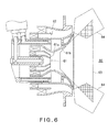
- a combustor for the composite combustion system includes a fuel spray portion 61 adapted to spray a fuel so as to form the diffusion combustion region, due to the diffusion combustion system, in a combustion chamber 60, and a pre-mixture supply portion 62 shaped concentrically relative to the fuel spray portion 61 to surround the outer circumference of the fuel spray portion 61, and adapted for supplying a pre-mixture of a fuel and air so as to form the pre-mixture combustion region, due to the lean pre-mixture combustion system, in the combustion chamber 60.
- the combustor is configured to supply a fuel only from the fuel spray portion 61 while starting the operation and/or operating under a lower intensity combustion mode, whereas, on a higher intensity combustion mode, it supplies the fuel also from the pre-mixture supply portion 62, in addition to supplying of the fuel from the fuel spray portion 61.
- the fuel spray portion 61 includes a fuel atomizing portion 61a, which is adapted to change the fuel into particles suitable for combustion by utilizing shearing force of air, and a diffusion passage portion 61b disposed on the downstream side of the fuel atomizing portion 61a, adapted to reduce the speed of a mixture of the fuel and air to a speed suitable for the combustion, and having a spreading trumpet-like shape. In this case, it is intended to enhance the combustion efficiency, due to the diffusion combustion to be achieved by spreading the diffusion combustion region, by utilizing the diffusion passage portion 61b.
- diffusion combustion flame 63 is created by a mixed gas or mixture of the fuel and air introduced to spread over the entire space in the combustion chamber 60 along the diffusion passage portion 61b having a spreading trumpet-like shape.
- the air 64 to be supplied from the pre-mixture supply portion 62 will interfere with the outer circumferential region of the so-created diffusion combustion flame 63.
- the interferential range between the diffusion combustion flame 63 and the air 64 is schematically depicted in Fig.
- the present invention was made in light of the above challenges posed on the conventional art, and it is therefore an object thereof to provide a combustor for use in the gas turbine engine, the combustor having a structure of a composite combustion system comprising a combination of the two combustion systems, i.e., the diffusion combustion system and the lean pre-mixture combustion system, and being able to securely enhance the ignition performance, the flame holding performance, and the stability of combustion under lower intensity combustion.
- the combustor of a gas turbine engine including: a fuel spray portion configured to spray a fuel so as to create a diffusion combustion region in a combustion chamber; a pre-mixture supply portion configured to supply a pre-mixture gas including the fuel and an air so as to create a pre-mixture combustion region in the combustion chamber, the pre-mixture supply portion being positioned concentrically with the fuel spray portion so as to surround the fuel spray portion; and an annular separation portion disposed between a downstream end of the fuel spray portion and a downstream end of the pre-mixture supply portion so as to separate the diffusion combustion region and the pre-mixture combustion region from each other.
- only the air may be supplied from the pre-mixture supply portion into the diffusion combustion region while starting an operation of the engine and/or operating the engine under low intensity combustion.
- the diffusion combustion region and the pre-mixture combustion region can be separated from each other due to the annular separation portion disposed between the fuel spray portion and the pre-mixture supply portion. Therefore, while starting the operation and/or operating under lower intensity combustion, the diffusion combustion flame generated by the fuel injected from the fuel spray portion into the combustion chamber will not be mixed with a great amount of air supplied from the pre-mixture supply portion. Consequently, flame failure of the diffusion combustion flame due to the great amount of the air can be prevented, while the entire diffusion combustion region can be kept within a fuel concentration range suitable for stable combustion, thereby the ignition performance, flame holding performance and stable combustion can be significantly ensured under a lower intensity combustion mode.
- the combustor of a gas turbine engine further comprises air curtain forming means configured to inject a separating air between the diffusion combustion region and the pre-mixture combustion region through the annular separation portion so as to promote a separation between the regions.
- the air curtain can prevent, further effectively, the fuel supplied from the fuel spray portion from being mixed with the air to be used for the pre-mixture combustion, and the separating air can surely cool the separation portion to be exposed to the combustion flame.
- the annular separation portion has a width W in a radial direction
- the pre-mixture supply portion includes an outer circumferential wall having an inner diameter D at a downstream end thereof, the width W being set between 0.13D to 0.25D. If the width W in the radial direction of the separation portion is less than 0.13D, the diffusion combustion region and the pre-mixture combustion region can not be effectively separated from each other, due to such a separation portion. Contrary, if the width W in the radial direction exceeds 0.25D, the diffusion combustion region would be too small. Thus the fuel would be injected focusing on the narrowed region, as such making the fuel not likely to be combusted, resulting in deterioration of the stability of combustion.
- the fuel spray portion includes a fuel atomizing portion configured to atomize the fuel, and a diffusion passage portion disposed downstream of the fuel atomizing portion, the diffusion passage portion having a spreading trumpet-like shape and being configured to diffuse the fuel and the air.
- the diffusion combustion region and the pre-mixture combustion region can be separated from each other due to the separation portion disposed between the fuel spray portion and the pre-mixture supply portion. Therefore, mixing of the great amount of air supplied from the pre-mixture supply portion with the diffusion combustion flame created by the fuel supplied from the fuel spray portion can be prevented, while starting the operation and/or operating under lower intensity combustion. Consequently, flame failure of the diffusion combustion flame caused by such air can be avoided, while the entire diffusion combustion region can be kept in a fuel concentration range suitable for stable combustion, thereby the ignition performance, flame holding performance and stability of combustion can be significantly enhanced under a lower intensity combustion mode.
- Fig. 1 shows a head of a combustor 1 for use in a gas turbine engine according to a first embodiment of the present invention.
- the combustor 1 is configured to drive a turbine, by combusting a mixed gas or mixture to be formed by mixing a fuel with compressed air supplied from a compressor (not shown) of the gas turbine engine, and then supplying the so-formed high-temperature and high-pressure combustion gas generated by the combustion to the turbine.
- the combustor 1 is of an annular type, in which a combustor housing 6 having an annular internal space is constructed by arranging an annular inner casing 8 concentrically into an annular outer casing 7.
- a combustion cylinder 9 which is constructed by arranging an annular inner liner 11 concentrically into an annular outer liner 10, is arranged concentrically with the combustor housing 6.
- the combustion cylinder 9 has an annular combustion chamber 12 formed therein.
- a plurality of (fourteen (14) in this embodiment) fuel injection units 2 each adapted to inject the fuel into the combustion chamber 12 are positioned concentrically with the combustion cylinder 9 at an equal interval, while arranged in a single circle.
- Each fuel injection unit 2 includes a fuel spray portion (pilot fuel injection nozzle) 3, and a pre-mixture supply portion (main fuel injection nozzle) 4 configured to surround the outer circumference of the fuel spray portion 3 and arranged concentrically with the fuel spray portion 3.
- the fuel spray portion 3 and pre-mixture supply portion 4 will be detailed later.
- two spark plugs 13 adapted for ignition extend in the radial direction relative to the combustion cylinder 9, with the distal ends thereof being opposed to the fuel injection units 2. Accordingly, in the combustor 1, the combustible mixed gas injected from the two fuel injection units 2 opposed to the two spark plugs 13 is first ignited, and the flame generated due to the combustion then burns the combustible mixed gas injected from adjacent fuel injection units 2, after another. Finally, the flame transfers to and ignites the mixed gas injected from all the fuel injection units 2.
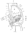
- Fig. 2 is an enlarged longitudinal section taken along line II-II of Fig. 1 .
- compressed air CA supplied from the compressor is introduced via a plurality of air intake pipes 14.
- the compressed air CA introduced is then supplied into the fuel injection unit 2, while supplied into the combustion chamber 12 through air introduction ports 17 respectively formed in large numbers in the outer liner 10 and inner liner 11 of the combustion cylinder 9.
- a fuel piping unit 18, constituting a first fuel supply system F1 for supplying a fuel for diffusion combustion into the fuel spray portion 3 and a second fuel supply system F2 for supplying a fuel for lean pre-mixture combustion into the pre-mixture supply portion 4, is supported by the outer casing 7, and is connected with a base 19 of the combustion cylinder 9.
- Each fuel injection unit 2 is supported by the outer liner 10 via a flange 5A disposed on the outer circumferential portion of the fuel injection unit 2 and a support member 5B disposed on the outer liner 10.
- the outer liner 10 is in turn supported by the outer casing 7 via a liner fixing pin P.
- a first stage nozzle TN of the turbine is connected with a downstream end of the combustion cylinder 9.
- Fig. 3 is a longitudinal section showing the fuel injection unit 2 of Fig. 2 in more detail.
- the fuel spray portion 3 disposed at a central portion of the fuel injection unit 2 includes a cylindrical main body 20 having a bottom portion and adapted to supply the fuel F, for the diffusion combustion, fed from the first fuel supply system F1, a cylindrical inner circumferential wall 21 fitted around the main body 20, a cylindrical intermediate wall 22 arranged externally and concentrically relative to the cylindrical inner circumferential wall 21, a nozzle 23 of a Venturi nozzle type, arranged externally and concentrically relative to the cylindrical intermediate wall 22, a first inner swirler 24 disposed between the cylindrical inner circumferential wall 21 and the cylindrical intermediate wall 22, and a first outer swirler 27 disposed between the cylindrical intermediate wall 22 and the nozzle 23.
- a plurality of fuel injection holes 25 are formed radially to inject radially outward the fuel F supplied into the main body 20.
- a fuel introduction hole 26 is formed for introducing the fuel F into a primary atomizing passage 28 formed between the cylindrical inner circumferential wall 21 and the cylindrical intermediate wall 22.
- the fuel F introduced into the primary atomizing passage 28 is then injected from an atomized fuel injection port 28a disposed on the downstream side.
- the atomized fuel injection port 28a i.e., the downstream end of each of the cylindrical inner circumferential wall 21 and cylindrical intermediate wall 22 is substantially coincident, in position along the axis of the combustor 1 (in the lateral direction in the drawing), with a throttling portion 23a, at which the inner diameter of the nozzle 23 is the minimum.
- a diameter spreading portion 23b extending downstream from the throttling portion 23a of the nozzle 23 is formed into a trumpet-like shape having a predetermined spreading angle.
- the fuel spray portion 3 includes a fuel atomizing portion 3a defined by a portion extending from an upstream end of the nozzle 23 up to the throttling portion 23a of the nozzle 23, and a diffusion passage portion 3b defined by a portion extending from the throttling portion 23a up to a downstream end of the nozzle 23, i.e., the diameter spreading portion 23b of the nozzle 23.
- the fuel atomizing portion 3a includes respective downstream ends 21a, 22a of the cylindrical inner circumferential wall 21 and cylindrical intermediate wall 22 constituting the primary atomizing passage 28.
- the downstream ends 21a, 22a are each formed into a tapered truncated conical shape, corresponding to the shape in the opposite position of the nozzle 23.
- the fuel atomizing portion 3a is configured to inject the fuel F from the primary atomizing passage 28 and the compressed air CA from the first outer swirler 27, respectively, toward the central axis of the main body 20, obliquely, in a layered state. Thereafter, the diffusion passage portion 3b disposed downstream of the fuel atomizing portion 3a injects the fuel F and the compressed air CA into the combustion chamber 12 at an injection angle defined by the diameter spreading portion 23b while diffusing the fuel F together with the compressed air CA.
- the fuel F for the diffusion combustion is supplied from the first fuel supply system F1 in all the range of load or intensity, i.e., from the stage while starting the operation and/or operating under lower intensity combustion (50% or lower relative to the full load) up to the stage under higher intensity combustion (50% or higher relative to the full load).
- the fuel F supplied into the main body 20 is injected from each fuel injection hole 25, and the injected fuel F is then subjected to primary atomization due to the compressed air CA supplied from the first inner swirler 24.
- the fuel F having been subjected to the primary atomization is further subjected to secondary atomization due to a swirling air stream provided from the first outer swirler 27 in the diffusion passage portion 3b, thus being sprayed into the combustion chamber 12, as such creating a diffusion combustion region 50 in the combustion chamber 12.
- the pre-mixture supply portion 4 includes a cylindrical double-wall main body 29 including an inner cylindrical body 30 and an outer cylindrical body 31, a cylindrical intermediate wall 32 arranged externally and concentrically relative to the main body 29, a cylindrical outer circumferential wall 33 arranged externally and concentrically relative to the cylindrical intermediate wall 32, a cylindrical partition wall 34 for separating the cylindrical intermediate wall 32 from the cylindrical outer circumferential wall 33, a second inner swirler 38 located at an input port of a pre-mixture preparing chamber 37 disposed between the cylindrical intermediate wall 32 and the cylindrical partition wall 34, and a second outer swirler 39 disposed between the cylindrical partition wall 34 and the cylindrical outer circumferential wall 33.
- the main body 29 is supported by the base 19, externally to the fuel spray portion 3, with the opening at an upstream end between the cylindrical double walls of the main body 29 being closed by a cover-like portion 40 of the base 19.
- the fuel F, for the pre-mixture combustion, supplied from the second fuel supply system F2 can be introduced into the pre-mixture supply portion 4.
- a fuel supply passage 41 is formed in a gap between the inner cylindrical body 30 and the outer cylindrical body 31.
- the fuel supply passage 41 is configured to supply the fuel F fed from the second fuel supply system F2 to a plurality of (for example, eight) fuel injection holes 35 respectively formed in the downstream circumferential wall of the outer cylindrical body 31 at a predetermined interval.
- fuel introduction holes 36 for guiding the fuel F injected from the respective fuel injection holes 35 into the pre-mixture preparing chamber 37, are formed.
- the cylindrical intermediate wall 32 covers approximately a half of the downstream part of the outer cylindrical body 31, and the downstream end of the wall 32 is coincident, in the axial position, with the downstream end of the nozzle 23 of the fuel spray portion 3.
- a pre-mixture chamber 42 is disposed on the downstream side of the cylindrical partition wall 34 and between the cylindrical intermediate wall 32 and the cylindrical outer circumferential wall 33.
- the upstream end of the cylindrical partition wall 34 is coincident, in the axial position, with the upstream end of the cylindrical intermediate wall 32.
- the length in the axial direction of the cylindrical partition wall 34 is set such that its downstream end is located downstream a predetermined distance relative to the fuel introduction hole 36.
- the upstream end of the cylindrical outer circumferential wall 33 is positioned downstream in the axial direction a predetermined distance relative to the upstream end of the cylindrical partition wall 34.
- the down stream end of the cylindrical outer circumferential wall 33 is set to be coincident, in the axial position, with the downstream end of the cylindrical intermediate wall 32.
- the fuel F is supplied from the second fuel supply system F2 only under higher intensity combustion as is greater than 50% or more relative to the full load.
- the fuel F is then injected into the pre-mixture preparing chamber 37, via the fuel injection holes 35 and the fuel introduction holes 36, through the fuel supply passage 41. Thereafter, the injected fuel F is subjected to the primary atomization due to the compressed air CA supplied from the second inner swirler 38. Subsequently, the fuel F having been subjected to the primary atomization is further subjected to the second atomization due to the swirling air stream provided from the second outer swirler 39 in the pre-mixture chamber 42.
- the pre-mixture gas is produced, in which the fuel F and the compressed air CA are well mixed in advance.
- the pre-mixture gas is then supplied and combusted in the combustion chamber 12, thereby a pre-mixture combustion region 51 is created. It should be noted that since the fuel F is not supplied into the pre-mixture supply portion 4 under a lower intensity combustion mode as is lower than 50% or less relative to the full load, only a greater amount of the compressed air CA is supplied into the combustion chamber 12 in that mode.
- annular separation portion 43 is disposed between the downstream end of the nozzle 23 of the fuel spray portion 3 and the downstream end of the cylindrical intermediate wall 32 of the pre-mixture supply portion 4.
- the separation portion 43 is adapted to separate the diffusion combustion region 50 created due to the fuel spray portion 3 from the pre-mixture combustion region 51 created due to the pre-mixture supply portion 4.
- the separation portion 43 includes an annular cover member 44 arranged to close a space defined between the respective downstream ends of the nozzle 23 and cylindrical intermediate wall 32, while separating these downstream ends from each other in the radial direction.
- a downstream face of the cover member 44 opposed to the combustion chamber 12 is a flat face extending along the radial direction.
- An annular end member 45 is attached between the downstream end of the nozzle 23 and the downstream end of the cylindrical intermediate wall 32, and a plurality of air holes 46 are formed in the end member 45 along the circumferential direction at an equal interval. Between the cover member 44 and the end member 45, an air passage 47 communicating with each air hole 46 is formed. Additionally, an annular air injection port 48 communicating with the air passage 47 is disposed between the inner circumferential face of the cover member 44 and the downstream end of the diameter spreading portion 23b of the nozzle 23. An air accumulation chamber 49 is formed between the nozzle 23 and the cylindrical intermediate wall 32, and each air hole 46 is in communication with the air accumulation chamber 49.
- an air curtain forming means 55 is constructed, by the air holes 46, air passage 47 and air injection port 48, the air curtain means 55 being adapted to inject the compressed air CA accumulated in the air accumulation chamber 49, as the separation air SA, between the diffusion combustion region 50 and the pre-mixture combustion region 51, through the separation portion 43, so as to promote the separation between the regions 50, 51.
- the fuel F is supplied only to the fuel spray portion 3 located inside the fuel injection unit 2 from the first fuel supply system F1, and the fuel F is then diffused, together with the compressed air CA, by the diffusion passage portion 3b having a spreading trumpet-like shape in the fuel spray portion 3. Thereafter, the diffused mixture is injected into the combustion chamber while spreading, as such being likely to be combusted and thus providing excellent stability of combustion in the diffusion combustion region 50. At this time, spreading of the stream of the fuel F to be injected into the combustion chamber 12 from the diffusion passage portion 3b can be properly controlled. Consequently, as schematically shown in Fig.
- the diffusion combustion region 50 can be properly separated from the air fed in the pre-mixture combustion region 51, flame failure of the flame to be created in the diffusion combustion region 50 due to the great amount of air can be avoided. Additionally, the entire diffusion combustion region 50 can be kept in a suitable fuel concentration range for stabilized combustion. Thus, the ignition performance, flame holding performance as well as stability of combustion under lower intensity combustion can be significantly enhanced.
- the separation portion 43 is designed to have a width W in the radial direction, as shown in Fig. 3 , relative to the inner diameter D of the cylindrical outer circumferential wall 33 of the pre-mixture supply portion 4, within the range from 0.13D to 0.25D. More preferably, the width D is set within the range from 0.15D to 0.20D. If the width W in the radial direction of the separation portion 43 is less than 0.13D, the diffusion combustion region 50 and the pre-mixture combustion region 51 can not be effectively separated from each other.
- the air curtain forming means 55 is provided, adding to the separation portion 43. Consequently, the compressed air CA introduced into the air accumulation chamber 49 from an air introduction passage 56 formed between the nozzle 23 and the inner cylindrical body 30 can enter the air passage 47 via each air hole 46, cool the cover member 44, and then be injected into the combustion chamber 12 via the air injection port 48.
- the injected air can serve as separating air SA used for promoting the separation between the diffusion combustion region 50 and the pre-mixture combustion region 51 in the combustion chamber 12, i.e., used for creating an air curtain between the diffusion combustion region 50 and the pre-mixture combustion region 51.
- This air curtain can prevent a part of the fuel injected from the diffusion passage portion 3b from traveling along the separation portion 43 and then flowing into the pre-mixture combustion region 51, as well as further restrict spreading of the flame created in the diffusion combustion region 50, thus preventing, more securely, the great amount of air supplied externally to the flame in the diffusion combustion region 50 from being mixed with the flame. Besides, since a part of the fuel F sprayed from the diffusion passage portion 3b of the fuel spray portion 3 is further subjected to three-dimensional atomization due to the air for constituting the air curtain, more stabilized diffusion combustion can be achieved.
- the first inner swirler 24 which is of a smaller size than that of the first outer swirler 27, is used, and thus the swirling function of the first inner swirler 24 is relatively low. Therefore, more secure control of the injection angle of the fuel injected from the diffusion passage portion 3b of the fuel spray portion 3 can be achieved, thus also leading to more enhanced stabilization for the diffusion combustion.
- an outer block BL2 is constructed, as a single connected body, with members other than the main bodies 20, 29.
- the outer block BL2 is constructed by connecting the cylindrical intermediate wall 32 with the cylindrical partition wall 34 via the second inner swirler 38, connecting the cylindrical partition wall 34 with the cylindrical outer wall 33 via the second outer swirler 39, and connecting the cylindrical intermediate wall 32 with the nozzle 23 via the cover member 44.
- the inner block BL1 and the outer block BL2 are connected with each other, by fixing the cylindrical intermediate wall 32 and the outer cylindrical body 31 together, by means of fitting due to a predetermined number of pins 57.
- the outer block BL2 can be separated from the inner block BL1.
- maintenance and check for the apparatus can be performed, with only the inner block BL1 being withdrawn and removed from the combustion cylinder 9 shown in Fig. 2 .
- Figs. 4 includes graphs (a) and (b) showing profiles of actually measured values for the combustion efficiency relative to the air-fuel ratio, under the idling operation, i.e., a load corresponding to approximately 7% of the full load, as well as under higher intensity combustion, in a gas turbine engine for an airplane.
- the flame to be created in the diffusion combustion region 50 can be separated securely from the great amount of air 51 fed from the pre-mixture supply portion 4, due to the separation portion 43 and the separating air SA fed from the air curtain forming means 55, under a lower intensity combustion mode, such as the idling time. Therefore, it was found that significantly higher efficiency of fuel consumption can be provided, and that the combustion efficiency will not be lowered even under a higher intensity combustion mode.
- Fig. 5 is a graph showing test results for ignition and flame failure, wherein the horizontal axis designates the pressure difference between an entrance EN and an exit EX of each fuel injection unit 2 shown in Fig. 2 , and the vertical axis expresses the air-fuel ratio.
- a curve C1 is a profiling curve expressing an upper limit of the air-fuel ratio, at which flame failure occurs in the combustor 1 of the embodiment, while a curve D1 is a profiling curve depicting a lower limit of the air-fuel ratio, at which the ignition is still possible in the same combustor 1.
- a curve C2 is a profiling curve expressing an upper limit of the air-fuel ratio, at which flame failure occurs in the conventional combustor shown in Fig.
- a curve D2 is a profiling curve showing a lower limit of the air-fuel ratio, at which the ignition is still possible in the same conventional combustor.
- the ignition is still possible, even in the case of a significantly higher air-fuel ratio than that of the conventional combustor, i.e., even in a state wherein the fuel to be used is quite few.
- the fuel spray portion 3 includes the cylindrical main body 20 having a bottom portion and adapted to inject the fuel F to be used for the diffusion combustion, the cylindrical inner circumferential wall 21 having a nozzle-like shape tapering off downstream and fitted around the main body 20, the cylindrical intermediate wall 22 having a nozzle-like shape tapering off downstream and arranged externally to the cylindrical inner circumferential wall 21, the diffusion passage portion 3b having a nozzle-like shape spreading like a trumpet and arranged externally to the cylindrical intermediate wall 22, the first inner swirler 24 disposed between the cylindrical inner circumferential wall 21 and the cylindrical intermediate wall 22, and the first outer swirler 27 disposed between the cylindrical intermediate wall 22 and the diffusion passage portion 3b.
- the effect to be provided by the first inner swirler 24 is controlled to be less than the effect to be provided by the first outer swirler 27.
- the fuel spray portion 3 includes the pre-mixture preparing chamber 37 and the pre-mixture chamber 42.
- the fuel spray portion 3 includes the inner block BL1 including the fuel spray portion and the outer block BL2 not including the fuel spray portion, wherein the inner block BL1 and outer block B2 can be separated from each other.
Landscapes
- Engineering & Computer Science (AREA)
- Chemical & Material Sciences (AREA)
- Combustion & Propulsion (AREA)
- Mechanical Engineering (AREA)
- General Engineering & Computer Science (AREA)
- Spray-Type Burners (AREA)
Abstract
Description
- The present invention relates to a combustor for use in a gas turbine engine including a fuel injection structure of a composite combustion type comprising a combination of two combustion systems, i.e., a diffusion combustion system and a lean pre-mixture combustion system.
- For the gas turbine engine, in view of the environmental protection, strict criteria are applied, with respect to the composition of exhaust gases to be generated by combustion. In the criteria, reduction of harmful matters, such as nitrogen oxides (hereinafter, referred to as NOx), is greatly required. On the other hand, in the case of large-size gas turbines and/or engines for airplanes, from the requirements of reducing the fuel consumption and enhancing the output, the pressure ratio currently tends to be set higher. Associated with such a tendency, higher temperature and/or higher pressure operations are to be employed around the input port of the combustor. Therefore, due to such operations to elevate the temperature around the input port of the combustor, the combustion temperature may also tend to be higher, leading to further increase of NOx.
- In recent years, a composite combustion method has been proposed, in which the lean pre-mixture combustion system that can effectively reduce the generation amount of NOx and the diffusion combustion system excellent in both of the ignition performance and the flame holding performance are combined together (see Patent Documents Nos. 1, 2, 3, 4, 5, 6 mentioned hereunder). In the lean pre-mixture combustion system, air and a fuel are mixed in advance so as to combust or burn the so-obtained mixed gas or mixture, with the fuel concentration of the gas being uniform. Thus, there should be no region where the flame temperature is locally elevated. In addition, the flame temperature can be lowered over the whole region due to the dilution of the fuel. Therefore, the amount of generation of NOx can be effectively reduced. However, because a great amount of air is mixed uniformly with the fuel, the local fuel concentration over the combustion region should be significantly low. Thus, the stability of combustion, especially under lower intensity combustion, may tend to be deteriorated. On the other hand, the diffusion combustion system is configured to perform combustion while diffusing and mixing the fuel and air. Therefore, flame failure of the combustion is not likely to occur even under lower intensity combustion, presenting a superior flame holding performance. Accordingly, the composite combustion system can ensure the stability of combustion, while starting the operation and/or operating under lower intensity combustion, due to its diffusion combustion region, while it can reduce the amount of generation of the NOx, under higher intensity combustion, due to its lean pre-mixture combustion region.
- A combustor for the composite combustion system, as shown in
Fig. 6 , includes afuel spray portion 61 adapted to spray a fuel so as to form the diffusion combustion region, due to the diffusion combustion system, in acombustion chamber 60, and apre-mixture supply portion 62 shaped concentrically relative to thefuel spray portion 61 to surround the outer circumference of thefuel spray portion 61, and adapted for supplying a pre-mixture of a fuel and air so as to form the pre-mixture combustion region, due to the lean pre-mixture combustion system, in thecombustion chamber 60. The combustor is configured to supply a fuel only from thefuel spray portion 61 while starting the operation and/or operating under a lower intensity combustion mode, whereas, on a higher intensity combustion mode, it supplies the fuel also from thepre-mixture supply portion 62, in addition to supplying of the fuel from thefuel spray portion 61. Thefuel spray portion 61 includes a fuel atomizingportion 61a, which is adapted to change the fuel into particles suitable for combustion by utilizing shearing force of air, and adiffusion passage portion 61b disposed on the downstream side of the fuel atomizingportion 61a, adapted to reduce the speed of a mixture of the fuel and air to a speed suitable for the combustion, and having a spreading trumpet-like shape. In this case, it is intended to enhance the combustion efficiency, due to the diffusion combustion to be achieved by spreading the diffusion combustion region, by utilizing thediffusion passage portion 61b. - Patent Document 1:
JP No. 5-87340 A - Patent Document 2:
JP No. 2002-115847 A - Patent Document 3:
JP No. 2002-139221 A - Patent Document 4:
JP No. 2002-168449 A - Patent Document 5:
JP No. 2003-4232 A - Patent Document 6:
U.S. Pat. No. 6,389,815 - In such a configuration described above, while the fuel is supplied only from the
fuel spray portion 61 while starting the operation and/or operating under lower intensity combustion, only a great amount ofair 64 is supplied into thecombustion chamber 60 from thepre-mixture supply portion 62. Thus, as schematically shown inFig. 6 ,diffusion combustion flame 63 is created by a mixed gas or mixture of the fuel and air introduced to spread over the entire space in thecombustion chamber 60 along thediffusion passage portion 61b having a spreading trumpet-like shape. In this case, however, theair 64 to be supplied from thepre-mixture supply portion 62 will interfere with the outer circumferential region of the so-createddiffusion combustion flame 63. The interferential range between thediffusion combustion flame 63 and theair 64 is schematically depicted inFig. 6 , by using lattice-like hatching. The influence of such interference makes the local fuel concentration significantly lower at the outer circumferential portion of the diffusion combustion region as well as makes it difficult to keep the fuel concentration range to be suitable for stable combustion. Thus, flame failure in thediffusion combustion flame 63 may tend to occur, leading to deterioration of the ignition performance, the flame holding performance, and the stability of combustion under lower intensity combustion. - In particular, in the case of gas turbine engines used for airplanes, secure ignition is required under the conditions of lower temperature and lower pressure at a higher altitude, and various restrictions are imposed, with regard to harmful exhaust matters, such as CO and/or THC (Total HC), under lower intensity combustion, including idling time. Therefore, the degradation of the ignition performance and stability of combustion, due to the great amount of
air 64 supplied from thepre-mixture supply portion 62 may often be problematic. - The present invention was made in light of the above challenges posed on the conventional art, and it is therefore an object thereof to provide a combustor for use in the gas turbine engine, the combustor having a structure of a composite combustion system comprising a combination of the two combustion systems, i.e., the diffusion combustion system and the lean pre-mixture combustion system, and being able to securely enhance the ignition performance, the flame holding performance, and the stability of combustion under lower intensity combustion.
- In order to achieve the above object, the combustor of a gas turbine engine according to the present invention, including: a fuel spray portion configured to spray a fuel so as to create a diffusion combustion region in a combustion chamber; a pre-mixture supply portion configured to supply a pre-mixture gas including the fuel and an air so as to create a pre-mixture combustion region in the combustion chamber, the pre-mixture supply portion being positioned concentrically with the fuel spray portion so as to surround the fuel spray portion; and an annular separation portion disposed between a downstream end of the fuel spray portion and a downstream end of the pre-mixture supply portion so as to separate the diffusion combustion region and the pre-mixture combustion region from each other.
- In this combustor, only the air may be supplied from the pre-mixture supply portion into the diffusion combustion region while starting an operation of the engine and/or operating the engine under low intensity combustion.
- In the present invention having the configuration described above, the diffusion combustion region and the pre-mixture combustion region can be separated from each other due to the annular separation portion disposed between the fuel spray portion and the pre-mixture supply portion. Therefore, while starting the operation and/or operating under lower intensity combustion, the diffusion combustion flame generated by the fuel injected from the fuel spray portion into the combustion chamber will not be mixed with a great amount of air supplied from the pre-mixture supply portion. Consequently, flame failure of the diffusion combustion flame due to the great amount of the air can be prevented, while the entire diffusion combustion region can be kept within a fuel concentration range suitable for stable combustion, thereby the ignition performance, flame holding performance and stable combustion can be significantly ensured under a lower intensity combustion mode.
- In this invention, it is preferred that the combustor of a gas turbine engine further comprises air curtain forming means configured to inject a separating air between the diffusion combustion region and the pre-mixture combustion region through the annular separation portion so as to promote a separation between the regions. With this configuration, the air curtain can prevent, further effectively, the fuel supplied from the fuel spray portion from being mixed with the air to be used for the pre-mixture combustion, and the separating air can surely cool the separation portion to be exposed to the combustion flame.
- In this invention, it is preferred that the annular separation portion has a width W in a radial direction, the pre-mixture supply portion includes an outer circumferential wall having an inner diameter D at a downstream end thereof, the width W being set between 0.13D to 0.25D. If the width W in the radial direction of the separation portion is less than 0.13D, the diffusion combustion region and the pre-mixture combustion region can not be effectively separated from each other, due to such a separation portion. Contrary, if the width W in the radial direction exceeds 0.25D, the diffusion combustion region would be too small. Thus the fuel would be injected focusing on the narrowed region, as such making the fuel not likely to be combusted, resulting in deterioration of the stability of combustion.
- In this invention, it is preferred that the fuel spray portion includes a fuel atomizing portion configured to atomize the fuel, and a diffusion passage portion disposed downstream of the fuel atomizing portion, the diffusion passage portion having a spreading trumpet-like shape and being configured to diffuse the fuel and the air. With this configuration, since the mixture of the fuel and air can be injected into the combustion chamber while well spreading due to the diffusion passage portion having a spreading trumpet-like shape, the mixture can be well combustible, thus enhancing the stability of combustion in the diffusion combustion region.
- As mentioned above, according to the combustor for use in the gas turbine engine of this invention, the diffusion combustion region and the pre-mixture combustion region can be separated from each other due to the separation portion disposed between the fuel spray portion and the pre-mixture supply portion. Therefore, mixing of the great amount of air supplied from the pre-mixture supply portion with the diffusion combustion flame created by the fuel supplied from the fuel spray portion can be prevented, while starting the operation and/or operating under lower intensity combustion. Consequently, flame failure of the diffusion combustion flame caused by such air can be avoided, while the entire diffusion combustion region can be kept in a fuel concentration range suitable for stable combustion, thereby the ignition performance, flame holding performance and stability of combustion can be significantly enhanced under a lower intensity combustion mode.
- The above and other objects, features and advantages of the present invention will become more apparent from the following description taken in connection with the accompanying drawings, in which:
-
Fig. 1 is a schematic front view showing a combustor for use in a gas turbine engine according to a first embodiment of the present invention; -
Fig. 2 is an enlarged section taken along line II-II ofFig. 1 ; -
Fig. 3 is an enlarged longitudinal section showing details of a fuel injection unit inFig. 2 ; -
Fig. 4 includes graphs (a) and (b) showing profiles of actually measured values for the combustion efficiency relative to the air-fuel ratio, under the idling operation as well as under higher intensity combustion, in the same combustor; -
Fig. 5 is a graph showing test results for ignition and flame failure, i.e., profiles of actually measured values of the air-fuel ratio, with respect to the pressure difference between an entrance and an exit of each fuel injection unit; and -
Fig. 6 is a longitudinal section showing a conventional combustor for use in the gas turbine engine. - Hereinafter, preferred embodiments of the present invention will be described with reference to the drawings.
-
Fig. 1 shows a head of acombustor 1 for use in a gas turbine engine according to a first embodiment of the present invention. Thecombustor 1 is configured to drive a turbine, by combusting a mixed gas or mixture to be formed by mixing a fuel with compressed air supplied from a compressor (not shown) of the gas turbine engine, and then supplying the so-formed high-temperature and high-pressure combustion gas generated by the combustion to the turbine. - The
combustor 1 is of an annular type, in which acombustor housing 6 having an annular internal space is constructed by arranging an annularinner casing 8 concentrically into an annularouter casing 7. In the annular internal space of thecombustor housing 6, acombustion cylinder 9, which is constructed by arranging an annularinner liner 11 concentrically into an annularouter liner 10, is arranged concentrically with thecombustor housing 6. Thecombustion cylinder 9 has anannular combustion chamber 12 formed therein. In a top wall 9a of thecombustion cylinder 9, a plurality of (fourteen (14) in this embodiment)fuel injection units 2 each adapted to inject the fuel into thecombustion chamber 12 are positioned concentrically with thecombustion cylinder 9 at an equal interval, while arranged in a single circle. Eachfuel injection unit 2 includes a fuel spray portion (pilot fuel injection nozzle) 3, and a pre-mixture supply portion (main fuel injection nozzle) 4 configured to surround the outer circumference of thefuel spray portion 3 and arranged concentrically with thefuel spray portion 3. Thefuel spray portion 3 andpre-mixture supply portion 4 will be detailed later. - Through the
outer casing 7 andouter liner 10, twospark plugs 13 adapted for ignition extend in the radial direction relative to thecombustion cylinder 9, with the distal ends thereof being opposed to thefuel injection units 2. Accordingly, in thecombustor 1, the combustible mixed gas injected from the twofuel injection units 2 opposed to the twospark plugs 13 is first ignited, and the flame generated due to the combustion then burns the combustible mixed gas injected from adjacentfuel injection units 2, after another. Finally, the flame transfers to and ignites the mixed gas injected from all thefuel injection units 2. -
Fig. 2 is an enlarged longitudinal section taken along line II-II ofFig. 1 . In the annular internal space of thecombustor housing 6, compressed air CA supplied from the compressor is introduced via a plurality ofair intake pipes 14. The compressed air CA introduced is then supplied into thefuel injection unit 2, while supplied into thecombustion chamber 12 throughair introduction ports 17 respectively formed in large numbers in theouter liner 10 andinner liner 11 of thecombustion cylinder 9. Afuel piping unit 18, constituting a first fuel supply system F1 for supplying a fuel for diffusion combustion into thefuel spray portion 3 and a second fuel supply system F2 for supplying a fuel for lean pre-mixture combustion into thepre-mixture supply portion 4, is supported by theouter casing 7, and is connected with abase 19 of thecombustion cylinder 9. Eachfuel injection unit 2 is supported by theouter liner 10 via aflange 5A disposed on the outer circumferential portion of thefuel injection unit 2 and asupport member 5B disposed on theouter liner 10. Theouter liner 10 is in turn supported by theouter casing 7 via a liner fixing pin P. A first stage nozzle TN of the turbine is connected with a downstream end of thecombustion cylinder 9. -
Fig. 3 is a longitudinal section showing thefuel injection unit 2 ofFig. 2 in more detail. Thefuel spray portion 3 disposed at a central portion of thefuel injection unit 2 includes a cylindricalmain body 20 having a bottom portion and adapted to supply the fuel F, for the diffusion combustion, fed from the first fuel supply system F1, a cylindrical innercircumferential wall 21 fitted around themain body 20, a cylindricalintermediate wall 22 arranged externally and concentrically relative to the cylindrical innercircumferential wall 21, anozzle 23 of a Venturi nozzle type, arranged externally and concentrically relative to the cylindricalintermediate wall 22, a firstinner swirler 24 disposed between the cylindrical innercircumferential wall 21 and the cylindricalintermediate wall 22, and a firstouter swirler 27 disposed between the cylindricalintermediate wall 22 and thenozzle 23. - At a downstream end of the
main body 20, a plurality of fuel injection holes 25 are formed radially to inject radially outward the fuel F supplied into themain body 20. In each point of the cylindrical innercircumferential wall 21 corresponding to the fuel injection holes 25, afuel introduction hole 26 is formed for introducing the fuel F into aprimary atomizing passage 28 formed between the cylindrical innercircumferential wall 21 and the cylindricalintermediate wall 22. The fuel F introduced into theprimary atomizing passage 28 is then injected from an atomizedfuel injection port 28a disposed on the downstream side. - The atomized
fuel injection port 28a, i.e., the downstream end of each of the cylindrical innercircumferential wall 21 and cylindricalintermediate wall 22 is substantially coincident, in position along the axis of the combustor 1 (in the lateral direction in the drawing), with a throttlingportion 23a, at which the inner diameter of thenozzle 23 is the minimum. Adiameter spreading portion 23b extending downstream from the throttlingportion 23a of thenozzle 23 is formed into a trumpet-like shape having a predetermined spreading angle. Thus, thefuel spray portion 3 includes afuel atomizing portion 3a defined by a portion extending from an upstream end of thenozzle 23 up to the throttlingportion 23a of thenozzle 23, and adiffusion passage portion 3b defined by a portion extending from the throttlingportion 23a up to a downstream end of thenozzle 23, i.e., thediameter spreading portion 23b of thenozzle 23. Thefuel atomizing portion 3a includes respective downstream ends 21a, 22a of the cylindrical innercircumferential wall 21 and cylindricalintermediate wall 22 constituting theprimary atomizing passage 28. The downstream ends 21a, 22a are each formed into a tapered truncated conical shape, corresponding to the shape in the opposite position of thenozzle 23. Thus, thefuel atomizing portion 3a is configured to inject the fuel F from theprimary atomizing passage 28 and the compressed air CA from the firstouter swirler 27, respectively, toward the central axis of themain body 20, obliquely, in a layered state. Thereafter, thediffusion passage portion 3b disposed downstream of thefuel atomizing portion 3a injects the fuel F and the compressed air CA into thecombustion chamber 12 at an injection angle defined by thediameter spreading portion 23b while diffusing the fuel F together with the compressed air CA. - With the
fuel spray portion 3, the fuel F for the diffusion combustion is supplied from the first fuel supply system F1 in all the range of load or intensity, i.e., from the stage while starting the operation and/or operating under lower intensity combustion (50% or lower relative to the full load) up to the stage under higher intensity combustion (50% or higher relative to the full load). Specifically, in thefuel atomizing portion 3a, the fuel F supplied into themain body 20 is injected from eachfuel injection hole 25, and the injected fuel F is then subjected to primary atomization due to the compressed air CA supplied from the firstinner swirler 24. Thereafter, the fuel F having been subjected to the primary atomization is further subjected to secondary atomization due to a swirling air stream provided from the firstouter swirler 27 in thediffusion passage portion 3b, thus being sprayed into thecombustion chamber 12, as such creating adiffusion combustion region 50 in thecombustion chamber 12. - Next, the
pre-mixture supply portion 4 in a form of surrounding the outer circumference of thefuel spray portion 3 will be described. Thepre-mixture supply portion 4 includes a cylindrical double-wallmain body 29 including an innercylindrical body 30 and an outercylindrical body 31, a cylindricalintermediate wall 32 arranged externally and concentrically relative to themain body 29, a cylindrical outercircumferential wall 33 arranged externally and concentrically relative to the cylindricalintermediate wall 32, acylindrical partition wall 34 for separating the cylindricalintermediate wall 32 from the cylindrical outercircumferential wall 33, a secondinner swirler 38 located at an input port of apre-mixture preparing chamber 37 disposed between the cylindricalintermediate wall 32 and thecylindrical partition wall 34, and a secondouter swirler 39 disposed between thecylindrical partition wall 34 and the cylindrical outercircumferential wall 33. Themain body 29 is supported by thebase 19, externally to thefuel spray portion 3, with the opening at an upstream end between the cylindrical double walls of themain body 29 being closed by a cover-like portion 40 of thebase 19. Thus, the fuel F, for the pre-mixture combustion, supplied from the second fuel supply system F2 can be introduced into thepre-mixture supply portion 4. - In the
main body 29 of thepre-mixture supply portion 4, afuel supply passage 41 is formed in a gap between the innercylindrical body 30 and the outercylindrical body 31. Thefuel supply passage 41 is configured to supply the fuel F fed from the second fuel supply system F2 to a plurality of (for example, eight) fuel injection holes 35 respectively formed in the downstream circumferential wall of the outercylindrical body 31 at a predetermined interval. In the cylindricalintermediate wall 32, fuel introduction holes 36, for guiding the fuel F injected from the respective fuel injection holes 35 into thepre-mixture preparing chamber 37, are formed. The cylindricalintermediate wall 32 covers approximately a half of the downstream part of the outercylindrical body 31, and the downstream end of thewall 32 is coincident, in the axial position, with the downstream end of thenozzle 23 of thefuel spray portion 3. In addition, apre-mixture chamber 42 is disposed on the downstream side of thecylindrical partition wall 34 and between the cylindricalintermediate wall 32 and the cylindrical outercircumferential wall 33. The upstream end of thecylindrical partition wall 34 is coincident, in the axial position, with the upstream end of the cylindricalintermediate wall 32. The length in the axial direction of thecylindrical partition wall 34 is set such that its downstream end is located downstream a predetermined distance relative to thefuel introduction hole 36. The upstream end of the cylindrical outercircumferential wall 33 is positioned downstream in the axial direction a predetermined distance relative to the upstream end of thecylindrical partition wall 34. The down stream end of the cylindrical outercircumferential wall 33 is set to be coincident, in the axial position, with the downstream end of the cylindricalintermediate wall 32. - To the
pre-mixture supply portion 4, the fuel F is supplied from the second fuel supply system F2 only under higher intensity combustion as is greater than 50% or more relative to the full load. The fuel F is then injected into thepre-mixture preparing chamber 37, via the fuel injection holes 35 and the fuel introduction holes 36, through thefuel supply passage 41. Thereafter, the injected fuel F is subjected to the primary atomization due to the compressed air CA supplied from the secondinner swirler 38. Subsequently, the fuel F having been subjected to the primary atomization is further subjected to the second atomization due to the swirling air stream provided from the secondouter swirler 39 in thepre-mixture chamber 42. Consequently, the pre-mixture gas is produced, in which the fuel F and the compressed air CA are well mixed in advance. The pre-mixture gas is then supplied and combusted in thecombustion chamber 12, thereby apre-mixture combustion region 51 is created. It should be noted that since the fuel F is not supplied into thepre-mixture supply portion 4 under a lower intensity combustion mode as is lower than 50% or less relative to the full load, only a greater amount of the compressed air CA is supplied into thecombustion chamber 12 in that mode. - In the
combustor 1 of this embodiment, anannular separation portion 43 is disposed between the downstream end of thenozzle 23 of thefuel spray portion 3 and the downstream end of the cylindricalintermediate wall 32 of thepre-mixture supply portion 4. Theseparation portion 43 is adapted to separate thediffusion combustion region 50 created due to thefuel spray portion 3 from thepre-mixture combustion region 51 created due to thepre-mixture supply portion 4. Theseparation portion 43 includes anannular cover member 44 arranged to close a space defined between the respective downstream ends of thenozzle 23 and cylindricalintermediate wall 32, while separating these downstream ends from each other in the radial direction. A downstream face of thecover member 44 opposed to thecombustion chamber 12 is a flat face extending along the radial direction. - An annular end member 45 is attached between the downstream end of the
nozzle 23 and the downstream end of the cylindricalintermediate wall 32, and a plurality ofair holes 46 are formed in the end member 45 along the circumferential direction at an equal interval. Between thecover member 44 and the end member 45, anair passage 47 communicating with eachair hole 46 is formed. Additionally, an annularair injection port 48 communicating with theair passage 47 is disposed between the inner circumferential face of thecover member 44 and the downstream end of thediameter spreading portion 23b of thenozzle 23. Anair accumulation chamber 49 is formed between thenozzle 23 and the cylindricalintermediate wall 32, and eachair hole 46 is in communication with theair accumulation chamber 49. In this manner, an aircurtain forming means 55 is constructed, by the air holes 46,air passage 47 andair injection port 48, the air curtain means 55 being adapted to inject the compressed air CA accumulated in theair accumulation chamber 49, as the separation air SA, between thediffusion combustion region 50 and thepre-mixture combustion region 51, through theseparation portion 43, so as to promote the separation between theregions - With the configuration described above, while starting the operation and/or operating under a lower intensity combustion mode, the fuel F is supplied only to the
fuel spray portion 3 located inside thefuel injection unit 2 from the first fuel supply system F1, and the fuel F is then diffused, together with the compressed air CA, by thediffusion passage portion 3b having a spreading trumpet-like shape in thefuel spray portion 3. Thereafter, the diffused mixture is injected into the combustion chamber while spreading, as such being likely to be combusted and thus providing excellent stability of combustion in thediffusion combustion region 50. At this time, spreading of the stream of the fuel F to be injected into thecombustion chamber 12 from thediffusion passage portion 3b can be properly controlled. Consequently, as schematically shown inFig. 3 , mixing of a great amount of air supplied into thepre-mixture combustion region 51 with the flame created in thediffusion combustion region 50 due to the fuel F injected into thecombustion chamber 12 from thefuel spray portion 3 can be prevented. In this manner, thediffusion combustion region 50 can be properly separated from the air fed in thepre-mixture combustion region 51, flame failure of the flame to be created in thediffusion combustion region 50 due to the great amount of air can be avoided. Additionally, the entirediffusion combustion region 50 can be kept in a suitable fuel concentration range for stabilized combustion. Thus, the ignition performance, flame holding performance as well as stability of combustion under lower intensity combustion can be significantly enhanced. - The
separation portion 43 is designed to have a width W in the radial direction, as shown inFig. 3 , relative to the inner diameter D of the cylindrical outercircumferential wall 33 of thepre-mixture supply portion 4, within the range from 0.13D to 0.25D. More preferably, the width D is set within the range from 0.15D to 0.20D. If the width W in the radial direction of theseparation portion 43 is less than 0.13D, thediffusion combustion region 50 and thepre-mixture combustion region 51 can not be effectively separated from each other. Contrary, if the width W in the radial direction exceeds 0.25D, the diffusion of the air to be used for the diffusion combustion would be insufficient, thus unduly increasing the flowing speed of the mixture of the fuel and air relative to the speed suitable for the combustion, as such making the mixture not likely to be combusted, resulting in deterioration of the stability of combustion. In addition, in the annular-type combustor 1, in which the plurality offuel injection units 2 are arranged annularly as shown inFig. 1 , smooth transfer of the flame from one to another of the adjacentfuel injection units 2 can not be performed well. - Furthermore, in the
combustor 1 described above, the aircurtain forming means 55 is provided, adding to theseparation portion 43. Consequently, the compressed air CA introduced into theair accumulation chamber 49 from anair introduction passage 56 formed between thenozzle 23 and the innercylindrical body 30 can enter theair passage 47 via eachair hole 46, cool thecover member 44, and then be injected into thecombustion chamber 12 via theair injection port 48. The injected air can serve as separating air SA used for promoting the separation between thediffusion combustion region 50 and thepre-mixture combustion region 51 in thecombustion chamber 12, i.e., used for creating an air curtain between thediffusion combustion region 50 and thepre-mixture combustion region 51. This air curtain can prevent a part of the fuel injected from thediffusion passage portion 3b from traveling along theseparation portion 43 and then flowing into thepre-mixture combustion region 51, as well as further restrict spreading of the flame created in thediffusion combustion region 50, thus preventing, more securely, the great amount of air supplied externally to the flame in thediffusion combustion region 50 from being mixed with the flame. Besides, since a part of the fuel F sprayed from thediffusion passage portion 3b of thefuel spray portion 3 is further subjected to three-dimensional atomization due to the air for constituting the air curtain, more stabilized diffusion combustion can be achieved. - In the
fuel spray portion 3, the firstinner swirler 24, which is of a smaller size than that of the firstouter swirler 27, is used, and thus the swirling function of the firstinner swirler 24 is relatively low. Therefore, more secure control of the injection angle of the fuel injected from thediffusion passage portion 3b of thefuel spray portion 3 can be achieved, thus also leading to more enhanced stabilization for the diffusion combustion. - Furthermore, in the
combustor 1 described above, themain body 20 of thefuel spray portion 3 and themain body 29 of thepre-mixture supply portion 4 are respectively connected with the base 19 so as to constitute together an inner block BL1 as a single connected body. On the other hand, an outer block BL2 is constructed, as a single connected body, with members other than themain bodies intermediate wall 32 with thecylindrical partition wall 34 via the secondinner swirler 38, connecting thecylindrical partition wall 34 with the cylindricalouter wall 33 via the secondouter swirler 39, and connecting the cylindricalintermediate wall 32 with thenozzle 23 via thecover member 44. The inner block BL1 and the outer block BL2 are connected with each other, by fixing the cylindricalintermediate wall 32 and the outercylindrical body 31 together, by means of fitting due to a predetermined number ofpins 57. - Accordingly, by releasing the fitting between the cylindrical
intermediate wall 32 and the outercylindrical body 31, the outer block BL2 can be separated from the inner block BL1. Thus, maintenance and check for the apparatus can be performed, with only the inner block BL1 being withdrawn and removed from thecombustion cylinder 9 shown inFig. 2 . -
Figs. 4 includes graphs (a) and (b) showing profiles of actually measured values for the combustion efficiency relative to the air-fuel ratio, under the idling operation, i.e., a load corresponding to approximately 7% of the full load, as well as under higher intensity combustion, in a gas turbine engine for an airplane. Curves A1, B1 respectively show profiling curves for the embodiment in which the width W is set at approximately 0.16D (W ≈ 0.16D), while curves A2, B2 respectively show profiling curves when the width W is set at 0.10 (W = 0.10). As is apparently seen from the graphs (a) and (b) inFig. 4 , if the width W is set at approximately 0.16D (W ≈ 0.16D), the flame to be created in thediffusion combustion region 50 can be separated securely from the great amount ofair 51 fed from thepre-mixture supply portion 4, due to theseparation portion 43 and the separating air SA fed from the aircurtain forming means 55, under a lower intensity combustion mode, such as the idling time. Therefore, it was found that significantly higher efficiency of fuel consumption can be provided, and that the combustion efficiency will not be lowered even under a higher intensity combustion mode. -
Fig. 5 is a graph showing test results for ignition and flame failure, wherein the horizontal axis designates the pressure difference between an entrance EN and an exit EX of eachfuel injection unit 2 shown inFig. 2 , and the vertical axis expresses the air-fuel ratio. A curve C1 is a profiling curve expressing an upper limit of the air-fuel ratio, at which flame failure occurs in thecombustor 1 of the embodiment, while a curve D1 is a profiling curve depicting a lower limit of the air-fuel ratio, at which the ignition is still possible in thesame combustor 1. A curve C2 is a profiling curve expressing an upper limit of the air-fuel ratio, at which flame failure occurs in the conventional combustor shown inFig. 6 , while a curve D2 is a profiling curve showing a lower limit of the air-fuel ratio, at which the ignition is still possible in the same conventional combustor. According to the test results, in thecombustor 1, as apparently seen from the comparison between the profiling curves C1 and C2, the flame failure will not occur until the air-fuel ratio is significantly higher as compared with the case of the conventional combustor, due to the separation of thediffusion combustion region 50 from the great amount of air fed from thepre-mixture supply portion 4. In addition, as apparently seen from the comparison between the profiling curves D1 and D2, the ignition is still possible, even in the case of a significantly higher air-fuel ratio than that of the conventional combustor, i.e., even in a state wherein the fuel to be used is quite few. - Further preferred aspects of the present invention can be mentioned as follows.
- In the
combustor 1 of a first aspect, thefuel spray portion 3 includes the cylindricalmain body 20 having a bottom portion and adapted to inject the fuel F to be used for the diffusion combustion, the cylindrical innercircumferential wall 21 having a nozzle-like shape tapering off downstream and fitted around themain body 20, the cylindricalintermediate wall 22 having a nozzle-like shape tapering off downstream and arranged externally to the cylindrical innercircumferential wall 21, thediffusion passage portion 3b having a nozzle-like shape spreading like a trumpet and arranged externally to the cylindricalintermediate wall 22, the firstinner swirler 24 disposed between the cylindrical innercircumferential wall 21 and the cylindricalintermediate wall 22, and the firstouter swirler 27 disposed between the cylindricalintermediate wall 22 and thediffusion passage portion 3b. - In the
combustor 1 of a second aspect, the effect to be provided by the firstinner swirler 24 is controlled to be less than the effect to be provided by the firstouter swirler 27. - In the
combustor 1 of a third aspect, thefuel spray portion 3 includes thepre-mixture preparing chamber 37 and thepre-mixture chamber 42. - In the
combustor 1 of a fourth aspect, thefuel spray portion 3 includes the inner block BL1 including the fuel spray portion and the outer block BL2 not including the fuel spray portion, wherein the inner block BL1 and outer block B2 can be separated from each other. - Although the invention has been described in its preferred embodiments with a certain degree of particularity, obviously many changes and variations are possible therein. It is therefore to be understood that the present invention may be practiced otherwise than as specifically described herein without departing from the scope and spirit thereof.
Claims (5)
- A combustor of a gas turbine engine comprising:a fuel spray portion configured to spray a fuel so as to create a diffusion combustion region in a combustion chamber;a pre-mixture supply portion configured to supply a pre-mixture gas including the fuel and an air so as to create a pre-mixture combustion region in the combustion chamber, the pre-mixture supply portion being positioned concentrically with the fuel spray portion so as to surround the fuel spray portion; andan annular separation portion disposed between a downstream end of the fuel spray portion and a downstream end of the pre-mixture supply portion so as to separate the diffusion combustion region and the pre-mixture combustion region from each other.
- The combustor of a gas turbine engine according to claim 1, wherein only the air is supplied from the pre-mixture supply portion into the diffusion combustion region while starting an operation of the engine and/or operating the engine under low intensity combustion.
- The combustor of a gas turbine engine according to claim 1 or 2, further comprising air curtain forming means configured to inject a separating air between the diffusion combustion region and the pre-mixture combustion region through the annular separation portion so as to promote a separation between the regions.
- The combustor of a gas turbine engine according to any one of claims 1 to 3, wherein the annular separation portion has a width W in a radial direction, the pre-mixture supply portion includes an outer circumferential wall having an inner diameter D at a downstream end thereof, the width W being set between 0.13D to 0.25D.
- The combustor of a gas turbine engine according to any one of claims 1 to 4, wherein the fuel spray portion includes a fuel atomizing portion configured to atomize the fuel, and a diffusion passage portion disposed downstream of the fuel atomizing portion, the diffusion passage portion having a spreading trumpet-like shape and being configured to diffuse the fuel and the air.
Applications Claiming Priority (1)
| Application Number | Priority Date | Filing Date | Title |
|---|---|---|---|
| JP2007035208A JP4421620B2 (en) | 2007-02-15 | 2007-02-15 | Gas turbine engine combustor |
Publications (2)
| Publication Number | Publication Date |
|---|---|
| EP1959197A2 true EP1959197A2 (en) | 2008-08-20 |
| EP1959197A3 EP1959197A3 (en) | 2010-06-30 |
Family
ID=39401034
Family Applications (1)
| Application Number | Title | Priority Date | Filing Date |
|---|---|---|---|
| EP20080151392 Withdrawn EP1959197A3 (en) | 2007-02-15 | 2008-02-13 | Combustor of a gas turbine |
Country Status (3)
| Country | Link |
|---|---|
| US (1) | US20080289340A1 (en) |
| EP (1) | EP1959197A3 (en) |
| JP (1) | JP4421620B2 (en) |
Cited By (7)
| Publication number | Priority date | Publication date | Assignee | Title |
|---|---|---|---|---|
| CN103196154A (en) * | 2012-01-05 | 2013-07-10 | 通用电气公司 | Combustor and method for distributing fuel in the combustor |
| US8893500B2 (en) | 2011-05-18 | 2014-11-25 | Solar Turbines Inc. | Lean direct fuel injector |
| US8919132B2 (en) | 2011-05-18 | 2014-12-30 | Solar Turbines Inc. | Method of operating a gas turbine engine |
| US9182124B2 (en) | 2011-12-15 | 2015-11-10 | Solar Turbines Incorporated | Gas turbine and fuel injector for the same |
| WO2017187104A1 (en) * | 2016-04-28 | 2017-11-02 | Safran Aircraft Engines | Air intake swirler for a turbomachine injection system comprising an aerodynamic deflector at its inlet |
| EP2330348B1 (en) * | 2005-12-13 | 2019-08-14 | Kawasaki Jukogyo Kabushiki Kaisha | Fuel spraying apparatus of gas turbine engine |
| EP2696140B1 (en) * | 2012-08-07 | 2020-09-02 | Korea Institute Of Machinery & Materials | Combustion apparatus with premixing element |
Families Citing this family (24)
| Publication number | Priority date | Publication date | Assignee | Title |
|---|---|---|---|---|
| DE102007050276A1 (en) * | 2007-10-18 | 2009-04-23 | Rolls-Royce Deutschland Ltd & Co Kg | Lean premix burner for a gas turbine engine |
| JP4838888B2 (en) | 2009-05-27 | 2011-12-14 | 川崎重工業株式会社 | Gas turbine combustor |
| WO2011092779A1 (en) * | 2010-01-28 | 2011-08-04 | 川崎重工業株式会社 | Gas turbine combustor |
| EP2480773B1 (en) * | 2009-09-24 | 2014-12-31 | Siemens Aktiengesellschaft | Fuel line system, method for operating a gas turbine, and method for purging the fuel line system of a gas turbine |
| US9920932B2 (en) | 2011-01-26 | 2018-03-20 | United Technologies Corporation | Mixer assembly for a gas turbine engine |
| US8312724B2 (en) * | 2011-01-26 | 2012-11-20 | United Technologies Corporation | Mixer assembly for a gas turbine engine having a pilot mixer with a corner flame stabilizing recirculation zone |
| WO2012165614A1 (en) * | 2011-06-02 | 2012-12-06 | 川崎重工業株式会社 | Gas turbine combustor |
| US9103551B2 (en) | 2011-08-01 | 2015-08-11 | General Electric Company | Combustor leaf seal arrangement |
| US9423137B2 (en) * | 2011-12-29 | 2016-08-23 | Rolls-Royce Corporation | Fuel injector with first and second converging fuel-air passages |
| US20130263605A1 (en) * | 2012-04-04 | 2013-10-10 | General Electric | Diffusion Combustor Fuel Nozzle |
| US20130305725A1 (en) * | 2012-05-18 | 2013-11-21 | General Electric Company | Fuel nozzle cap |
| US20130305739A1 (en) * | 2012-05-18 | 2013-11-21 | General Electric Company | Fuel nozzle cap |
| JP5924618B2 (en) * | 2012-06-07 | 2016-05-25 | 川崎重工業株式会社 | Fuel injection device |
| FR2996286B1 (en) * | 2012-09-28 | 2014-09-12 | Snecma | INJECTION DEVICE FOR A TURBOMACHINE COMBUSTION CHAMBER |
| JP6210810B2 (en) * | 2013-09-20 | 2017-10-11 | 三菱日立パワーシステムズ株式会社 | Dual fuel fired gas turbine combustor |
| US20150285502A1 (en) * | 2014-04-08 | 2015-10-08 | General Electric Company | Fuel nozzle shroud and method of manufacturing the shroud |
| JP6637905B2 (en) * | 2014-12-25 | 2020-01-29 | 川崎重工業株式会社 | Burners, combustors, and gas turbines |
| US10591164B2 (en) * | 2015-03-12 | 2020-03-17 | General Electric Company | Fuel nozzle for a gas turbine engine |
| GB201700465D0 (en) * | 2017-01-11 | 2017-02-22 | Rolls Royce Plc | Fuel injector |
| US11112117B2 (en) | 2018-07-17 | 2021-09-07 | General Electric Company | Fuel nozzle cooling structure |
| CN113310071B (en) * | 2021-06-16 | 2022-11-15 | 哈尔滨工程大学 | A Coaxial Staged Burner for Low Pollution Combustion Chamber of Gas Fuel Gas Turbine |
| US11761632B2 (en) * | 2021-08-05 | 2023-09-19 | General Electric Company | Combustor swirler with vanes incorporating open area |
| US12276424B1 (en) * | 2023-10-07 | 2025-04-15 | Honeywell International Inc. | Fuel nozzle having inner and outer mixing chambers fed with fuel via first and second hole patterns |
| US20250251133A1 (en) * | 2024-02-02 | 2025-08-07 | General Electric Company | Turbine engine having a combustion section with a fuel supply assembly |
Citations (5)
| Publication number | Priority date | Publication date | Assignee | Title |
|---|---|---|---|---|
| JPH0587340A (en) | 1991-02-22 | 1993-04-06 | General Electric Co <Ge> | Air-fuel mixer for gas turbine combustor |
| JP2002115847A (en) | 2000-09-29 | 2002-04-19 | General Electric Co <Ge> | Multiple annular combustion chamber swirler with spray pilot |
| JP2002139221A (en) | 2000-09-08 | 2002-05-17 | General Electric Co <Ge> | Fuel nozzle assembly for engine exhaust emission reduction |
| JP2002168449A (en) | 2000-09-29 | 2002-06-14 | General Electric Co <Ge> | Mixer with multiple swirlers |
| JP2003004232A (en) | 2001-05-31 | 2003-01-08 | General Electric Co <Ge> | Operating method of gas turbine engine, combustor and mixer assembly |
Family Cites Families (5)
| Publication number | Priority date | Publication date | Assignee | Title |
|---|---|---|---|---|
| CA2288555C (en) * | 1998-11-12 | 2007-01-23 | Mitsubishi Heavy Industries, Ltd. | Gas turbine combustor |
| US6453660B1 (en) * | 2001-01-18 | 2002-09-24 | General Electric Company | Combustor mixer having plasma generating nozzle |
| EP2306091A3 (en) * | 2002-04-26 | 2012-12-26 | Rolls-Royce Corporation | Fuel premixing module for gas turbine engine combustor |
| US7464553B2 (en) * | 2005-07-25 | 2008-12-16 | General Electric Company | Air-assisted fuel injector for mixer assembly of a gas turbine engine combustor |
| JP2007162998A (en) * | 2005-12-13 | 2007-06-28 | Kawasaki Heavy Ind Ltd | Fuel spray system for gas turbine engine |
-
2007
- 2007-02-15 JP JP2007035208A patent/JP4421620B2/en active Active
-
2008
- 2008-02-11 US US12/068,735 patent/US20080289340A1/en not_active Abandoned
- 2008-02-13 EP EP20080151392 patent/EP1959197A3/en not_active Withdrawn
Patent Citations (6)
| Publication number | Priority date | Publication date | Assignee | Title |
|---|---|---|---|---|
| JPH0587340A (en) | 1991-02-22 | 1993-04-06 | General Electric Co <Ge> | Air-fuel mixer for gas turbine combustor |
| JP2002139221A (en) | 2000-09-08 | 2002-05-17 | General Electric Co <Ge> | Fuel nozzle assembly for engine exhaust emission reduction |
| US6389815B1 (en) | 2000-09-08 | 2002-05-21 | General Electric Company | Fuel nozzle assembly for reduced exhaust emissions |
| JP2002115847A (en) | 2000-09-29 | 2002-04-19 | General Electric Co <Ge> | Multiple annular combustion chamber swirler with spray pilot |
| JP2002168449A (en) | 2000-09-29 | 2002-06-14 | General Electric Co <Ge> | Mixer with multiple swirlers |
| JP2003004232A (en) | 2001-05-31 | 2003-01-08 | General Electric Co <Ge> | Operating method of gas turbine engine, combustor and mixer assembly |
Cited By (9)
| Publication number | Priority date | Publication date | Assignee | Title |
|---|---|---|---|---|
| EP2330348B1 (en) * | 2005-12-13 | 2019-08-14 | Kawasaki Jukogyo Kabushiki Kaisha | Fuel spraying apparatus of gas turbine engine |
| US8893500B2 (en) | 2011-05-18 | 2014-11-25 | Solar Turbines Inc. | Lean direct fuel injector |
| US8919132B2 (en) | 2011-05-18 | 2014-12-30 | Solar Turbines Inc. | Method of operating a gas turbine engine |
| US9182124B2 (en) | 2011-12-15 | 2015-11-10 | Solar Turbines Incorporated | Gas turbine and fuel injector for the same |
| CN103196154A (en) * | 2012-01-05 | 2013-07-10 | 通用电气公司 | Combustor and method for distributing fuel in the combustor |
| US9322557B2 (en) | 2012-01-05 | 2016-04-26 | General Electric Company | Combustor and method for distributing fuel in the combustor |
| EP2696140B1 (en) * | 2012-08-07 | 2020-09-02 | Korea Institute Of Machinery & Materials | Combustion apparatus with premixing element |
| WO2017187104A1 (en) * | 2016-04-28 | 2017-11-02 | Safran Aircraft Engines | Air intake swirler for a turbomachine injection system comprising an aerodynamic deflector at its inlet |
| US10883718B2 (en) | 2016-04-28 | 2021-01-05 | Safran Aircraft Engines | Air intake swirler for a turbomachine injection system comprising an aerodynamic deflector at its inlet |
Also Published As
| Publication number | Publication date |
|---|---|
| EP1959197A3 (en) | 2010-06-30 |
| US20080289340A1 (en) | 2008-11-27 |
| JP4421620B2 (en) | 2010-02-24 |
| JP2008196830A (en) | 2008-08-28 |
Similar Documents
| Publication | Publication Date | Title |
|---|---|---|
| EP1959196B1 (en) | Combustor of a gas turbine | |
| US20080289340A1 (en) | Combustor of a gas turbine engine | |
| CN104334972B (en) | Fuel injection device | |
| US8117845B2 (en) | Systems to facilitate reducing flashback/flame holding in combustion systems | |
| US7966820B2 (en) | Method and apparatus for combusting fuel within a gas turbine engine | |
| JP4733195B2 (en) | Fuel spray system for gas turbine engine | |
| JP5172468B2 (en) | Combustion device and control method of combustion device | |
| JP5988261B2 (en) | Fuel injection device | |
| JP2015114098A (en) | Fuel injector with premixed pilot nozzle | |
| CN104373960A (en) | Sequential combustion with dilution gas mixer | |
| CA2845156C (en) | Combustor for gas turbine engine | |
| JP5462449B2 (en) | Combustor burner and combustion apparatus equipped with the burner | |
| JP2008298351A (en) | Combustion device for gas turbine engine | |
| JPH0921531A (en) | Gas turbine premix combustor | |
| JP5821553B2 (en) | RQL low NOx combustor | |
| JP5460846B2 (en) | Combustion device and control method of combustion device | |
| JP5057363B2 (en) | Gas turbine combustor |
Legal Events
| Date | Code | Title | Description |
|---|---|---|---|
| PUAI | Public reference made under article 153(3) epc to a published international application that has entered the european phase |
Free format text: ORIGINAL CODE: 0009012 |
|
| 17P | Request for examination filed |
Effective date: 20080227 |
|
| AK | Designated contracting states |
Kind code of ref document: A2 Designated state(s): AT BE BG CH CY CZ DE DK EE ES FI FR GB GR HR HU IE IS IT LI LT LU LV MC MT NL NO PL PT RO SE SI SK TR |
|
| AX | Request for extension of the european patent |
Extension state: AL BA MK RS |
|
| PUAL | Search report despatched |
Free format text: ORIGINAL CODE: 0009013 |
|
| AK | Designated contracting states |
Kind code of ref document: A3 Designated state(s): AT BE BG CH CY CZ DE DK EE ES FI FR GB GR HR HU IE IS IT LI LT LU LV MC MT NL NO PL PT RO SE SI SK TR |
|
| AX | Request for extension of the european patent |
Extension state: AL BA MK RS |
|
| RIC1 | Information provided on ipc code assigned before grant |
Ipc: F23R 3/34 20060101ALI20100527BHEP Ipc: F23R 3/50 20060101ALI20100527BHEP Ipc: F23R 3/28 20060101AFI20080527BHEP |
|
| AKX | Designation fees paid |
Designated state(s): AT BE BG CH CY CZ DE DK EE ES FI FR GB GR HR HU IE IS IT LI LT LU LV MC MT NL NO PL PT RO SE SI SK TR |
|
| 17Q | First examination report despatched |
Effective date: 20150506 |
|
| STAA | Information on the status of an ep patent application or granted ep patent |
Free format text: STATUS: THE APPLICATION IS DEEMED TO BE WITHDRAWN |
|
| 18D | Application deemed to be withdrawn |
Effective date: 20150917 |