EP1959097A2 - Impingement skin core cooling for gas turbine engine blade - Google Patents
Impingement skin core cooling for gas turbine engine blade Download PDFInfo
- Publication number
- EP1959097A2 EP1959097A2 EP08250544A EP08250544A EP1959097A2 EP 1959097 A2 EP1959097 A2 EP 1959097A2 EP 08250544 A EP08250544 A EP 08250544A EP 08250544 A EP08250544 A EP 08250544A EP 1959097 A2 EP1959097 A2 EP 1959097A2
- Authority
- EP
- European Patent Office
- Prior art keywords
- channels
- airfoil
- core
- suction
- pressure
- Prior art date
- Legal status (The legal status is an assumption and is not a legal conclusion. Google has not performed a legal analysis and makes no representation as to the accuracy of the status listed.)
- Granted
Links
Images


Classifications
-
- F—MECHANICAL ENGINEERING; LIGHTING; HEATING; WEAPONS; BLASTING
- F01—MACHINES OR ENGINES IN GENERAL; ENGINE PLANTS IN GENERAL; STEAM ENGINES
- F01D—NON-POSITIVE DISPLACEMENT MACHINES OR ENGINES, e.g. STEAM TURBINES
- F01D5/00—Blades; Blade-carrying members; Heating, heat-insulating, cooling or antivibration means on the blades or the members
- F01D5/12—Blades
- F01D5/14—Form or construction
- F01D5/18—Hollow blades, i.e. blades with cooling or heating channels or cavities; Heating, heat-insulating or cooling means on blades
- F01D5/186—Film cooling
-
- B—PERFORMING OPERATIONS; TRANSPORTING
- B22—CASTING; POWDER METALLURGY
- B22C—FOUNDRY MOULDING
- B22C7/00—Patterns; Manufacture thereof so far as not provided for in other classes
- B22C7/02—Lost patterns
-
- B—PERFORMING OPERATIONS; TRANSPORTING
- B22—CASTING; POWDER METALLURGY
- B22C—FOUNDRY MOULDING
- B22C7/00—Patterns; Manufacture thereof so far as not provided for in other classes
- B22C7/06—Core boxes
-
- B—PERFORMING OPERATIONS; TRANSPORTING
- B22—CASTING; POWDER METALLURGY
- B22C—FOUNDRY MOULDING
- B22C9/00—Moulds or cores; Moulding processes
- B22C9/02—Sand moulds or like moulds for shaped castings
- B22C9/04—Use of lost patterns
-
- B—PERFORMING OPERATIONS; TRANSPORTING
- B22—CASTING; POWDER METALLURGY
- B22C—FOUNDRY MOULDING
- B22C9/00—Moulds or cores; Moulding processes
- B22C9/10—Cores; Manufacture or installation of cores
-
- F—MECHANICAL ENGINEERING; LIGHTING; HEATING; WEAPONS; BLASTING
- F05—INDEXING SCHEMES RELATING TO ENGINES OR PUMPS IN VARIOUS SUBCLASSES OF CLASSES F01-F04
- F05D—INDEXING SCHEME FOR ASPECTS RELATING TO NON-POSITIVE-DISPLACEMENT MACHINES OR ENGINES, GAS-TURBINES OR JET-PROPULSION PLANTS
- F05D2230/00—Manufacture
- F05D2230/20—Manufacture essentially without removing material
- F05D2230/21—Manufacture essentially without removing material by casting
- F05D2230/211—Manufacture essentially without removing material by casting by precision casting, e.g. microfusing or investment casting
Definitions
- This application relates to a gas turbine engine component wherein a plurality of cooling channels extend radially outwardly through an airfoil, and have crossover holes to supply impingement cooling air to both the suction and pressure walls of the airfoil.
- Gas turbine engines are known, and typically include plural sections. Often a fan delivers to a compressor section. Air is compressed in a compressor section and delivered downstream to a combustor section. The compressed air is mixed with fuel and combusted in a combustor section. Products of combustion then pass downstream over turbine rotors. The turbine rotors typically receive a plurality of removable blades. The products of combustion are quite hot, and the turbine blades are subjected to high temperatures. In addition, stationary vanes are positioned adjacent to the rotor blades.
- Air may be circulated within various cooling channels in an airfoil that defines part of the blade or vane.
- the cooling air flows along radial paths.
- the cooling air may flow through serpentine paths within the blade to cool the blade.
- cooling is more efficient near a root of the airfoil, before the air is unduly heated.
- such paths may need to taper, as air is bled off through film cooling holes. This also results in less cooling near a tip of the airfoil.
- Impingement cooling air channels have been provided adjacent a trailing edge or a leading edge of the blade. In this type channel, cooling air is received from a core and directed against an outer wall of the blade. Impingement cooling channels have generally not been used along the sides of the airfoils.
- a “micro-circuit” is a very thin cooling channel formed adjacent a suction or pressure wall of the turbine blade. These channels receive cooling air from radial flow channels and perform some cooling on the suction or pressure wall. Typically, air passes through a tortuous path over pedestals.
- Impingement channels are simpler to manufacture than microcircuits or serpentine paths. Even so, impingement cooling has not been relied upon as essentially the exclusive mode of cooling an airfoil in the prior art.
- cooling air is circulated through a plurality of central channels along an airfoil for a gas turbine engine component.
- the engine component is a turbine blade, however, this invention extends to vanes or other gas turbine engine components.
- the cooling air passes along the central channels, and the central channels are provided with crossover holes providing the cooling air to impingement core channels adjacent both a suction and pressure wall.
- the cooling air passes through the crossover holes, and passes outwardly and against an opposed wall of the impingement core channel.
- the flow from the crossover hole to the wall is generally unimpeded, and provides impingement cooling at the wall.
- film cooling holes are formed in an outer skin of the wall. The air passes through these film cooling holes to further cool an outer surface of the pressure and suction walls.
- the present invention provides very efficient cooling, essentially all from impingement cooling.
- the relatively straight flow paths of the central channels and the impingement core channels are simpler to form than the prior art paths.
- each of the central channels feeds at least two sets of impingement core channels on the suction and pressure walls.
- a gas turbine engine 10 such as a turbofan gas turbine engine, circumferentially disposed about an engine centerline, or axial centerline axis 12 is shown in Figure 1 .
- the engine 10 includes a fan 14, compressors 16 and 17, a combustion section 18 and turbines 20 and 21.
- the turbines 20 and 21 include rotors 22 which rotate in response to the expansion, driving the compressors 16 and 17, and fan 14.
- the turbines comprise alternating rows of rotating airfoils or blades 24 and static airfoils or vanes 26. In fact, this view is quite schematic, and blades 24 and vanes 26 are actually removable.
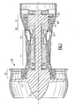
- FIG 2 shows a turbine blade 24 as known.
- a platform 42 is provided at a radially inner portion of the blade 24, while an airfoil 40 extends radially (as seen from the centerline 12) outwardly from the platform 42.
- flow channels 62, 68 and 70 that extend upwardly from the platform 42 and into the airfoil 40. These channels can be seen to cross over or overlap as shown at 64.
- the paths may have crossover connections 200, and may combine together to result in serpentine flow paths. It is somewhat difficult to form these internal passages.
- Figure 3A shows the prior art core injection process, where the parting line for two halves 600 of a metal die used to form the ceramic core runs from a leading edge 602 to a trailing edge 604. The two halves of the die are pulled normal to the pressure and suction sides of the ceramic core.
- a turbine blade 80 embodying the invention has a supply 82 supplying a plurality of relatively straight central channels 84, 86, 88, 90, 92, 94 and 96.
- a first turbine blade 80 embodying the invention has a pressure wall 85 and a suction wall 87.
- the central channels 84, 86, 88, 90, 92, 94 and 96 have crossover holes 98 on both the suction and pressure walls.
- the crossover holes supply cooling air to a plurality of impingement core channels 100 on the pressure wall and a plurality of impingement core channels 102 on the suction wall.
- Skin cooling holes 97 are formed in the suction and pressure walls such that air can pass through the skin cooling holes 97 from the core channels 100 and 102.
- impingement cooling occurs on both walls, and is better adapted to adequately cool the entirety of the turbine blade.
- the suction and pressure walls are adequately cooled by the channels 100 and 102.
- the crossover holes themselves provide a good deal of cooling.
- Figure 5 does not show leading edge 105 or trailing edge 107 cooling, it should be understood that additional cooling schemes could be provided at those locations.
- the flow from the crossover holes 98 across to the opposed walls is generally unimpeded.
- the impingement cooling effect is quite efficient.
- the crossover holes are smaller as measured between edges 105 and 107 than are central channels 84, 86, 88, 90, 92, 94, 96, 100 and 102.
- the impingement channels shown in Figure 5 can be injected as an integral part of the feed cavities, as shown in Figure 6A , or individual cores assembled onto the feed cavity, as shown in Figure 6B .
- the cores may be formed of appropriate metals or ceramic.
- Figure 6A shows how the impingement skin cores 100 and 102 can be injected as an integral part of the feed cavity 84.
- the parting line for the two halves of a core die runs from leading edge to trailing edge, as shown in Figure 3a .
- the parting line for the two halves 610 of the core die runs from pressure side to suction side.
- the two halves of the die are pulled normal to the leading 612 and trailing 614 edges of the ceramic core.
- Several of these cores are made in this manner and assembled in the wax die to create the cooling passages.
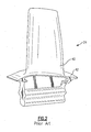
- Figure 6B shows how the impingement skin cores are assembled onto the feed cavity to form the core assembly in Figure 7 that is used in forming the Figure 5 embodiment.
- side pieces 112 and 114 are attached to the central core 110.
- Plugs 118 form the crossover holes and are received in holes 300 in central core 110.
- the skin cooling openings 97 shown in Figure 5 can be drilled or formed by pins 116. Several of these cores are made in this manner and assembled in the wax die to create the cooling passages.
- Figure 8 shows another embodiment 200, wherein a single central core channel supplies plural channels 214 on the suction wall 204 and plural core channels 216 on the pressure walls 202. There are central channels 206, 208 and 210 supplying sets of core channels 214 and 216. As shown, at least one of the central channels 210 actually feeds three core channels 216/214. Crossover holes 212 are provided as in the first embodiment.
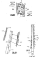
- Figure 9 shows the core structure 250 for forming the Figure 8 embodiment.
- plural side pieces 252, 254, 256 and 258 are attached to the central core 250.
- Plugs 260 form the crossover holes and are received in holes 300 in central core 250.
- the skin cooling openings 97 can be drilled or formed by pins similar to pins 116 ( Figure 7 ).
- Figure 10 shows an alternate embodiment of the invention where the impingement passages are divided into segments called boxcars 700.
- the cores to form such a version may have ribs to provide separation. This feature is known from leading edge impingement channels.
- the present invention in its preferred embodiments described above thus provides an impingement cooling arrangement wherein cooling air is directed along the length of the airfoil and directed through crossover holes to impingement core channels adjacent the suction and pressure walls.
- the impingement air provides a good deal of cooling effect at those walls.
- the components are illustrated as a turbine blade, the invention does have application as a vane or even a blade outer air seal, for example.
- the size of the crossover holes can be designed to ensure there is little radial flow in the impingement channels, or alternatively to provide for some radial flow. Also, various optional features such as trip strips, dimples, turbulators, or other heat transfer enhancing features may be used.
Abstract
Description
- This application relates to a gas turbine engine component wherein a plurality of cooling channels extend radially outwardly through an airfoil, and have crossover holes to supply impingement cooling air to both the suction and pressure walls of the airfoil.
- Gas turbine engines are known, and typically include plural sections. Often a fan delivers to a compressor section. Air is compressed in a compressor section and delivered downstream to a combustor section. The compressed air is mixed with fuel and combusted in a combustor section. Products of combustion then pass downstream over turbine rotors. The turbine rotors typically receive a plurality of removable blades. The products of combustion are quite hot, and the turbine blades are subjected to high temperatures. In addition, stationary vanes are positioned adjacent to the rotor blades.
- To cool the blades and vanes, cooling schemes have been developed. Air may be circulated within various cooling channels in an airfoil that defines part of the blade or vane. In many known airfoils, the cooling air flows along radial paths. Alternatively, the cooling air may flow through serpentine paths within the blade to cool the blade. With either of these schemes, cooling is more efficient near a root of the airfoil, before the air is unduly heated. Also, such paths may need to taper, as air is bled off through film cooling holes. This also results in less cooling near a tip of the airfoil.
- Impingement cooling air channels have been provided adjacent a trailing edge or a leading edge of the blade. In this type channel, cooling air is received from a core and directed against an outer wall of the blade. Impingement cooling channels have generally not been used along the sides of the airfoils.
- Recently, a type of cooling channel known as a "micro-circuit" has been developed. A "micro-circuit" is a very thin cooling channel formed adjacent a suction or pressure wall of the turbine blade. These channels receive cooling air from radial flow channels and perform some cooling on the suction or pressure wall. Typically, air passes through a tortuous path over pedestals.
- Impingement channels are simpler to manufacture than microcircuits or serpentine paths. Even so, impingement cooling has not been relied upon as essentially the exclusive mode of cooling an airfoil in the prior art.
- In disclosed embodiments of this invention, cooling air is circulated through a plurality of central channels along an airfoil for a gas turbine engine component. As disclosed, the engine component is a turbine blade, however, this invention extends to vanes or other gas turbine engine components.
- The cooling air passes along the central channels, and the central channels are provided with crossover holes providing the cooling air to impingement core channels adjacent both a suction and pressure wall. The cooling air passes through the crossover holes, and passes outwardly and against an opposed wall of the impingement core channel. The flow from the crossover hole to the wall is generally unimpeded, and provides impingement cooling at the wall.
- In addition, film cooling holes are formed in an outer skin of the wall. The air passes through these film cooling holes to further cool an outer surface of the pressure and suction walls.
- The present invention provides very efficient cooling, essentially all from impingement cooling. In addition, in disclosed embodiments,the relatively straight flow paths of the central channels and the impingement core channels are simpler to form than the prior art paths.
- In one embodiment, each of the central channels feeds at least two sets of impingement core channels on the suction and pressure walls.
- These and other features of the present invention can be best understood from the following specification and drawings, the following of which is a brief description.
-
-
Figure 1 schematically shows a gas turbine engine. -
Figure 2 schematically shows a turbine blade. -
Figure 3 is a cross-sectional view through a portion of a prior art turbine blade. -
Figure 3A shows the prior art core injection process. -
Figure 4 is a cross-sectional view through an inventive turbine blade. -
Figure 5 is a cross-sectional view of one turbine blade according to this invention. -
Figure 6A schematically shows the core die for forming cores in theFigure 5 turbine blade. -
Figure 6B schematically shows the core assembly process -
Figure 7 shows an assembled core used in formation of the turbine blade. -
Figure 8 is a cross-sectional view of a second embodiment. -
Figure 9 shows a core assembly process for forming the second embodiment. -
Figure 10 shows another embodiment. - A
gas turbine engine 10, such as a turbofan gas turbine engine, circumferentially disposed about an engine centerline, oraxial centerline axis 12 is shown inFigure 1 . Theengine 10 includes afan 14,compressors combustion section 18 andturbines compressors combustion section 18 and expanded inturbines turbines rotors 22 which rotate in response to the expansion, driving thecompressors fan 14. The turbines comprise alternating rows of rotating airfoils orblades 24 and static airfoils orvanes 26. In fact, this view is quite schematic, andblades 24 andvanes 26 are actually removable. It should be understood that this view is included simply to provide a basic understanding of the sections in a gas turbine engine, and not to limit the invention. This invention extends to all types of gas turbine engines for all types of applications. In fact, the invention can extend to other type turbines, such as steam turbines. -
Figure 2 shows aturbine blade 24 as known. As known, aplatform 42 is provided at a radially inner portion of theblade 24, while anairfoil 40 extends radially (as seen from the centerline 12) outwardly from theplatform 42. As mentioned above, it is typical to provide cooling air within theairfoil 40. Thus, as shown inFigure 3 , in the priorart turbine blade 24 there areflow channels 62, 68 and 70 that extend upwardly from theplatform 42 and into theairfoil 40. These channels can be seen to cross over or overlap as shown at 64. The paths may havecrossover connections 200, and may combine together to result in serpentine flow paths. It is somewhat difficult to form these internal passages. -
Figure 3A shows the prior art core injection process, where the parting line for twohalves 600 of a metal die used to form the ceramic core runs from aleading edge 602 to a trailingedge 604. The two halves of the die are pulled normal to the pressure and suction sides of the ceramic core. - As shown in
Figure 4 , aturbine blade 80 embodying the invention has asupply 82 supplying a plurality of relatively straightcentral channels - As shown in
Figure 5 , afirst turbine blade 80 embodying the invention has apressure wall 85 and asuction wall 87. Thecentral channels crossover holes 98 on both the suction and pressure walls. The crossover holes supply cooling air to a plurality ofimpingement core channels 100 on the pressure wall and a plurality ofimpingement core channels 102 on the suction wall. Skin cooling holes 97 are formed in the suction and pressure walls such that air can pass through the skin cooling holes 97 from thecore channels - With the preferred inventive arrangement, impingement cooling occurs on both walls, and is better adapted to adequately cool the entirety of the turbine blade. In particular, the suction and pressure walls are adequately cooled by the
channels - While the
Figure 5 embodiment does not showleading edge 105 or trailingedge 107 cooling, it should be understood that additional cooling schemes could be provided at those locations. In general, and as can be appreciated fromFigure 5 , the flow from the crossover holes 98 across to the opposed walls is generally unimpeded. Thus, the impingement cooling effect is quite efficient. Also, it can be seen that the crossover holes are smaller as measured betweenedges central channels - The impingement channels shown in
Figure 5 can be injected as an integral part of the feed cavities, as shown inFigure 6A , or individual cores assembled onto the feed cavity, as shown inFigure 6B . The cores may be formed of appropriate metals or ceramic. -
Figure 6A shows how theimpingement skin cores feed cavity 84. Instead of the parting line for the two halves of a core die running from leading edge to trailing edge, as shown inFigure 3a , the parting line for the twohalves 610 of the core die runs from pressure side to suction side. The two halves of the die are pulled normal to the leading 612 and trailing 614 edges of the ceramic core. Several of these cores are made in this manner and assembled in the wax die to create the cooling passages. -
Figure 6B shows how the impingement skin cores are assembled onto the feed cavity to form the core assembly inFigure 7 that is used in forming theFigure 5 embodiment. Here,side pieces central core 110.Plugs 118 form the crossover holes and are received inholes 300 incentral core 110. Theskin cooling openings 97 shown inFigure 5 can be drilled or formed bypins 116. Several of these cores are made in this manner and assembled in the wax die to create the cooling passages. -
Figure 8 shows anotherembodiment 200, wherein a single central core channel suppliesplural channels 214 on thesuction wall 204 andplural core channels 216 on thepressure walls 202. There arecentral channels core channels central channels 210 actually feeds threecore channels 216/214. Crossover holes 212 are provided as in the first embodiment. -
Figure 9 shows thecore structure 250 for forming theFigure 8 embodiment. Here,plural side pieces central core 250.Plugs 260 form the crossover holes and are received inholes 300 incentral core 250. Although not shown, theskin cooling openings 97 can be drilled or formed by pins similar to pins 116 (Figure 7 ). -
Figure 10 shows an alternate embodiment of the invention where the impingement passages are divided into segments calledboxcars 700. The cores to form such a version may have ribs to provide separation. This feature is known from leading edge impingement channels. - The present invention in its preferred embodiments described above thus provides an impingement cooling arrangement wherein cooling air is directed along the length of the airfoil and directed through crossover holes to impingement core channels adjacent the suction and pressure walls. The impingement air provides a good deal of cooling effect at those walls.
- Although the components are illustrated as a turbine blade, the invention does have application as a vane or even a blade outer air seal, for example.
- The size of the crossover holes can be designed to ensure there is little radial flow in the impingement channels, or alternatively to provide for some radial flow. Also, various optional features such as trip strips, dimples, turbulators, or other heat transfer enhancing features may be used.
- Although a preferred embodiment of this invention has been disclosed, a worker of ordinary skill in this art would recognize that certain modifications would come within the scope of this invention. For that reason, the following claims should be studied to determine the true scope and content of this invention.
Claims (11)
- A gas turbine engine component (24) comprising:a platform (42) and an airfoil (40) extending outwardly of the platform (42), the airfoil (40) having a suction wall (87) and a pressure wall (85);a plurality of central channels (84...94; 206...210) received within said airfoil (40) and extending from said platform (42) outwardly toward a tip of said airfoil (40); andsaid central channels (84...94; 206...210) each being provided with plural crossover holes (98; 212) for directing cooling air to at least one core channel (100, 102; 214, 216) associated with each of the pressure and suction walls (85, 87), and a supply (82) to supply air to the central channels (84...94; 206...210), through said crossover holes (98; 212), and against a wall of said core channels (100, 102; 214, 216).
- The gas turbine engine component as set forth in Claim 1, wherein skin cooling holes (97) are formed in said pressure and suction walls (85, 87), such that the air can pass through the skin cooling holes from said core channels (100, 102; 214, 216).
- The gas turbine engine component as set forth in Claim 1 or 2, wherein said crossover holes (98; 212) extend for a lesser dimension than do either said central channel (84...94; 206...210) or said core channel (100, 102; 214, 216) measured along a distance from a leading edge of said airfoil (40) towards a trailing edge.
- The gas turbine engine component as set forth in any preceding Claim, wherein the gas turbine engine component is a turbine blade (24).
- A turbine blade (24) comprising:a platform (42) and an airfoil (40) extending outwardly of the platform (42), the airfoil (40) having a suction wall (87) and a pressure wall (85);a plurality of central channels (84...94; 206...210) received within said airfoil (40) and extending from said platform (42) outwardly toward a tip of said airfoil (40);said central channels (84...94; 206...210) each being provided with plural crossover holes (98; 212) for directing cooling air to at least one core channel (100, 102; 214, 216) associated with each of said pressure and suction walls (85, 87), and a supply (82) to supply air received within the central channels (84...94; 206...210) through said crossover holes (98; 212), and against a wall of said core channels (100, 102; 214, 216);skin cooling holes (97) formed in said pressure and suction walls (85, 87), such that the air can leave the skin cooling holes (97); andsaid crossover holes (98; 212) extending for a lesser dimension than do either said central channel (84...94; 206...210) or said core channel (100, 102; 214, 216) measured along a distance from a leading edge of said airfoil (40) towards a trailing edge.
- The turbine blade as set forth in any preceding Claim, wherein at least one of said central channels (206, 208, 210) supplies cooling air to at least a plurality of core channels (214, 216) on at least one of said suction and pressure walls (85, 87).
- The turbine blade as set forth in Claim 6, wherein said at least one of said central channels (206, 208, 210) supplies cooling air through crossover holes (212) to plural core channels (214, 216) on both of said pressure and suction walls (89, 87).
- The turbine blade as set forth in Claim 7, wherein said at least one of said central channels (210) supplies cooling air to at least three core channels (214, 216) on each of said suction and pressure walls (85, 87).
- The turbine blade as set forth in any preceding Claim, where pressure side and suction side impingement channels (100, 102; 214, 216) are divided into separate boxcars (700).
- A gas turbine engine component (24) comprising:a platform (42) and an airfoil (40) extending outwardly of the platform (42), the airfoil (40) having a suction wall (87) and a pressure wall (85);a plurality of central channels (84...94; 206...210) received within said airfoil (40) and extending from said platform (42) outwardly toward a tip of said airfoil (40); andsaid central channels (84...94; 206, 210) each being provided with plural crossover holes (98; 212) for directing cooling air to at least one core channel (100, 102; 214, 216) associated with at least one of the pressure and suction walls (85, 87), and a supply (82) to supply air to the central channels (84...94; 206...210), through said crossover holes (98; 212), and against a wall of said core channels (100, 102; 214, 216).
- A gas turbine engine component (24) comprising:a body;a plurality of central channels (84...94; 206, 210) received with said body; andsaid central channels (84...94; 206, 210) each being provided with plural crossover holes (98; 212) for directing cooling air to at least one core channel (100, 102; 214, 216) associated with walls (85, 87) of said body, and a supply (82) to supply air to the central channels (84...94; 206, 210) through the crossover holes (98; 212) and against one of said walls (85, 87).
Applications Claiming Priority (1)
| Application Number | Priority Date | Filing Date | Title |
|---|---|---|---|
| US11/707,702 US7837441B2 (en) | 2007-02-16 | 2007-02-16 | Impingement skin core cooling for gas turbine engine blade |
Publications (3)
| Publication Number | Publication Date |
|---|---|
| EP1959097A2 true EP1959097A2 (en) | 2008-08-20 |
| EP1959097A3 EP1959097A3 (en) | 2014-04-16 |
| EP1959097B1 EP1959097B1 (en) | 2015-12-02 |
Family
ID=39512611
Family Applications (1)
| Application Number | Title | Priority Date | Filing Date |
|---|---|---|---|
| EP08250544.7A Active EP1959097B1 (en) | 2007-02-16 | 2008-02-15 | Impingement skin core cooling for gas turbine engine blade |
Country Status (2)
| Country | Link |
|---|---|
| US (1) | US7837441B2 (en) |
| EP (1) | EP1959097B1 (en) |
Families Citing this family (20)
| Publication number | Priority date | Publication date | Assignee | Title |
|---|---|---|---|---|
| US9039370B2 (en) | 2012-03-29 | 2015-05-26 | Solar Turbines Incorporated | Turbine nozzle |
| US9115590B2 (en) | 2012-09-26 | 2015-08-25 | United Technologies Corporation | Gas turbine engine airfoil cooling circuit |
| US9739171B2 (en) | 2012-11-16 | 2017-08-22 | United Technologies Corporation | Turbine engine cooling system with an open loop circuit |
| WO2015065659A1 (en) * | 2013-10-31 | 2015-05-07 | United Technologies Corporation | Gas turbine engine airfoil with auxiliary flow channel |
| US9803500B2 (en) * | 2014-05-05 | 2017-10-31 | United Technologies Corporation | Gas turbine engine airfoil cooling passage configuration |
| US10323524B2 (en) | 2015-05-08 | 2019-06-18 | United Technologies Corporation | Axial skin core cooling passage for a turbine engine component |
| US10502066B2 (en) | 2015-05-08 | 2019-12-10 | United Technologies Corporation | Turbine engine component including an axially aligned skin core passage interrupted by a pedestal |
| US10428659B2 (en) | 2015-12-21 | 2019-10-01 | United Technologies Corporation | Crossover hole configuration for a flowpath component in a gas turbine engine |
| US10731472B2 (en) | 2016-05-10 | 2020-08-04 | General Electric Company | Airfoil with cooling circuit |
| US10415396B2 (en) | 2016-05-10 | 2019-09-17 | General Electric Company | Airfoil having cooling circuit |
| US10526898B2 (en) * | 2017-10-24 | 2020-01-07 | United Technologies Corporation | Airfoil cooling circuit |
| US10907479B2 (en) | 2018-05-07 | 2021-02-02 | Raytheon Technologies Corporation | Airfoil having improved leading edge cooling scheme and damage resistance |
| US10941663B2 (en) | 2018-05-07 | 2021-03-09 | Raytheon Technologies Corporation | Airfoil having improved leading edge cooling scheme and damage resistance |
| JP7213103B2 (en) * | 2019-02-26 | 2023-01-26 | 三菱重工業株式会社 | wings and machines equipped with them |
| US11759850B2 (en) | 2019-05-22 | 2023-09-19 | Siemens Energy Global GmbH & Co. KG | Manufacturing aligned cooling features in a core for casting |
| US11220916B2 (en) | 2020-01-22 | 2022-01-11 | General Electric Company | Turbine rotor blade with platform with non-linear cooling passages by additive manufacture |
| US11248471B2 (en) | 2020-01-22 | 2022-02-15 | General Electric Company | Turbine rotor blade with angel wing with coolant transfer passage between adjacent wheel space portions by additive manufacture |
| US11492908B2 (en) | 2020-01-22 | 2022-11-08 | General Electric Company | Turbine rotor blade root with hollow mount with lattice support structure by additive manufacture |
| US11242760B2 (en) | 2020-01-22 | 2022-02-08 | General Electric Company | Turbine rotor blade with integral impingement sleeve by additive manufacture |
| US11846203B1 (en) | 2023-01-17 | 2023-12-19 | Honeywell International Inc. | Turbine nozzle with dust tolerant impingement cooling |
Citations (4)
| Publication number | Priority date | Publication date | Assignee | Title |
|---|---|---|---|---|
| US5383766A (en) * | 1990-07-09 | 1995-01-24 | United Technologies Corporation | Cooled vane |
| US5667359A (en) * | 1988-08-24 | 1997-09-16 | United Technologies Corp. | Clearance control for the turbine of a gas turbine engine |
| EP1091091A2 (en) * | 1999-10-05 | 2001-04-11 | United Technologies Corporation | Method and apparatus for cooling a wall within a gas turbine engine |
| EP1953343A2 (en) * | 2007-01-24 | 2008-08-06 | United Technologies Corporation | Cooling system for a gas turbine blade and corresponding gas turbine blade |
Family Cites Families (20)
| Publication number | Priority date | Publication date | Assignee | Title |
|---|---|---|---|---|
| US3191908A (en) * | 1961-05-02 | 1965-06-29 | Rolls Royce | Blades for fluid flow machines |
| US3806276A (en) * | 1972-08-30 | 1974-04-23 | Gen Motors Corp | Cooled turbine blade |
| US4179240A (en) * | 1977-08-29 | 1979-12-18 | Westinghouse Electric Corp. | Cooled turbine blade |
| US4542867A (en) * | 1983-01-31 | 1985-09-24 | United Technologies Corporation | Internally cooled hollow airfoil |
| US5720431A (en) * | 1988-08-24 | 1998-02-24 | United Technologies Corporation | Cooled blades for a gas turbine engine |
| US5356265A (en) * | 1992-08-25 | 1994-10-18 | General Electric Company | Chordally bifurcated turbine blade |
| US5702232A (en) * | 1994-12-13 | 1997-12-30 | United Technologies Corporation | Cooled airfoils for a gas turbine engine |
| US5813836A (en) * | 1996-12-24 | 1998-09-29 | General Electric Company | Turbine blade |
| US5931638A (en) * | 1997-08-07 | 1999-08-03 | United Technologies Corporation | Turbomachinery airfoil with optimized heat transfer |
| JP4976614B2 (en) * | 1997-10-27 | 2012-07-18 | シーメンス エナジー インコーポレイテッド | Superalloy casting method |
| US5976337A (en) * | 1997-10-27 | 1999-11-02 | Allison Engine Company | Method for electrophoretic deposition of brazing material |
| US6402470B1 (en) * | 1999-10-05 | 2002-06-11 | United Technologies Corporation | Method and apparatus for cooling a wall within a gas turbine engine |
| US6280140B1 (en) * | 1999-11-18 | 2001-08-28 | United Technologies Corporation | Method and apparatus for cooling an airfoil |
| GB0114503D0 (en) * | 2001-06-14 | 2001-08-08 | Rolls Royce Plc | Air cooled aerofoil |
| US6981846B2 (en) * | 2003-03-12 | 2006-01-03 | Florida Turbine Technologies, Inc. | Vortex cooling of turbine blades |
| US7097425B2 (en) * | 2003-08-08 | 2006-08-29 | United Technologies Corporation | Microcircuit cooling for a turbine airfoil |
| US6896487B2 (en) * | 2003-08-08 | 2005-05-24 | United Technologies Corporation | Microcircuit airfoil mainbody |
| US6890154B2 (en) * | 2003-08-08 | 2005-05-10 | United Technologies Corporation | Microcircuit cooling for a turbine blade |
| US7488156B2 (en) * | 2006-06-06 | 2009-02-10 | Siemens Energy, Inc. | Turbine airfoil with floating wall mechanism and multi-metering diffusion technique |
| US7625180B1 (en) * | 2006-11-16 | 2009-12-01 | Florida Turbine Technologies, Inc. | Turbine blade with near-wall multi-metering and diffusion cooling circuit |
-
2007
- 2007-02-16 US US11/707,702 patent/US7837441B2/en not_active Expired - Fee Related
-
2008
- 2008-02-15 EP EP08250544.7A patent/EP1959097B1/en active Active
Patent Citations (4)
| Publication number | Priority date | Publication date | Assignee | Title |
|---|---|---|---|---|
| US5667359A (en) * | 1988-08-24 | 1997-09-16 | United Technologies Corp. | Clearance control for the turbine of a gas turbine engine |
| US5383766A (en) * | 1990-07-09 | 1995-01-24 | United Technologies Corporation | Cooled vane |
| EP1091091A2 (en) * | 1999-10-05 | 2001-04-11 | United Technologies Corporation | Method and apparatus for cooling a wall within a gas turbine engine |
| EP1953343A2 (en) * | 2007-01-24 | 2008-08-06 | United Technologies Corporation | Cooling system for a gas turbine blade and corresponding gas turbine blade |
Also Published As
| Publication number | Publication date |
|---|---|
| US7837441B2 (en) | 2010-11-23 |
| EP1959097A3 (en) | 2014-04-16 |
| US20080273963A1 (en) | 2008-11-06 |
| EP1959097B1 (en) | 2015-12-02 |
Similar Documents
| Publication | Publication Date | Title |
|---|---|---|
| EP1959097B1 (en) | Impingement skin core cooling for gas turbine engine blade | |
| EP1918522B1 (en) | Component for a gas turbine engine | |
| US7775768B2 (en) | Turbine component with axially spaced radially flowing microcircuit cooling channels | |
| US8172533B2 (en) | Turbine blade internal cooling configuration | |
| EP2290193B1 (en) | Turbine vane | |
| US9206697B2 (en) | Aerofoil cooling | |
| US6290463B1 (en) | Slotted impingement cooling of airfoil leading edge | |
| JP6661702B2 (en) | Airfoil with tip rail cooling | |
| EP1288437A2 (en) | Turbine airfoil for gas turbine engine | |
| US10066488B2 (en) | Turbomachine blade with generally radial cooling conduit to wheel space | |
| EP2917494B1 (en) | Blade for a turbomachine | |
| JP2017534791A5 (en) | ||
| US10837291B2 (en) | Turbine engine with component having a cooled tip | |
| EP3273005A1 (en) | An air cooled component for a gas turbine engine | |
| US8157525B2 (en) | Methods and apparatus relating to turbine airfoil cooling apertures | |
| US10655485B2 (en) | Stress-relieving pocket in turbine nozzle with airfoil rib | |
| EP2867479B1 (en) | Component for a gas turbine engine and corresponding gas turbine engine | |
| US20210131291A1 (en) | Turbine blade with tip shroud cooling passage | |
| CN110249112B (en) | Turbine engine component with insert | |
| US20130236329A1 (en) | Rotor blade with one or more side wall cooling circuits | |
| EP3677750B1 (en) | Gas turbine engine component with a trailing edge discharge slot | |
| EP2378071A1 (en) | Turbine assembly having cooling arrangement and method of cooling |
Legal Events
| Date | Code | Title | Description |
|---|---|---|---|
| PUAI | Public reference made under article 153(3) epc to a published international application that has entered the european phase |
Free format text: ORIGINAL CODE: 0009012 |
|
| AK | Designated contracting states |
Kind code of ref document: A2 Designated state(s): AT BE BG CH CY CZ DE DK EE ES FI FR GB GR HR HU IE IS IT LI LT LU LV MC MT NL NO PL PT RO SE SI SK TR |
|
| AX | Request for extension of the european patent |
Extension state: AL BA MK RS |
|
| PUAL | Search report despatched |
Free format text: ORIGINAL CODE: 0009013 |
|
| AK | Designated contracting states |
Kind code of ref document: A3 Designated state(s): AT BE BG CH CY CZ DE DK EE ES FI FR GB GR HR HU IE IS IT LI LT LU LV MC MT NL NO PL PT RO SE SI SK TR |
|
| AX | Request for extension of the european patent |
Extension state: AL BA MK RS |
|
| RIC1 | Information provided on ipc code assigned before grant |
Ipc: F01D 5/18 20060101AFI20140307BHEP |
|
| 17P | Request for examination filed |
Effective date: 20141016 |
|
| RBV | Designated contracting states (corrected) |
Designated state(s): AT BE BG CH CY CZ DE DK EE ES FI FR GB GR HR HU IE IS IT LI LT LU LV MC MT NL NO PL PT RO SE SI SK TR |
|
| AKX | Designation fees paid |
Designated state(s): DE GB |
|
| AXX | Extension fees paid |
Extension state: AL Extension state: RS Extension state: MK Extension state: BA |
|
| GRAP | Despatch of communication of intention to grant a patent |
Free format text: ORIGINAL CODE: EPIDOSNIGR1 |
|
| INTG | Intention to grant announced |
Effective date: 20150701 |
|
| GRAS | Grant fee paid |
Free format text: ORIGINAL CODE: EPIDOSNIGR3 |
|
| GRAA | (expected) grant |
Free format text: ORIGINAL CODE: 0009210 |
|
| AK | Designated contracting states |
Kind code of ref document: B1 Designated state(s): DE GB |
|
| REG | Reference to a national code |
Ref country code: GB Ref legal event code: FG4D |
|
| REG | Reference to a national code |
Ref country code: DE Ref legal event code: R096 Ref document number: 602008041376 Country of ref document: DE |
|
| REG | Reference to a national code |
Ref country code: DE Ref legal event code: R097 Ref document number: 602008041376 Country of ref document: DE |
|
| PLBE | No opposition filed within time limit |
Free format text: ORIGINAL CODE: 0009261 |
|
| STAA | Information on the status of an ep patent application or granted ep patent |
Free format text: STATUS: NO OPPOSITION FILED WITHIN TIME LIMIT |
|
| RAP2 | Party data changed (patent owner data changed or rights of a patent transferred) |
Owner name: UNITED TECHNOLOGIES CORPORATION |
|
| 26N | No opposition filed |
Effective date: 20160905 |
|
| REG | Reference to a national code |
Ref country code: DE Ref legal event code: R082 Ref document number: 602008041376 Country of ref document: DE Representative=s name: SCHMITT-NILSON SCHRAUD WAIBEL WOHLFROM PATENTA, DE |
|
| REG | Reference to a national code |
Ref country code: DE Ref legal event code: R082 Ref document number: 602008041376 Country of ref document: DE Representative=s name: SCHMITT-NILSON SCHRAUD WAIBEL WOHLFROM PATENTA, DE Ref country code: DE Ref legal event code: R081 Ref document number: 602008041376 Country of ref document: DE Owner name: UNITED TECHNOLOGIES CORP. (N.D.GES.D. STAATES , US Free format text: FORMER OWNER: UNITED TECHNOLOGIES CORP., HARTFORD, CONN., US |
|
| REG | Reference to a national code |
Ref country code: DE Ref legal event code: R081 Ref document number: 602008041376 Country of ref document: DE Owner name: RAYTHEON TECHNOLOGIES CORPORATION (N.D.GES.D.S, US Free format text: FORMER OWNER: UNITED TECHNOLOGIES CORP. (N.D.GES.D. STAATES DELAWARE), FARMINGTON, CONN., US |
|
| PGFP | Annual fee paid to national office [announced via postgrant information from national office to epo] |
Ref country code: GB Payment date: 20230121 Year of fee payment: 16 Ref country code: DE Payment date: 20230119 Year of fee payment: 16 |
|
| P01 | Opt-out of the competence of the unified patent court (upc) registered |
Effective date: 20230519 |