EP1958869A1 - Boat propulsion unit - Google Patents
Boat propulsion unit Download PDFInfo
- Publication number
- EP1958869A1 EP1958869A1 EP08002868A EP08002868A EP1958869A1 EP 1958869 A1 EP1958869 A1 EP 1958869A1 EP 08002868 A EP08002868 A EP 08002868A EP 08002868 A EP08002868 A EP 08002868A EP 1958869 A1 EP1958869 A1 EP 1958869A1
- Authority
- EP
- European Patent Office
- Prior art keywords
- shift
- boat
- rotational speed
- control means
- speed
- Prior art date
- Legal status (The legal status is an assumption and is not a legal conclusion. Google has not performed a legal analysis and makes no representation as to the accuracy of the status listed.)
- Granted
Links
Images





Classifications
-
- B—PERFORMING OPERATIONS; TRANSPORTING
- B63—SHIPS OR OTHER WATERBORNE VESSELS; RELATED EQUIPMENT
- B63H—MARINE PROPULSION OR STEERING
- B63H21/00—Use of propulsion power plant or units on vessels
- B63H21/21—Control means for engine or transmission, specially adapted for use on marine vessels
- B63H21/213—Levers or the like for controlling the engine or the transmission, e.g. single hand control levers
Definitions
- the present invention relates to a boat propulsion unit, a method for controlling same, and a boat in which shift switching between forward, neutral and reverse is electrically made by remote control.
- Patent Document 1 One conventional boat of this type is disclosed in Patent Document 1.
- a shift device comprising: a remote control operation device having a remote control shift lever for remotely making shifting between forward, neutral and reverse; a boat propulsion unit having a shift switching device for shift switching between forward, neutral and reverse, and a shift actuator for driving the shift switching device; and a control means for controlling the operation of the shift actuator based on the displacement of the remote control shift lever when the remote control shift lever is operated within a prescribed shift range from a neutral position; wherein the control means controls the operation amount of the actuator with respect to a unit displacement of the remote control shift lever such that it is different in different sections of the shift range.”
- Patent Document 1 JP-A-2005-297785
- an object of the present invention to provide a boat propulsion unit and a method for controlling same capable of preventing shocks on gears in meshing engagement with each other and an abrupt behavior thereof even when the remote control shift lever is quickly tilted to the reverse side from a cruising mode.
- a boat propulsion unit comprising: a shift switching device for shift switching between forward, neutral and reverse according to an operation signal from a remote control means; a shift actuator for driving the shift switching device; an engine for rotating a propeller; and a control means which receives an operation signal from the remote control means and controls operation of the shift actuator, wherein, when the control means receives the operation signal from the remote control means and the operation signal is a signal commanding a shift operation from the neutral position to the forward position or to the reverse position, the control means is configured to drive the shift actuator to make shift switching from the neutral position to the forward position or to the reverse position only when at least one of the engine rotational speed, the boat speed and the propeller shaft rotational speed is equal to or lower than a respective prescribed value therefor.
- control means is configured to drive the shift actuator to make shift switching from the neutral position to the forward position or to the reverse position only when both the engine rotational speed and the boat speed or the propeller shaft rotational speed are equal to or lower than respective prescribed values therefor.
- control means receives an operation signal from the remote control means and the operation signal is a signal commanding a shift operation from the forward position through the neutral position to the reverse position
- the control means is configured to drive the shift actuator to make shift switching from the neutral position to the reverse position only when at least one of the engine rotational speed, the boat speed and the propeller shaft rotational speed is equal to or lower than a respective prescribed value therefor.
- control means is configured to not drive the shift actuator when the throttle opening is equal to or greater than a prescribed value, even when at least one of the engine rotational speed, the boat speed and the propeller shaft rotational speed is equal to or lower than a respective prescribed value therefor, and is configured to drive the shift actuator to make shift switching from the neutral position to the forward position or to the reverse position only when the throttle opening becomes smaller than the prescribed value therefor.
- the boat propulsion unit further comprises a failure detection means for detecting a failed state of a sensor for detecting the engine rotational speed, and/or the boat speed and/or the propeller shaft rotational speed, wherein, when a failure is detected, the shift actuator is driven according to the operative position of the remote control shift lever to accomplish normal shift switch driving by means of the shift switching device even when a shift operation from the neutral position to the forward position or to the reverse position is detected.
- control means when the control means receives the operation signal from the remote control means and the operation signal is a signal commanding a shift operation from the neutral position to the forward position or to the reverse position, the control means is configured to drive the shift actuator to make shift switching from the neutral position to the forward position or to the reverse position only when the engine rotational speed is equal to or lower than a prescribed value, and wherein this prescribed value of the engine rotational speed is set based on the boat speed, such that a value of this prescribed value at a higher boat speed is greater than a value of this prescribed value at a lower boat speed.
- the boat speed is estimated and calculated from the intake pressure to the engine and the engine rotational speed.
- the boat propulsion unit further comprises a throttle valve and a throttle actuator for opening and closing the throttle valve; a throttle control device for controlling operation of the throttle actuator; and a shift detection means for detecting completion of shift switching, wherein the throttle control device is configured to control the throttle actuator not to operate until the shift switching is completed.
- a boat having a plurality of boat propulsion units, wherein at least one of the plurality of boat propulsion units is a boat propulsion unit according to one of the above embodiments.
- a method for controlling a boat propulsion unit wherein, when a remote control means is rotated from a neutral position toward a reverse position or towards a forward position and the remote control means reaches a threshold between the neutral position and the reverse position or forward position, and if a boat speed and/or an engine rotational speed and/or a throttle opening at this time are greater than respective prescribed values, a switch control means stops driving of a shift actuator for a time period to maintain the state of the neutral position, and, then, when the boat speed, and/or the engine rotational speed, and/or the throttle opening reach the prescribed values, respectively, the shift actuator is driven by the switch control means to accomplish shift switching from the neutral position to the reverse position or to the forward position.
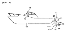
- FIG. 1 to FIG. 9 show a first embodiment of the present teaching.
- a boat of this embodiment has an outboard motor 11 as a "boat propulsion unit" attached to the stem of its hull 10.
- the outboard motor 11 is controlled to steer the boat by means of a remote control operation device 12, a key switch device 13, a steering wheel device 14 and so on arranged in the cockpit on the hull 10.
- the remote control operation device 12 has a remote control body 16 in which a remote control side ECU 17 is housed, and a remote control shift lever 18 for throttle and shift operation. Shift switching between forward, neutral and reverse is remotely made by means of the remote control shift lever 18.
- the center position, at which the remote control shift lever 18 stands vertically, is the neutral position (N)
- the position at which the remote control shift lever 18 is tilted forward by a prescribed angle from the center position and the position at which the remote control shift lever 18 is tilted backward by a prescribed angle from the center position are the forward position (F) and the reverse position(R), respectively.
- the operation information including the speed at which the remote control shift lever 18 is operated and the angle through which the remote control shift lever 18 is operated is detected by a potentiometer 19 as a "lever position sensor” and transmitted to the remote control side ECU 17. In other words, the position of the remote control shift lever 18 is detected by the potentiometer 19.
- a signal from the remote control side ECU 17 is transmitted to an engine side ECU 21 of the outboard motor 11 as shown in FIG. 6 .
- the engine side ECU 21 controls the drive of the shift motor 25 of a shift actuator 22 based on the displacement of the remote control shift lever 18, and a shift switching device 23 is actuated by the shift actuator 22 to make shift switching between forward, neutral and reverse.
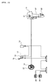
- the key switch device 13 is connected to the remote control side ECU 17 of the remote control operation device 12 as shown in FIG. 2 .
- the key switch device 13 has a starter switch and a main/stop switch, although not shown.
- the steering wheel device 14 is provided therein with a steering wheel side ECU (not shown) and has a steering wheel 27 for steering the boat.
- the steering wheel position is detected by a position sensor, which is connected to the steering wheel side ECU via a signal circuit.
- the steering wheel side ECU of the steering wheel device 14 is connected to the engine side ECU 21 of the remote control operation device 12 via a DBWCAN cable as a signal line.
- DBW stands for Drive-By-Wire, which is a control device that uses electrical connection instead of mechanical connection
- CAN stands for "Controller Area Network.”
- Designated as 28 in FIG. 2 is a gauge.
- the engine 30 is located in an upper part of the outboard motor 11 as shown in FIG. 1 etc., and the output of the engine 30 is transmitted via a drive shaft 31 and a shift device 32 to a propeller shaft 34 to which a propeller 33 is fixed.
- Shift switching between forward, neutral and reverse in the shift device 32 is made by the shift switching device 23, and the shift switching device 23 is driven by the shift actuator 22.
- the outboard motor 11 has a propeller shaft 34 extending generally horizontally in a casing 37 and a propeller 33 attached to the propeller shaft 34 as shown in FIG. 1 to FIG. 3 .
- the propeller shaft 34 is connected to the driveshaft 31 via a gear mechanism 38 for switching between forward and reverse modes, that is, for shift switching.
- the gear mechanism 38 has a forward gear 39 and a reverse gear 40 rotatably mounted on the propeller shaft 34.
- the gears 39 and 40 are both meshing engagement with a pinion 41 fixed to the driveshaft 31, which is driven to rotate clockwise as viewed from above, so as to rotate in opposite directions.
- the forward gear 39 and reverse gear 40 are located on the rear side and front side, respectively, with respect to the forward direction of the boat (left in FIG. 3 ).
- a sleeve-shaped dog clutch 42 is splined on the propeller shaft 34 between the gears 39 and 40, and the dog clutch 42 is slidable in the axial direction of the propeller shaft 34.
- the dog clutch 42 has claws 42a extending radially.
- the gears 39 and 40 have claws 39a and 40a, respectively, facing the claws 42a.
- the claws form a claw clutch.
- the propeller shaft 34 has an insertion hole 34a formed in its front end along the axial direction thereof and opening at its front end, and a shift sleeve 44 is received in the insertion hole 34a for sliding movement in the axial direction.
- a slot 34b elongated in the axial direction is formed through the peripheral wall of the insertion hole 34a of the propeller shaft 34.
- the shift sleeve 44 and the dog clutch 42 have through-holes 44b and 42b, respectively, extending in the diameter direction thereof, and a pin 46 is inserted in the through-hole 42b of the dog clutch 42, the slot 34b of the propeller shaft 34, and the through-hole 44b of the shift sleeve 44.
- the shift sleeve 44 has detent balls 48 retractably protruding from the outer peripheral surface of the shift sleeve 44 and removably engageable with recesses 34c of the propeller shaft 34.
- the detent balls 48 are urged in the protruding direction by a spring 49 and a pressing member 50.
- the shift sleeve 44 has a front end 44a to which a shifter 51 slidable to the right and left as viewed in FIG. 3 is connected, and the shifter 51 has an engaging groove 51 a extending vertically.
- a drive pin 54a located in a position offset in a crank fashion with respect to the axis of rotation of the shift shaft 54 is received in the engaging groove 51 a.
- the shifter 51 slides to slide the dog clutch 42.
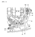
- the shift shaft 54 extends vertically, and, as shown in a plan view of FIG. 4 , has an upper end 54b to which a lever 55 is secured.
- One end of a lever shift rod 56 is rotatably connected to the distal end of the lever 55, and the other end of the lever shift rod 56 is rotatably connected to a slider 58 slidably mounted on a shift rail 57.
- the slider 58 is slid in a prescribed direction by the shift actuator 22, the shift shaft 54 is rotated in a prescribed direction via the lever shift rod 56 and the lever 55.
- the shift actuator 22 has a shift motor 25 that is a DC motor as a driving source, a reduction mechanism (not shown) and so on, and is configured to drive the slider 58 in a prescribed direction.
- the shift actuator 22 has a shift position sensor (SPS) 61 for detecting the shift position (forward position, neutral position or reverse position) and the shift speed.
- SPS shift position sensor
- a signal from the shift position sensor 61 is inputted into a control microcomputer 64 as a "control means" of the engine side ECU 21.
- An engine rotational speed sensor for example, crankshaft sensor or camshaft sensor
- a boat speed sensor for example, water pressure sensor or paddle wheel type sensor
- a propeller shaft rotational speed sensor 77 for detecting the rotational speed of the propeller shaft 34 are provided.
- An engine rotational speed signal, a boat speed signal, and a propeller shaft rotational speed signal from the sensors 67, 68 and 77 are inputted into the control microcomputer 64.
- control microcomputer 64 controls the operation of the shift actuator 22 based on the displacement of the remote control shift lever 18.
- control microcomputer 64 has a shift detection means 70 for detecting whether a shift operation from the forward position through the neutral position to the reverse position was made based on a signal from the potentiometer 19 for detecting the position of the remote control shift lever 18, and a switch control means 71 for stopping or starting shift switch driving.
- the switch control means 71 does not drive the shift actuator 22 when the shift detection means 70 detects a shift operation from the forward position through the neutral position to the reverse position and the value of the engine rotational speed detected by the engine rotational speed sensor 67 is higher than a prescribed value, and drives the shift actuator 22 and controls the shift switching device 23 to start shift switch driving to the reverse position when the engine rotational speed decreases to a value equal to or smaller than the prescribed value.
- the switch control means 71 does not drives the shift actuator 22 when the throttle opening is equal to or greater than a certain value even when the engine rotational speed is lower than the prescribed value, and drives the shift actuator 22 and controls the shift switching device 23 to start the shift switch driving when the throttle opening decreases to a value equal to or smaller than the certain value.
- a failure detection means 73 for detecting a failed state of the engine rotational speed sensor 67 is provided, and a failure detection signal from the failure detection means 73 is inputted into the switch control means 71.
- the failure detection means 73 determines whether or not the engine rotational speed sensor 67 is failed by detecting an abnormal signal from the engine rotational speed sensor 67.
- the switch control means 71 drives the shift actuator 22 according to the operative position of the remote control shift lever 18 so that normal shift switch driving by means of the shift switching device 23 can be made even when the shift detection means 70 detects a shift operation of the remote control shift lever 18 from the forward position through the neutral position to the reverse position and the engine rotational speed is higher than a prescribed value (the value is not accurate because of the failure).
- a minimum shift driving operation can be carried out even when the engine rotational speed sensor 67 is failed and the engine rotational speed is detected as not having decreased to a value lower than the prescribe value although the engine rotational speed has decreased to a value lower than the prescribe value in reality, a normal shift driving operation can be carried out.
- the boat speed may be estimated or calculated from the intake pressure to the engine 30 and the engine rotational speed.
- the boat speed can be estimated even when the boat speed sensor 68 is not connected or the boat speed sensor 68 is failed.
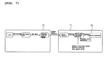
- the operation information including the speed at which the remote control shift lever 18 is operated and the angle through which the remote control shift lever 18 is operated is detected by the potentiometer 19 and transmitted to the engine side ECU 21 via the remote control side ECU 17 to detect the position of the remote control shift lever 18.
- the lever position voltage is inputted into an interface (I/F) and converted therein into lever position data, and a target value is calculated based on the lever position data (LPS data).
- the target value is then converted into a target shift position signal, which is in turn inputted into the control microcomputer 64 of the engine side ECU 21 and subjected to shift control.
- a request from the shift control is subjected to shift driving determination by the switch control means 71, and a prescribed current is inputted into the shift actuator 22, whereby the shift motor 25 of the shift actuator 22 is driven in a prescribed direction at a prescribed speed.
- the current shift position of the shift actuator 22 is detected by the shift position sensor 61 and provided to the shift control as a feedback, and a feedback control is performed to shift it to a desired position.
- the dog clutch 42 When the shift motor 25 of the shift actuator 22 is driven, the dog clutch 42 is slid in a prescribed direction via the slider 58, the lever shift rod 56, the shift shaft 54, the shifter 51, the shift sleeve 44, the pin 46 and so on. Then, either of the claws 42a of the dog clutch 42 is brought into engagement with the claw 39a of the forward gear 39 or the claw 40a of the reverse gear 40 to accomplish shift-in switching.
- step S10 it is determined whether or not the engine rotational speed sensor 67 is failed in step S10. If the engine rotational speed sensor 67 is failed, the control is terminated without performing the shift control of the present invention. If the engine rotational speed sensor 67 is not failed, the process goes to step S11.
- step S11 a signal from the potentiometer 19 is inputted into the shift detection means 70, and it is determined by the shift detection means 70 whether the shift operation of the remote control shift lever 18 from the forward position through the neutral position to the reverse position was made. If not, the process returns to step S10. If it is determined so, the process goes to step S12.
- step S12 a signal of the value of the engine rotational speed detected by the engine rotational speed sensor 67 is inputted into the switch control means 71, and it is determined whether or not the engine rotational speed is lower than a prescribed value (1500 rpm, for example). If it is determined that the engine rotational speed is higher than the prescribed value ("NO"), the process returns to step S10 and the switch control means 71 does not drive the shift actuator 22 even when a shift operation of the remote control shift lever 18 from the forward position through the neutral position to the reverse position was made.
- a prescribed value (1500 rpm, for example
- step S12 Since no actual shift switch driving from the neutral position to the reverse position is made, the shift position is maintained in the neutral position state and the engine rotational speed decreases. After that, when the engine rotational speed becomes equal to or lower than a prescribed value, it is determined that the engine rotational speed is lower than a prescribed value in step S12, and the process goes to step S13.
- step S10 when the engine rotational speed is lower than the prescribed value, the process may not return to step S10 but goes to step S13 from step S12.
- step S13 a signal of the throttle opening from a throttle opening sensor (not shown) is inputted into the switch control means 71, and it is determined whether or not the throttle opening is equal to or larger than a certain value. If “YES,” the process returns to step S10, and shift driving is not performed immediately. If “NO,” the process goes to step S14.
- step S14 the switch control means 71 drives the shift actuator 22, and shift switch driving to the reverse position (R) by the shift switching device 23 is started.
- the shift actuator 22 is not driven when the throttle opening is equal to or larger than a certain value, and the shift actuator 22 is driven to start shift switch driving by the shift switching device 23 when the throttle opening becomes equal to or smaller than the certain value.
- the engine rotational speed of the engine 30 may rapidly increase after shift switching if the throttle is open. With the above configuration, however, a shift-in in such a case can be avoided and damage of the reverse gear 40 etc. and an abrupt behavior of the boat can be prevented.
- While the shift actuator 22 is driven only if the engine rotational speed is equal to or lower than a prescribed value when the remote control shift lever 18 is shifted from the neutral position to the reverse position in this first embodiment, the present invention is limited thereto.
- the shift actuator 22 may be driven when the boat speed is equal to or lower than a prescribed value or when the propeller shaft rotational speed is equal to or lower than a prescribed value.
- a signal from the boat speed sensor 68 or the propeller shaft rotational speed sensor is inputted into the control microcomputer 64 and the switch control means 71 performs the control.
- the shift actuator 22 is not driven to prevent a shock being applied between the reverse gear 40, the pinion 41 and the dog clutch 42 as in the first embodiment. As a result, damage of the reverse gear 40 etc. and an abrupt behavior of the boat can be prevented.
- the switch control means 71 drives the shift actuator 22 according to the operative position of the remote control shift lever 18 so that normal shift switch driving by means of the shift switching device 23 can be made even when the shift detection means 70 detects a shift operation of the remote control shift lever 18 from the forward position through the neutral position to the reverse position and when the boat speed or the propeller shaft rotational speed is higher than a prescribed value (the value is not accurate because of the failure).
- the shift actuator 22 may be driven when the engine rotational speed, and the boat speed or the propeller shaft rotational speed are equal to or lower than respective prescribed values.
- a throttle valve (not shown) and a throttle actuator 75 for opening and closing the throttle valve are provided, and a throttle control device 76 for controlling the operation of the throttle actuator 75 is provided as shown in FIG. 6 .
- the throttle control device 76 may control the throttle actuator 75 not to operate until a signal from the shift detection means 70 for detecting completion of shift switching is inputted into the throttle control device 76 and shift switching is completed.
- the shift actuator 22 is driven by the switch control means 71 to accomplish shift switching from the neutral position (N) to the reverse position (F) (shift-in).
- the second embodiment is different from the first embodiment in the method of controlling the switch control means 71.
- the switch control means 71 does not drive the shift actuator 22 when the shift detection means 70 detects a shift switching from the neutral position to the forward position or reverse position and the engine rotational speed detected by the engine rotational speed sensor 67 is equal to or higher than a prescribed value, and drives the shift actuator 22 and controls the shift switching device 23 to start shift switch driving to the reverse position when the engine rotational speed decreases to a value equal to or smaller than the prescribed value as in the first embodiment.
- the prescribed value of the engine rotational speed is changed based on the boat speed detected by the boat speed sensor 68.
- the prescribed value is increased to a value larger than that which is used when the boat speed is high.
- the present teaching is not limited thereto. It is needless to say that boat inboard-outboard motor or the like may be used as the "boat propulsion unit.” Also, while shift control is performed when shift operation from the forward position through neutral position to the reverse position is made, the present teaching is not limited thereto. The present teaching is applicable to shift operation from the neutral position to the forward position. When a quick shift-in is made when the remote control shift lever 18 is in the neutral position and the engine rotational speed is high, a shock is generated. Therefore, the present teaching is also effective in such a case.
- a boat propulsion unit comprising: a shift switching device for shift switching between forward, neutral and reverse according to an operation signal from a remote control means; a shift actuator for driving the shift switching device; an engine for rotating a propeller; and a control means which receives an operation signal from the remote control means and controls operation of the shift actuator, wherein when the control means receives the operation signal from the remote control means and the operation signal is a signal commanding a shift operation from the neutral position to the forward position or reverse position, the control means drives the shift actuator to make shift switching from the neutral position to the forward position or reverse position when at least one of the engine rotational speed, boat speed and propeller shaft rotational speed is equal to or lower than a prescribed value therefor.
- control means drives the shift actuator to make shift switching from the neutral position to the forward position or reverse position when both the engine rotational speed and the boat speed or the propeller shaft rotational speed are equal to or lower than respective prescribed values.
- control means drives the shift actuator to make shift switching from the neutral position to the forward position or reverse position when at least one of the engine rotational speed, boat speed and propeller shaft rotational speed is equal to or lower than a prescribed value therefor.
- control means does not drive the shift actuator when the throttle opening is equal to or greater than a prescribed value even when at least one of the engine rotational speed, the boat speed and the propeller shaft rotational speed is equal to or lower than a prescribed value therefor, and drives the shift actuator to make shift switching from the neutral position to the forward position or reverse position when the throttle opening becomes smaller than the prescribed value.
- it may comprise a failure detection means for detecting a failed state of a sensor for detecting the engine rotational speed, the boat speed or the propeller shaft rotational speed, and a feature that when a failure is detected, the shift actuator is driven according to the operative position of the remote control shift lever to accomplish normal shift switch driving by means of the shift switching device even when a shift operation from the neutral position to the forward position or reverse position is detected.
- a boat propulsion unit comprising: a shift switching device for shift switching between forward, neutral and reverse according to an operation signal from a remote control means; a shift actuator for driving the shift switching device; an engine for rotating a propeller; and a control means which receives an operation signal from the remote control means and controls operation of the shift actuator, wherein when the control means receives the operation signal from the remote control means and the operation signal is a signal commanding a shift operation from the neutral position to the forward position or reverse position, the control means drives the shift actuator to make shift switching from the neutral position to the forward position or reverse position when the engine rotational speed is equal to or lower than a prescribed value, and in that the prescribed value of the engine rotational speed can be changed depending on the boat speed and is controlled to a value greater than that which is used when the boat speed is high when the boat speed is low.
- the boat speed is estimated and calculated from the intake pressure to the engine and the engine rotational speed.
- the description further discloses an embodiment comprising a throttle valve and a throttle actuator for opening and closing the throttle valve; a throttle control device for controlling operation of the throttle actuator; and a shift detection means for detecting completion of shift switching, and a feature that the throttle control device controls the throttle actuator not to operate until the shift switching is completed.
- a boat provided with a boat propulsion unit according to any of the above embodiments, and a boat having a plurality of boat propulsion units, wherein at least one of the plurality of boat propulsion units is a boat propulsion unit according to any of the above embodiments.
- a boat propulsion unit comprising: a shift switching device for shift switching between forward, neutral and reverse according to an operation signal from a remote control means; a shift actuator for driving the shift switching device; an engine for rotating a propeller; and a control means which receives an operation signal from the remote control means and controls operation of the shift actuator, wherein when the control means receives the operation signal from the remote control means and the operation signal is a signal commanding a shift operation from the neutral position to the forward position or reverse position, the control means drives the shift actuator to make shift switching from the neutral position to the forward position or reverse position when at least one of the engine rotational speed, boat speed and propeller shaft rotational speed is equal to or lower than a prescribed value therefor.
- control means drives the shift actuator to make shift switching from the neutral position to the forward position or reverse position when both the engine rotational speed and the boat speed or the propeller shaft rotational speed are equal to or lower than respective prescribed values.
- control means when the control means receives an operation signal from the remote control means and the operation signal is a signal commanding a shift operation from the forward position through the neutral position to the reverse position, the control means drives the shift actuator to make shift switching from the neutral position to the reverse position when at least one of the engine rotational speed, boat speed and propeller shaft rotational speed is equal to or lower than a prescribed value therefor.
- control means does not drive the shift actuator when the throttle opening is equal to or greater than a prescribed value even when at least one of the engine rotational speed, the boat speed and the propeller shaft rotational speed is equal to or lower than a prescribed value therefor, and drives the shift actuator to make shift switching from the neutral position to the forward position or reverse position when the throttle opening becomes smaller than the prescribed value.
- the boat propulsion unit may further comprise a failure detection means for detecting a failed state of a sensor for detecting the engine rotational speed, the boat speed or the propeller shaft rotational speed, wherein when a failure is detected, the shift actuator is driven according to the operative position of the remote control shift lever to accomplish normal shift switch driving by means of the shift switching device even when a shift operation from the neutral position to the forward position or reverse position is detected.
- a boat propulsion unit comprising: a shift switching device for shift switching between forward, neutral and reverse according to an operation signal from a remote control means; a shift actuator for driving the shift switching device; an engine for rotating a propeller; and a control means which receives an operation signal from the remote control means and controls operation of the shift actuator, wherein when the control means receives the operation signal from the remote control means and the operation signal is a signal commanding a shift operation from the neutral position to the forward position or reverse position, the control means drives the shift actuator to make shift switching from the neutral position to the forward position or reverse position when the engine rotational speed is equal to or lower than a prescribed value, and in that the prescribed value of the engine rotational speed can be changed depending on the boat speed and is controlled to a value greater than that which is used when the boat speed is high when the boat speed is low.
- the boat speed is estimated and calculated from the intake pressure to the engine and the engine rotational speed.
- the boat propulsion unit may further comprise a throttle valve and a throttle actuator for opening and closing the throttle valve; a throttle control device for controlling operation of the throttle actuator; and a shift detection means for detecting completion of shift switching, wherein the throttle control device controls the throttle actuator not to operate until the shift switching is completed.
- a boat provided with a boat propulsion unit according to any one of the above embodiments.
- a boat having a plurality of boat propulsion units, wherein at least one of the plurality of boat propulsion units is a boat propulsion unit according to any one of the above embodiments.
- the control means when the control means receives the operation signal from the remote control means and the operation signal is a signal commanding a shift operation from the neutral position to the forward position or reverse position, the control means drives the shift actuator to make shift switching from the neutral position to the forward position or reverse position when at least one of the engine rotational speed, boat speed and propeller shaft rotational speed is equal to or lower than a prescribed value therefor. Therefore, a shift-in at a time when the engine rotational speed, the boat speed or the propeller shaft rotational speed is higher than a prescribed value therefor can be avoided, and shocks on gears meshing engagement with each other and an abrupt behavior of the boat can be prevented.
- the shift actuator is driven to make shift switching from the neutral position to the forward position or reverse position when both the engine rotational speed and the boat speed or the propeller shaft rotational speed are equal to or lower than respective prescribed values. Therefore, appropriate control can be accomplished as compared to the case where control is performed based on whether one of the engine rotational speed, the boat speed or the propeller shaft rotational speed is higher than a prescribed value therefor.
- the control means when the control means receives an operation signal from the remote control means and the operation signal is a signal commanding a shift operation from the forward position through the neutral position to the reverse position, the control means drives the shift actuator to make shift switching from the neutral position to the forward position or reverse position when at least one of the engine rotational speed, boat speed and propeller shaft rotational speed is equal to or lower than a prescribed value therefor.
- the control means does not drive the shift actuator when the throttle opening is equal to or greater than a prescribed value even when at least one of the engine rotational speed, the boat speed and the propeller shaft rotational speed is equal to or lower than a prescribed value therefor, and drives the shift actuator to make shift switching from the neutral position to the forward position or reverse position when the throttle opening becomes smaller than the prescribed value.
- the engine rotational speed of the engine may rapidly increase after shift switching if the throttle is open.
- a failure detection means for detecting a failed state of a sensor for detecting the engine rotational speed, and the boat speed or the propeller shaft rotational speed is provided, and, when a failure is detected, the shift actuator is driven according to the operative position of the remote control shift lever to accomplish normal shift switch driving by means of the shift switching device even when a shift operation from the neutral position to the forward position or reverse position is detected. Therefore, even if the sensor for detecting the engine rotational speed etc. is failed and cannot measure the engine rotational speed etc., a minimum shift driving operation can be carried out. For example, even when the sensor is failed and the engine rotational speed is detected as not having decreased to a value lower than the prescribe value although the engine rotational speed has decreased to a value lower than the prescribe value in reality, a normal shift driving operation can be carried out.
- the prescribed value of the engine rotational speed can be changed depending on the boat speed and is controlled to a value greater than that which is used when the boat speed is high when the boat speed is low. Therefore, since the prescribed value of the engine rotational speed is increased to a larger value when the boat speed is low, frequent shift-in or shift-out for adjustment of the boat position required to put the boat ashore can be accomplished reliably.
- the boat speed is estimated and calculated from the intake pressure to the engine and the engine rotational speed. Therefore, the boat speed can be estimated and the operation described in Claim 1 or 6 can be carried out even when the boat speed sensor is not connected or the boat speed sensor is failed.
- a throttle actuator for opening and closing the throttle valve; a throttle control device for controlling operation of the throttle actuator; and a shift detection means for detecting completion of shift switching are provided, and the throttle control device controls the throttle actuator not to operate until the shift switching is completed. Therefore, a quick increase in the engine rotational speed during shift switching can be prevented, and a shift-in in a high engine rotational speed condition can be avoided. As a result, damage of a reverse gear etc. and a rapid behavior of the boat can be prevented.
- a boat provided with a boat propulsion unit having above effects.
- a boat provided with a plurality of boat propulsion units each having above effects.
- an embodiment including: a control microcomputer 64 for controlling the operation of a shift actuator 22 based on the displacement of a remote control shift lever for remotely switching between forward, neutral and reverse is provided, wherein the control microcomputer 64 has a shift detection means 70 for detecting whether a shift operation from the neutral position to the forward position or reverse position was made based on a signal from a lever position sensor for detecting the position of the remote control shift lever 18; and a switch control means 71 which does not drive a shift motor 25 when a shift operation from the neutral position to the forward position or reverse position is detected by the shift detection means 70 and the engine rotational speed detected by the engine rotational speed sensor 67 is higher than a prescribed value, and drives the shift motor 25 and controls the shift switching device to start shift switch driving when engine rotational speed decreases to a value equal
Landscapes
- Chemical & Material Sciences (AREA)
- Engineering & Computer Science (AREA)
- Combustion & Propulsion (AREA)
- Mechanical Engineering (AREA)
- Ocean & Marine Engineering (AREA)
- Control Of Vehicle Engines Or Engines For Specific Uses (AREA)
- Combined Controls Of Internal Combustion Engines (AREA)
- Control Of Transmission Device (AREA)
- Revetment (AREA)
Abstract
Description
- The present invention relates to a boat propulsion unit, a method for controlling same, and a boat in which shift switching between forward, neutral and reverse is electrically made by remote control.
- One conventional boat of this type is disclosed in Patent Document 1.
- That is, it is described in Patent Document 1 that "a shift device comprising: a remote control operation device having a remote control shift lever for remotely making shifting between forward, neutral and reverse; a boat propulsion unit having a shift switching device for shift switching between forward, neutral and reverse, and a shift actuator for driving the shift switching device; and a control means for controlling the operation of the shift actuator based on the displacement of the remote control shift lever when the remote control shift lever is operated within a prescribed shift range from a neutral position; wherein the control means controls the operation amount of the actuator with respect to a unit displacement of the remote control shift lever such that it is different in different sections of the shift range."
Patent Document 1:JP-A-2005-297785 - However, in such a conventional device, when the remote control shift lever is quickly tilted to the reverse side from an advancing mode to make a shift-in in the opposite direction, since the shift-in to the reverse side is made before the engine rotational speed and the boat speed are sufficiently reduced. Then, a shock at that time may be exerted on gears in meshing engagement with each other and the boat may have an abrupt behavior.
- That is, when the remote control shift lever is quickly tilted to the reverse side from a forward mode to make a shift-in in the opposite direction, since a force urges the propeller to rotate in the opposite direction while the propeller is still rotating in the forward direction and inertia force in the direction is generated, a large force is generated between gears on the propeller side and gears on the engine side. Then, a shock at that time may be exerted on the gears, and the boat may have an abrupt behavior.
- It is, therefore, an object of the present invention to provide a boat propulsion unit and a method for controlling same capable of preventing shocks on gears in meshing engagement with each other and an abrupt behavior thereof even when the remote control shift lever is quickly tilted to the reverse side from a cruising mode.
- This objective is solved in an inventive manner by a boat propulsion unit, comprising: a shift switching device for shift switching between forward, neutral and reverse according to an operation signal from a remote control means; a shift actuator for driving the shift switching device; an engine for rotating a propeller; and a control means which receives an operation signal from the remote control means and controls operation of the shift actuator, wherein, when the control means receives the operation signal from the remote control means and the operation signal is a signal commanding a shift operation from the neutral position to the forward position or to the reverse position, the control means is configured to drive the shift actuator to make shift switching from the neutral position to the forward position or to the reverse position only when at least one of the engine rotational speed, the boat speed and the propeller shaft rotational speed is equal to or lower than a respective prescribed value therefor.
- Preferably, the control means is configured to drive the shift actuator to make shift switching from the neutral position to the forward position or to the reverse position only when both the engine rotational speed and the boat speed or the propeller shaft rotational speed are equal to or lower than respective prescribed values therefor.
- Further, preferably when the control means receives an operation signal from the remote control means and the operation signal is a signal commanding a shift operation from the forward position through the neutral position to the reverse position, the control means is configured to drive the shift actuator to make shift switching from the neutral position to the reverse position only when at least one of the engine rotational speed, the boat speed and the propeller shaft rotational speed is equal to or lower than a respective prescribed value therefor.
- Still further, preferably the control means is configured to not drive the shift actuator when the throttle opening is equal to or greater than a prescribed value, even when at least one of the engine rotational speed, the boat speed and the propeller shaft rotational speed is equal to or lower than a respective prescribed value therefor, and is configured to drive the shift actuator to make shift switching from the neutral position to the forward position or to the reverse position only when the throttle opening becomes smaller than the prescribed value therefor.
- According to a preferred embodiment, the boat propulsion unit further comprises a failure detection means for detecting a failed state of a sensor for detecting the engine rotational speed, and/or the boat speed and/or the propeller shaft rotational speed, wherein, when a failure is detected, the shift actuator is driven according to the operative position of the remote control shift lever to accomplish normal shift switch driving by means of the shift switching device even when a shift operation from the neutral position to the forward position or to the reverse position is detected.
- Preferably, when the control means receives the operation signal from the remote control means and the operation signal is a signal commanding a shift operation from the neutral position to the forward position or to the reverse position, the control means is configured to drive the shift actuator to make shift switching from the neutral position to the forward position or to the reverse position only when the engine rotational speed is equal to or lower than a prescribed value, and wherein this prescribed value of the engine rotational speed is set based on the boat speed, such that a value of this prescribed value at a higher boat speed is greater than a value of this prescribed value at a lower boat speed.
- Further, preferably the boat speed is estimated and calculated from the intake pressure to the engine and the engine rotational speed.
- According to another preferred embodiment, the boat propulsion unit further comprises a throttle valve and a throttle actuator for opening and closing the throttle valve; a throttle control device for controlling operation of the throttle actuator; and a shift detection means for detecting completion of shift switching, wherein the throttle control device is configured to control the throttle actuator not to operate until the shift switching is completed.
- There might also be provided a boat with a boat propulsion unit according to the above teaching.
- Further, preferably there might be provided a boat having a plurality of boat propulsion units, wherein at least one of the plurality of boat propulsion units is a boat propulsion unit according to one of the above embodiments.
- This objective is further solved by a method for controlling a boat propulsion unit, wherein, when a remote control means is rotated from a neutral position toward a reverse position or towards a forward position and the remote control means reaches a threshold between the neutral position and the reverse position or forward position, and if a boat speed and/or an engine rotational speed and/or a throttle opening at this time are greater than respective prescribed values, a switch control means stops driving of a shift actuator for a time period to maintain the state of the neutral position, and, then, when the boat speed, and/or the engine rotational speed, and/or the throttle opening reach the prescribed values, respectively, the shift actuator is driven by the switch control means to accomplish shift switching from the neutral position to the reverse position or to the forward position.
- In the following, the present invention is explained in greater detail with respect to several embodiments thereof in conjunction with the accompanying drawings, wherein:
- FIG. 1
- is a side view of a boat according to a first embodiment of the present teaching,
- FIG.2
- is a block diagram illustrating the connection state of a remote control operation device, an outboard motor and so on of the boat according to the first embodiment,
- FIG. 3
- is a cross-sectional view of a shift device of the boat according to the first embodiment,
- FIG. 4
- is a plan view illustrating a shift actuator and so on of the boat according to the first embodiment,
- FIG. 5
- is a side view illustrating a remote control shift lever of the boat according to the first embodiment,
- FIG. 6
- is a block diagram illustrating a remote control side ECU, an engine side ECU and so on of the boat according to the first embodiment,
- FIG.7
- is a view illustrating a control flow of the boat according to the first embodiment,
- FIG. 8
- is a flowchart of the boat according to the first embodiment, and
- FIG. 9
- is a graph chart illustrating a function of the boat according to the first embodiment.
-
- 10
- hull
- 11
- outboard motor (boat propulsion unit)
- 12
- remote control operation device
- 13
- key switch device
- 14
- steering wheel device
- 17
- remote control side ECU
- 18
- remote control shift lever
- 19
- potentiometer (lever position sensor)
- 21
- engine side ECU
- 22
- shift actuator
- 23
- shift switching device
- 25
- shift motor
- 30
- engine
- 31
- driveshaft
- 32
- shift device
- 34
- propeller shaft
- 39
- forward gear
- 40
- reverse gear
- 42
- dog clutch
- 44
- shift sleeve
- 54
- shift shaft
- 61
- shift position sensor
- 64
- control microcomputer (control means)
- 67
- engine rotational speed sensor (boat state detection means)
- 68
- boat speed sensor (boat state detection means)
- 70
- shift detection means
- 71
- switch control means
- 73
- failure detection means
- Description is hereinafter made of embodiments of the present teaching.
-
FIG. 1 to FIG. 9 show a first embodiment of the present teaching. - The constitution is first described. As shown in
FIG. 1 andFIG. 2 , a boat of this embodiment has anoutboard motor 11 as a "boat propulsion unit" attached to the stem of itshull 10. Theoutboard motor 11 is controlled to steer the boat by means of a remotecontrol operation device 12, akey switch device 13, asteering wheel device 14 and so on arranged in the cockpit on thehull 10. - The remote
control operation device 12 has aremote control body 16 in which a remotecontrol side ECU 17 is housed, and a remotecontrol shift lever 18 for throttle and shift operation. Shift switching between forward, neutral and reverse is remotely made by means of the remotecontrol shift lever 18. As shown inFIG. 5 , the center position, at which the remotecontrol shift lever 18 stands vertically, is the neutral position (N), and the position at which the remotecontrol shift lever 18 is tilted forward by a prescribed angle from the center position and the position at which the remotecontrol shift lever 18 is tilted backward by a prescribed angle from the center position are the forward position (F) and the reverse position(R), respectively. The operation information including the speed at which the remotecontrol shift lever 18 is operated and the angle through which the remotecontrol shift lever 18 is operated is detected by apotentiometer 19 as a "lever position sensor" and transmitted to the remotecontrol side ECU 17. In other words, the position of the remotecontrol shift lever 18 is detected by thepotentiometer 19. - A signal from the remote
control side ECU 17 is transmitted to anengine side ECU 21 of theoutboard motor 11 as shown inFIG. 6 . Theengine side ECU 21 controls the drive of theshift motor 25 of ashift actuator 22 based on the displacement of the remotecontrol shift lever 18, and ashift switching device 23 is actuated by theshift actuator 22 to make shift switching between forward, neutral and reverse. - The
key switch device 13 is connected to the remotecontrol side ECU 17 of the remotecontrol operation device 12 as shown inFIG. 2 . Thekey switch device 13 has a starter switch and a main/stop switch, although not shown. - The
steering wheel device 14 is provided therein with a steering wheel side ECU (not shown) and has asteering wheel 27 for steering the boat. The steering wheel position is detected by a position sensor, which is connected to the steering wheel side ECU via a signal circuit. - The steering wheel side ECU of the
steering wheel device 14 is connected to theengine side ECU 21 of the remotecontrol operation device 12 via a DBWCAN cable as a signal line. Here, DBW stands for Drive-By-Wire, which is a control device that uses electrical connection instead of mechanical connection, and CAN stands for "Controller Area Network." - Designated as 28 in
FIG. 2 is a gauge. - The
engine 30 is located in an upper part of theoutboard motor 11 as shown inFIG. 1 etc., and the output of theengine 30 is transmitted via adrive shaft 31 and ashift device 32 to apropeller shaft 34 to which apropeller 33 is fixed. - Shift switching between forward, neutral and reverse in the
shift device 32 is made by theshift switching device 23, and theshift switching device 23 is driven by theshift actuator 22. - More specifically, the
outboard motor 11 has apropeller shaft 34 extending generally horizontally in acasing 37 and apropeller 33 attached to thepropeller shaft 34 as shown inFIG. 1 to FIG. 3 . Thepropeller shaft 34 is connected to thedriveshaft 31 via agear mechanism 38 for switching between forward and reverse modes, that is, for shift switching. - The
gear mechanism 38 has aforward gear 39 and areverse gear 40 rotatably mounted on thepropeller shaft 34. Thegears pinion 41 fixed to thedriveshaft 31, which is driven to rotate clockwise as viewed from above, so as to rotate in opposite directions. - The
forward gear 39 andreverse gear 40 are located on the rear side and front side, respectively, with respect to the forward direction of the boat (left inFIG. 3 ). - A sleeve-shaped
dog clutch 42 is splined on thepropeller shaft 34 between thegears dog clutch 42 is slidable in the axial direction of thepropeller shaft 34. - The
dog clutch 42 hasclaws 42a extending radially. Thegears claws claws 42a. The claws form a claw clutch. - The
propeller shaft 34 has aninsertion hole 34a formed in its front end along the axial direction thereof and opening at its front end, and ashift sleeve 44 is received in theinsertion hole 34a for sliding movement in the axial direction. Aslot 34b elongated in the axial direction is formed through the peripheral wall of theinsertion hole 34a of thepropeller shaft 34. - The
shift sleeve 44 and thedog clutch 42 have through-holes pin 46 is inserted in the through-hole 42b of thedog clutch 42, theslot 34b of thepropeller shaft 34, and the through-hole 44b of theshift sleeve 44. - Therefore, when the
shift sleeve 44 moves, thepin 46 is moved in the axial direction within theslot 34b, and thedog clutch 42 is moved in the axial direction of thepropeller shaft 34 via thepin 46. - The
shift sleeve 44 hasdetent balls 48 retractably protruding from the outer peripheral surface of theshift sleeve 44 and removably engageable withrecesses 34c of thepropeller shaft 34. Thedetent balls 48 are urged in the protruding direction by aspring 49 and a pressingmember 50. - In addition, the
shift sleeve 44 has afront end 44a to which ashifter 51 slidable to the right and left as viewed inFIG. 3 is connected, and theshifter 51 has an engaginggroove 51 a extending vertically. - At the lower end of a
shift shaft 54 of theshift switching device 23, adrive pin 54a located in a position offset in a crank fashion with respect to the axis of rotation of theshift shaft 54 is received in the engaginggroove 51 a. When thedrive pin 54a is rotated eccentrically by rotation of theshift shaft 54, theshifter 51 slides to slide thedog clutch 42. - When the
shift shaft 54 is rotated in one direction, thedog clutch 42 is slid in one direction. When theshift shaft 54 is rotated in the opposite direction, thedog clutch 42 is slid in the opposite direction. - The
shift shaft 54 extends vertically, and, as shown in a plan view ofFIG. 4 , has anupper end 54b to which alever 55 is secured. One end of alever shift rod 56 is rotatably connected to the distal end of thelever 55, and the other end of thelever shift rod 56 is rotatably connected to aslider 58 slidably mounted on ashift rail 57. When theslider 58 is slid in a prescribed direction by theshift actuator 22, theshift shaft 54 is rotated in a prescribed direction via thelever shift rod 56 and thelever 55. - The
shift actuator 22 has ashift motor 25 that is a DC motor as a driving source, a reduction mechanism (not shown) and so on, and is configured to drive theslider 58 in a prescribed direction. - As shown in
FIG. 6 , theshift actuator 22 has a shift position sensor (SPS) 61 for detecting the shift position (forward position, neutral position or reverse position) and the shift speed. A signal from theshift position sensor 61 is inputted into acontrol microcomputer 64 as a "control means" of theengine side ECU 21. - An engine rotational speed sensor (for example, crankshaft sensor or camshaft sensor) 67 for detecting the engine rotational speed of the
engine 30, a boat speed sensor (for example, water pressure sensor or paddle wheel type sensor) 68 for detecting the boat speed, and a propeller shaftrotational speed sensor 77 for detecting the rotational speed of thepropeller shaft 34 are provided. An engine rotational speed signal, a boat speed signal, and a propeller shaft rotational speed signal from thesensors control microcomputer 64. - When the remote
control shift lever 18 is operated within a prescribed shift range, thecontrol microcomputer 64 controls the operation of theshift actuator 22 based on the displacement of the remotecontrol shift lever 18. - More specifically, the
control microcomputer 64 has a shift detection means 70 for detecting whether a shift operation from the forward position through the neutral position to the reverse position was made based on a signal from thepotentiometer 19 for detecting the position of the remotecontrol shift lever 18, and a switch control means 71 for stopping or starting shift switch driving. - The switch control means 71 does not drive the
shift actuator 22 when the shift detection means 70 detects a shift operation from the forward position through the neutral position to the reverse position and the value of the engine rotational speed detected by the enginerotational speed sensor 67 is higher than a prescribed value, and drives theshift actuator 22 and controls theshift switching device 23 to start shift switch driving to the reverse position when the engine rotational speed decreases to a value equal to or smaller than the prescribed value. - The switch control means 71 does not drives the
shift actuator 22 when the throttle opening is equal to or greater than a certain value even when the engine rotational speed is lower than the prescribed value, and drives theshift actuator 22 and controls theshift switching device 23 to start the shift switch driving when the throttle opening decreases to a value equal to or smaller than the certain value. - In addition, a failure detection means 73 for detecting a failed state of the engine
rotational speed sensor 67 is provided, and a failure detection signal from the failure detection means 73 is inputted into the switch control means 71. The failure detection means 73 determines whether or not the enginerotational speed sensor 67 is failed by detecting an abnormal signal from the enginerotational speed sensor 67. - When a failure detection signal is inputted into the switch control means 71, the switch control means 71 drives the
shift actuator 22 according to the operative position of the remotecontrol shift lever 18 so that normal shift switch driving by means of theshift switching device 23 can be made even when the shift detection means 70 detects a shift operation of the remotecontrol shift lever 18 from the forward position through the neutral position to the reverse position and the engine rotational speed is higher than a prescribed value (the value is not accurate because of the failure). - Thus, even if the engine
rotational speed sensor 67 for detecting the engine rotational speed etc. is failed and cannot measure the engine rotational speed etc., a minimum shift driving operation can be carried out. For example, even when the enginerotational speed sensor 67 is failed and the engine rotational speed is detected as not having decreased to a value lower than the prescribe value although the engine rotational speed has decreased to a value lower than the prescribe value in reality, a normal shift driving operation can be carried out. - The boat speed may be estimated or calculated from the intake pressure to the
engine 30 and the engine rotational speed. - In this case, the boat speed can be estimated even when the
boat speed sensor 68 is not connected or theboat speed sensor 68 is failed. - The function is next described.
- When the
engine 30 is being driven with the remotecontrol shift lever 18 in the forward position and when the boat is traveling forward, the operation information including the speed at which the remotecontrol shift lever 18 is operated and the angle through which the remotecontrol shift lever 18 is operated is detected by thepotentiometer 19 and transmitted to theengine side ECU 21 via the remotecontrol side ECU 17 to detect the position of the remotecontrol shift lever 18. - When the remote
control shift lever 18 is rotated backward from the forward position through the neutral position to the reverse position in this state, the position of the remotecontrol shift lever 18 is detected by thepotentiometer 19, inputted into the remotecontrol side ECU 17 of the remotecontrol operation device 12, and converted into a lever position voltage (LPS voltage) as shown inFIG. 7 . - The lever position voltage is inputted into an interface (I/F) and converted therein into lever position data, and a target value is calculated based on the lever position data (LPS data). The target value is then converted into a target shift position signal, which is in turn inputted into the
control microcomputer 64 of theengine side ECU 21 and subjected to shift control. A request from the shift control is subjected to shift driving determination by the switch control means 71, and a prescribed current is inputted into theshift actuator 22, whereby theshift motor 25 of theshift actuator 22 is driven in a prescribed direction at a prescribed speed. - The current shift position of the
shift actuator 22 is detected by theshift position sensor 61 and provided to the shift control as a feedback, and a feedback control is performed to shift it to a desired position. - When the
shift motor 25 of theshift actuator 22 is driven, thedog clutch 42 is slid in a prescribed direction via theslider 58, thelever shift rod 56, theshift shaft 54, theshifter 51, theshift sleeve 44, thepin 46 and so on. Then, either of theclaws 42a of thedog clutch 42 is brought into engagement with theclaw 39a of theforward gear 39 or theclaw 40a of thereverse gear 40 to accomplish shift-in switching. - At the time of such shift switching, control as shown in
FIG. 8 is performed. First, it is determined whether or not the enginerotational speed sensor 67 is failed in step S10. If the enginerotational speed sensor 67 is failed, the control is terminated without performing the shift control of the present invention. If the enginerotational speed sensor 67 is not failed, the process goes to step S11. - In step S11, a signal from the
potentiometer 19 is inputted into the shift detection means 70, and it is determined by the shift detection means 70 whether the shift operation of the remotecontrol shift lever 18 from the forward position through the neutral position to the reverse position was made. If not, the process returns to step S10. If it is determined so, the process goes to step S12. - In step S12, a signal of the value of the engine rotational speed detected by the engine
rotational speed sensor 67 is inputted into the switch control means 71, and it is determined whether or not the engine rotational speed is lower than a prescribed value (1500 rpm, for example). If it is determined that the engine rotational speed is higher than the prescribed value ("NO"), the process returns to step S10 and the switch control means 71 does not drive theshift actuator 22 even when a shift operation of the remotecontrol shift lever 18 from the forward position through the neutral position to the reverse position was made. - Therefore, even when the remote
control shift lever 18 is rotated from the forward position through the neutral position to the reverse position in a high engine rotational speed state, since actual shift switch driving by theshift switching device 23 is not carried out, no shock is applied between thereverse gear 40, thepinion 41 and thedog clutch 42. As a result, damage of thereverse gear 40 etc. and a rapid behavior of the boat can be prevented. - That is, in a conventional boat propulsion unit, when the remote
control shift lever 18 is quickly tilted to the reverse side to make a shift-in into the opposite direction from a forward mode, a large impactive force is applied to the propeller and urges it to rotate in the opposite direction while the propeller is still rotating in the forward direction and inertia force in the direction is generated. In the present invention, however, since control is performed as described above, no shock is applied. Therefore, damage of thereverse gear 40 etc. and a rapid behavior of the boat can be prevented. - Since no actual shift switch driving from the neutral position to the reverse position is made, the shift position is maintained in the neutral position state and the engine rotational speed decreases. After that, when the engine rotational speed becomes equal to or lower than a prescribed value, it is determined that the engine rotational speed is lower than a prescribed value in step S12, and the process goes to step S13.
- It is matter of course that when the engine rotational speed is lower than the prescribed value, the process may not return to step S10 but goes to step S13 from step S12.
- In step S13, a signal of the throttle opening from a throttle opening sensor (not shown) is inputted into the switch control means 71, and it is determined whether or not the throttle opening is equal to or larger than a certain value. If "YES," the process returns to step S10, and shift driving is not performed immediately. If "NO," the process goes to step S14. In step S14, the switch control means 71 drives the
shift actuator 22, and shift switch driving to the reverse position (R) by theshift switching device 23 is started. - Here, even when a shift operation of the
shift actuator 22 from the neutral position to the reverse position is detected and when the engine rotational speed is equal to or lower than the prescribed value, theshift actuator 22 is not driven when the throttle opening is equal to or larger than a certain value, and theshift actuator 22 is driven to start shift switch driving by theshift switching device 23 when the throttle opening becomes equal to or smaller than the certain value. - Even when the engine rotational speed is equal to or lower than a prescribed value, the engine rotational speed of the
engine 30 may rapidly increase after shift switching if the throttle is open. With the above configuration, however, a shift-in in such a case can be avoided and damage of thereverse gear 40 etc. and an abrupt behavior of the boat can be prevented. - While the
shift actuator 22 is driven only if the engine rotational speed is equal to or lower than a prescribed value when the remotecontrol shift lever 18 is shifted from the neutral position to the reverse position in this first embodiment, the present invention is limited thereto. Theshift actuator 22 may be driven when the boat speed is equal to or lower than a prescribed value or when the propeller shaft rotational speed is equal to or lower than a prescribed value. - In this case, a signal from the
boat speed sensor 68 or the propeller shaft rotational speed sensor is inputted into thecontrol microcomputer 64 and the switch control means 71 performs the control. - When the boat speed is higher than the prescribed value, the rotational speed of the
propeller 33 is high and quick shift switching causes a large shock. Thus, in this case as well, theshift actuator 22 is not driven to prevent a shock being applied between thereverse gear 40, thepinion 41 and thedog clutch 42 as in the first embodiment. As a result, damage of thereverse gear 40 etc. and an abrupt behavior of the boat can be prevented. - In this case, when the failure detection means 73 detects a failed state of the
boat speed sensor 68 or the propeller shaftrotational speed sensor 77 and a failure detection signal is inputted into the switch control means 71, the switch control means 71 drives theshift actuator 22 according to the operative position of the remotecontrol shift lever 18 so that normal shift switch driving by means of theshift switching device 23 can be made even when the shift detection means 70 detects a shift operation of the remotecontrol shift lever 18 from the forward position through the neutral position to the reverse position and when the boat speed or the propeller shaft rotational speed is higher than a prescribed value (the value is not accurate because of the failure). - Therefore, even when the
sensor - In addition, the
shift actuator 22 may be driven when the engine rotational speed, and the boat speed or the propeller shaft rotational speed are equal to or lower than respective prescribed values. - Moreover, a throttle valve (not shown) and a
throttle actuator 75 for opening and closing the throttle valve are provided, and athrottle control device 76 for controlling the operation of thethrottle actuator 75 is provided as shown inFIG. 6 . - The
throttle control device 76 may control thethrottle actuator 75 not to operate until a signal from the shift detection means 70 for detecting completion of shift switching is inputted into thethrottle control device 76 and shift switching is completed. - In this case, a quick increase in the engine rotational speed of the
engine 30 can be prevented and a shift-in in a high engine rotational speed condition can be avoided. As a result, damage of thereverse gear 40 etc. and a rapid behavior of the boat can be prevented. - Referring now to
FIG. 9 , the relation among the motion of the remotecontrol shift lever 18, the motion of the shift, the engine rotational speed, the boat speed and the throttle opening when a quick shift operation to the reverse position is made is described. - When the remote
control shift lever 18 is rotated from the forward position (F) toward the neutral position (N) and thelever 18 reaches a threshold a between the forward position (F) and the neutral position (N), a signal from thepotentiometer 19 is transmitted to thecontrol microcomputer 64, and theshift actuator 22 is driven to accomplish shift switching from the forward position (F) to the neutral position (N) (shift out). - When the remote
control shift lever 18 is further rotated from the neutral position (N) toward the reverse position (F) and thelever 18 reaches a threshold b between the neutral position (N) and the reverse position (F), a signal from thepotentiometer 19 is transmitted to thecontrol microcomputer 64. If the boat speed A1, the engine rotational speed B1 and the throttle opening C1 at this time are greater than respective prescribed values, the switch control means 71 stops driving of theshift actuator 22 for a time period t to maintain the state of the neutral position (N). - Then, when the boat speed, the engine rotational speed, and the throttle opening reach A2, B2 and C2, respectively, which are equal to or lower than respective prescribed values, the
shift actuator 22 is driven by the switch control means 71 to accomplish shift switching from the neutral position (N) to the reverse position (F) (shift-in). - The second embodiment is different from the first embodiment in the method of controlling the switch control means 71.
- That is, the switch control means 71 does not drive the
shift actuator 22 when the shift detection means 70 detects a shift switching from the neutral position to the forward position or reverse position and the engine rotational speed detected by the enginerotational speed sensor 67 is equal to or higher than a prescribed value, and drives theshift actuator 22 and controls theshift switching device 23 to start shift switch driving to the reverse position when the engine rotational speed decreases to a value equal to or smaller than the prescribed value as in the first embodiment. - In the second embodiment, the prescribed value of the engine rotational speed is changed based on the boat speed detected by the
boat speed sensor 68. When the boat speed is low, the prescribed value is increased to a value larger than that which is used when the boat speed is high. - In this configuration, since the prescribed value of the engine rotational speed is increased to a larger value when the boat speed is low, frequent shift-in or shift-out for adjustment of the boat position required to put the boat ashore can be accomplished reliably.
- The other constitution and function are the same as those of the first embodiment and hence redundant description is omitted.
- While the
outboard motor 11 is used as a "boat propulsion unit" in the above embodiments, the present teaching is not limited thereto. It is needless to say that boat inboard-outboard motor or the like may be used as the "boat propulsion unit." Also, while shift control is performed when shift operation from the forward position through neutral position to the reverse position is made, the present teaching is not limited thereto. The present teaching is applicable to shift operation from the neutral position to the forward position. When a quick shift-in is made when the remotecontrol shift lever 18 is in the neutral position and the engine rotational speed is high, a shock is generated. Therefore, the present teaching is also effective in such a case. - The description above discloses (amongst others) for the purpose of solving the present problems, a boat propulsion unit comprising: a shift switching device for shift switching between forward, neutral and reverse according to an operation signal from a remote control means; a shift actuator for driving the shift switching device; an engine for rotating a propeller; and a control means which receives an operation signal from the remote control means and controls operation of the shift actuator, wherein when the control means receives the operation signal from the remote control means and the operation signal is a signal commanding a shift operation from the neutral position to the forward position or reverse position, the control means drives the shift actuator to make shift switching from the neutral position to the forward position or reverse position when at least one of the engine rotational speed, boat speed and propeller shaft rotational speed is equal to or lower than a prescribed value therefor.
- Preferably, the control means drives the shift actuator to make shift switching from the neutral position to the forward position or reverse position when both the engine rotational speed and the boat speed or the propeller shaft rotational speed are equal to or lower than respective prescribed values.
- Further, preferably when the control means receives an operation signal from the remote control means and the operation signal is a signal commanding a shift operation from the forward position through the neutral position to the reverse position, the control means drives the shift actuator to make shift switching from the neutral position to the forward position or reverse position when at least one of the engine rotational speed, boat speed and propeller shaft rotational speed is equal to or lower than a prescribed value therefor.
- Still further, preferably the control means does not drive the shift actuator when the throttle opening is equal to or greater than a prescribed value even when at least one of the engine rotational speed, the boat speed and the propeller shaft rotational speed is equal to or lower than a prescribed value therefor, and drives the shift actuator to make shift switching from the neutral position to the forward position or reverse position when the throttle opening becomes smaller than the prescribed value.
- Additionally, it may comprise a failure detection means for detecting a failed state of a sensor for detecting the engine rotational speed, the boat speed or the propeller shaft rotational speed, and a feature that when a failure is detected, the shift actuator is driven according to the operative position of the remote control shift lever to accomplish normal shift switch driving by means of the shift switching device even when a shift operation from the neutral position to the forward position or reverse position is detected.
- Further, there is disclosed an embodiment of a boat propulsion unit comprising: a shift switching device for shift switching between forward, neutral and reverse according to an operation signal from a remote control means; a shift actuator for driving the shift switching device; an engine for rotating a propeller; and a control means which receives an operation signal from the remote control means and controls operation of the shift actuator, wherein when the control means receives the operation signal from the remote control means and the operation signal is a signal commanding a shift operation from the neutral position to the forward position or reverse position, the control means drives the shift actuator to make shift switching from the neutral position to the forward position or reverse position when the engine rotational speed is equal to or lower than a prescribed value, and in that the prescribed value of the engine rotational speed can be changed depending on the boat speed and is controlled to a value greater than that which is used when the boat speed is high when the boat speed is low.
- Preferably, the boat speed is estimated and calculated from the intake pressure to the engine and the engine rotational speed.
- The description further discloses an embodiment comprising a throttle valve and a throttle actuator for opening and closing the throttle valve; a throttle control device for controlling operation of the throttle actuator; and a shift detection means for detecting completion of shift switching, and a feature that the throttle control device controls the throttle actuator not to operate until the shift switching is completed.
- There is further disclosed a boat provided with a boat propulsion unit according to any of the above embodiments, and a boat having a plurality of boat propulsion units, wherein at least one of the plurality of boat propulsion units is a boat propulsion unit according to any of the above embodiments.
- Thus, according to a preferred first aspect, there is disclosed a boat propulsion unit, comprising: a shift switching device for shift switching between forward, neutral and reverse according to an operation signal from a remote control means; a shift actuator for driving the shift switching device; an engine for rotating a propeller; and a control means which receives an operation signal from the remote control means and controls operation of the shift actuator, wherein when the control means receives the operation signal from the remote control means and the operation signal is a signal commanding a shift operation from the neutral position to the forward position or reverse position, the control means drives the shift actuator to make shift switching from the neutral position to the forward position or reverse position when at least one of the engine rotational speed, boat speed and propeller shaft rotational speed is equal to or lower than a prescribed value therefor.
- Further, according to a preferred second aspect, the control means drives the shift actuator to make shift switching from the neutral position to the forward position or reverse position when both the engine rotational speed and the boat speed or the propeller shaft rotational speed are equal to or lower than respective prescribed values.
- Further, according to a preferred third aspect, when the control means receives an operation signal from the remote control means and the operation signal is a signal commanding a shift operation from the forward position through the neutral position to the reverse position, the control means drives the shift actuator to make shift switching from the neutral position to the reverse position when at least one of the engine rotational speed, boat speed and propeller shaft rotational speed is equal to or lower than a prescribed value therefor.
- Further, according to a preferred fourth aspect, the control means does not drive the shift actuator when the throttle opening is equal to or greater than a prescribed value even when at least one of the engine rotational speed, the boat speed and the propeller shaft rotational speed is equal to or lower than a prescribed value therefor, and drives the shift actuator to make shift switching from the neutral position to the forward position or reverse position when the throttle opening becomes smaller than the prescribed value.
- Further, according to a preferred fifth aspect, the boat propulsion unit may further comprise a failure detection means for detecting a failed state of a sensor for detecting the engine rotational speed, the boat speed or the propeller shaft rotational speed, wherein when a failure is detected, the shift actuator is driven according to the operative position of the remote control shift lever to accomplish normal shift switch driving by means of the shift switching device even when a shift operation from the neutral position to the forward position or reverse position is detected.
- Further, according to a preferred sixth aspect, there is disclosed a boat propulsion unit, comprising: a shift switching device for shift switching between forward, neutral and reverse according to an operation signal from a remote control means; a shift actuator for driving the shift switching device; an engine for rotating a propeller; and a control means which receives an operation signal from the remote control means and controls operation of the shift actuator, wherein when the control means receives the operation signal from the remote control means and the operation signal is a signal commanding a shift operation from the neutral position to the forward position or reverse position, the control means drives the shift actuator to make shift switching from the neutral position to the forward position or reverse position when the engine rotational speed is equal to or lower than a prescribed value, and in that the prescribed value of the engine rotational speed can be changed depending on the boat speed and is controlled to a value greater than that which is used when the boat speed is high when the boat speed is low.
- Further, according to a preferred seventh aspect, the boat speed is estimated and calculated from the intake pressure to the engine and the engine rotational speed.
- Further, according to a preferred eighth aspect, the boat propulsion unit may further comprise a throttle valve and a throttle actuator for opening and closing the throttle valve; a throttle control device for controlling operation of the throttle actuator; and a shift detection means for detecting completion of shift switching, wherein the throttle control device controls the throttle actuator not to operate until the shift switching is completed.
- Further, according to a preferred ninth aspect, there is disclosed a boat provided with a boat propulsion unit according to any one of the above embodiments.
- Further, according to a preferred tenth aspect, there is disclosed a boat having a plurality of boat propulsion units, wherein at least one of the plurality of boat propulsion units is a boat propulsion unit according to any one of the above embodiments.
- According to the first aspect, when the control means receives the operation signal from the remote control means and the operation signal is a signal commanding a shift operation from the neutral position to the forward position or reverse position, the control means drives the shift actuator to make shift switching from the neutral position to the forward position or reverse position when at least one of the engine rotational speed, boat speed and propeller shaft rotational speed is equal to or lower than a prescribed value therefor. Therefore, a shift-in at a time when the engine rotational speed, the boat speed or the propeller shaft rotational speed is higher than a prescribed value therefor can be avoided, and shocks on gears meshing engagement with each other and an abrupt behavior of the boat can be prevented.
- According to the second aspect, the shift actuator is driven to make shift switching from the neutral position to the forward position or reverse position when both the engine rotational speed and the boat speed or the propeller shaft rotational speed are equal to or lower than respective prescribed values. Therefore, appropriate control can be accomplished as compared to the case where control is performed based on whether one of the engine rotational speed, the boat speed or the propeller shaft rotational speed is higher than a prescribed value therefor.
- According to the third aspect, when the control means receives an operation signal from the remote control means and the operation signal is a signal commanding a shift operation from the forward position through the neutral position to the reverse position, the control means drives the shift actuator to make shift switching from the neutral position to the forward position or reverse position when at least one of the engine rotational speed, boat speed and propeller shaft rotational speed is equal to or lower than a prescribed value therefor. Performing shift control in the above case is effective since shocks on gears are particularly large when a shift operation from the forward position through the neutral position to the reverse position is made.
- According to the fourth aspect, the control means does not drive the shift actuator when the throttle opening is equal to or greater than a prescribed value even when at least one of the engine rotational speed, the boat speed and the propeller shaft rotational speed is equal to or lower than a prescribed value therefor, and drives the shift actuator to make shift switching from the neutral position to the forward position or reverse position when the throttle opening becomes smaller than the prescribed value. Even when at least one of the engine rotational speed, the boat speed and the propeller shaft rotational speed is equal to or lower than a prescribed value therefor, the engine rotational speed of the engine may rapidly increase after shift switching if the throttle is open. With the above configuration, however, a shift-in in such a case can be avoided. As a result, shocks on gears and an abrupt behavior of the boat can be prevented.
- According to the fifth aspect, a failure detection means for detecting a failed state of a sensor for detecting the engine rotational speed, and the boat speed or the propeller shaft rotational speed is provided, and, when a failure is detected, the shift actuator is driven according to the operative position of the remote control shift lever to accomplish normal shift switch driving by means of the shift switching device even when a shift operation from the neutral position to the forward position or reverse position is detected. Therefore, even if the sensor for detecting the engine rotational speed etc. is failed and cannot measure the engine rotational speed etc., a minimum shift driving operation can be carried out. For example, even when the sensor is failed and the engine rotational speed is detected as not having decreased to a value lower than the prescribe value although the engine rotational speed has decreased to a value lower than the prescribe value in reality, a normal shift driving operation can be carried out.
- According to the sixth aspect, the prescribed value of the engine rotational speed can be changed depending on the boat speed and is controlled to a value greater than that which is used when the boat speed is high when the boat speed is low. Therefore, since the prescribed value of the engine rotational speed is increased to a larger value when the boat speed is low, frequent shift-in or shift-out for adjustment of the boat position required to put the boat ashore can be accomplished reliably.
- According to the seventh aspect, the boat speed is estimated and calculated from the intake pressure to the engine and the engine rotational speed. Therefore, the boat speed can be estimated and the operation described in Claim 1 or 6 can be carried out even when the boat speed sensor is not connected or the boat speed sensor is failed.
- According to the eight aspect, a throttle actuator for opening and closing the throttle valve; a throttle control device for controlling operation of the throttle actuator; and a shift detection means for detecting completion of shift switching are provided, and the throttle control device controls the throttle actuator not to operate until the shift switching is completed. Therefore, a quick increase in the engine rotational speed during shift switching can be prevented, and a shift-in in a high engine rotational speed condition can be avoided. As a result, damage of a reverse gear etc. and a rapid behavior of the boat can be prevented.
- According to the ninth aspect, there can be provided a boat provided with a boat propulsion unit having above effects.
- According to the tenth aspect, there can be provided a boat provided with a plurality of boat propulsion units each having above effects.
- Further, the description discloses, in order to provide a boat capable of preventing shocks on gears in meshing engagement with each other and an abrupt behavior thereof when the remote control shift lever is quickly tilted to the reverse side from a cruising mode, an embodiment including: a
control microcomputer 64 for controlling the operation of ashift actuator 22 based on the displacement of a remote control shift lever for remotely switching between forward, neutral and reverse is provided, wherein thecontrol microcomputer 64 has a shift detection means 70 for detecting whether a shift operation from the neutral position to the forward position or reverse position was made based on a signal from a lever position sensor for detecting the position of the remotecontrol shift lever 18; and a switch control means 71 which does not drive ashift motor 25 when a shift operation from the neutral position to the forward position or reverse position is detected by the shift detection means 70 and the engine rotational speed detected by the enginerotational speed sensor 67 is higher than a prescribed value, and drives theshift motor 25 and controls the shift switching device to start shift switch driving when engine rotational speed decreases to a value equal to or smaller than the prescribed value as in the first embodiment.
Claims (11)
- Boat propulsion unit, comprising:a shift switching device for shift switching between forward, neutral andreverse according to an operation signal from a remote control means;a shift actuator for driving the shift switching device;an engine for rotating a propeller; anda control means which receives an operation signal from the remote control means and controls operation of the shift actuator,wherein, when the control means receives the operation signal from the remote control means and the operation signal is a signal commanding a shift operation from the neutral position (N) to the forward position (F) or to the reverse position (R), the control means is configured to drive the shift actuator to make shift switching from the neutral position (N) to the forward position (F) or to the reverse position (R) only when at least one of the engine rotational speed, the boat speed and the propeller shaft rotational speed is equal to or lower than a respective prescribed value therefor.
- Boat propulsion unit according to claim 1, wherein the control means is configured to drive the shift actuator to make shift switching from the neutral position (N) to the forward position (F) or to the reverse position (R) only when both the engine rotational speed and the boat speed or the propeller shaft rotational speed are equal to or lower than respective prescribed values therefor.
- Boat propulsion unit according to claim 1 or 2, wherein, when the control means receives an operation signal from the remote control means and the operation signal is a signal commanding a shift operation from the forward position (F) through the neutral position (N) to the reverse position (R), the control means is configured to drive the shift actuator to make shift switching from the neutral position (N) to the reverse position (R) only when at least one of the engine rotational speed, the boat speed and the propeller shaft rotational speed is equal to or lower than a respective prescribed value therefor.
- Boat propulsion unit according to one of the claims 1 to 3, wherein the control means is configured to not drive the shift actuator when the throttle opening is equal to or greater than a prescribed value, even when at least one of the engine rotational speed, the boat speed and the propeller shaft rotational speed is equal to or lower than a respective prescribed value therefor, and is configured to drive the shift actuator to make shift switching from the neutral position (N) to the forward position (F) or to the reverse position (R) only when the throttle opening becomes smaller than the prescribed value therefor.
- Boat propulsion unit according to one of the claims 1 to 4, further comprising a failure detection means for detecting a failed state of a sensor for detecting the engine rotational speed, and/or the boat speed and/or the propeller shaft rotational speed, wherein, when a failure is detected, the shift actuator is driven according to the operative position of the remote control shift lever to accomplish normal shift switch driving by means of the shift switching device even when a shift operation from the neutral position (N) to the forward position (F) or to the reverse position (R) is detected.
- Boat propulsion unit according to one of the claims 1 to 5, wherein, when the control means receives the operation signal from the remote control means and the operation signal is a signal commanding a shift operation from the neutral position (N) to the forward position (F) or to the reverse position (R), the control means is configured to drive the shift actuator to make shift switching from the neutral position (N) to the forward position (F) or to the reverse position (R) only when the engine rotational speed is equal to or lower than a prescribed value, and wherein this prescribed value of the engine rotational speed is set based on the boat speed, such that a value of this prescribed value at a higher boat speed is greater than a value of this prescribed value at a lower boat speed.
- Boat propulsion unit according to one of the claims 1 to 6, wherein the boat speed is estimated and calculated from the intake pressure to the engine and the engine rotational speed.
- Boat propulsion unit according to one of the claims 1 to 7, further comprising a throttle valve and a throttle actuator for opening and closing the throttle valve; a throttle control device for controlling operation of the throttle actuator, and a shift detection means for detecting completion of shift switching, wherein the throttle control device is configured to control the throttle actuator not to operate until the shift switching is completed.
- Boat provided with a boat propulsion unit according to one of the claims 1 to 8.
- Boat having a plurality of boat propulsion units, wherein at least one of the plurality of boat propulsion units is a boat propulsion unit according to one of the claims 1 to 8.
- Method for controlling a boat propulsion unit, wherein, when a remote control means is rotated from a neutral position (N) toward a reverse position (R) or towards a forward position (F) and the remote control means reaches a threshold (b) between the neutral position (N) and the reverse position (R) or forward position (F), and if a boat speed (A1) and/or an engine rotational speed (B1) and/or a throttle opening (C1) at this time are greater than respective prescribed values, a switch control means (71) stops driving of a shift actuator (22) for a time period (t) to maintain the state of the neutral position (N), and, then, when the boat speed, and/or the engine rotational speed, and/or the throttle opening reach the prescribed values, respectively, the shift actuator (22) is driven by the switch control means (71) to accomplish shift switching from the neutral position (N) to the reverse position (R) or to the forward position (F).
Applications Claiming Priority (1)
| Application Number | Priority Date | Filing Date | Title |
|---|---|---|---|
| JP2007037989A JP5128144B2 (en) | 2007-02-19 | 2007-02-19 | Ship propulsion device and ship |
Publications (2)
| Publication Number | Publication Date |
|---|---|
| EP1958869A1 true EP1958869A1 (en) | 2008-08-20 |
| EP1958869B1 EP1958869B1 (en) | 2010-04-28 |
Family
ID=39315165
Family Applications (1)
| Application Number | Title | Priority Date | Filing Date |
|---|---|---|---|
| EP08002868A Active EP1958869B1 (en) | 2007-02-19 | 2008-02-15 | Boat propulsion unit |
Country Status (5)
| Country | Link |
|---|---|
| US (1) | US8032271B2 (en) |
| EP (1) | EP1958869B1 (en) |
| JP (1) | JP5128144B2 (en) |
| AT (1) | ATE465942T1 (en) |
| DE (1) | DE602008001057D1 (en) |
Cited By (1)
| Publication number | Priority date | Publication date | Assignee | Title |
|---|---|---|---|---|
| CN104411583A (en) * | 2012-06-25 | 2015-03-11 | 铃木株式会社 | Shift control device of outboard motor, and shift control method and program of outboard motor |
Families Citing this family (10)
| Publication number | Priority date | Publication date | Assignee | Title |
|---|---|---|---|---|
| JP4641312B2 (en) | 2007-07-06 | 2011-03-02 | 三菱電機株式会社 | Electronic controller for ship drive |
| JP5185056B2 (en) * | 2008-10-16 | 2013-04-17 | ヤンマー株式会社 | Engine speed control device |
| JP6876375B2 (en) * | 2016-04-18 | 2021-05-26 | ダイキン工業株式会社 | Fan drive circuit of heat pump device |
| JP6211165B1 (en) * | 2016-11-02 | 2017-10-11 | 三菱電機株式会社 | Ship shift control device and ship shift control method |
| JP6939122B2 (en) * | 2017-06-19 | 2021-09-22 | スズキ株式会社 | Outboard motor control device |
| US10155578B1 (en) * | 2017-08-16 | 2018-12-18 | Brunswick Corporation | Method and system for controlling a marine drive during shift sensor fault |
| KR102179115B1 (en) * | 2019-01-02 | 2020-11-16 | 이경현 | Vessel Remote Control System and Method |
| JP7340483B2 (en) * | 2020-03-19 | 2023-09-07 | 本田技研工業株式会社 | outboard motor shift device |
| CA3184253A1 (en) * | 2020-06-29 | 2022-01-06 | Pinpoint Ideas Llc | Prop impact detector |
| JP2023016394A (en) * | 2021-07-21 | 2023-02-02 | ヤマハ発動機株式会社 | Outboard engine and vessel |
Citations (4)
| Publication number | Priority date | Publication date | Assignee | Title |
|---|---|---|---|---|
| US4843914A (en) | 1987-02-09 | 1989-07-04 | Sanshin Kogyo Kabushiki Kaisha | Shift assisting device for marine propulsion unit |
| EP1209073A1 (en) * | 1999-09-02 | 2002-05-29 | Yanmar Diesel Engine Co. Ltd. | Method of hydraulically controlling a marine speed reducing and reversing machine in crash astern operation |
| US6942530B1 (en) * | 2004-01-22 | 2005-09-13 | Brunswick Corporation | Engine control strategy for a marine propulsion system for improving shifting |
| JP2005297785A (en) | 2004-04-12 | 2005-10-27 | Yamaha Marine Co Ltd | Shift device for vessel propulsion machine |
Family Cites Families (7)
| Publication number | Priority date | Publication date | Assignee | Title |
|---|---|---|---|---|
| JP3065369B2 (en) * | 1991-03-06 | 2000-07-17 | 三信工業株式会社 | Remote control device for ship propulsion |
| US6402614B1 (en) * | 1995-06-30 | 2002-06-11 | Walker Digital, Llc | Off-line remote system for lotteries and games of skill |
| JP2001041078A (en) * | 1999-07-27 | 2001-02-13 | Sanshin Ind Co Ltd | Outboard motor |
| JP2006039180A (en) * | 2004-07-27 | 2006-02-09 | Konica Minolta Photo Imaging Inc | Imaging apparatus |
| US7214164B2 (en) * | 2004-12-22 | 2007-05-08 | Suzuki Motor Corporation | Shift operation control system |
| JP4790320B2 (en) * | 2005-06-02 | 2011-10-12 | オリンパスイメージング株式会社 | Two-group zoom lens and electronic imaging apparatus including the same |
| JP4925701B2 (en) * | 2006-03-28 | 2012-05-09 | ヤマハ発動機株式会社 | Ship |
-
2007
- 2007-02-19 JP JP2007037989A patent/JP5128144B2/en active Active
-
2008
- 2008-02-15 AT AT08002868T patent/ATE465942T1/en not_active IP Right Cessation
- 2008-02-15 DE DE602008001057T patent/DE602008001057D1/en active Active
- 2008-02-15 EP EP08002868A patent/EP1958869B1/en active Active
- 2008-02-19 US US12/033,066 patent/US8032271B2/en active Active
Patent Citations (5)
| Publication number | Priority date | Publication date | Assignee | Title |
|---|---|---|---|---|
| US4843914A (en) | 1987-02-09 | 1989-07-04 | Sanshin Kogyo Kabushiki Kaisha | Shift assisting device for marine propulsion unit |
| EP1209073A1 (en) * | 1999-09-02 | 2002-05-29 | Yanmar Diesel Engine Co. Ltd. | Method of hydraulically controlling a marine speed reducing and reversing machine in crash astern operation |
| US6942530B1 (en) * | 2004-01-22 | 2005-09-13 | Brunswick Corporation | Engine control strategy for a marine propulsion system for improving shifting |
| JP2005297785A (en) | 2004-04-12 | 2005-10-27 | Yamaha Marine Co Ltd | Shift device for vessel propulsion machine |
| US20050241425A1 (en) * | 2004-04-12 | 2005-11-03 | Takahiro Oguma | Shift system for boat propulsion unit |
Cited By (3)
| Publication number | Priority date | Publication date | Assignee | Title |
|---|---|---|---|---|
| CN104411583A (en) * | 2012-06-25 | 2015-03-11 | 铃木株式会社 | Shift control device of outboard motor, and shift control method and program of outboard motor |
| EP2865591A4 (en) * | 2012-06-25 | 2016-08-24 | Suzuki Motor Corp | SPEED CHANGE CONTROL DEVICE OF OUTBOARD MOTOR, AND SPEED CHANGE CONTROL METHOD AND PROGRAM OF OUTBOARD MOTOR |
| US9481436B2 (en) | 2012-06-25 | 2016-11-01 | Suzuki Motor Corporation | Shift control device of outboard motor, shift control method of outboard motor and program |
Also Published As
| Publication number | Publication date |
|---|---|
| EP1958869B1 (en) | 2010-04-28 |
| JP2008201213A (en) | 2008-09-04 |
| ATE465942T1 (en) | 2010-05-15 |
| US8032271B2 (en) | 2011-10-04 |
| US20080201031A1 (en) | 2008-08-21 |
| JP5128144B2 (en) | 2013-01-23 |
| DE602008001057D1 (en) | 2010-06-10 |
Similar Documents
| Publication | Publication Date | Title |
|---|---|---|
| EP1958869B1 (en) | Boat propulsion unit | |
| US7540795B2 (en) | Watercraft propulsion apparatus and watercraft | |
| EP1808371A2 (en) | Boat with means for controlling the operation of a shift actuator | |
| US10507898B1 (en) | Lockout for remote controls on marine vessels | |
| US7836787B2 (en) | Shift system for boat propulsion unit | |
| JP4302039B2 (en) | Motor control device | |
| US5050461A (en) | Assist device for shift operation of marine propulsion system | |
| EP1857357B1 (en) | Control system of a propulsion unit of a watercraft | |
| US7455559B2 (en) | Shift cutout control system for a watercraft propulsion unit and a watercraft | |
| JP4641312B2 (en) | Electronic controller for ship drive | |
| US20230219672A1 (en) | Outboard motor and marine vessel | |
| JPH11245679A (en) | Auto clutch vehicle | |
| US7938702B2 (en) | Boat propulsion system and boat including the same | |
| CA2547105C (en) | Outboard motor control system | |
| CN104411583B (en) | Shift control device of outboard motor, and shift control method and program of outboard motor | |
| US12187399B2 (en) | Marine propulsion device with forward/reverse shifting mechanism, and marine vessel | |
| JP4731316B2 (en) | Ship | |
| JPH07253150A (en) | Electric range changer for automatic transmission | |
| JP4639090B2 (en) | Outboard motor shift device | |
| CA2619847C (en) | Outboard motor control system | |
| JP2006117194A (en) | Outboard motor shift device |
Legal Events
| Date | Code | Title | Description |
|---|---|---|---|
| PUAI | Public reference made under article 153(3) epc to a published international application that has entered the european phase |
Free format text: ORIGINAL CODE: 0009012 |
|
| AK | Designated contracting states |
Kind code of ref document: A1 Designated state(s): AT BE BG CH CY CZ DE DK EE ES FI FR GB GR HR HU IE IS IT LI LT LU LV MC MT NL NO PL PT RO SE SI SK TR |
|
| AX | Request for extension of the european patent |
Extension state: AL BA MK RS |
|
| 17P | Request for examination filed |
Effective date: 20090127 |
|
| 17Q | First examination report despatched |
Effective date: 20090227 |
|
| AKX | Designation fees paid |
Designated state(s): AT BE BG CH CY CZ DE DK EE ES FI FR GB GR HR HU IE IS IT LI LT LU LV MC MT NL NO PL PT RO SE SI SK TR |
|
| GRAP | Despatch of communication of intention to grant a patent |
Free format text: ORIGINAL CODE: EPIDOSNIGR1 |
|
| GRAS | Grant fee paid |
Free format text: ORIGINAL CODE: EPIDOSNIGR3 |
|
| GRAA | (expected) grant |
Free format text: ORIGINAL CODE: 0009210 |
|
| AK | Designated contracting states |
Kind code of ref document: B1 Designated state(s): AT BE BG CH CY CZ DE DK EE ES FI FR GB GR HR HU IE IS IT LI LT LU LV MC MT NL NO PL PT RO SE SI SK TR |
|
| REG | Reference to a national code |
Ref country code: GB Ref legal event code: FG4D |
|
| REG | Reference to a national code |
Ref country code: CH Ref legal event code: EP |
|
| REG | Reference to a national code |
Ref country code: IE Ref legal event code: FG4D |
|
| RAP2 | Party data changed (patent owner data changed or rights of a patent transferred) |
Owner name: YAMAHA HATSUDOKI KABUSHIKI KAISHA |
|
| REF | Corresponds to: |
Ref document number: 602008001057 Country of ref document: DE Date of ref document: 20100610 Kind code of ref document: P |
|
| REG | Reference to a national code |
Ref country code: NL Ref legal event code: VDEP Effective date: 20100428 |
|
| LTIE | Lt: invalidation of european patent or patent extension |
Effective date: 20100428 |
|
| PG25 | Lapsed in a contracting state [announced via postgrant information from national office to epo] |
Ref country code: NO Free format text: LAPSE BECAUSE OF FAILURE TO SUBMIT A TRANSLATION OF THE DESCRIPTION OR TO PAY THE FEE WITHIN THE PRESCRIBED TIME-LIMIT Effective date: 20100728 Ref country code: SE Free format text: LAPSE BECAUSE OF FAILURE TO SUBMIT A TRANSLATION OF THE DESCRIPTION OR TO PAY THE FEE WITHIN THE PRESCRIBED TIME-LIMIT Effective date: 20100428 Ref country code: ES Free format text: LAPSE BECAUSE OF FAILURE TO SUBMIT A TRANSLATION OF THE DESCRIPTION OR TO PAY THE FEE WITHIN THE PRESCRIBED TIME-LIMIT Effective date: 20100808 Ref country code: LT Free format text: LAPSE BECAUSE OF FAILURE TO SUBMIT A TRANSLATION OF THE DESCRIPTION OR TO PAY THE FEE WITHIN THE PRESCRIBED TIME-LIMIT Effective date: 20100428 Ref country code: NL Free format text: LAPSE BECAUSE OF FAILURE TO SUBMIT A TRANSLATION OF THE DESCRIPTION OR TO PAY THE FEE WITHIN THE PRESCRIBED TIME-LIMIT Effective date: 20100428 |
|
| PG25 | Lapsed in a contracting state [announced via postgrant information from national office to epo] |
Ref country code: AT Free format text: LAPSE BECAUSE OF FAILURE TO SUBMIT A TRANSLATION OF THE DESCRIPTION OR TO PAY THE FEE WITHIN THE PRESCRIBED TIME-LIMIT Effective date: 20100428 Ref country code: SI Free format text: LAPSE BECAUSE OF FAILURE TO SUBMIT A TRANSLATION OF THE DESCRIPTION OR TO PAY THE FEE WITHIN THE PRESCRIBED TIME-LIMIT Effective date: 20100428 Ref country code: LV Free format text: LAPSE BECAUSE OF FAILURE TO SUBMIT A TRANSLATION OF THE DESCRIPTION OR TO PAY THE FEE WITHIN THE PRESCRIBED TIME-LIMIT Effective date: 20100428 Ref country code: IS Free format text: LAPSE BECAUSE OF FAILURE TO SUBMIT A TRANSLATION OF THE DESCRIPTION OR TO PAY THE FEE WITHIN THE PRESCRIBED TIME-LIMIT Effective date: 20100828 Ref country code: FI Free format text: LAPSE BECAUSE OF FAILURE TO SUBMIT A TRANSLATION OF THE DESCRIPTION OR TO PAY THE FEE WITHIN THE PRESCRIBED TIME-LIMIT Effective date: 20100428 Ref country code: HR Free format text: LAPSE BECAUSE OF FAILURE TO SUBMIT A TRANSLATION OF THE DESCRIPTION OR TO PAY THE FEE WITHIN THE PRESCRIBED TIME-LIMIT Effective date: 20100428 |
|
| PG25 | Lapsed in a contracting state [announced via postgrant information from national office to epo] |
Ref country code: PL Free format text: LAPSE BECAUSE OF FAILURE TO SUBMIT A TRANSLATION OF THE DESCRIPTION OR TO PAY THE FEE WITHIN THE PRESCRIBED TIME-LIMIT Effective date: 20100428 Ref country code: CY Free format text: LAPSE BECAUSE OF FAILURE TO SUBMIT A TRANSLATION OF THE DESCRIPTION OR TO PAY THE FEE WITHIN THE PRESCRIBED TIME-LIMIT Effective date: 20100602 |
|
| PG25 | Lapsed in a contracting state [announced via postgrant information from national office to epo] |
Ref country code: DK Free format text: LAPSE BECAUSE OF FAILURE TO SUBMIT A TRANSLATION OF THE DESCRIPTION OR TO PAY THE FEE WITHIN THE PRESCRIBED TIME-LIMIT Effective date: 20100428 Ref country code: EE Free format text: LAPSE BECAUSE OF FAILURE TO SUBMIT A TRANSLATION OF THE DESCRIPTION OR TO PAY THE FEE WITHIN THE PRESCRIBED TIME-LIMIT Effective date: 20100428 |
|
| PG25 | Lapsed in a contracting state [announced via postgrant information from national office to epo] |
Ref country code: RO Free format text: LAPSE BECAUSE OF FAILURE TO SUBMIT A TRANSLATION OF THE DESCRIPTION OR TO PAY THE FEE WITHIN THE PRESCRIBED TIME-LIMIT Effective date: 20100428 Ref country code: BE Free format text: LAPSE BECAUSE OF FAILURE TO SUBMIT A TRANSLATION OF THE DESCRIPTION OR TO PAY THE FEE WITHIN THE PRESCRIBED TIME-LIMIT Effective date: 20100428 Ref country code: SK Free format text: LAPSE BECAUSE OF FAILURE TO SUBMIT A TRANSLATION OF THE DESCRIPTION OR TO PAY THE FEE WITHIN THE PRESCRIBED TIME-LIMIT Effective date: 20100428 Ref country code: CZ Free format text: LAPSE BECAUSE OF FAILURE TO SUBMIT A TRANSLATION OF THE DESCRIPTION OR TO PAY THE FEE WITHIN THE PRESCRIBED TIME-LIMIT Effective date: 20100428 |
|
| PLBE | No opposition filed within time limit |
Free format text: ORIGINAL CODE: 0009261 |
|
| STAA | Information on the status of an ep patent application or granted ep patent |
Free format text: STATUS: NO OPPOSITION FILED WITHIN TIME LIMIT |
|
| PG25 | Lapsed in a contracting state [announced via postgrant information from national office to epo] |
Ref country code: IT Free format text: LAPSE BECAUSE OF FAILURE TO SUBMIT A TRANSLATION OF THE DESCRIPTION OR TO PAY THE FEE WITHIN THE PRESCRIBED TIME-LIMIT Effective date: 20100428 |
|
| 26N | No opposition filed |
Effective date: 20110131 |
|
| PG25 | Lapsed in a contracting state [announced via postgrant information from national office to epo] |
Ref country code: GR Free format text: LAPSE BECAUSE OF FAILURE TO SUBMIT A TRANSLATION OF THE DESCRIPTION OR TO PAY THE FEE WITHIN THE PRESCRIBED TIME-LIMIT Effective date: 20100729 |
|
| PG25 | Lapsed in a contracting state [announced via postgrant information from national office to epo] |
Ref country code: MC Free format text: LAPSE BECAUSE OF NON-PAYMENT OF DUE FEES Effective date: 20110228 |
|
| REG | Reference to a national code |
Ref country code: IE Ref legal event code: MM4A |
|
| PG25 | Lapsed in a contracting state [announced via postgrant information from national office to epo] |
Ref country code: MT Free format text: LAPSE BECAUSE OF FAILURE TO SUBMIT A TRANSLATION OF THE DESCRIPTION OR TO PAY THE FEE WITHIN THE PRESCRIBED TIME-LIMIT Effective date: 20100428 |
|
| PG25 | Lapsed in a contracting state [announced via postgrant information from national office to epo] |
Ref country code: IE Free format text: LAPSE BECAUSE OF NON-PAYMENT OF DUE FEES Effective date: 20110215 |
|
| REG | Reference to a national code |
Ref country code: CH Ref legal event code: PL |
|
| PG25 | Lapsed in a contracting state [announced via postgrant information from national office to epo] |
Ref country code: CH Free format text: LAPSE BECAUSE OF NON-PAYMENT OF DUE FEES Effective date: 20120229 Ref country code: LI Free format text: LAPSE BECAUSE OF NON-PAYMENT OF DUE FEES Effective date: 20120229 |
|
| PG25 | Lapsed in a contracting state [announced via postgrant information from national office to epo] |
Ref country code: LU Free format text: LAPSE BECAUSE OF NON-PAYMENT OF DUE FEES Effective date: 20110215 |
|
| PG25 | Lapsed in a contracting state [announced via postgrant information from national office to epo] |
Ref country code: PT Free format text: LAPSE BECAUSE OF NON-PAYMENT OF DUE FEES Effective date: 20100428 |
|
| PG25 | Lapsed in a contracting state [announced via postgrant information from national office to epo] |
Ref country code: BG Free format text: LAPSE BECAUSE OF FAILURE TO SUBMIT A TRANSLATION OF THE DESCRIPTION OR TO PAY THE FEE WITHIN THE PRESCRIBED TIME-LIMIT Effective date: 20100728 Ref country code: TR Free format text: LAPSE BECAUSE OF FAILURE TO SUBMIT A TRANSLATION OF THE DESCRIPTION OR TO PAY THE FEE WITHIN THE PRESCRIBED TIME-LIMIT Effective date: 20100428 |
|
| PG25 | Lapsed in a contracting state [announced via postgrant information from national office to epo] |
Ref country code: HU Free format text: LAPSE BECAUSE OF FAILURE TO SUBMIT A TRANSLATION OF THE DESCRIPTION OR TO PAY THE FEE WITHIN THE PRESCRIBED TIME-LIMIT Effective date: 20100428 |
|
| REG | Reference to a national code |
Ref country code: FR Ref legal event code: PLFP Year of fee payment: 9 |
|
| REG | Reference to a national code |
Ref country code: FR Ref legal event code: PLFP Year of fee payment: 10 |
|
| REG | Reference to a national code |
Ref country code: FR Ref legal event code: PLFP Year of fee payment: 11 |
|
| P01 | Opt-out of the competence of the unified patent court (upc) registered |
Effective date: 20230526 |
|
| PGFP | Annual fee paid to national office [announced via postgrant information from national office to epo] |
Ref country code: GB Payment date: 20260219 Year of fee payment: 19 |
|
| PGFP | Annual fee paid to national office [announced via postgrant information from national office to epo] |
Ref country code: DE Payment date: 20260218 Year of fee payment: 19 |
|
| PGFP | Annual fee paid to national office [announced via postgrant information from national office to epo] |
Ref country code: FR Payment date: 20260218 Year of fee payment: 19 |