EP1958820A1 - Front windscreens for vehicles - Google Patents
Front windscreens for vehicles Download PDFInfo
- Publication number
- EP1958820A1 EP1958820A1 EP08002745A EP08002745A EP1958820A1 EP 1958820 A1 EP1958820 A1 EP 1958820A1 EP 08002745 A EP08002745 A EP 08002745A EP 08002745 A EP08002745 A EP 08002745A EP 1958820 A1 EP1958820 A1 EP 1958820A1
- Authority
- EP
- European Patent Office
- Prior art keywords
- vehicle
- window shield
- front window
- driver
- line
- Prior art date
- Legal status (The legal status is an assumption and is not a legal conclusion. Google has not performed a legal analysis and makes no representation as to the accuracy of the status listed.)
- Granted
Links
Images





Classifications
-
- B—PERFORMING OPERATIONS; TRANSPORTING
- B60—VEHICLES IN GENERAL
- B60J—WINDOWS, WINDSCREENS, NON-FIXED ROOFS, DOORS, OR SIMILAR DEVICES FOR VEHICLES; REMOVABLE EXTERNAL PROTECTIVE COVERINGS SPECIALLY ADAPTED FOR VEHICLES
- B60J1/00—Windows; Windscreens; Accessories therefor
- B60J1/02—Windows; Windscreens; Accessories therefor arranged at the vehicle front, e.g. structure of the glazing, mounting of the glazing
Definitions
- the present invention relates to a front window shield for a vehicle, having a simple and low cost structure that assists driving sense.
- a liquid crystal panel is installed on a surface at the lower portion of a front window shield (front glass) of a vehicle, and a voltage is applied to the liquid crystal panel, corresponding to the running conditions so as to lower the transmission rate of the liquid crystal panel, thereby directing the line of sight of a driver to a region where the transmission rate is higher than the liquid crystal panel (for example, refer to Patent Documents 1 (Japanese Laid-Open Utility Model Application No. H04-90415 (paragraphs 0006 to 0009, and Figs. 1 to 5 ) and Patent Document 2 (Japanese Laid-Open Patent Application No. 2000-211355 (paragraphs 0014 to 0015 and Figs. 7 and 8 )).
- a corner pole is provided at an end portion of a vehicle, such as the front end portion on the front passenger seat side, so that the end portion of the vehicle being invisible directly from inside the vehicle can be predicted with the assistance of the corner pole being visible through the front window shield (for example, refer to Patent Document 3 (Japanese Laid-Open Patent Application No. H06-127313 paragraph 0001 and Figs. 1 and 7 )).
- a camera is provided at an end portion of a vehicle and the camera picks up an image of the end portion of the vehicle so as to display the image on a display in the vehicle (for example, refer to Patent Document 4 (Japanese Laid-Open Patent Application No. H08-225043 (paragraphs 0015 to 0016 and Figs. 1 and 7 )).
- an object of the invention is to provide a front window shield for a vehicle, having a simple and inexpensive structure for assisting driving sense.
- a front window shield for a vehicle located at a front part of the vehicle and configured to secure a view of a driver in the vehicle, the front window shield including a window shield having at least one mark indicating a substantially horizontal direction.
- a simple and inexpensive structure including at least one mark enables a driver to move the line of sight with a substantially horizontal line be a reference, which inhibits scattering of the line of sight and assists the driving sense.
- the front window shield for a vehicle in the first aspect includes a pair of the marks formed on both a right side and left side.
- the driver feels as if a virtual line is present connecting the right and left marks, and movement of the line of sight is provided with the virtual line as a reference, which inhibits scattering of the line of sight and assists the driving sense.
- the line of sight is prevented from scattering to the upper side of the virtual line, and assists the driving sense such that the line of sight concentrates on the lower side of the virtual line. Further, just the perception by the driver of the virtual line prevents scattering up and down of the line of sight and assists the driving sense such that the line of sight moves along the virtual line. Further, just arranging the marks on the front window shield to make the virtual line perceivable does not interfere with the confirmation by the driver of a traffic signal or the like in the upper direction.
- each of the pair of the marks is shaped in a triangle formed of a base along a front pillar and an apex off and opposite the base.
- the apexes of the right and left marks serve as arrows indicating a direction, which allows easy perception of a substantially horizontal virtual line connecting the left and right apexes.
- the at least one mark is formed as a substantially horizontal line connecting a right end and left end of the front window shield.
- movement of the line of sight is promoted with the line formed on the front window shield as a reference similarly to a virtual line, which inhibits scattering of the line of sight and assists the driving sense.
- the pair of the marks are arranged at positions higher than an eye point of the driver.
- the movement of the line of sight of the driver concentrates on the lower side of the horizon, which prevents directing the driver's attention to the range upper than the horizon as has occurred with a conventional front window shield, and allows the driver to stably pay attention to the road during running the vehicle.
- a front window shield for a vehicle, located at a front part of the vehicle and configured to secure a view of a driver in the vehicle, the front window shield including: a region with a lower transmission rate formed at a center of an upper portion or a lower portion of the front window shield; and a region with a higher transmission rate formed substantially in a U-shape or substantially in an inverted U-shape.
- a front window shield for a vehicle located at a front part of the vehicle and configured to secure a view of a driver in the vehicle, the front window shield including regions with a lower transmission rate formed at a center of an upper portion and at a center of a lower portion of the front window shield; and a region with a higher transmission rate formed substantially in an H-shape.
- the line of sight is induced to move horizontally, passing the substantially I-shape portion (a horizontal bar of the substantial H-shape), thereby directing the line of sight to a range higher than the vicinity of the vehicle and lower than the height adj acent to the horizon.
- the height of the line of sight passing the center of the front window shield can be controlled, thereby inducing appropriate perception of the circumstances.
- a front window shield for a vehicle located at a front part of the vehicle and configured to secure a view of a driver in the vehicle, the front window shield including a bottom end portion being in a substantially-horizontal linear shape and disposed at a height same as horizontal waist lines on both sides.
- the frame can be used as a reference (comparator) for comparison between the circumstances and the vehicle.
- the frame is formed adjacent to the driving seat, it is easy to sensuously perceive the vehicle width.
- the driver can easily have the sense of distance to a building or wall on a side.
- the driver can imagine extension lines forward from the waist lines and imagine the crossing with a horizon so as to be able to guess the vehicle width far ahead.
- the driver can perceive the position relationship between the own vehicle and the surrounding circumstances.
- it is possible to construct an end assistance (an assistance at the bottom end) without fitting an additional part, such as a corner pole, and just by changing a shape of the structure already used in the vehicle.
- a front window shield for a vehicle located at a front part of the vehicle and configured to secure a view of a driver in the vehicle
- the front window shield including: a bottom end portion being formed in a substantially-horizontal curved shape and having an end assistance so that the bottom end portion is visually perceived in a substantially-horizontal linear shape when viewed from a driver seat.
- a frame formed by the end assistance at the bottom end portion of the front window shield and the waist lines enables guessing of the vehicle width at the side or the front, thus assisting the driving sense. Therefore, the frame can be used as a reference (comparator) for comparison between the circumstances and the vehicle.
- a front window shield for a vehicle located at a front part of the vehicle and configured to secure a view of a driver in the vehicle
- the front window shield including: a bottom end portion being in a substantially-horizontal linear shape, wherein both left and right ends of the bottom end portion are crossed with respective front pillars on both sides in such a manner that both the left and right ends of the bottom end portion and the respective front pillars are visually perceived to form respective edge shapes.
- a frame formed by the end assistance at the bottom end portion and the front pillars enables the driver to perceive the vehicle width, thus assisting the driving sense. Therefore, the frame can be used as a reference (comparator) for comparison between the circumstances and the vehicle.
- a front window shield for a vehicle in Embodiment 1 will be described, referring to a schematic diagram, shown in Fig.1 .
- description will be made for a case where a vehicle is on a horizontal road surface.
- a front window shield for a vehicle (hereinafter also referred to as "a front window shield") 1 is provided with a pair of marks 2 and 3 indicating a substantially horizontal direction.
- the marks 2 and 3 are formed at the same height on the right and left sides of the front window shield. Thus, a driver can perceive a virtual line connecting a pair of marks 2 and 3.
- the marks 2 and 3 are formed of so-called black ceramic print (hereinafter, referred to as "black ceramic"). Therefore, in forming black ceramic at the left and right ends of a glass for the front window shield 1 or the like, a part of the left and right ends is made into a pair of isosceles triangles, so as to form marks 2 and 3 on the front window shield 1.
- black ceramic is employed to form the marks 2 and 3
- formation of the marks 2 and 3 is not limited to black ceramic, and the marks may be formed by coloring the front window shield 1 with an arbitrary dye or by sticking a seal- formed body on the front window shield 1 as long as such a shape can be formed.
- the schematic diagram shown in Fig. 1 , mainly shows a left front pillar 4 and right front pillar 5 which support the front window shield 1 at the left and right, an instrument panel 6, doors 7 and 8, and a steering 9.
- a right-hand steering vehicle is exemplarily shown.
- the mark 3 is shaped in a triangle formed of a base along a right front pillar 5 supporting the front window shield 1, and an apex off and opposite the base.
- the mark 3 is formed in an isosceles triangle.
- This mark 3 is satisfactory, for example, with an isosceles triangle defined by a base of approximately 4. 0 mm and the other two sides of approximately 2.0 mm.
- the mark 2, shown in Fig. 1 is formed in an isosceles triangle being a line symmetry of the mark 3 with respect to the vertical line. Accordingly, description of the mark 2 is omitted.
- the pair of marks 2 and 3 are formed at the same height position, the marks 2 and 3 may be formed substantially at the same height position as long as a substantially horizontal virtual line is perceivable.
- one pair of marks 2 and 3 are formed in isosceles triangles, the shape is not limited thereto as long as the virtual line is perceivable.
- any one of a circular shape, rectangular shape, other various shapes, character, design, and pattern, or a combination of these may be employed.
- any size of the marks 2 and 3 is applicable as long as the virtual line is perceivable.
- the sizes and shapes may be different between the two marks.
- the virtual line may be a conceptual line, without limitation of a Euclid geometrical width, but is a concept containing a band form with a limited width. In the present Embodiment 1, it is possible to perceive a band form approximately in the same width as the width of the base portions of the marks 2 and 3.
- the marks 2 and 3 are formed substantially at the intermediate height position of the front window shield 1, the marks 2 and 3 may be formed at any height position. Still further, although in the present Embodiment 1, a pair of marks 2 and 3 are formed so as to perceive a single virtual line, a plurality of pairs of marks 2 and 3 may be formed so as to perceive plural virtual lines. For example, two virtual lines may be used to be perceivable so as to divide the front window shield 1 into three parts from the top to the bottom.
- Fig. 3A is a schematic diagram showing the movement of the line of sight on the front window shield, shown in Fig. 1
- Fig. 3B is a schematic diagram showing the movement of the line of sight on a front window shield in a comparative example of the present Embodiment 1.
- trackings of line of sight W1 and W2 showing the movement of the line of sight in Fig. 3A and Fig. 3B were obtained, using an eye mark recorder (EMR-8 manufactured by NAC Co.).
- Embodiment 1 the driver consciously or unconsciously perceives a virtual line L by the marks 2 and 3 on the front window shield 1 so that the trackings of line of sight W1 move to gather between the bottom end line (herein, the line of the instrument panel 6) of the front window shield 1 and the virtual line L.
- the line of sight moving in the left/right direction becomes substantially horizontal with less up-down movement. That is, by the front window shield 1 in Embodiment 1, it is possible to make the line of sight of the driver concentrate on the lower side of the marks 2 and 3.
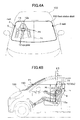
- Fig. 4A referred to in the following is a perspective view of the 1st modified example of the front window shield in Embodiment 1, associated with the eye points, and a diagram viewing down the front window shield for a vehicle from a front and obliquely upper position with respect to the vehicle.
- Fig. 4B is an illustration of the eye points, and is a side view showing the vehicle viewed from the lateral left side.
- Fig. 5A is a perspective view of the height of the marks on the front window shield for the vehicle, shown in Fig.
- Fig. 5B is a side view showing the front window shield for a vehicle, in Fig. 5A , viewed from the lateral left side of the vehicle.
- description will be made on a front window shield, for a vehicle, having a curved surface being convex outward (forward) of the vehicle.
- a front window shield 150 in the 1st modified example is provided with marks 2 and 3 at respective positions higher than the eye points 12 that correspond to the height of the eyes of a driver 11 of an ordinary body type. First, the eye points 12 will be described.
- the eye points 12 can be set, using a 50% tile manikin of an adult male (hereinafter, also referred to merely as "manikin") specified by JIS D 4607 "Three Dimensional Manikin for Use in Defining Automobile Seating Accommodation (3DM-JM 50)" or ISO 6549 "Road vehicles-Procedure for H-point determination".
- the eye points 12 can be defined as reference points in the cabin, and specifically defined by the method described in "Announcement defining details of safety standard of road trucking vehicle (Ministry of Land, Infrastructure and Transport Government of Japan) Appendix 81".
- the eye points 12 may be defined in other ways, without being limited thereto. In the present 1st modified example, as shown in Fig.
- a manikin is seated at a driver seat S at a predetermined position by a seating method specified by ISO 6549, and the height Ht of the eye points 12 is set to be vertically 635 mm above from H-point 13a (also referred to as DRP (Driver's Reference Point) ) being the hip point of the manikin.
- H-point 13a also referred to as DRP (Driver's Reference Point)
- the torso angle ⁇ 1 also referred to as a back angle
- the torso angle ⁇ 1 is 25 degrees
- the backward inclination angle ⁇ 3 of the center point 12a (refer to Fig. 4A ) between the eye points 12 is 8 degrees.
- the torso angle ⁇ 1 is not limited to 25 degrees, and may be set suitably. In this case, the positions of eye points 12 are adjusted to be the above-described reference point, corresponding to the torso angle ⁇ 1.
- the marks 2 and 3 (refer to Fig. 4A ) of the 1st modified example are arranged at a position higher than the eye points 12.
- the marks 2 and 3 are arranged, as shown in Fig. 4A , higher than an eye level point P1 provided on a left-right center line 14 of the front window shield 150 and at the same height as the eye points 12.
- the left-right center line 14 is defined on a surface of the front window shield 150 provided with the marks 2 and 3.
- the left-right center line 14 is defined also on the surface inside the vehicle, and in a case where the marks 2 and 3 are provided on the surface outside the vehicle, the left-right center line 14 is defined also on the surface outside the vehicle. Further, in a case where the marks 2 and 3 are provided for the front window shield 150, sandwiched by superimposed glass sheets, the left-right center line is defined on the joining surface between the glass sheets. Referring to a mark height point P2 defined at the same height as the marks 2 and 3 and on the left-right center line 14, a preferable height of the marks 2 and 3 is set to a height, as shown in Fig. 5A and Fig.
- center point 12b a line that connects a point 12b (hereinafter, referred to as "center point 12b") being horizontally moved from the eye-point center point 12a to the center of the vehicle with respect to the lateral direction and the eye level point P1 and a line that connects the center point 12b and the mark height point P2 is within a range of 5 to 25 degrees.
- the marks 2 and 3 and the mark height point P2 are present on the same horizontal plane 15, wherein the horizontal plane 15 and the above-described surface, of the front window shield 150, on which the marks 2 and 3 are provided, intersect with each other, forming an intersection curve being convex forward, corresponding to the curvature of the front window shield 150.
- a visible curve 15a formed on the above described surface of the front window shield 150 provided with the marks 2 and 3, the visible curve following the virtual curve 15a may be arranged to be "a mark that indicates a substantially horizontal direction" according to the above described first aspect, as the visible curve alone to take the place of the marks 2 and 3, or along with the marks 2 and 3.
- the marks 2 and 3 are formed at the same height for the front window shield 150 of the 1st modified example, the marks 2 and 3 may be formed, in the present invention, at different heights as long as the marks 2 and 3 indicate a substantially horizontal direction.
- FIG. 6A referred to here is a schematic diagram showing the movement of the line of sight at the front window shield for a vehicle, shown in Fig. 4A
- Fig. 6B is a schematic diagram showing the movement of the line of sight at a front window shield for a vehicle, as a comparative example.
- the trackings of line of sight W1 and W2 showing the movement of the line of sight in Fig. 6A and Fig. 6B were obtained, using the eye mark recorder (EMR-8 manufactured by NAC Co.).
- the driver 11 when the driver 11 (refer to Fig. 4B ) has consciously decided a horizontal line of sight at the height of the driver's eyes, the driver 11 tends to take a view of a landscape outside the vehicle substantially at the same height as the horizon. That is, in a vehicle 100 (refer to Fig. 4A ) on a horizontal road surface allowing a wide and well-seen view, the driver 11 decides the line of sight at the same height as the horizon, which is seen as a cut-end of the surface of the road far ahead.
- the front window shield 150 (refer to Fig. 6A ) can direct the line of sight of the driver 11 toward the surface of the road adjacent to the horizon Hr, compared with the conventional front window shield 150' (refer to Fig. 6B ).
- the front window shield 150 of the 1st modified example since the movement of the line of sight of the driver 11 can be concentrated on the lower side of the horizon Hr, it is possible to prevent directing the attention of the driver 11 to the range higher than the horizon Hr, as has occurred with a conventional front window shield 150' , and allows the driver 11 to stably pay attention to the road during driving the vehicle 100.
- a front window shield 150 which is convex toward outside (forward) the vehicle has been described.
- a front window shield in a flat plate shape can also be employed in the invention. In this case, a mark corresponding to the curve 15a (refer to Fig. 4A ) on the front window shield 150 in the 1st modified example is formed in a line.
- a front window shield as a 2nd modified example in Embodiment 1 will be described.
- Reference symbols 1, 4, 5, 6, 7, 8 and 9 in Figs. 7A and 7B represent the same parts as the corresponding parts shown in Fig. 1 .
- a linear mark 10A is formed on a front window shield 1.
- This linear mark 10A also may be formed of black ceramic.
- the linear mark 10A functions the same as the virtual line L by the marks 2 and 3.
- marks 10B are formed on the left side and the right side of a front window shield 1. These marks 10B are an example where the marks 2 and 3 are formed in a rectangular shape. Herein, the marks 10B are formed in a horizontally elongated rectangular shape. The same as perceiving the virtual line L by the marks 2 and 3, the driver can perceive a virtual line also with such marks as marks 10B.
- the linear marks 10A and 10B may also be formed of black ceramic.
- each of the marks 2, 3, 10B and the linear mark 10A (hereinafter, referred to as "marks 2 and the like") is formed of black ceramic at a constant position of the same height for the vehicles 100, 200B and 200A (hereinafter, referred to as "vehicle 100 and the like").
- the marks 2 and the like may be arranged to be movable up and down.
- a structure may include left and right marks 2 and the like as a structure movable relative to the front window shield 1, and a slide mechanism, not shown, for moving the marks 2 and the like up and down.
- the slide mechanism not shown, may be fitted on the front window shield 1 or the front pillars 4 and 5.
- the marks 2 and the like may be formed on the front pillars 4 and 5 without a slide mechanism.
- a front window shield in an Embodiment 2 will be described, referring to a schematic diagram, shown in Fig. 8 .
- the reference symbols 1, 4, 5, 6, 7, 8 and 9 in Fig. 8 represent the same parts as the corresponding parts, shown in Fig. 1 .
- regions 1a and 1b with a lower transmission rate are formed at the center of a lower portion and an upper portion of the front window shield 1. Therefore, the region with a higher transmission rate excluding the regions 1a and 1b with the lower transmission rate is formed substantially in an H-shape.
- any ratio may be applied for the difference as long as the difference of the regions can be recognized.
- the regions 1a and 1b may be formed such that the transmission rates are different when the regions are viewed from the driving seat side (herein, the right side).
- the regions 1a and 1b are formed by sandblasting the front window shield 1.
- any structure capable of reducing the transmission rate (resolution) may be employed.
- the regions 1a and 1b may be formed, drawing a dot pattern.
- the regions 1a and 1b may be formed by coloring or sticking a seal.
- the regions 1a and 1b are arranged to have the same transmission rate entirely inside the regions herein, the transmission rate may not be constant.
- the regions 1a and 1b may be represented only by frames in a rectangular shape.
- the driver can visually perceive with intention the circumstantial information seen through the regions 1a and 1b without any difficulty. Accordingly, there is no problem with safety. Further, also in Embodiment 2, when the driver becomes used to the regions 1a and 1b, it is expected that the driver can unconsciously move the line of sight to the H-shaped part with a high transparency during normal driving.
- the region 1a and the region 1b are formed on the upper portion and the lower portion.
- only one of the region 1a and region 1b may be formed at the center of the upper portion or the lower portion.
- the region with a higher transmission rate which excludes the region 1a or 1b with a lower transmission rate is formed substantially in a U-shape or substantially in an inverted U-shape.
- the driver moves the line of sight in the substantial U-shape, avoiding the region 1a. Therefore, in the central part of the front window shield 1, the line of sight can be concentrated on the upper side of the height of the region 1a, thereby the height of the line of sight being controlled.
- the driver moves the line of sight in the substantial inverted U-shape, avoiding the region 1b. Therefore, in the central part of the front window shield 1, the line of sight can be concentrated on the upper side of the height of the region 1b, thereby the height of the line of sight being controlled.
- the present Embodiment 2 it is understood that scattering of the line of sight is inhibited, and the driving sense is assisted.
- the phenomenon that the line of sight of a driver wastefully moves to the upper direction is inhibited except when viewing an indication or traffic signal, and also the phenomenon that the line of sight of the driver wastefully moves to the lower direction is inhibited.
- the line of sight can be directed higher than the vicinity of the vehicle and lower than the height at the vicinity of the horizon. Therefore, it is possible to avoid the situation where the driver concentrates on positioning the vehicle within a lane, and the line of sight is frequently directed to a position in the vicinity of the vehicle, which a beginning driver is apt to face.
- a front window shield for a vehicle in Embodiment 3 will be described, referring to a schematic diagram, shown in Fig. 9 .
- Reference symbols 1, 4, 5, 6, 7, 8 and 9 in Fig. 9 represent the same element as the corresponding elements shown in Fig. 1 .
- the bottom end portion B of a front window shield 1 is in a substantially horizontal linear shape when viewed from the driving seat.
- the left end of the bottom end portion B intersects a horizontal waist line A on a left front pillar 4, and the right end of the bottom end portion B intersects a waist line C on a right front pillar 5. Accordingly, the bottom end portion B, waist lines A and C are at the same height.
- the bottom end portion B is structured by a black ceramic (end assistance) 1c formed in a substantially horizontal curve which is visually perceived in a substantially horizontal linear shape when viewed from the driving seat.
- a black ceramic (end assistance) 1c formed in a substantially horizontal curve which is visually perceived in a substantially horizontal linear shape when viewed from the driving seat.
- a black ceramic 1c is formed at the bottom end of the front window shield 1, a bottom end portion B figuring a line, in such a manner that the central part is thin, and the closer to the left end or right end a position is, the larger the width of the bottom end at the position is.
- the driver can perceive a frame by the waist line A, bottom end portion B and waist line C.
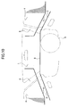
- Fig. 10 is a schematic diagram showing the state of visual perception of the sides at the front window shield shown in Fig. 9 .
- the driver who is positioning on the steering 9 side visually perceives the frame, the driver can know the length of the bottom end portion B between the waist line A and waist line C, at a distance about 1 meter from the driver, which allows the driver to estimate the vehicle width by sense perception.
- the driver can easily have the distance sense in terms of the relationship between the road width ahead and the vehicle width and the left-right distance sense, by sense perception. In such a manner, the driver is always allowed to perceive the position relationship between the own vehicle and the circumstance by the frame (comparator), while driving the vehicle. Accordingly, in the present Embodiment 3, the accuracy of the visual perception and vehicle-width perception of the driver is improved to assist the driving sense.
- the bottom end portion B is formed of black ceramic 1c
- another colorant or a seal may be used to form the bottom end portion B, the same as in Embodiment 1.
- the instrument panel 6 is formed in a linear shape, and the bottom end of the front window shield 1 is formed to be hidden from the view of the driver, then accordingly a bottom end portion B can be formed likewise.
- the black ceramic 1c and the instrument panel 6 may be used in collaboration to form a bottom end portion B.
- the bottom end portion B can be formed in a linear shape.
- the both left and right ends of the bottom end portion B intersect the left front pillar 4 and the right front pillar 5 on the respective sides such as to be visually perceived to form an edge shape at the intersections. Therefore, even with this structure, the driver is enabled to perceive the vehicle-width by the frame formed by the bottom end portion B of the front window shield 1, the left front pillar 4 and the right front pillar 5, and thus the driving sense is assisted.
- a test (position deviation test) of position deviation of the vehicle 400 was carried out during driving the vehicle 400 provided with the front window shield 1, shown in Fig. 9 , in Embodiment 3 in a circular circuit course.
- Fig. 11 referred to here, is a perspective view showing the state where the vehicle is driven in the circuit course in the position deviation test.
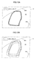
- Fig. 12A is a partial perspective view showing the state of position deviation of the outline of the vehicle made during each circuit when the vehicle provided with the front window shield in Embodiment 3 passes the region enclosed by X in Fig. 11 for plural times.
- FIG. 12B is a partial perspective view showing the state of position deviation of the outline of the vehicle made during each circuit when a vehicle provided with a front window shield as a comparative example passes the region enclosed by X in Fig. 11 for plural times.
- the front window shield as the comparative example is a conventional front window shield.with a bottom end portion thereof being located at a different height from the horizontal waist lines on the both sides.
- the circuit course 20 is arranged between an inner curve 20a being a circle with a radius of 8.5 m and an outer curve 20b being a concentric circle 4.5 m away outside from the inner line 20a.
- the driver (not shown) drove the vehicle 400 provided with the front window shield 1 in Embodiment 3 between the both curves 20a and 20b, while confirming the inner line 20a and the outer line 20b of the circuit course 20 for seven laps of the circuit.
- deviation of the outline 21 of the vehicle 400 during the rest five laps were measured for the region enclosed by X.
- the deviation of the outline 21 was measured by picking up an image of the vehicle 400 in the region enclosed by X when the vehicle 400 was detected by an optical sensor (not shown) arranged at a predetermined position of the circuit course 20.
- a window, for a vehicle having a simple and inexpensive structure that assists driving sense can be presented.
- a vehicle having a simple and inexpensive structure that assists the driving sense.
- a front window shield 1 of a vehicle 100 is provided with a pair of marks 2 and 3 substantially horizontally aligned.
- the marks 2 and 3 are formed at the same height at the left and right sides of the front window shield 1.
- a driver perceives a virtual line L by the marks 2 and 3 on the front window shield 1, and trackings of the line of sight W1 are induced to move such as to gather between the bottom end line (herein, a line of an instrument panel 6) and a virtual line L.
Landscapes
- Engineering & Computer Science (AREA)
- Mechanical Engineering (AREA)
- Window Of Vehicle (AREA)
- Body Structure For Vehicles (AREA)
Abstract
Description
- The present invention relates to a front window shield for a vehicle, having a simple and low cost structure that assists driving sense.
- Conventionally, in a known technology, a liquid crystal panel is installed on a surface at the lower portion of a front window shield (front glass) of a vehicle, and a voltage is applied to the liquid crystal panel, corresponding to the running conditions so as to lower the transmission rate of the liquid crystal panel, thereby directing the line of sight of a driver to a region where the transmission rate is higher than the liquid crystal panel (for example, refer to Patent Documents 1 (Japanese Laid-Open Utility Model Application No.
H04-90415 Figs. 1 to 5 ) and Patent Document 2 (Japanese Laid-Open Patent Application No.2000-211355 Figs. 7 and8 )). - Further, in another known technology, a corner pole is provided at an end portion of a vehicle, such as the front end portion on the front passenger seat side, so that the end portion of the vehicle being invisible directly from inside the vehicle can be predicted with the assistance of the corner pole being visible through the front window shield (for example, refer to Patent Document 3 (Japanese Laid-Open Patent Application No.
H06-127313 Figs. 1 and7 )). In still another known technology, a camera is provided at an end portion of a vehicle and the camera picks up an image of the end portion of the vehicle so as to display the image on a display in the vehicle (for example, refer to Patent Document 4 (Japanese Laid-Open Patent Application No.H08-225043 Figs. 1 and7 )). - In the technologies described in the
above Patent Documents - Further, in the technologies described in the
above Patent Documents above Patent Document 3, when the corner pole is not used, the corner pole is controlled to be put into the vehicle by electrical operation, which requires wiring and a controller, causing a high cost. Still further, in the technology described in theabove Patent Document 4, displaying an image picked up by a camera on a display in a vehicle requires wiring and a display, causing a high cost. - Addressing problems as described above, an object of the invention is to provide a front window shield for a vehicle, having a simple and inexpensive structure for assisting driving sense.
- In a first aspect of the invention, there is provided a front window shield for a vehicle, located at a front part of the vehicle and configured to secure a view of a driver in the vehicle, the front window shield including a window shield having at least one mark indicating a substantially horizontal direction. In this constitution, a simple and inexpensive structure including at least one mark enables a driver to move the line of sight with a substantially horizontal line be a reference, which inhibits scattering of the line of sight and assists the driving sense.
- In a second aspect of the invention, the front window shield for a vehicle in the first aspect includes a pair of the marks formed on both a right side and left side. In this constitution, the driver feels as if a virtual line is present connecting the right and left marks, and movement of the line of sight is provided with the virtual line as a reference, which inhibits scattering of the line of sight and assists the driving sense.
- Since the driver can unconsciously or consciously perceive the virtual line, the line of sight is prevented from scattering to the upper side of the virtual line, and assists the driving sense such that the line of sight concentrates on the lower side of the virtual line. Further, just the perception by the driver of the virtual line prevents scattering up and down of the line of sight and assists the driving sense such that the line of sight moves along the virtual line. Further, just arranging the marks on the front window shield to make the virtual line perceivable does not interfere with the confirmation by the driver of a traffic signal or the like in the upper direction.
- In this constitution, a simple structure that forms a pair of marks at the same height position on the right and left sides of the front window shield for a vehicle can easily assist the driving sense of the vehicle.
- In a third aspect of the invention, for the front window shield for a vehicle in the second aspect, each of the pair of the marks is shaped in a triangle formed of a base along a front pillar and an apex off and opposite the base. In this constitution, the apexes of the right and left marks serve as arrows indicating a direction, which allows easy perception of a substantially horizontal virtual line connecting the left and right apexes.
- In a fourth aspect of the invention, for the front window shield for a vehicle in the first aspect, the at least one mark is formed as a substantially horizontal line connecting a right end and left end of the front window shield. In this constitution, movement of the line of sight is promoted with the line formed on the front window shield as a reference similarly to a virtual line, which inhibits scattering of the line of sight and assists the driving sense.
- In a fifth aspect of the invention, for the front window shield for a vehicle in the second or third aspect, the pair of the marks are arranged at positions higher than an eye point of the driver. In this constitution, the movement of the line of sight of the driver concentrates on the lower side of the horizon, which prevents directing the driver's attention to the range upper than the horizon as has occurred with a conventional front window shield, and allows the driver to stably pay attention to the road during running the vehicle.
- In a sixth aspect of the invention, there is provided a front window shield for a vehicle, located at a front part of the vehicle and configured to secure a view of a driver in the vehicle, the front window shield including: a region with a lower transmission rate formed at a center of an upper portion or a lower portion of the front window shield; and a region with a higher transmission rate formed substantially in a U-shape or substantially in an inverted U-shape.
- In this constitution, since a region with a higher transmission rate is formed substantially in a U-shape or substantially in an inverted U-shape, it is possible to direct the line of sight such as to avoid a substantially rectangular region with a lower transmission rate, thereby assisting the driving sense. Therefore, the height of the line of sight passing the center of the front window shield can be controlled, thereby inducing appropriate perception of the circumstances.
- In a seventh aspect of the invention, there is provided a front window shield for a vehicle, located at a front part of the vehicle and configured to secure a view of a driver in the vehicle, the front window shield including regions with a lower transmission rate formed at a center of an upper portion and at a center of a lower portion of the front window shield; and a region with a higher transmission rate formed substantially in an H-shape.
- In this constitution, since the region with a higher transmission rate is formed substantially in an H-shape, movement of the line of sight is directed to the region with a higher transmission rate substantially in an H-shape, thereby assisting the driving sense. Particularly at the center of the front window shield, the line of sight is induced to move horizontally, passing the substantially I-shape portion (a horizontal bar of the substantial H-shape), thereby directing the line of sight to a range higher than the vicinity of the vehicle and lower than the height adj acent to the horizon. Thus, the height of the line of sight passing the center of the front window shield can be controlled, thereby inducing appropriate perception of the circumstances.
- In an eighth aspect of the invention, there is provided a front window shield for a vehicle, located at a front part of the vehicle and configured to secure a view of a driver in the vehicle, the front window shield including a bottom end portion being in a substantially-horizontal linear shape and disposed at a height same as horizontal waist lines on both sides.
- In this constitution, since a frame formed by the bottom end portion of the front window shield and the waist lines enables guessing of the vehicle width by the lateral portions or the front portion of the vehicle, thereby assisting the driving sense of the driver. Therefore, the frame can be used as a reference (comparator) for comparison between the circumstances and the vehicle.
- Herein, as the frame is formed adjacent to the driving seat, it is easy to sensuously perceive the vehicle width. Thus, the driver can easily have the sense of distance to a building or wall on a side. Further, the driver can imagine extension lines forward from the waist lines and imagine the crossing with a horizon so as to be able to guess the vehicle width far ahead. Thus, the driver can perceive the position relationship between the own vehicle and the surrounding circumstances. Further, in this constitution, it is possible to construct an end assistance (an assistance at the bottom end) without fitting an additional part, such as a corner pole, and just by changing a shape of the structure already used in the vehicle.
- In a ninth aspect of the invention, there is provided a front window shield for a vehicle, located at a front part of the vehicle and configured to secure a view of a driver in the vehicle, the front window shield including: a bottom end portion being formed in a substantially-horizontal curved shape and having an end assistance so that the bottom end portion is visually perceived in a substantially-horizontal linear shape when viewed from a driver seat. In this constitution, a frame formed by the end assistance at the bottom end portion of the front window shield and the waist lines enables guessing of the vehicle width at the side or the front, thus assisting the driving sense. Therefore, the frame can be used as a reference (comparator) for comparison between the circumstances and the vehicle.
- In a tenth aspect of the invention, a front window shield for a vehicle, located at a front part of the vehicle and configured to secure a view of a driver in the vehicle, the front window shield including: a bottom end portion being in a substantially-horizontal linear shape, wherein both left and right ends of the bottom end portion are crossed with respective front pillars on both sides in such a manner that both the left and right ends of the bottom end portion and the respective front pillars are visually perceived to form respective edge shapes. In this constitution, a frame formed by the end assistance at the bottom end portion and the front pillars enables the driver to perceive the vehicle width, thus assisting the driving sense. Therefore, the frame can be used as a reference (comparator) for comparison between the circumstances and the vehicle.
-
-
Fig. 1 is a schematic diagram showing a front window shield for a vehicle inEmbodiment 1; -
Fig. 2 is a partial schematic diagram showing the right side of the front window shield, shown inFig. 1 , including an enlarged view of a mark; -
Fig. 3A is a schematic diagram showing the movement of the line of sight on the front window shield for a vehicle, shown inFig. 1 ; -
Fig. 3B is a schematic diagram showing the movement of the line of sight on a front window shield for a vehicle as a comparative example; -
Fig. 4A is a perspective view showing a 1st modified example of the front window shield for a vehicle inEmbodiment 1, in association with eye points, wherein the front window shield for a vehicle is viewed down from a front and obliquely upper position with respect to the vehicle; -
Fig. 4B is an illustration of the eye points, being a side view of the front window shield viewed from the left side of the vehicle; -
Fig. 5A is a perspective view showing the height of marks on a front window shield for a vehicle, inFig. 4A , in association with eye points, wherein the front window shield for a vehicle is viewed down from a front and obliquely upper position with respect to the window; -
Fig. 5B is a side view of the front window shield for a vehicle inFig. 5A , viewed from the left side of the vehicle; -
Fig. 6A is a schematic diagram showing the movement of the line of sight on the front window shield for a vehicle, shown inFig. 4A ; -
Fig. 6B is a schematic diagram showing the movement of the line of sight on the front window shield for a vehicle, as a comparative example; -
Fig. 7A is a schematic diagram showing a front window shield for a vehicle, as a 2nd modified example; -
Fig. 7B is a schematic diagram showing a front window shield for a vehicle, as a 2nd modified example; -
Fig. 8 is a schematic diagram showing a front window shield for a vehicle in anembodiment 2; -
Fig. 9 is a schematic diagram showing a front window shield for a vehicle in anembodiment 3; -
Fig. 10 is a schematic diagram showing the state of visual perception of the sides of the front window shield for a vehicle, shown in Fug. 9; -
Fig. 11 is a perspective view showing the state where a vehicle is driving in a circuit course in a position deviation test; -
Fig. 12A is a partial perspective view showing the state of position deviation of the outline of the vehicle made during each circuit when the vehicle provided with the front window shield inEmbodiment 3 passes the region enclosed by X inFig. 11 for plural times; and -
Fig. 12B is a partial perspective view showing the state of position deviation of the outline of the vehicle made during each circuit when a vehicle provided with a front window shield as a comparative example passes the region enclosed by X inFig. 11 for plural times. - Embodiments of the present invention will be described, referring to the drawings.
- First, a front window shield for a vehicle in
Embodiment 1 will be described, referring to a schematic diagram, shown inFig.1 . Herein, description will be made for a case where a vehicle is on a horizontal road surface. - As shown in
Fig. 1 , for avehicle 100, a front window shield for a vehicle (hereinafter also referred to as "a front window shield") 1 is provided with a pair ofmarks marks marks - The
marks front window shield 1 or the like, a part of the left and right ends is made into a pair of isosceles triangles, so as to formmarks front window shield 1. Although in thepresent Embodiment 1, black ceramic is employed to form themarks marks front window shield 1 with an arbitrary dye or by sticking a seal- formed body on thefront window shield 1 as long as such a shape can be formed. - The schematic diagram, shown in
Fig. 1 , mainly shows a leftfront pillar 4 and rightfront pillar 5 which support thefront window shield 1 at the left and right, aninstrument panel 6,doors steering 9. In thepresent Embodiment 1, a right-hand steering vehicle is exemplarily shown. - Now, referring to the schematic diagram shown in
Fig. 2 , the front window shield shown inFig. 1 will be described. As shown inFig. 2 , themark 3 is shaped in a triangle formed of a base along a rightfront pillar 5 supporting thefront window shield 1, and an apex off and opposite the base. Particularly, herein, themark 3 is formed in an isosceles triangle. Thismark 3 is satisfactory, for example, with an isosceles triangle defined by a base of approximately 4. 0 mm and the other two sides of approximately 2.0 mm. Themark 2, shown inFig. 1 , is formed in an isosceles triangle being a line symmetry of themark 3 with respect to the vertical line. Accordingly, description of themark 2 is omitted. - Although in the
present Embodiment 1, the pair ofmarks marks present Embodiment 1, one pair ofmarks marks - Further, the virtual line may be a conceptual line, without limitation of a Euclid geometrical width, but is a concept containing a band form with a limited width. In the
present Embodiment 1, it is possible to perceive a band form approximately in the same width as the width of the base portions of themarks - Further, although in the
present Embodiment 1, themarks front window shield 1, themarks present Embodiment 1, a pair ofmarks marks front window shield 1 into three parts from the top to the bottom. - Now, a moving state of the line of sight on the
front window shield 1, shown inFig. 1 , will be described, referring toFig. 3. Fig. 3A is a schematic diagram showing the movement of the line of sight on the front window shield, shown inFig. 1 , whileFig. 3B is a schematic diagram showing the movement of the line of sight on a front window shield in a comparative example of thepresent Embodiment 1. Herein, trackings of line of sight W1 and W2 showing the movement of the line of sight inFig. 3A and Fig. 3B were obtained, using an eye mark recorder (EMR-8 manufactured by NAC Co.). - As shown in
Fig. 3A , inEmbodiment 1, the driver consciously or unconsciously perceives a virtual line L by themarks front window shield 1 so that the trackings of line of sight W1 move to gather between the bottom end line (herein, the line of the instrument panel 6) of thefront window shield 1 and the virtual line L. Particularly, the line of sight moving in the left/right direction becomes substantially horizontal with less up-down movement. That is, by thefront window shield 1 inEmbodiment 1, it is possible to make the line of sight of the driver concentrate on the lower side of themarks - Further, when the driver has become used to the
marks - On the other hand, since the vehicle 100' , shown in
Fig. 3B , is not provided withmarks Fig. 3A and the tracking of line of sight W2 inFig. 3B are compared, it is understood inEmbodiment 1 that scattering of the line of sight is inhibited and the driving sense is assisted. Therefore, the phenomenon that the line of sight of a driver wastefully moves upward is inhibited except when viewing an indication or traffic signal. - Now, a 1st modified example of the front window shield (refer to
Fig. 1 ) inEmbodiment 1 will be described.Fig. 4A referred to in the following is a perspective view of the 1st modified example of the front window shield inEmbodiment 1, associated with the eye points, and a diagram viewing down the front window shield for a vehicle from a front and obliquely upper position with respect to the vehicle.Fig. 4B is an illustration of the eye points, and is a side view showing the vehicle viewed from the lateral left side.Fig. 5A is a perspective view of the height of the marks on the front window shield for the vehicle, shown inFig. 4A , in association with the eye points of the driver, and a view showing the front window shield for a vehicle viewed down from the front and obliquely upper position with respect to the vehicle.Fig. 5B is a side view showing the front window shield for a vehicle, inFig. 5A , viewed from the lateral left side of the vehicle. Here, description will be made on a front window shield, for a vehicle, having a curved surface being convex outward (forward) of the vehicle. For structural elements same as inEmbodiment 1 will be given with the same reference symbols, and detailed description of which will be omitted. - As shown in
Fig. 4A , afront window shield 150 in the 1st modified example is provided withmarks driver 11 of an ordinary body type. First, the eye points 12 will be described. - The eye points 12 can be set, using a 50% tile manikin of an adult male (hereinafter, also referred to merely as "manikin") specified by JIS D 4607 "Three Dimensional Manikin for Use in Defining Automobile Seating Accommodation (3DM-JM 50)" or ISO 6549 "Road vehicles-Procedure for H-point determination".
The eye points 12 can be defined as reference points in the cabin, and specifically defined by the method described in "Announcement defining details of safety standard of road trucking vehicle (Ministry of Land, Infrastructure and Transport Government of Japan) Appendix 81". However, the eye points 12 may be defined in other ways, without being limited thereto.
In the present 1st modified example, as shown inFig. 4B , a manikin is seated at a driver seat S at a predetermined position by a seating method specified by ISO 6549, and the height Ht of the eye points 12 is set to be vertically 635 mm above from H-point 13a (also referred to as DRP (Driver's Reference Point) ) being the hip point of the manikin. In the 1st modified example, the torso angle θ1 (also referred to as a back angle) is 25 degrees, and when the torso angle θ1 is 25 degrees, the backward inclination angle θ3 of thecenter point 12a (refer toFig. 4A ) between the eye points 12 is 8 degrees. The torso angle θ1 is not limited to 25 degrees, and may be set suitably. In this case, the positions of eye points 12 are adjusted to be the above-described reference point, corresponding to the torso angle θ1. - As described above, the
marks 2 and 3 (refer toFig. 4A ) of the 1st modified example are arranged at a position higher than the eye points 12. In other words, as described above, for thevehicle 100 on a horizontal road surface, themarks Fig. 4A , higher than an eye level point P1 provided on a left-right center line 14 of thefront window shield 150 and at the same height as the eye points 12. Herein, the left-right center line 14 is defined on a surface of thefront window shield 150 provided with themarks marks right center line 14 is defined also on the surface inside the vehicle, and in a case where themarks right center line 14 is defined also on the surface outside the vehicle. Further, in a case where themarks front window shield 150, sandwiched by superimposed glass sheets, the left-right center line is defined on the joining surface between the glass sheets. Referring to a mark height point P2 defined at the same height as themarks right center line 14, a preferable height of themarks Fig. 5A and Fig. 5B , where the angle θ2 defined by a line that connects apoint 12b (hereinafter, referred to as "center point 12b") being horizontally moved from the eye-point center point 12a to the center of the vehicle with respect to the lateral direction and the eye level point P1 and a line that connects thecenter point 12b and the mark height point P2 is within a range of 5 to 25 degrees. - Herein, the
marks horizontal plane 15, wherein thehorizontal plane 15 and the above-described surface, of thefront window shield 150, on which themarks front window shield 150.
Avisible curve 15a formed on the above described surface of thefront window shield 150 provided with themarks virtual curve 15a, may be arranged to be "a mark that indicates a substantially horizontal direction" according to the above described first aspect, as the visible curve alone to take the place of themarks marks marks front window shield 150 of the 1st modified example, themarks marks - Next, functions and effects of the
front window shield 150 in the 1st modified example will be described below.Fig. 6A referred to here is a schematic diagram showing the movement of the line of sight at the front window shield for a vehicle, shown inFig. 4A , whileFig. 6B is a schematic diagram showing the movement of the line of sight at a front window shield for a vehicle, as a comparative example. The trackings of line of sight W1 and W2 showing the movement of the line of sight inFig. 6A and Fig. 6B were obtained, using the eye mark recorder (EMR-8 manufactured by NAC Co.). - In general, when the driver 11 (refer to
Fig. 4B ) has consciously decided a horizontal line of sight at the height of the driver's eyes, thedriver 11 tends to take a view of a landscape outside the vehicle substantially at the same height as the horizon. That is, in a vehicle 100 (refer toFig. 4A ) on a horizontal road surface allowing a wide and well-seen view, thedriver 11 decides the line of sight at the same height as the horizon, which is seen as a cut-end of the surface of the road far ahead. - Concretely, as shown in
Fig. 6B for example, with a conventional front window shield 150' (the comparative example) withoutmarks Fig. 4B ) comes to see the horizon Hr through the front window shield 150' by a horizontal line of sight. In this situation, the inventors confirmed the following fact. That is, when thedriver 11 runs a vehicle 100' having such a front window shield 150' , the driver perceives the landscape seen through the front window shield 150' , wherein the landscape is perceived to be moving relatively, which greatly scatters the tracking of line of sight W2 of thedriver 11 up and down on the front window shield 150' with the horizon Hr be the boundary. - On the other hand, as shown in
Fig. 6A , with thefront window shield 150, of the 1st modified example, provided with themarks Fig. 4A ), the tracking of line of sight W1 of the driver (refer toFig, 4B ) concentrates on the lower side of the horizon Hr, which was proved by measurement of the line of sight, using the above-described eye mark recorder. Particularly, from the fact that the tracking of line of sight W1 concentrates on the lower side of the horizon Hr even in the left-right central part (central part) of thefront window shield 150, it is understood that thedriver 11 consciously or unconsciously perceives the virtual line L connecting themarks Fig. 6A ) can direct the line of sight of thedriver 11 toward the surface of the road adjacent to the horizon Hr, compared with the conventional front window shield 150' (refer toFig. 6B ). - By the
front window shield 150 of the 1st modified example, since the movement of the line of sight of thedriver 11 can be concentrated on the lower side of the horizon Hr, it is possible to prevent directing the attention of thedriver 11 to the range higher than the horizon Hr, as has occurred with a conventional front window shield 150' , and allows thedriver 11 to stably pay attention to the road during driving thevehicle 100.
In the 1st modified example, afront window shield 150 which is convex toward outside (forward) the vehicle has been described. However, a front window shield in a flat plate shape can also be employed in the invention. In this case, a mark corresponding to thecurve 15a (refer toFig. 4A ) on thefront window shield 150 in the 1st modified example is formed in a line. - Next, referring to the schematic views shown in
Figs. 7A and 7B , a front window shield as a 2nd modified example inEmbodiment 1 will be described.Reference symbols Figs. 7A and 7B represent the same parts as the corresponding parts shown inFig. 1 . As shown inFig. 7A , for avehicle 200A, alinear mark 10A is formed on afront window shield 1. Thislinear mark 10A also may be formed of black ceramic. As a driver can visually perceive thehorizontal liner mark 10A, thelinear mark 10A functions the same as the virtual line L by themarks - As shown in
Fig. 7B , for avehicle 200B, marks 10B are formed on the left side and the right side of afront window shield 1. Thesemarks 10B are an example where themarks marks 10B are formed in a horizontally elongated rectangular shape. The same as perceiving the virtual line L by themarks marks 10B. Thelinear marks - In the above description, each of the
marks linear mark 10A (hereinafter, referred to as "marks 2 and the like") is formed of black ceramic at a constant position of the same height for thevehicles vehicle 100 and the like"). However, themarks 2 and the like may be arranged to be movable up and down. For example, a structure may include left andright marks 2 and the like as a structure movable relative to thefront window shield 1, and a slide mechanism, not shown, for moving themarks 2 and the like up and down. Such a structure enables adjustment of the height of themarks 2 and the like, corresponding to the height of the sitting height of the driver or the height of the seat. In this case, the slide mechanism, not shown, may be fitted on thefront window shield 1 or thefront pillars marks 2 and the like may be formed on thefront pillars - Now, a front window shield in an
Embodiment 2 will be described, referring to a schematic diagram, shown inFig. 8 . Thereference symbols Fig. 8 represent the same parts as the corresponding parts, shown inFig. 1 . For avehicle 300,regions front window shield 1. Therefore, the region with a higher transmission rate excluding theregions - Regarding the difference in the transmission rate between the region with the higher transmission rate and the regions with the lower transmission rate, any ratio may be applied for the difference as long as the difference of the regions can be recognized. Further, the
regions regions front window shield 1. However, without limited thereto, any structure capable of reducing the transmission rate (resolution) may be employed. For example, theregions regions regions regions - Next, the moving state of the line of sight on the
front window shield 1, shown inFig. 8 , will be described. The tracking of line of sight W3 showing the movement of the line of sight, shown inFig. 8 , was obtained, using the eye mark recorder ((EMR-8 manufactured by NAC Co.). In this case, the driver perceives theregions front window shield 1, and when the line of sight moves in the central part of thefront window shield 1, the line of sight draws the tracking of line of sight W3, avoiding theregions front window shield 1, and thus the height of the line of sight being controlled. On the other hand, in a case whereregions front window shield 1, the line of sight scatters, drawing the tracking of line of sight W2, as shown inFig. 3B . - Further, since the
regions regions Embodiment 2, when the driver becomes used to theregions - In the
present Embodiment 2, although a case where both theregion 1a and theregion 1b are formed on the upper portion and the lower portion has been described, only one of theregion 1a andregion 1b may be formed at the center of the upper portion or the lower portion. In this case, the region with a higher transmission rate which excludes theregion - When only the
region 1a is formed, the driver moves the line of sight in the substantial U-shape, avoiding theregion 1a. Therefore, in the central part of thefront window shield 1, the line of sight can be concentrated on the upper side of the height of theregion 1a, thereby the height of the line of sight being controlled. - When only the
region 1b is formed, the driver moves the line of sight in the substantial inverted U-shape, avoiding theregion 1b. Therefore, in the central part of thefront window shield 1, the line of sight can be concentrated on the upper side of the height of theregion 1b, thereby the height of the line of sight being controlled. - Accordingly, in the
present Embodiment 2, it is understood that scattering of the line of sight is inhibited, and the driving sense is assisted. Thus, the phenomenon that the line of sight of a driver wastefully moves to the upper direction is inhibited except when viewing an indication or traffic signal, and also the phenomenon that the line of sight of the driver wastefully moves to the lower direction is inhibited. Also, the line of sight can be directed higher than the vicinity of the vehicle and lower than the height at the vicinity of the horizon. Therefore, it is possible to avoid the situation where the driver concentrates on positioning the vehicle within a lane, and the line of sight is frequently directed to a position in the vicinity of the vehicle, which a beginning driver is apt to face. - Now, a front window shield for a vehicle in
Embodiment 3 will be described, referring to a schematic diagram, shown inFig. 9 .Reference symbols Fig. 9 represent the same element as the corresponding elements shown inFig. 1 . For avehicle 400, the bottom end portion B of afront window shield 1 is in a substantially horizontal linear shape when viewed from the driving seat. The left end of the bottom end portion B intersects a horizontal waist line A on a leftfront pillar 4, and the right end of the bottom end portion B intersects a waist line C on a rightfront pillar 5. Accordingly, the bottom end portion B, waist lines A and C are at the same height. - The bottom end portion B is structured by a black ceramic (end assistance) 1c formed in a substantially horizontal curve which is visually perceived in a substantially horizontal linear shape when viewed from the driving seat. As the
front window shield 1 is formed in a curved surface being convex forward, the bottom end of thisfront window shield 1 figures a curve. A black ceramic 1c is formed at the bottom end of thefront window shield 1, a bottom end portion B figuring a line, in such a manner that the central part is thin, and the closer to the left end or right end a position is, the larger the width of the bottom end at the position is. Thus, the driver can perceive a frame by the waist line A, bottom end portion B and waist line C. - Next, a method of visually perceiving the circumstance outside the vehicle by the use of the frame will be described.
Fig. 10 is a schematic diagram showing the state of visual perception of the sides at the front window shield shown inFig. 9 . When the driver who is positioning on thesteering 9 side visually perceives the frame, the driver can know the length of the bottom end portion B between the waist line A and waist line C, at a distance about 1 meter from the driver, which allows the driver to estimate the vehicle width by sense perception. - Then, comparing a line X1 of the left building X and the waist line A, comparing a line Y1 of the right building Y and the waist line C, and taking into account the length of the bottom end portion B (vehicle width), the driver can easily have the distance sense in terms of the relationship between the road width ahead and the vehicle width and the left-right distance sense, by sense perception. In such a manner, the driver is always allowed to perceive the position relationship between the own vehicle and the circumstance by the frame (comparator), while driving the vehicle. Accordingly, in the
present Embodiment 3, the accuracy of the visual perception and vehicle-width perception of the driver is improved to assist the driving sense. - In the
present embodiment 3, although the bottom end portion B is formed of black ceramic 1c, another colorant or a seal may be used to form the bottom end portion B, the same as inEmbodiment 1. Further, if theinstrument panel 6 is formed in a linear shape, and the bottom end of thefront window shield 1 is formed to be hidden from the view of the driver, then accordingly a bottom end portion B can be formed likewise. Further, the black ceramic 1c and theinstrument panel 6 may be used in collaboration to form a bottom end portion B. When thefront window shield 1 is in a flat-plate shape, the bottom end portion B can be formed in a linear shape. - Since the bottom end portion B of the front window shield is in a substantially horizontal linear shape, as described above, the both left and right ends of the bottom end portion B intersect the left
front pillar 4 and the rightfront pillar 5 on the respective sides such as to be visually perceived to form an edge shape at the intersections. Therefore, even with this structure, the driver is enabled to perceive the vehicle-width by the frame formed by the bottom end portion B of thefront window shield 1, the leftfront pillar 4 and the rightfront pillar 5, and thus the driving sense is assisted. - Next, a test (position deviation test) of position deviation of the
vehicle 400 was carried out during driving thevehicle 400 provided with thefront window shield 1, shown inFig. 9 , inEmbodiment 3 in a circular circuit course.Fig. 11 , referred to here, is a perspective view showing the state where the vehicle is driven in the circuit course in the position deviation test.Fig. 12A is a partial perspective view showing the state of position deviation of the outline of the vehicle made during each circuit when the vehicle provided with the front window shield inEmbodiment 3 passes the region enclosed by X inFig. 11 for plural times.Fig. 12B is a partial perspective view showing the state of position deviation of the outline of the vehicle made during each circuit when a vehicle provided with a front window shield as a comparative example passes the region enclosed by X inFig. 11 for plural times. Herein, the front window shield as the comparative example is a conventional front window shield.with a bottom end portion thereof being located at a different height from the horizontal waist lines on the both sides. - As shown in
Fig. 11 , thecircuit course 20 is arranged between aninner curve 20a being a circle with a radius of 8.5 m and anouter curve 20b being a concentric circle 4.5 m away outside from theinner line 20a.
During the position deviation test described-above, at first, the driver (not shown) drove thevehicle 400 provided with thefront window shield 1 inEmbodiment 3 between the bothcurves inner line 20a and theouter line 20b of thecircuit course 20 for seven laps of the circuit. Then, excluding the first and seventh lap, deviation of theoutline 21 of thevehicle 400 during the rest five laps were measured for the region enclosed by X. Herein, the deviation of theoutline 21 was measured by picking up an image of thevehicle 400 in the region enclosed by X when thevehicle 400 was detected by an optical sensor (not shown) arranged at a predetermined position of thecircuit course 20. - Next, another position deviation test was carried out in the same manner as that for the
vehicle 400 except that a vehicle 400' provided with the front window shield as the comparative example described-above was used instead of thevehicle 400. The result is shown inFig. 12B . - As apparent from the comparison between
Fig. 12A and Fig. 12B , it was confirmed that the deviation of theoutline 21 of thevehicle 400 provided with thefront window shield 1 inEmbodiment 3 is extremely smaller than the deviation of theoutline 21 of the vehicle 400' provided with the front window shield as the comparative example. It is understood that the driver (not shown) has become always able to perceive the position relationship between the vehicle 400 (refer toFig. 11 ) and the circumstance (theinner curve 20a and theouter curve 20b) by the frame (comparator) formed by the bottom end portion B and the waistlines A and C, shown inFig. 9 . In other words, it was confirmed that thefront window shield 1, inEmbodiment 3, on which a frame (comparator) is formed near the driving seat enabled the driver to easily know the vehicle width by sense perception. - As described above, according to the invention, a window, for a vehicle, having a simple and inexpensive structure that assists driving sense can be presented.
There is provided a vehicle having a simple and inexpensive structure that assists the driving sense. Afront window shield 1 of avehicle 100 is provided with a pair ofmarks marks front window shield 1. A driver perceives a virtual line L by themarks front window shield 1, and trackings of the line of sight W1 are induced to move such as to gather between the bottom end line (herein, a line of an instrument panel 6) and a virtual line L.
Claims (11)
- A front window shield for a vehicle, located at a front part of the vehicle and configured to secure a view of a driver in the vehicle, comprising:a window shield including at least one mark indicating a substantially horizontal direction.
- The front window shield for a vehicle of claim 1, wherein the front window shield includes a pair of the marks formed on both a right side and left side.
- The front window shield for a vehicle of claim 2, wherein each of the pair of the marks is shaped in a triangle formed of a base along a front pillar and an apex off and opposite the base.
- The front window shield for a vehicle of claim 1, wherein the at least one mark is formed as a substantially-horizontal line connecting a right end and left end of the front window shield.
- The front window shield for a vehicle of claim 2, wherein the pair of the marks are arranged at positions higher than an eye point of the driver.
- The front window shield for a vehicle of claim 3, wherein the pair of the marks are arranged at positions higher than an eye point of the driver.
- A front window shield for a vehicle, located at a front part of the vehicle and configured to secure a view of a driver in the vehicle, comprising:a region with a lower transmission rate formed at a center of an upper portion or a lower portion of the front window shield; anda region with a higher transmission rate formed substantially in a U-shape or substantially in an inverted U-shape.
- A front window shield for a vehicle, located at a front part of the vehicle and configured to secure a view of a driver in the vehicle, comprising:regions with a lower transmission rate formed at a center of an upper portion and at a center of a lower portion of the front window shield; anda region with a higher transmission rate formed substantially in an H-shape.
- A front window shield for a vehicle, located at a front part of the vehicle and configured to secure a view of a driver in the vehicle, comprising:a bottom end portion being in a substantially-horizontal linear shape and disposed at a height same as horizontal waist lines on both sides.
- A front window shield for a vehicle, located at a front part of the vehicle and configured to secure a view of a driver in the vehicle, comprising:a bottom end portion being formed in a substantially-horizontal curved shape and having an end assistance so that the bottom end portion is visually perceived in a substantially-horizontal linear shape when viewed from a driver seat.
- A window shield for a vehicle, located at a front part of the vehicle and configured to secure a view of a driver in the vehicle, comprising:a bottom end portion being in a substantially-horizontal linear shape, wherein both left and right ends of the bottom end portion are crossed with respective front pillars on both sides in such a manner that both the left and right ends of the bottom end portion and the respective front pillars are visually perceived to form respective edge shapes.
Applications Claiming Priority (2)
| Application Number | Priority Date | Filing Date | Title |
|---|---|---|---|
| JP2007034461 | 2007-02-15 | ||
| JP2007221965A JP5001753B2 (en) | 2007-02-15 | 2007-08-29 | Vehicle front window |
Publications (2)
| Publication Number | Publication Date |
|---|---|
| EP1958820A1 true EP1958820A1 (en) | 2008-08-20 |
| EP1958820B1 EP1958820B1 (en) | 2012-01-04 |
Family
ID=39201570
Family Applications (1)
| Application Number | Title | Priority Date | Filing Date |
|---|---|---|---|
| EP08002745A Ceased EP1958820B1 (en) | 2007-02-15 | 2008-02-14 | Front windscreens for vehicles |
Country Status (2)
| Country | Link |
|---|---|
| US (1) | US8007022B2 (en) |
| EP (1) | EP1958820B1 (en) |
Families Citing this family (5)
| Publication number | Priority date | Publication date | Assignee | Title |
|---|---|---|---|---|
| JP5594246B2 (en) * | 2011-07-20 | 2014-09-24 | 株式会社デンソー | Lane recognition device |
| FR3012071B1 (en) * | 2013-10-23 | 2021-01-01 | Saint Gobain | THIN LAMINATED GLASS |
| JP6191573B2 (en) * | 2014-09-29 | 2017-09-06 | マツダ株式会社 | Vehicle visibility adjustment device |
| JP6047208B1 (en) * | 2015-08-19 | 2016-12-21 | 本田技研工業株式会社 | Front windshield |
| JP2019135122A (en) * | 2018-02-05 | 2019-08-15 | トヨタ自動車株式会社 | Vehicle light shielding structure |
Citations (12)
| Publication number | Priority date | Publication date | Assignee | Title |
|---|---|---|---|---|
| FR590892A (en) | 1924-02-27 | 1925-06-24 | Dalemont & Cie | Magneto for ignition of explosion engines |
| US5111329A (en) * | 1990-11-28 | 1992-05-05 | Ford Motor Company | Solar load reduction panel with controllable light transparency |
| DE4128717A1 (en) * | 1991-08-29 | 1993-03-04 | Bosch Gmbh Robert | GLIDING PROTECTION ON VEHICLE WINDOWS |
| JP2002087060A (en) * | 2000-09-11 | 2002-03-26 | Inoac Corp | Vehicular glare proof device |
| GB2371912A (en) * | 2001-01-31 | 2002-08-07 | Mark Watts | A vehicle driving aid |
| US20030151272A1 (en) * | 2002-02-08 | 2003-08-14 | Akiyoshi Sugimoto | Window glass and automobile equipped with the same |
| GB2393698A (en) | 2002-10-04 | 2004-04-07 | Charles Hannant | Device with stopping distance markings applicable to windscreen |
| DE102004007521A1 (en) * | 2003-08-04 | 2005-02-24 | Robert Bosch Gmbh | Glare protection system for a vehicle |
| US20050068629A1 (en) * | 2003-09-26 | 2005-03-31 | Primal Fernando | Adjustably opaque window |
| US20050231336A1 (en) * | 2004-02-23 | 2005-10-20 | Sven Strohband | Vehicle |
| US20060175859A1 (en) * | 2005-02-10 | 2006-08-10 | Isaac Emad S | Selective light attenuation system |
| DE102005007427A1 (en) | 2005-02-18 | 2006-08-31 | Volkswagen Ag | Electric sun visor for a motor vehicle |
Family Cites Families (8)
| Publication number | Priority date | Publication date | Assignee | Title |
|---|---|---|---|---|
| US1156578A (en) * | 1913-09-20 | 1915-10-12 | Louis A Benecke | Light-obstructer. |
| JP2909168B2 (en) | 1990-08-01 | 1999-06-23 | 三菱重工業株式会社 | Clinker monitoring device |
| JPH06127313A (en) | 1992-10-22 | 1994-05-10 | Stanley Electric Co Ltd | Control device for electric vehicle parts |
| JPH08225043A (en) | 1995-02-20 | 1996-09-03 | Tokai Rika Co Ltd | Vision field auxiliary device for vehicle |
| JP2000211355A (en) | 1999-01-21 | 2000-08-02 | Isuzu Motors Ltd | Method and apparatus for restricting visibility of vehicle |
| US6107943A (en) * | 1999-04-16 | 2000-08-22 | Rockwell Collins, Inc. | Display symbology indicating aircraft ground motion deceleration |
| DE10102938B4 (en) * | 2001-01-23 | 2007-10-11 | Eurocopter Deutschland Gmbh | Pitch attitude symbolism |
| US6688007B2 (en) * | 2001-10-31 | 2004-02-10 | Steven Ferron | Lane alignment driving aid |
-
2008
- 2008-02-11 US US12/069,561 patent/US8007022B2/en active Active
- 2008-02-14 EP EP08002745A patent/EP1958820B1/en not_active Ceased
Patent Citations (12)
| Publication number | Priority date | Publication date | Assignee | Title |
|---|---|---|---|---|
| FR590892A (en) | 1924-02-27 | 1925-06-24 | Dalemont & Cie | Magneto for ignition of explosion engines |
| US5111329A (en) * | 1990-11-28 | 1992-05-05 | Ford Motor Company | Solar load reduction panel with controllable light transparency |
| DE4128717A1 (en) * | 1991-08-29 | 1993-03-04 | Bosch Gmbh Robert | GLIDING PROTECTION ON VEHICLE WINDOWS |
| JP2002087060A (en) * | 2000-09-11 | 2002-03-26 | Inoac Corp | Vehicular glare proof device |
| GB2371912A (en) * | 2001-01-31 | 2002-08-07 | Mark Watts | A vehicle driving aid |
| US20030151272A1 (en) * | 2002-02-08 | 2003-08-14 | Akiyoshi Sugimoto | Window glass and automobile equipped with the same |
| GB2393698A (en) | 2002-10-04 | 2004-04-07 | Charles Hannant | Device with stopping distance markings applicable to windscreen |
| DE102004007521A1 (en) * | 2003-08-04 | 2005-02-24 | Robert Bosch Gmbh | Glare protection system for a vehicle |
| US20050068629A1 (en) * | 2003-09-26 | 2005-03-31 | Primal Fernando | Adjustably opaque window |
| US20050231336A1 (en) * | 2004-02-23 | 2005-10-20 | Sven Strohband | Vehicle |
| US20060175859A1 (en) * | 2005-02-10 | 2006-08-10 | Isaac Emad S | Selective light attenuation system |
| DE102005007427A1 (en) | 2005-02-18 | 2006-08-31 | Volkswagen Ag | Electric sun visor for a motor vehicle |
Also Published As
| Publication number | Publication date |
|---|---|
| US20080197656A1 (en) | 2008-08-21 |
| EP1958820B1 (en) | 2012-01-04 |
| US8007022B2 (en) | 2011-08-30 |
Similar Documents
| Publication | Publication Date | Title |
|---|---|---|
| KR100906892B1 (en) | Moving meter | |
| US9365163B2 (en) | Device for visually confirming forward direction | |
| CN101244695B (en) | Front window shield for vehicle | |
| US8007022B2 (en) | Front window shield for vehicle | |
| US10976545B2 (en) | Display device and adjustment method | |
| KR101437803B1 (en) | Vehicle information transmission device | |
| KR20150132426A (en) | Vehicular head-up display device | |
| CN111796422A (en) | Display device for vehicle | |
| JP2006163501A (en) | Proper inter-vehicle distance display control device | |
| CN100513229C (en) | Integrated mirror | |
| JP2005014884A (en) | Vehicle visibility adjustment method and apparatus | |
| JP2007055365A (en) | Vehicle display device | |
| JP5182499B2 (en) | Vehicle information presentation device | |
| US20070102950A1 (en) | Vehicle for enhancing recognition accuracy of visual information | |
| US20090192678A1 (en) | Vehicle, vehicle control device, and vehicle manufacturing method | |
| US11465503B2 (en) | Vehicle interior structure | |
| CN110065440A (en) | Automobile guide device | |
| JP2506020Y2 (en) | Display device | |
| JP4007289B2 (en) | Vehicle visibility adjustment method and apparatus | |
| JP6164242B2 (en) | Driving support display device | |
| JP2010149654A (en) | Display device for vehicle | |
| US7669909B2 (en) | Seating position indicator | |
| US20240399868A1 (en) | Display control device, display device, and display control method | |
| JP2003308032A (en) | Display device for vehicles | |
| JP6187091B2 (en) | Driver eyeball position estimation device |
Legal Events
| Date | Code | Title | Description |
|---|---|---|---|
| PUAI | Public reference made under article 153(3) epc to a published international application that has entered the european phase |
Free format text: ORIGINAL CODE: 0009012 |
|
| 17P | Request for examination filed |
Effective date: 20080214 |
|
| AK | Designated contracting states |
Kind code of ref document: A1 Designated state(s): AT BE BG CH CY CZ DE DK EE ES FI FR GB GR HR HU IE IS IT LI LT LU LV MC MT NL NO PL PT RO SE SI SK TR |
|
| AX | Request for extension of the european patent |
Extension state: AL BA MK RS |
|
| 17Q | First examination report despatched |
Effective date: 20080926 |
|
| AKX | Designation fees paid |
Designated state(s): DE GB |
|
| GRAP | Despatch of communication of intention to grant a patent |
Free format text: ORIGINAL CODE: EPIDOSNIGR1 |
|
| GRAJ | Information related to disapproval of communication of intention to grant by the applicant or resumption of examination proceedings by the epo deleted |
Free format text: ORIGINAL CODE: EPIDOSDIGR1 |
|
| GRAP | Despatch of communication of intention to grant a patent |
Free format text: ORIGINAL CODE: EPIDOSNIGR1 |
|
| GRAS | Grant fee paid |
Free format text: ORIGINAL CODE: EPIDOSNIGR3 |
|
| GRAA | (expected) grant |
Free format text: ORIGINAL CODE: 0009210 |
|
| RAP1 | Party data changed (applicant data changed or rights of an application transferred) |
Owner name: HONDA MOTOR CO., LTD. |
|
| RIN1 | Information on inventor provided before grant (corrected) |
Inventor name: TAGUCHI, KATSUAKI Inventor name: FUJIMOTO, NAOTOSHI Inventor name: OKUYAMA, HARUKO Inventor name: YOSHIMOTO, SEIJI |
|
| AK | Designated contracting states |
Kind code of ref document: B1 Designated state(s): DE GB |
|
| REG | Reference to a national code |
Ref country code: GB Ref legal event code: FG4D |
|
| REG | Reference to a national code |
Ref country code: DE Ref legal event code: R096 Ref document number: 602008012425 Country of ref document: DE Effective date: 20120308 |
|
| PLBE | No opposition filed within time limit |
Free format text: ORIGINAL CODE: 0009261 |
|
| STAA | Information on the status of an ep patent application or granted ep patent |
Free format text: STATUS: NO OPPOSITION FILED WITHIN TIME LIMIT |
|
| 26N | No opposition filed |
Effective date: 20121005 |
|
| REG | Reference to a national code |
Ref country code: DE Ref legal event code: R097 Ref document number: 602008012425 Country of ref document: DE Effective date: 20121005 |
|
| PGFP | Annual fee paid to national office [announced via postgrant information from national office to epo] |
Ref country code: GB Payment date: 20190213 Year of fee payment: 12 Ref country code: DE Payment date: 20190129 Year of fee payment: 12 |
|
| REG | Reference to a national code |
Ref country code: DE Ref legal event code: R119 Ref document number: 602008012425 Country of ref document: DE |
|
| GBPC | Gb: european patent ceased through non-payment of renewal fee |
Effective date: 20200214 |
|
| PG25 | Lapsed in a contracting state [announced via postgrant information from national office to epo] |
Ref country code: DE Free format text: LAPSE BECAUSE OF NON-PAYMENT OF DUE FEES Effective date: 20200901 Ref country code: GB Free format text: LAPSE BECAUSE OF NON-PAYMENT OF DUE FEES Effective date: 20200214 |