EP1958682B1 - Wet flue-gas desulfurization apparatus and method of wet flue-gas desulfurization - Google Patents
Wet flue-gas desulfurization apparatus and method of wet flue-gas desulfurization Download PDFInfo
- Publication number
- EP1958682B1 EP1958682B1 EP06810295A EP06810295A EP1958682B1 EP 1958682 B1 EP1958682 B1 EP 1958682B1 EP 06810295 A EP06810295 A EP 06810295A EP 06810295 A EP06810295 A EP 06810295A EP 1958682 B1 EP1958682 B1 EP 1958682B1
- Authority
- EP
- European Patent Office
- Prior art keywords
- air
- propeller
- oxidation
- liquid
- fed
- Prior art date
- Legal status (The legal status is an assumption and is not a legal conclusion. Google has not performed a legal analysis and makes no representation as to the accuracy of the status listed.)
- Not-in-force
Links
Images


Classifications
-
- B—PERFORMING OPERATIONS; TRANSPORTING
- B01—PHYSICAL OR CHEMICAL PROCESSES OR APPARATUS IN GENERAL
- B01D—SEPARATION
- B01D53/00—Separation of gases or vapours; Recovering vapours of volatile solvents from gases; Chemical or biological purification of waste gases, e.g. engine exhaust gases, smoke, fumes, flue gases, aerosols
- B01D53/34—Chemical or biological purification of waste gases
- B01D53/46—Removing components of defined structure
- B01D53/48—Sulfur compounds
- B01D53/50—Sulfur oxides
- B01D53/501—Sulfur oxides by treating the gases with a solution or a suspension of an alkali or earth-alkali or ammonium compound
- B01D53/504—Sulfur oxides by treating the gases with a solution or a suspension of an alkali or earth-alkali or ammonium compound characterised by a specific device
Definitions
- the present invention relates to a flue-gas desulfurization system and a recirculation tank section having a step of neutralizing/oxidizing a sulfur oxide (hereinafter, sometimes referred to as SO 2 ) absorbed in an absorber recirculation tank section thereof, and particularly relates to a method for feeding oxidation air for oxidizing absorbed SO 2 .
- SO 2 sulfur oxide
- FIG. 4 and FIG. 5 An example of a flue-gas desulfurization system of a conventional art is shown in FIG. 4 and FIG. 5 .
- the flue-gas desulfurization system is constructed mainly with an absorber shell 1, a gas inlet port 2, a gas outlet port 3, an absorbent liquid spray section 4, a spray nozzle 5, a recirculation pump 6, a recirculation tank section 7, an oxidation agitator 8, a posterior air pipe 10, a propeller 11, a gypsum slurry bleed pipe 20, a gypsum dewatering system 21, and a mist eliminator section 30.
- a flue gas G from a boiler is introduced through the gas inlet port 2 and makes gas-liquid contact with an absorbent liquid sprayed from the spray nozzle 5 of the absorbent liquid spray section 4 to thereby become a clean gas, and is emitted through the gas outlet port 3 after accompanying mist is removed therefrom by the mist eliminator section 30.
- the absorbent liquid brought in gas-liquid contact falls in the absorber shell 1 and is stored into the recirculation tank section 7.
- air 9 to be fed is atomized into a large amount of fine bubbles by the propeller 11 that rotates in conjunction with the oxidation agitator 8, and oxygen in the air dissolves in the absorbent liquid.
- calcium sulfite is produced by a neutralization reaction between absorbed SO 2 and calcium carbonate that is fed to the recirculation tank section 7 by an unillustrated calcium carbonate feeding system, and the calcium sulfite is oxidized by oxygen dissolved in the absorbent liquid to produce gypsum.
- the absorbent liquid in the recirculation tank section 7 where gypsum exists as slurry is sent again to the spray nozzle 5 by the recirculation pump 6, is partly sent to the gypsum dewatering system 21 through the gypsum slurry bleed pipe 20, and is therein separated into solid gypsum and water.
- the oxidation air 9 is fed from the posterior air pipe 10 with a feed port, which is at the rear of the propeller 11 of the agitator 8, to the recirculation tank section 7 as shown in FIG. 5 .
- This is a mode of increasing the air utilization rate by atomizing, by a shearing force generated by a rotation of the propeller 11, the oxidation air 9 fed to the recirculation tank section 7 into a large amount of fine bubbles to thereby increase a gas-liquid contact area with the absorbent liquid (Japanese Published Unexamined Patent Application No. 2001-120946 ).
- US 4239515 (A ) describes an apparatus for gas-liquid contact and separation by precipitation of solids therein, which essentially comprises a splash separating section, a solid-gas-liquid contact section and a solid depositing section formed in a single reaction vessel, in which gas is blown into the vessel through a gas disperser having a gas outlet opened below the liquid surface in said solid-gas-liquid contact section and caused to undergo contact with the phase of a suspension forcibly circulated from said solid depositing section formed below said solid-gas-liquid contact section, whereby the precipitated solids are prevented from depositing the inner surface of the vessel and other attendant members.
- US 5429808 (A ) describes an apparatus for wet process exhaust gas desulfurization including a spraying portion for spreading absorbent slurry, a plurality of stirrers for stirring each stirrer being an axial flow type agitator having a propeller, and a circular system for circulating the absorbent slurry from the slurry tank to the spraying portion.
- the apparatus further includes a plurality of nozzles for feeding oxidizer gas into the absorbent slurry from a backside of each propeller towards a periphery thereof uniformly with respect to a circumferential direction.
- the mode of feeding the oxidation air 9 from the posterior air pipe 10 with a feed port at the rear of the propeller 11 of the agitator 8 to the recirculation tank section 7 shown in FIG. 5 may not sufficiently cope with a case where a flue gas with a high SO 2 concentration is treated due to diversification of boiler fuels and the like in recent years. More specifically, when a flue gas with a high SO 2 concentration is treated, the amount of calcium sulfite (Ca (HSO 3 ) 2 ) in the absorbent liquid increases, and therewith the amount of oxidation air to be fed also increases.
- Ca (HSO 3 ) 2 calcium sulfite
- the mode of feeding air into the absorbent liquid at the front of the agitator propeller 11 allows uniformly dispersing oxidation air bubbles in the recirculation tank section 7 while atomizing the same to fine bubbles, however, since the air itself to be fed to the front of the propeller 11 does not contact the rotating propeller 11, the size of fine air bubbles is larger than that by the method for feeding air to the rear of the propeller 11, and thus the contact area with the absorbent liquid is reduced, so that the oxidation efficiency is lowered.
- the amount of SO 2 that should be removed has tended to increase in a flue gas, and therewith the amount of oxidation air has also increased.
- the amount of oxidation air that can be fed per one agitator 8 the amount of a discharge flow resulting from a rotation of the propeller 11 is reduced when air of an amount larger than the limit is fed, which results in a state of the propeller 11 idly rotating in the fed air 9, so that air bubbles 12 are not atomized to fine bubbles, the gas-liquid contact area between the oxidation air bubbles 12 and the absorbent liquid is reduced, and the oxidation efficiency of SO 2 is lowered.
- the agitator 8 often performs, simultaneously with atomization of the oxidation air 9, agitation for preventing settlement of solids in an absorbent liquid slurry in the recirculation tank section 7, and if the amount of a discharge flow from the propeller 11 is reduced by an increase in the amount of oxidation air, solids in the absorbent liquid slurry also settle at the bottom of the recirculation tank section 7, and this causes an inconvenience in operation of the plant, such as clogging of the pipes.
- a first aspect of the invention provides a wet flue-gas desulfurization system including: an absorber shell including a flue gas inlet port through which a flue gas containing a sulfur oxide and soot and dust emitted from a combustion system such as a boiler is introduced and an absorbent liquid spray section provided at a higher portion than the flue gas inlet port; and a recirculation tank section which stores an absorbent liquid that has absorbed a sulfur oxide in a flue gas and includes an agitator including a propeller to agitate the absorbent liquid, an air feeding means which injects oxidation air into a vicinity of the propeller, and an absorbent liquid circulating means which extracts the absorbent liquid from the recirculation tank after an oxidation reaction by air and a neutralization reaction by alkali and circulatively feeds the absorbent liquid to the absorbent liquid spray section of the absorber shell, wherein the air feeding means is a means for feeding oxidation air to the absorbent liquid in the recirculation tank section at the
- the front of a liquid discharge by the propeller denotes a direction in which the absorbent liquid in the recirculation tank section is discharged by a propeller for which the direction of a liquid discharge has been previously determined
- the rear of a liquid discharge by the propeller denotes a direction opposite the direction in which the absorbent liquid is discharged.
- a second aspect of the invention provides the wet flue-gas desulfurization system according to the first aspect, wherein an air injection port of the air feeding means to be installed at the front of a liquid discharge by the propeller of the agitator is arranged at a position lower than an extended line of a horizontal central axis of the propeller.
- a third aspect of the invention provides a method for wet flue-gas desulfurization in which a ratio of the amount of air to be fed, by use of the wet flue-gas desulfurization system according to the first or second aspects, to the rear and front of a liquid discharge by the propeller of the agitator, from the air feeding means that feeds oxidation air to the absorbent liquid in the recirculation tank section at the rear and front of a liquid discharge by the propeller of the agitator, is higher at the front of a liquid discharge than at the rear of a liquid discharge.
- a fourth aspect of the invention provides the method for wet flue-gas desulfurization according to the third aspect, wherein, of a required amount of air, a ratio of the amount of air to be fed to the rear and front of a liquid discharge by the propeller of the agitator is 10% at the rear of a liquid discharge and 90% at the front of a liquid discharge.
- a fifth aspect of the invention provides the method for wet flue-gas desulfurization according to the third aspect, wherein when the oxidation air to be fed to the air feeding means is changed in amount, of a required amount of air, an amount of air to be fed to the rear of a liquid discharge by the propeller of the agitator is kept constant, and an amount of air to be fed to the front of a liquid discharge by the propeller of the agitator is changed.
- Japanese Unexamined Patent Application No. H05-317642 and Japanese Unexamined Patent Application No. S59-13624 of the conventional arts disclosed is a mode of feeding oxidation air into an absorbent liquid of a recirculation tank section, across the front and rear in a liquid discharge direction of an agitator propeller, from above and below thereof.
- the air bubbles can be atomized to fine bubbles and the air bubbles can be uniformly dispersed in the recirculation tank section even when the amount of oxidation air is increased, it is possible to improve oxidation efficiency without increasing the number of agitators installed, and by adjusting the ratio of the amount of air to be fed to the rear and front of the propeller makes it possible to cope with a change in boiler load.
- a lower side of the propeller is faster in discharge flow speed and more easily forms a flow up to almost the center of the recirculation tank section, and thus the air bubbles are easily dispersed in the absorbent liquid of the recirculation tank section and the retention time is increased, and therefore, oxidation efficiency of SO 2 in the absorbent liquid is improved.
- both effects of atomizing air to fine bubbles to be fed from the front of the propeller and an increase in the retention time improve oxidation efficiency of SO 2 in the absorbent liquid.
- air to be fed from the rear of the propeller of the agitator is atomized to fine bubbles by a shearing force resulting from a rotation of the propeller, and since this air is constant, there is an effect that a constant air bubble dispersion distance and retention time in the recirculation tank section can be maintained also for air to be fed to the front of the propeller.
- FIG. 1 is a sectional side view of a wet flue-gas desulfurization system according to a concrete example of the present invention.
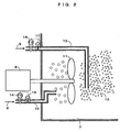
- FIG. 2 is an enlarged sectional view of a recirculation tank section of the wet flue-gas desulfurization system in FIG. 1 .
- FIG. 1 and FIG. 2 are sectional side views of a wet flue-gas desulfurization systems according to a concrete example of the present invention.
- FIG. 2 is an enlarged sectional view of a recirculation tank section of the wet flue-gas desulfurization system in FIG. 1 .
- the flue-gas desulfurization system is constructed mainly with an absorber shell 1, a gas inlet port 2, a gas outlet port 3, an absorbent liquid spray section 4, a spray nozzle 5, a recirculation pump 6, a recirculation tank section 7, an oxidation agitator 8, a posterior air pipe 10, a propeller 11, an anterior air pipe 13, a gypsum slurry bleed pipe 20, a gypsum dewatering system 21, and a mist eliminator section 30.
- a flue gas G of a boiler is introduced through the gas inlet port 2 and makes gas-liquid contact with an absorbent liquid sprayed from the spray nozzle 5 of the absorbent liquid spray section 4 to thereby become a clean gas, and is emitted through the gas outlet port 3 after accompanying mist is removed therefrom by the mist eliminator section 30. Moreover, the absorbent liquid brought in gas-liquid contact falls in the absorber shell 1 and is stored into the recirculation tank section 7.
- the absorbent liquid in the recirculation tank section 7 where gypsum exists as slurry is sent again to the spray nozzle 5 by the recirculation pump 6, is partly sent to the gypsum dewatering system 21 through the gypsum slurry bleed pipe 20, and is therein separated into solid gypsum and water.
- the posterior air pipe 10 can be arranged at a position which allows feeding air 9 within the range of a blade diameter of the propeller 11, while an outlet of the anterior air pipe 13 is preferably arranged at a position which allows feeding air 9 to a position slightly lower than being on a horizontal extended line of a central axis of rotation of the propeller 11 within the range of a blade diameter of the propeller 11.
- a constant amount of air is basically fed irrespective of a change in load of the boiler, while when the amount of air is changed with a change in boiler load, by changing the amount of air to be fed from the anterior air pipe 13 according to the boiler load while keeping the amount of air to be fed from the posterior air pipe 10 constant, the air 9 to be fed from the rear of a liquid discharge by the propeller 11 of the agitator 8 is atomized to fine bubbles by a shearing force resulting from a rotation of the propeller 11, and since this air 9 is constant, there is an effect that a constant air bubble dispersion distance and retention time in the recirculation tank section 7 can be maintained also for the air 9 to be fed to the front of a liquid discharge by the propeller 11.
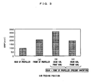
- Fig. 3 is a chart of comparison in the ORP (oxidation-reduction potential) value in an absorbent liquid, in terms of oxidation of calcium sulfate in flue-gas desulfurization systems with specifications shown in Table 1 that treat the same amount of SO 2 to be removed and control an airflow in each of the air pipes 10 and 13, between when the oxidation air 9 was fed from the rear of a liquid discharge by the propeller 11 and when being fed from the front of a liquid discharge by the propeller 11 in a conventional art and when being fed from the rear of a liquid discharge by the propeller 11 and when being fed from the front of a liquid discharge by the propeller 11 in the present invention.
- ORP oxidation-reduction potential
- ORP indicates an oxidation state of the absorbent liquid, and the higher the ORP value, the higher oxidation efficiency of calcium sulfite becomes.
- [Table 1] Amount of treated flue gas 600, 000 m 3 N/h Inlet SO 2 concentration 760 ppm Number of oxidizing agitators 3 Oxidation air feeding position Front and rear of propeller (Installation of air pipes at front and rear)
- the ratio of the amount of air to be fed to the rear and front of the propeller 11 is desirably made higher at the front than at the rear in the feeding ratio.
- the present invention has high industrial applicability as a wet flue-gas desulfurization system and method with which even when the amount of oxidation air to be fed to the recirculation tank section is increased, highly efficient oxidation can be performed without increasing the number of agitators installed and the operating cost.
Landscapes
- Engineering & Computer Science (AREA)
- Chemical & Material Sciences (AREA)
- Health & Medical Sciences (AREA)
- Biomedical Technology (AREA)
- Environmental & Geological Engineering (AREA)
- Analytical Chemistry (AREA)
- General Chemical & Material Sciences (AREA)
- Oil, Petroleum & Natural Gas (AREA)
- Chemical Kinetics & Catalysis (AREA)
- Treating Waste Gases (AREA)
- Gas Separation By Absorption (AREA)
Abstract
Description
- The present invention relates to a flue-gas desulfurization system and a recirculation tank section having a step of neutralizing/oxidizing a sulfur oxide (hereinafter, sometimes referred to as SO2) absorbed in an absorber recirculation tank section thereof, and particularly relates to a method for feeding oxidation air for oxidizing absorbed SO2.
- In recent years, the natural environment surrounding the earth has significantly deteriorated. Above all, in thermal power plants and the like located around the world, SO2 and soot and dust in flue gases generated as a result of combustion of fossil fuels are one of the main causes of environmental problems such as air pollution, and it has become mainstream to install a wet flue-gas desulfurization system for treatment of the flue gases.
- Particularly recently, reductions in the concentration of emission values of SO2 and soot and dust in flue gases have been demanded, while the inlet SO2 concentration has increased due to diversification of boiler fuels and the like, and thus there is a pressing need to develop a high-performance flue-gas desulfurization system.
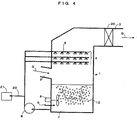
- An example of a flue-gas desulfurization system of a conventional art is shown in
FIG. 4 andFIG. 5 . The flue-gas desulfurization system is constructed mainly with anabsorber shell 1, agas inlet port 2, agas outlet port 3, an absorbentliquid spray section 4, aspray nozzle 5, arecirculation pump 6, arecirculation tank section 7, anoxidation agitator 8, aposterior air pipe 10, apropeller 11, a gypsum slurry bleedpipe 20, agypsum dewatering system 21, and amist eliminator section 30. - A flue gas G from a boiler is introduced through the
gas inlet port 2 and makes gas-liquid contact with an absorbent liquid sprayed from thespray nozzle 5 of the absorbentliquid spray section 4 to thereby become a clean gas, and is emitted through thegas outlet port 3 after accompanying mist is removed therefrom by themist eliminator section 30. - Moreover, the absorbent liquid brought in gas-liquid contact falls in the
absorber shell 1 and is stored into therecirculation tank section 7. In therecirculation tank section 7,air 9 to be fed is atomized into a large amount of fine bubbles by thepropeller 11 that rotates in conjunction with theoxidation agitator 8, and oxygen in the air dissolves in the absorbent liquid. In therecirculation tank section 7, calcium sulfite is produced by a neutralization reaction between absorbed SO2 and calcium carbonate that is fed to therecirculation tank section 7 by an unillustrated calcium carbonate feeding system, and the calcium sulfite is oxidized by oxygen dissolved in the absorbent liquid to produce gypsum. The absorbent liquid in therecirculation tank section 7 where gypsum exists as slurry is sent again to thespray nozzle 5 by therecirculation pump 6, is partly sent to thegypsum dewatering system 21 through the gypsum slurrybleed pipe 20, and is therein separated into solid gypsum and water. - In the abovementioned conventional art, the
oxidation air 9 is fed from theposterior air pipe 10 with a feed port, which is at the rear of thepropeller 11 of theagitator 8, to therecirculation tank section 7 as shown inFIG. 5 . This is a mode of increasing the air utilization rate by atomizing, by a shearing force generated by a rotation of thepropeller 11, theoxidation air 9 fed to therecirculation tank section 7 into a large amount of fine bubbles to thereby increase a gas-liquid contact area with the absorbent liquid (Japanese Published Unexamined Patent Application No.2001-120946 - Moreover, there is a method for feeding air to the front of the agitator propeller 11 (Japanese Published Unexamined Patent Application No.
H08-949 2000-317259 propeller 11 to thereby uniformly disperse air bubbles in the recirculation tank section while atomizing the same to fine bubbles. -
US 4239515 (A ) describes an apparatus for gas-liquid contact and separation by precipitation of solids therein, which essentially comprises a splash separating section, a solid-gas-liquid contact section and a solid depositing section formed in a single reaction vessel, in which gas is blown into the vessel through a gas disperser having a gas outlet opened below the liquid surface in said solid-gas-liquid contact section and caused to undergo contact with the phase of a suspension forcibly circulated from said solid depositing section formed below said solid-gas-liquid contact section, whereby the precipitated solids are prevented from depositing the inner surface of the vessel and other attendant members. -
US 5429808 (A ) describes an apparatus for wet process exhaust gas desulfurization including a spraying portion for spreading absorbent slurry, a plurality of stirrers for stirring each stirrer being an axial flow type agitator having a propeller, and a circular system for circulating the absorbent slurry from the slurry tank to the spraying portion. The apparatus further includes a plurality of nozzles for feeding oxidizer gas into the absorbent slurry from a backside of each propeller towards a periphery thereof uniformly with respect to a circumferential direction. - Of the abovementioned conventional arts, the mode of feeding the
oxidation air 9 from theposterior air pipe 10 with a feed port at the rear of thepropeller 11 of theagitator 8 to therecirculation tank section 7 shown inFIG. 5 may not sufficiently cope with a case where a flue gas with a high SO2 concentration is treated due to diversification of boiler fuels and the like in recent years. More specifically, when a flue gas with a high SO2 concentration is treated, the amount of calcium sulfite (Ca (HSO3)2) in the absorbent liquid increases, and therewith the amount of oxidation air to be fed also increases. However, there is a limit to the amount of oxidation air that can be fed per one agitator, and the amount of a discharge flow resulting from a rotation of thepropeller 11 is reduced when air of an amount larger than the limit value is fed, which results in a state of thepropeller 11 idly rotating in theair 9, so thatair bubbles 12 are not atomized to fine bubbles, the gas-liquid contact area with the absorbent liquid is reduced, and the oxidation efficiency is lowered. - Moreover, of the abovementioned conventional arts, the mode of feeding air into the absorbent liquid at the front of the
agitator propeller 11 allows uniformly dispersing oxidation air bubbles in therecirculation tank section 7 while atomizing the same to fine bubbles, however, since the air itself to be fed to the front of thepropeller 11 does not contact therotating propeller 11, the size of fine air bubbles is larger than that by the method for feeding air to the rear of thepropeller 11, and thus the contact area with the absorbent liquid is reduced, so that the oxidation efficiency is lowered. However, since the air itself to be fed to the front of thepropeller 11 is made to directly accompany a discharge flow generated by a rotation of thepropeller 11, there is an advantage that the air bubble dispersion distance in therecirculation tank section 7 is increased, the retention time is increased, and thus air bubbles are easily uniformly dispersed. - As described above, due to diversification of boiler fuels and the like in recent years, the amount of SO2 that should be removed has tended to increase in a flue gas, and therewith the amount of oxidation air has also increased. As there is a limit to the amount of oxidation air that can be fed per one
agitator 8, the amount of a discharge flow resulting from a rotation of thepropeller 11 is reduced when air of an amount larger than the limit is fed, which results in a state of thepropeller 11 idly rotating in the fedair 9, so thatair bubbles 12 are not atomized to fine bubbles, the gas-liquid contact area between theoxidation air bubbles 12 and the absorbent liquid is reduced, and the oxidation efficiency of SO2 is lowered. - Moreover, the
agitator 8 often performs, simultaneously with atomization of theoxidation air 9, agitation for preventing settlement of solids in an absorbent liquid slurry in therecirculation tank section 7, and if the amount of a discharge flow from thepropeller 11 is reduced by an increase in the amount of oxidation air, solids in the absorbent liquid slurry also settle at the bottom of therecirculation tank section 7, and this causes an inconvenience in operation of the plant, such as clogging of the pipes. - Therefore, conventionally, with an increase in the amount of oxidation air to be fed to the
recirculation tank section 7, the number ofagitators 8 installed has been increased, and this has caused an increase in the equipment cost and an increase in the maintenance cost of a user. Moreover, there are means for coping with an increase in the amount of oxidation air, with the same number ofagitators 8 installed, by increasing the diameter of the blades of thepropeller 11 or increasing the number of rotations of thepropeller 11, however, in both of these cases, power consumption, that is, the operating cost is increased by an increase in power of theagitator 8. - It is therefore an object of the present invention to provide a wet flue-gas desulfurization system and method with which even when the amount of oxidation air to be fed to the recirculation tank section is increased, highly efficient oxidation can be performed without increasing the number of agitators installed and the operating cost.
- The abovementioned obj ect can be achieved by the following solution means.
- A first aspect of the invention provides a wet flue-gas desulfurization system including: an absorber shell including a flue gas inlet port through which a flue gas containing a sulfur oxide and soot and dust emitted from a combustion system such as a boiler is introduced and an absorbent liquid spray section provided at a higher portion than the flue gas inlet port; and a recirculation tank section which stores an absorbent liquid that has absorbed a sulfur oxide in a flue gas and includes an agitator including a propeller to agitate the absorbent liquid, an air feeding means which injects oxidation air into a vicinity of the propeller, and an absorbent liquid circulating means which extracts the absorbent liquid from the recirculation tank after an oxidation reaction by air and a neutralization reaction by alkali and circulatively feeds the absorbent liquid to the absorbent liquid spray section of the absorber shell, wherein
the air feeding means is a means for feeding oxidation air to the absorbent liquid in the recirculation tank section at the rear and front of a liquid discharge by the propeller of the agitator,
wherein, on the air feeding means, provided is a means for adjusting a ratio of the amount of air to be fed to the rear and front of a liquid discharge by the propeller of the agitator. - Here, for the rear and front of a liquid discharge by the propeller, the front of a liquid discharge by the propeller denotes a direction in which the absorbent liquid in the recirculation tank section is discharged by a propeller for which the direction of a liquid discharge has been previously determined, and the rear of a liquid discharge by the propeller denotes a direction opposite the direction in which the absorbent liquid is discharged.
- A second aspect of the invention provides the wet flue-gas desulfurization system according to the first aspect, wherein an air injection port of the air feeding means to be installed at the front of a liquid discharge by the propeller of the agitator is arranged at a position lower than an extended line of a horizontal central axis of the propeller.
- A third aspect of the invention provides a method for wet flue-gas desulfurization in which a ratio of the amount of air to be fed, by use of the wet flue-gas desulfurization system according to the first or second aspects, to the rear and front of a liquid discharge by the propeller of the agitator, from the air feeding means that feeds oxidation air to the absorbent liquid in the recirculation tank section at the rear and front of a liquid discharge by the propeller of the agitator, is higher at the front of a liquid discharge than at the rear of a liquid discharge.
- A fourth aspect of the invention provides the method for wet flue-gas desulfurization according to the third aspect, wherein, of a required amount of air, a ratio of the amount of air to be fed to the rear and front of a liquid discharge by the propeller of the agitator is 10% at the rear of a liquid discharge and 90% at the front of a liquid discharge.
- A fifth aspect of the invention provides the method for wet flue-gas desulfurization according to the third aspect, wherein when the oxidation air to be fed to the air feeding means is changed in amount, of a required amount of air, an amount of air to be fed to the rear of a liquid discharge by the propeller of the agitator is kept constant, and an amount of air to be fed to the front of a liquid discharge by the propeller of the agitator is changed.
- In the present invention, by feeding oxidation air to the front of a liquid discharge (hereinafter, simply referred to as "front") and the rear of a liquid discharge (hereinafter, simply referred to as "rear") by the agitator propeller, air bubbles are atomized to fine bubbles by a shearing force generated by a rotation of the propeller for the air fed from the rear of the propeller, and the air fed from the front of the propeller is made to directly accompany a discharge flow generated by a rotation of the propeller to increase the air bubble dispersion distance, so that the retention time is increased. By thus making full use of both characteristics of feeding oxidation air to the front and rear of the agitator propeller, even when the amount of oxidation air is increased, oxidation efficiency can be improved without increasing the number of agitators installed.
- On the other hand, in Japanese Unexamined Patent Application No.
H05-317642 S59-13624 - In these conventional arts, most of the oxidation air does not receive an effect of a shearing force by an agitator and is thus not atomized to fine bubbles in comparison to the present invention, so that oxidation efficiency is deteriorated, and it is necessary to increase the power of an air blower by an increase in the amount of air and to increase the number of oxidation agitators installed.
- According to the first aspect of the invention, since air bubbles can be atomized to fine bubbles and the air bubbles can be uniformly dispersed in the recirculation tank section even when the amount of oxidation air is increased, it is possible to improve oxidation efficiency without increasing the number of agitators installed, and by adjusting the ratio of the amount of air to be fed to the rear and front of the propeller makes it possible to cope with a change in boiler load.
- According to the second aspect of the invention, in addition to the effect according to the first aspect of the invention, due to a characteristic that the liquid is discharged by a rotation of the propeller, a lower side of the propeller is faster in discharge flow speed and more easily forms a flow up to almost the center of the recirculation tank section, and thus the air bubbles are easily dispersed in the absorbent liquid of the recirculation tank section and the retention time is increased, and therefore, oxidation efficiency of SO2 in the absorbent liquid is improved.
- According to the third aspect of the invention, both effects of atomizing air to fine bubbles to be fed from the front of the propeller and an increase in the retention time improve oxidation efficiency of SO2 in the absorbent liquid.
- According to the forth aspect of the invention, in addition to the effect according to the third aspect of the invention, since the amount of air to be fed from the rear of the propeller is small, decline in the force of a liquid discharge by the propeller is slight, and thus the dispersion distance of the air bubbles made to accompany the liquid and the retention time in the recirculation tank section are reduced little, and therefore, oxidation efficiency of SO2 in the absorbent liquid is improved.
- According to the fifth aspect of the invention, in addition to the effect according to the third aspect of the invention, air to be fed from the rear of the propeller of the agitator is atomized to fine bubbles by a shearing force resulting from a rotation of the propeller, and since this air is constant, there is an effect that a constant air bubble dispersion distance and retention time in the recirculation tank section can be maintained also for air to be fed to the front of the propeller.
-
-
FIG. 1 is a sectional side view of a flue-gas desulfurization system of an example of the present invention. -
FIG. 2 is an enlarged sectional side view of a recirculation tank section of the flue-gas desulfurization system inFIG. 1 . -
FIG. 3 is a chart of comparison in the amount of air required for oxidation of calcium sulfite between desulfurization systems of the present invention and a conventional art. -
FIG. 4 is a sectional side view of a flue-gas desulfurization system of the conventional art. -
FIG. 5 is an enlarged sectional side view of a recirculation tank section of an embodiment of the conventional art. - Hereinafter, a concrete example of the present invention will be described by use of the drawings.
-
FIG. 1 is a sectional side view of a wet flue-gas desulfurization system according to a concrete example of the present invention.FIG. 2 is an enlarged sectional view of a recirculation tank section of the wet flue-gas desulfurization system inFIG. 1 . InFIG. 1 andFIG. 2 , the flue-gas desulfurization system is constructed mainly with anabsorber shell 1, agas inlet port 2, agas outlet port 3, an absorbentliquid spray section 4, aspray nozzle 5, arecirculation pump 6, arecirculation tank section 7, anoxidation agitator 8, aposterior air pipe 10, apropeller 11, ananterior air pipe 13, a gypsum slurry bleedpipe 20, agypsum dewatering system 21, and amist eliminator section 30. - A flue gas G of a boiler is introduced through the
gas inlet port 2 and makes gas-liquid contact with an absorbent liquid sprayed from thespray nozzle 5 of the absorbentliquid spray section 4 to thereby become a clean gas, and is emitted through thegas outlet port 3 after accompanying mist is removed therefrom by themist eliminator section 30. Moreover, the absorbent liquid brought in gas-liquid contact falls in theabsorber shell 1 and is stored into therecirculation tank section 7. - In the
recirculation tank section 7,air 9 that is fed by theposterior air pipe 10 and theanterior air pipe 13 is atomized into a large amount of fine bubbles by thepropeller 11 that rotates in conjunction with theoxidation agitator 8 to become air bubbles 12, and oxygen in the air bubbles 12 dissolves in the absorbent liquid. In therecirculation tank section 7, calcium sulfite is produced by a neutralization reaction between absorbed SO2 and calcium carbonate that is fed to therecirculation tank section 7 by an unillustrated calcium carbonate feeding system, and the calcium sulfite is oxidized by oxygen dissolved in the absorbent liquid to produce gypsum. The absorbent liquid in therecirculation tank section 7 where gypsum exists as slurry is sent again to thespray nozzle 5 by therecirculation pump 6, is partly sent to thegypsum dewatering system 21 through the gypsumslurry bleed pipe 20, and is therein separated into solid gypsum and water. - In such a structure, it suffices that the
posterior air pipe 10 can be arranged at a position which allows feedingair 9 within the range of a blade diameter of thepropeller 11, while an outlet of theanterior air pipe 13 is preferably arranged at a position which allows feedingair 9 to a position slightly lower than being on a horizontal extended line of a central axis of rotation of thepropeller 11 within the range of a blade diameter of thepropeller 11. This is because, due to a characteristic that the liquid is discharged by a rotation of thepropeller 11 of theagitator 8, a lower side of thepropeller 11 is faster in discharge flow speed and more easily forms a flow up to almost the center of therecirculation tank section 7, and thus the air bubbles 12 are easily dispersed in the absorbent liquid of therecirculation tank section 7 and the retention time is increased. - Moreover, with regard to the amount of air to be fed to the
recirculation tank section 7 from theposterior air pipe 10 and theanterior air pipe 13 as in the above, a constant amount of air is basically fed irrespective of a change in load of the boiler, while when the amount of air is changed with a change in boiler load, by changing the amount of air to be fed from theanterior air pipe 13 according to the boiler load while keeping the amount of air to be fed from theposterior air pipe 10 constant, theair 9 to be fed from the rear of a liquid discharge by thepropeller 11 of theagitator 8 is atomized to fine bubbles by a shearing force resulting from a rotation of thepropeller 11, and since thisair 9 is constant, there is an effect that a constant air bubble dispersion distance and retention time in therecirculation tank section 7 can be maintained also for theair 9 to be fed to the front of a liquid discharge by thepropeller 11. - Also, it is preferable to control the amount of air automatically by installing a
flowmeter 14 and aflow control valve 15 in theposterior air pipe 10 and further installing aflowmeter 16 and a flow control valve 17 also in theanterior air pipe 13. -
Fig. 3 is a chart of comparison in the ORP (oxidation-reduction potential) value in an absorbent liquid, in terms of oxidation of calcium sulfate in flue-gas desulfurization systems with specifications shown in Table 1 that treat the same amount of SO2 to be removed and control an airflow in each of theair pipes oxidation air 9 was fed from the rear of a liquid discharge by thepropeller 11 and when being fed from the front of a liquid discharge by thepropeller 11 in a conventional art and when being fed from the rear of a liquid discharge by thepropeller 11 and when being fed from the front of a liquid discharge by thepropeller 11 in the present invention. Here, ORP indicates an oxidation state of the absorbent liquid, and the higher the ORP value, the higher oxidation efficiency of calcium sulfite becomes.[Table 1] Amount of treated flue gas 600, 000 m3N/h Inlet SO2 concentration 760 ppm Number of oxidizing agitators 3 Oxidation air feeding position Front and rear of propeller (Installation of air pipes at front and rear) - In
FIG. 3 , when theoxidation air 9 was fed from the front of thepropeller 11 to the recirculation tank section 7 ((2) in the figure), the air bubbles 12 were made to directly accompany a discharge flow resulting from a rotation of thepropeller 11 so that the air bubble dispersion distance was increased and the retention time was increased, and thus in comparison with when theoxidation air 9 is fed to therecirculation tank section 7 from the rear of the propeller 11 ((1) in the figure) in the conventional art, the ORP value in the absorbent liquid was increased. In the method for feeding theoxidation air 9 to therecirculation tank section 7 of thepropeller 11 from the rear and front of thepropeller 11 of the present invention ((4) in the figure), when the same ratio was set for both the rear and front (50%:50%), in comparison with when theair 9 is fed only from the front of the propeller 11 ((2) in the figure), the ORP value in the absorbent liquid showed an almost equivalent result. - Moreover, a case where the ratio of the amount of air to be fed to the rear and front of the
propeller 11 was set at 10% for the rear and 90% for the front ((3) in the figure) showed the highest ORP value. This is because, as is when theair 9 was fed at the same ratio (50%: 50%) between the rear and front of the propeller 11 ((4) in the figure), if the ratio of the amount of air at the rear of thepropeller 11 is increased more than at the front, the amount of air retained in the periphery of therotating propeller 11 is increased, and as a result, the force of a liquid discharge by the rotatingpropeller 11 is lowered, and the dispersion distance of the air bubbles 12 made to accompany the liquid is reduced, whereby the retention time in therecirculation tank section 7 is reduced. - On the other hand, when the
air 9 was fed at a ratio of 90% to the front of thepropeller propeller 11 was small, the force of an absorbent liquid discharge by thepropeller 11 was slightly lowered, and thus the dispersion distance of the air bubbles 12 made to accompany the absorbent liquid and the retention time in therecirculation tank section 7 were not reduced. Moreover, theair 9 fed from the rear of thepropeller 11 was atomized to fine bubbles by a shearing force of therotating propeller 11 and theair 9 fed from the front of thepropeller 11 was made to directly accompany a discharge flow from the rotatingpropeller 11 and the dispersion distance was increased, so that the retention time was increased. It can be understood that the ORP value in the absorbent liquid becomes highest due to both effects of the atomization of theair 9 to be fed and increase in the retention time in therecirculation tank section 7. - For improving oxidation efficiency of SO2 in the absorbent liquid, the ratio of the amount of air to be fed to the rear and front of the
propeller 11 is desirably made higher at the front than at the rear in the feeding ratio. - The present invention has high industrial applicability as a wet flue-gas desulfurization system and method with which even when the amount of oxidation air to be fed to the recirculation tank section is increased, highly efficient oxidation can be performed without increasing the number of agitators installed and the operating cost.
Claims (5)
- A wet flue-gas desulfurization system comprising:an absorber shelf (1) including a flue gas inlet port (2) through which a flue gas containing a sulfur oxide and soot and dust emitted from a combustion system is introduced andan absorbent liquid spray section (4) provided at a higher portion than the flue gas inlet port; and
a recirculation tank section (7) which stores an absorbent liquid that has absorbed a sulfur oxide in a flue gas and includes an agitator (8) including a propeller (11) to agitate the absorbent liquid, an air feeding means (9) which blows oxidation air into a vicinity of the propeller (11), and an absorbent liquid recirculating mean (6) which extracts the absorbent liquid from the recirculation tank after an oxidation reaction by air and a neutralization reaction by alkali and recirculatively feeds the absorbent liquid to the absorbent liquid spray section (5) of the absorber shell, characterized in that
the air feeding means is a means for feeding oxidation air to the absorbent liquid in the recirculation tank section at the rear and front of a liquid discharge by the propeller of the agitator, and that
on the air feeding means is provided a means (14-17) for adjusting a ratio of the amount of air to be fed to the rear and front of a liquid discharge by the propeller of the agitator. - The wet flue-gas desulfurization system according to Claim 1, wherein an air injection port (13) of the air feeding means to be installed at the front of a liquid discharge by the propeller (11) of the agitator is arranged at a position lower than an extended line of a horizontal central axis of the propeller.
- A method for wet flue-gas desulfurization by use of the wet flue-gas desulfurization system according to Claim 1, wherein oxidation air to the absorbent liquid is fed in the recirculation tank section at the rear and front of a liquid discharge by the propeller of the agitator from the air feeding means and ratio of the amount of oxidation air to the rear and front of a liquid discharge by the propeller of the agitator is higher at the front of a liquid discharge than at the rear of a liquid discharge.
- The method for wet flue-gas desulfurization according to Claim 3, wherein, of a required amount of air, a ratio of the amount of air to be fed to the rear and front of a liquid discharge by the propeller of the agitator is 10% at the rear of a liquid discharge and 90% at the front of a liquid discharge.
- The method for wet flue-gas desulfurization according to Claim 3, wherein when the oxidation air to be fed to the air feeding means is changed in amount, of a required amount of air, an amount of air to be fed to the rear of a liquid discharge by the propeller of the agitator is kept constant, and an amount of air to be fed to the front of a liquid discharge by the propeller of the agitator is changed.
Priority Applications (1)
| Application Number | Priority Date | Filing Date | Title |
|---|---|---|---|
| PL06810295T PL1958682T3 (en) | 2005-12-07 | 2006-09-20 | Wet flue-gas desulfurization apparatus and method of wet flue-gas desulfurization |
Applications Claiming Priority (2)
| Application Number | Priority Date | Filing Date | Title |
|---|---|---|---|
| JP2005353164 | 2005-12-07 | ||
| PCT/JP2006/318595 WO2007066443A1 (en) | 2005-12-07 | 2006-09-20 | Wet flue-gas desulfurization apparatus and method of wet flue-gas desulfurization |
Publications (3)
| Publication Number | Publication Date |
|---|---|
| EP1958682A1 EP1958682A1 (en) | 2008-08-20 |
| EP1958682A4 EP1958682A4 (en) | 2010-03-24 |
| EP1958682B1 true EP1958682B1 (en) | 2011-04-13 |
Family
ID=38122595
Family Applications (1)
| Application Number | Title | Priority Date | Filing Date |
|---|---|---|---|
| EP06810295A Not-in-force EP1958682B1 (en) | 2005-12-07 | 2006-09-20 | Wet flue-gas desulfurization apparatus and method of wet flue-gas desulfurization |
Country Status (9)
| Country | Link |
|---|---|
| US (1) | US7731926B2 (en) |
| EP (1) | EP1958682B1 (en) |
| JP (1) | JP4776630B2 (en) |
| AU (1) | AU2006322822B2 (en) |
| CA (1) | CA2629766A1 (en) |
| DE (1) | DE602006021341D1 (en) |
| ES (1) | ES2360558T3 (en) |
| PL (1) | PL1958682T3 (en) |
| WO (1) | WO2007066443A1 (en) |
Cited By (1)
| Publication number | Priority date | Publication date | Assignee | Title |
|---|---|---|---|---|
| CN102658018A (en) * | 2012-05-11 | 2012-09-12 | 济南大学 | Rotary-net desulfurization dust remover |
Families Citing this family (20)
| Publication number | Priority date | Publication date | Assignee | Title |
|---|---|---|---|---|
| US8202482B2 (en) * | 2006-07-26 | 2012-06-19 | Babcock-Hitachi Kabushiki Kaisha | Apparatus for removing of trace of toxic substance from exhaust gas and method of operating the same |
| JP5046755B2 (en) * | 2007-06-27 | 2012-10-10 | 三菱重工業株式会社 | Gas-liquid contact device |
| CN101670228B (en) * | 2009-09-25 | 2011-07-27 | 东南大学 | Size pool mixing oxidation device |
| CN101816884A (en) * | 2010-04-22 | 2010-09-01 | 张保金 | Cooling method and equipment for use in chimney smoke desulphuration and dedusting |
| CN102091520B (en) * | 2010-12-28 | 2012-08-22 | 哈尔滨工业大学 | Wet desulphurization device and dust-fall processing method for circulation sizing based on wet desulphurization device |
| ES2392280B2 (en) | 2011-05-10 | 2013-06-10 | Universidad De Sevilla | CO2 AND SO2 CAPTURE PROCEDURE. |
| CN103055689B (en) * | 2013-01-09 | 2015-06-17 | 浙江大学 | Desulfurization absorption liquid capable of simultaneously stabilizing bivalent mercury |
| CN103480263A (en) * | 2013-10-17 | 2014-01-01 | 江苏欧超环保科技有限公司 | Pre-charge spraying desulfurization and dust removal device |
| CN104667719A (en) * | 2013-11-26 | 2015-06-03 | 上海交通大学 | Flue gas countercurrent direct-discharge-type purification method |
| US10375901B2 (en) | 2014-12-09 | 2019-08-13 | Mtd Products Inc | Blower/vacuum |
| US11065576B2 (en) | 2018-01-19 | 2021-07-20 | Doosan Heavy Industries & Construction Co., Ltd. | Wet flue gas desulfurization apparatus |
| KR102048538B1 (en) * | 2018-01-25 | 2019-11-25 | 두산중공업 주식회사 | Wet flue gas desulfurization apparatus |
| KR102048539B1 (en) * | 2018-01-19 | 2019-11-25 | 두산중공업 주식회사 | Wet flue gas desulfurization apparatus |
| CN110559816B (en) * | 2018-06-05 | 2021-10-08 | 中国石油化工股份有限公司 | Flue gas desulfurization tower and flue gas dedusting, desulfurization and wastewater treatment process |
| CN108905561A (en) * | 2018-06-20 | 2018-11-30 | 西昌宏鑫实业有限公司 | SO2 and dust flue gas controlling device and method in a kind of absorption boiler exhaust gas |
| CN112692026B (en) * | 2021-01-05 | 2023-06-13 | 江西依露得力医疗科技有限公司 | Waste gas absorption treatment device for anesthesia department |
| CN112958289A (en) * | 2021-02-05 | 2021-06-15 | 北京中科润宇环保科技股份有限公司 | Wet desulfurization sulfur flotation device and method |
| CN112791569A (en) * | 2021-03-09 | 2021-05-14 | 昆明理工大学 | Method for purifying acid gas by electrochemical synergistic microemulsion |
| CN114307573A (en) * | 2021-12-16 | 2022-04-12 | 徐州工业锅炉有限公司 | Flue gas emission processing apparatus in thermal power boiler |
| CN115888308B (en) * | 2023-01-07 | 2025-12-23 | 东莞市华志光电科技有限公司 | A water-mixed smoke gas impurity purification and separation system |
Family Cites Families (8)
| Publication number | Priority date | Publication date | Assignee | Title |
|---|---|---|---|---|
| JPS5915688B2 (en) * | 1976-08-10 | 1984-04-11 | 千代田化工建設株式会社 | Gas-liquid contact device |
| JPS5913624A (en) | 1982-07-14 | 1984-01-24 | ゼネラル・エレクトリツク・カンパニイ | By-production of gypsum simultaneously in single smoke exhaust desulfurization apparatus |
| JP2774519B2 (en) * | 1988-09-06 | 1998-07-09 | バブコツク日立株式会社 | Wet exhaust gas desulfurization equipment |
| JPH05317642A (en) * | 1992-05-14 | 1993-12-03 | Ishikawajima Harima Heavy Ind Co Ltd | Absorption tower of wet flue gas desulfurization equipment |
| JP3381389B2 (en) * | 1994-06-17 | 2003-02-24 | 石川島播磨重工業株式会社 | Gas injection device |
| JP3573950B2 (en) * | 1997-06-24 | 2004-10-06 | 東洋エンジニアリング株式会社 | Exhaust gas desulfurization method |
| JP2000317259A (en) | 1999-05-11 | 2000-11-21 | Ishikawajima Harima Heavy Ind Co Ltd | Flue gas desulfurization equipment |
| JP2001120946A (en) * | 1999-10-21 | 2001-05-08 | Babcock Hitachi Kk | Wet stack gas desulfurizing device and its operation method |
-
2006
- 2006-09-20 ES ES06810295T patent/ES2360558T3/en active Active
- 2006-09-20 AU AU2006322822A patent/AU2006322822B2/en not_active Ceased
- 2006-09-20 US US12/092,787 patent/US7731926B2/en active Active
- 2006-09-20 CA CA002629766A patent/CA2629766A1/en not_active Abandoned
- 2006-09-20 JP JP2007549025A patent/JP4776630B2/en not_active Expired - Fee Related
- 2006-09-20 DE DE602006021341T patent/DE602006021341D1/en active Active
- 2006-09-20 PL PL06810295T patent/PL1958682T3/en unknown
- 2006-09-20 EP EP06810295A patent/EP1958682B1/en not_active Not-in-force
- 2006-09-20 WO PCT/JP2006/318595 patent/WO2007066443A1/en not_active Ceased
Cited By (2)
| Publication number | Priority date | Publication date | Assignee | Title |
|---|---|---|---|---|
| CN102658018A (en) * | 2012-05-11 | 2012-09-12 | 济南大学 | Rotary-net desulfurization dust remover |
| CN102658018B (en) * | 2012-05-11 | 2014-03-12 | 济南大学 | Rotary-net desulfurization dust remover |
Also Published As
| Publication number | Publication date |
|---|---|
| CA2629766A1 (en) | 2007-06-14 |
| ES2360558T3 (en) | 2011-06-07 |
| WO2007066443A1 (en) | 2007-06-14 |
| PL1958682T3 (en) | 2011-07-29 |
| EP1958682A1 (en) | 2008-08-20 |
| JPWO2007066443A1 (en) | 2009-05-14 |
| JP4776630B2 (en) | 2011-09-21 |
| EP1958682A4 (en) | 2010-03-24 |
| US20090263305A1 (en) | 2009-10-22 |
| US7731926B2 (en) | 2010-06-08 |
| DE602006021341D1 (en) | 2011-05-26 |
| AU2006322822A1 (en) | 2007-06-14 |
| AU2006322822B2 (en) | 2010-07-15 |
Similar Documents
| Publication | Publication Date | Title |
|---|---|---|
| AU2006322822B2 (en) | Wet flue-gas desulfurization apparatus and method of wet flue-gas desulfurization | |
| CN1083290C (en) | Wet type exhaust gas desulfurization method and apparatus utilizing solid desulfurizing agent | |
| EP1243308B1 (en) | Apparatus for wet type flue-gas desulfurization | |
| DK174985B1 (en) | Flue gas desulphurisation apparatus for wet treatment | |
| CN108636092B (en) | Flue gas desulfurization and denitrification system and method | |
| US11065576B2 (en) | Wet flue gas desulfurization apparatus | |
| CN105169926A (en) | Flue gas desulphurization system and method for flue gas desulfurization by means of same | |
| KR100285102B1 (en) | Oxygen-containing gas blower of wet flue gas desulfurizer and flue gas desulfurizer | |
| CN105233659B (en) | A kind of fume desulfurizing tower and fume desulphurization method | |
| CN206881495U (en) | Remove the device of sulfur dioxide in flue gas and mercury | |
| CN208553730U (en) | A kind of flue gas desulfurization and denitrification system | |
| JP3392635B2 (en) | Exhaust gas treatment method and device | |
| CN217410334U (en) | Carbon calcining furnace flue gas treatment system | |
| JP3910307B2 (en) | Wet flue gas desulfurization equipment | |
| CN211098394U (en) | Wet desulphurization system for controlling pH value of spraying slurry | |
| CN210448716U (en) | High-efficiency pneumatic emulsification dust removal and desulfurization device for flue gas | |
| JP3068452B2 (en) | Wet flue gas desulfurization equipment | |
| CN1266046C (en) | Forced oxidizing method and its device for smoke desulfurizing intermediate product-calcium sulfite | |
| KR20210079839A (en) | Impeller of pump for desulfurization equipment | |
| JPH08215532A (en) | Gas absorber | |
| KR0135324B1 (en) | Air supply stirring device for flue gas desulfurization process | |
| CN113274870A (en) | Carbon calcining furnace flue gas treatment method and system | |
| JPH02111420A (en) | Stack gas desulfurizing device of wet system | |
| CN118142321A (en) | Flue gas desulfurization tower and flue gas desulfurization process | |
| JPH0686912A (en) | Wet-type flue gas desulfurization facility |
Legal Events
| Date | Code | Title | Description |
|---|---|---|---|
| PUAI | Public reference made under article 153(3) epc to a published international application that has entered the european phase |
Free format text: ORIGINAL CODE: 0009012 |
|
| 17P | Request for examination filed |
Effective date: 20080514 |
|
| AK | Designated contracting states |
Kind code of ref document: A1 Designated state(s): AT BE BG CH CY CZ DE DK EE ES FI FR GB GR HU IE IS IT LI LT LU LV MC NL PL PT RO SE SI SK TR |
|
| A4 | Supplementary search report drawn up and despatched |
Effective date: 20100224 |
|
| 17Q | First examination report despatched |
Effective date: 20100526 |
|
| RIC1 | Information provided on ipc code assigned before grant |
Ipc: B01D 53/77 20060101ALI20100721BHEP Ipc: B01D 53/50 20060101AFI20100721BHEP Ipc: B01D 53/18 20060101ALI20100721BHEP |
|
| GRAP | Despatch of communication of intention to grant a patent |
Free format text: ORIGINAL CODE: EPIDOSNIGR1 |
|
| DAX | Request for extension of the european patent (deleted) | ||
| GRAS | Grant fee paid |
Free format text: ORIGINAL CODE: EPIDOSNIGR3 |
|
| GRAA | (expected) grant |
Free format text: ORIGINAL CODE: 0009210 |
|
| AK | Designated contracting states |
Kind code of ref document: B1 Designated state(s): AT BE BG CH CY CZ DE DK EE ES FI FR GB GR HU IE IS IT LI LT LU LV MC NL PL PT RO SE SI SK TR |
|
| REG | Reference to a national code |
Ref country code: GB Ref legal event code: FG4D |
|
| REG | Reference to a national code |
Ref country code: CH Ref legal event code: EP |
|
| REG | Reference to a national code |
Ref country code: IE Ref legal event code: FG4D |
|
| REF | Corresponds to: |
Ref document number: 602006021341 Country of ref document: DE Date of ref document: 20110526 Kind code of ref document: P |
|
| REG | Reference to a national code |
Ref country code: DE Ref legal event code: R096 Ref document number: 602006021341 Country of ref document: DE Effective date: 20110526 |
|
| REG | Reference to a national code |
Ref country code: ES Ref legal event code: FG2A Ref document number: 2360558 Country of ref document: ES Kind code of ref document: T3 Effective date: 20110607 |
|
| REG | Reference to a national code |
Ref country code: NL Ref legal event code: VDEP Effective date: 20110413 |
|
| REG | Reference to a national code |
Ref country code: PL Ref legal event code: T3 |
|
| LTIE | Lt: invalidation of european patent or patent extension |
Effective date: 20110413 |
|
| PG25 | Lapsed in a contracting state [announced via postgrant information from national office to epo] |
Ref country code: SE Free format text: LAPSE BECAUSE OF FAILURE TO SUBMIT A TRANSLATION OF THE DESCRIPTION OR TO PAY THE FEE WITHIN THE PRESCRIBED TIME-LIMIT Effective date: 20110413 Ref country code: PT Free format text: LAPSE BECAUSE OF FAILURE TO SUBMIT A TRANSLATION OF THE DESCRIPTION OR TO PAY THE FEE WITHIN THE PRESCRIBED TIME-LIMIT Effective date: 20110816 Ref country code: LT Free format text: LAPSE BECAUSE OF FAILURE TO SUBMIT A TRANSLATION OF THE DESCRIPTION OR TO PAY THE FEE WITHIN THE PRESCRIBED TIME-LIMIT Effective date: 20110413 |
|
| PG25 | Lapsed in a contracting state [announced via postgrant information from national office to epo] |
Ref country code: BE Free format text: LAPSE BECAUSE OF FAILURE TO SUBMIT A TRANSLATION OF THE DESCRIPTION OR TO PAY THE FEE WITHIN THE PRESCRIBED TIME-LIMIT Effective date: 20110413 Ref country code: LV Free format text: LAPSE BECAUSE OF FAILURE TO SUBMIT A TRANSLATION OF THE DESCRIPTION OR TO PAY THE FEE WITHIN THE PRESCRIBED TIME-LIMIT Effective date: 20110413 Ref country code: CY Free format text: LAPSE BECAUSE OF FAILURE TO SUBMIT A TRANSLATION OF THE DESCRIPTION OR TO PAY THE FEE WITHIN THE PRESCRIBED TIME-LIMIT Effective date: 20110413 Ref country code: GR Free format text: LAPSE BECAUSE OF FAILURE TO SUBMIT A TRANSLATION OF THE DESCRIPTION OR TO PAY THE FEE WITHIN THE PRESCRIBED TIME-LIMIT Effective date: 20110714 Ref country code: FI Free format text: LAPSE BECAUSE OF FAILURE TO SUBMIT A TRANSLATION OF THE DESCRIPTION OR TO PAY THE FEE WITHIN THE PRESCRIBED TIME-LIMIT Effective date: 20110413 Ref country code: SI Free format text: LAPSE BECAUSE OF FAILURE TO SUBMIT A TRANSLATION OF THE DESCRIPTION OR TO PAY THE FEE WITHIN THE PRESCRIBED TIME-LIMIT Effective date: 20110413 Ref country code: AT Free format text: LAPSE BECAUSE OF FAILURE TO SUBMIT A TRANSLATION OF THE DESCRIPTION OR TO PAY THE FEE WITHIN THE PRESCRIBED TIME-LIMIT Effective date: 20110413 Ref country code: IS Free format text: LAPSE BECAUSE OF FAILURE TO SUBMIT A TRANSLATION OF THE DESCRIPTION OR TO PAY THE FEE WITHIN THE PRESCRIBED TIME-LIMIT Effective date: 20110813 |
|
| PG25 | Lapsed in a contracting state [announced via postgrant information from national office to epo] |
Ref country code: NL Free format text: LAPSE BECAUSE OF FAILURE TO SUBMIT A TRANSLATION OF THE DESCRIPTION OR TO PAY THE FEE WITHIN THE PRESCRIBED TIME-LIMIT Effective date: 20110413 |
|
| PG25 | Lapsed in a contracting state [announced via postgrant information from national office to epo] |
Ref country code: EE Free format text: LAPSE BECAUSE OF FAILURE TO SUBMIT A TRANSLATION OF THE DESCRIPTION OR TO PAY THE FEE WITHIN THE PRESCRIBED TIME-LIMIT Effective date: 20110413 |
|
| PLBE | No opposition filed within time limit |
Free format text: ORIGINAL CODE: 0009261 |
|
| STAA | Information on the status of an ep patent application or granted ep patent |
Free format text: STATUS: NO OPPOSITION FILED WITHIN TIME LIMIT |
|
| PG25 | Lapsed in a contracting state [announced via postgrant information from national office to epo] |
Ref country code: RO Free format text: LAPSE BECAUSE OF FAILURE TO SUBMIT A TRANSLATION OF THE DESCRIPTION OR TO PAY THE FEE WITHIN THE PRESCRIBED TIME-LIMIT Effective date: 20110413 Ref country code: SK Free format text: LAPSE BECAUSE OF FAILURE TO SUBMIT A TRANSLATION OF THE DESCRIPTION OR TO PAY THE FEE WITHIN THE PRESCRIBED TIME-LIMIT Effective date: 20110413 Ref country code: DK Free format text: LAPSE BECAUSE OF FAILURE TO SUBMIT A TRANSLATION OF THE DESCRIPTION OR TO PAY THE FEE WITHIN THE PRESCRIBED TIME-LIMIT Effective date: 20110413 |
|
| 26N | No opposition filed |
Effective date: 20120116 |
|
| PG25 | Lapsed in a contracting state [announced via postgrant information from national office to epo] |
Ref country code: MC Free format text: LAPSE BECAUSE OF NON-PAYMENT OF DUE FEES Effective date: 20110930 |
|
| REG | Reference to a national code |
Ref country code: CH Ref legal event code: PL |
|
| REG | Reference to a national code |
Ref country code: DE Ref legal event code: R097 Ref document number: 602006021341 Country of ref document: DE Effective date: 20120116 |
|
| GBPC | Gb: european patent ceased through non-payment of renewal fee |
Effective date: 20110920 |
|
| PG25 | Lapsed in a contracting state [announced via postgrant information from national office to epo] |
Ref country code: IT Free format text: LAPSE BECAUSE OF FAILURE TO SUBMIT A TRANSLATION OF THE DESCRIPTION OR TO PAY THE FEE WITHIN THE PRESCRIBED TIME-LIMIT Effective date: 20110413 |
|
| REG | Reference to a national code |
Ref country code: IE Ref legal event code: MM4A |
|
| REG | Reference to a national code |
Ref country code: FR Ref legal event code: ST Effective date: 20120531 |
|
| PG25 | Lapsed in a contracting state [announced via postgrant information from national office to epo] |
Ref country code: IE Free format text: LAPSE BECAUSE OF NON-PAYMENT OF DUE FEES Effective date: 20110920 Ref country code: CH Free format text: LAPSE BECAUSE OF NON-PAYMENT OF DUE FEES Effective date: 20110930 Ref country code: LI Free format text: LAPSE BECAUSE OF NON-PAYMENT OF DUE FEES Effective date: 20110930 |
|
| PG25 | Lapsed in a contracting state [announced via postgrant information from national office to epo] |
Ref country code: GB Free format text: LAPSE BECAUSE OF NON-PAYMENT OF DUE FEES Effective date: 20110920 Ref country code: FR Free format text: LAPSE BECAUSE OF NON-PAYMENT OF DUE FEES Effective date: 20110930 |
|
| PG25 | Lapsed in a contracting state [announced via postgrant information from national office to epo] |
Ref country code: LU Free format text: LAPSE BECAUSE OF NON-PAYMENT OF DUE FEES Effective date: 20110920 |
|
| PG25 | Lapsed in a contracting state [announced via postgrant information from national office to epo] |
Ref country code: BG Free format text: LAPSE BECAUSE OF FAILURE TO SUBMIT A TRANSLATION OF THE DESCRIPTION OR TO PAY THE FEE WITHIN THE PRESCRIBED TIME-LIMIT Effective date: 20110713 |
|
| PG25 | Lapsed in a contracting state [announced via postgrant information from national office to epo] |
Ref country code: TR Free format text: LAPSE BECAUSE OF FAILURE TO SUBMIT A TRANSLATION OF THE DESCRIPTION OR TO PAY THE FEE WITHIN THE PRESCRIBED TIME-LIMIT Effective date: 20110413 |
|
| PG25 | Lapsed in a contracting state [announced via postgrant information from national office to epo] |
Ref country code: HU Free format text: LAPSE BECAUSE OF FAILURE TO SUBMIT A TRANSLATION OF THE DESCRIPTION OR TO PAY THE FEE WITHIN THE PRESCRIBED TIME-LIMIT Effective date: 20110413 |
|
| REG | Reference to a national code |
Ref country code: DE Ref legal event code: R082 Ref document number: 602006021341 Country of ref document: DE Representative=s name: TBK, DE |
|
| REG | Reference to a national code |
Ref country code: DE Ref legal event code: R081 Ref document number: 602006021341 Country of ref document: DE Owner name: MITSUBISHI HITACHI POWER SYSTEMS, LTD., YOKOHA, JP Free format text: FORMER OWNER: BABCOCK-HITACHI K.K., TOKIO/TOKYO, JP Effective date: 20150305 Ref country code: DE Ref legal event code: R082 Ref document number: 602006021341 Country of ref document: DE Representative=s name: TBK, DE Effective date: 20150305 |
|
| REG | Reference to a national code |
Ref country code: ES Ref legal event code: PC2A Owner name: MITSUBISHI HITACHI POWER SYSTEMS, LTD. Effective date: 20150421 |
|
| REG | Reference to a national code |
Ref country code: DE Ref legal event code: R082 Ref document number: 602006021341 Country of ref document: DE Representative=s name: TBK, DE Ref country code: DE Ref legal event code: R081 Ref document number: 602006021341 Country of ref document: DE Owner name: MITSUBISHI POWER, LTD., JP Free format text: FORMER OWNER: MITSUBISHI HITACHI POWER SYSTEMS, LTD., YOKOHAMA, KANAGAWA, JP |
|
| REG | Reference to a national code |
Ref country code: ES Ref legal event code: PC2A Owner name: MITSUBISHI POWER, LTD. Effective date: 20210421 |
|
| PGFP | Annual fee paid to national office [announced via postgrant information from national office to epo] |
Ref country code: CZ Payment date: 20210826 Year of fee payment: 16 |
|
| PGFP | Annual fee paid to national office [announced via postgrant information from national office to epo] |
Ref country code: PL Payment date: 20210813 Year of fee payment: 16 Ref country code: DE Payment date: 20210810 Year of fee payment: 16 |
|
| PGFP | Annual fee paid to national office [announced via postgrant information from national office to epo] |
Ref country code: ES Payment date: 20211001 Year of fee payment: 16 |
|
| REG | Reference to a national code |
Ref country code: DE Ref legal event code: R119 Ref document number: 602006021341 Country of ref document: DE |
|
| PG25 | Lapsed in a contracting state [announced via postgrant information from national office to epo] |
Ref country code: CZ Free format text: LAPSE BECAUSE OF NON-PAYMENT OF DUE FEES Effective date: 20220920 |
|
| PG25 | Lapsed in a contracting state [announced via postgrant information from national office to epo] |
Ref country code: DE Free format text: LAPSE BECAUSE OF NON-PAYMENT OF DUE FEES Effective date: 20230401 |
|
| REG | Reference to a national code |
Ref country code: ES Ref legal event code: FD2A Effective date: 20231027 |
|
| PG25 | Lapsed in a contracting state [announced via postgrant information from national office to epo] |
Ref country code: ES Free format text: LAPSE BECAUSE OF NON-PAYMENT OF DUE FEES Effective date: 20220921 |
|
| PG25 | Lapsed in a contracting state [announced via postgrant information from national office to epo] |
Ref country code: ES Free format text: LAPSE BECAUSE OF NON-PAYMENT OF DUE FEES Effective date: 20220921 |
|
| PG25 | Lapsed in a contracting state [announced via postgrant information from national office to epo] |
Ref country code: PL Free format text: LAPSE BECAUSE OF NON-PAYMENT OF DUE FEES Effective date: 20220920 |