EP1958219B1 - Wiring apparatus - Google Patents
Wiring apparatus Download PDFInfo
- Publication number
- EP1958219B1 EP1958219B1 EP06832479.7A EP06832479A EP1958219B1 EP 1958219 B1 EP1958219 B1 EP 1958219B1 EP 06832479 A EP06832479 A EP 06832479A EP 1958219 B1 EP1958219 B1 EP 1958219B1
- Authority
- EP
- European Patent Office
- Prior art keywords
- wires
- nozzles
- nozzle
- bobbin
- winding
- Prior art date
- Legal status (The legal status is an assumption and is not a legal conclusion. Google has not performed a legal analysis and makes no representation as to the accuracy of the status listed.)
- Ceased
Links
- 238000004804 winding Methods 0.000 claims description 51
- 238000000034 method Methods 0.000 description 10
- 238000004519 manufacturing process Methods 0.000 description 4
- 239000004734 Polyphenylene sulfide Substances 0.000 description 2
- 238000001514 detection method Methods 0.000 description 2
- 238000010586 diagram Methods 0.000 description 2
- 229920000069 polyphenylene sulfide Polymers 0.000 description 2
- RYGMFSIKBFXOCR-UHFFFAOYSA-N Copper Chemical compound [Cu] RYGMFSIKBFXOCR-UHFFFAOYSA-N 0.000 description 1
- 210000003298 dental enamel Anatomy 0.000 description 1
- 230000000717 retained effect Effects 0.000 description 1
- 229920003002 synthetic resin Polymers 0.000 description 1
- 239000000057 synthetic resin Substances 0.000 description 1
Images




Classifications
-
- H—ELECTRICITY
- H01—ELECTRIC ELEMENTS
- H01F—MAGNETS; INDUCTANCES; TRANSFORMERS; SELECTION OF MATERIALS FOR THEIR MAGNETIC PROPERTIES
- H01F41/00—Apparatus or processes specially adapted for manufacturing or assembling magnets, inductances or transformers; Apparatus or processes specially adapted for manufacturing materials characterised by their magnetic properties
- H01F41/02—Apparatus or processes specially adapted for manufacturing or assembling magnets, inductances or transformers; Apparatus or processes specially adapted for manufacturing materials characterised by their magnetic properties for manufacturing cores, coils, or magnets
- H01F41/04—Apparatus or processes specially adapted for manufacturing or assembling magnets, inductances or transformers; Apparatus or processes specially adapted for manufacturing materials characterised by their magnetic properties for manufacturing cores, coils, or magnets for manufacturing coils
- H01F41/06—Coil winding
- H01F41/082—Devices for guiding or positioning the winding material on the former
-
- H—ELECTRICITY
- H01—ELECTRIC ELEMENTS
- H01F—MAGNETS; INDUCTANCES; TRANSFORMERS; SELECTION OF MATERIALS FOR THEIR MAGNETIC PROPERTIES
- H01F41/00—Apparatus or processes specially adapted for manufacturing or assembling magnets, inductances or transformers; Apparatus or processes specially adapted for manufacturing materials characterised by their magnetic properties
- H01F41/02—Apparatus or processes specially adapted for manufacturing or assembling magnets, inductances or transformers; Apparatus or processes specially adapted for manufacturing materials characterised by their magnetic properties for manufacturing cores, coils, or magnets
- H01F41/04—Apparatus or processes specially adapted for manufacturing or assembling magnets, inductances or transformers; Apparatus or processes specially adapted for manufacturing materials characterised by their magnetic properties for manufacturing cores, coils, or magnets for manufacturing coils
- H01F41/06—Coil winding
- H01F41/096—Dispensing or feeding devices
-
- H—ELECTRICITY
- H02—GENERATION; CONVERSION OR DISTRIBUTION OF ELECTRIC POWER
- H02K—DYNAMO-ELECTRIC MACHINES
- H02K7/00—Arrangements for handling mechanical energy structurally associated with dynamo-electric machines, e.g. structural association with mechanical driving motors or auxiliary dynamo-electric machines
- H02K7/10—Structural association with clutches, brakes, gears, pulleys or mechanical starters
- H02K7/116—Structural association with clutches, brakes, gears, pulleys or mechanical starters with gears
Definitions
- the present invention relates to an apparatus for regularly winding a plurality of wires on a bobbin to manufacture a coil.
- the publication '922 discloses a winding apparatus structured to include two or three rotatable nozzles through which wires are supplied and to manufacture both a multilayered coil and a parallel coil. Those two or three nozzles are retained by a rotatable nozzle holder. When a bobbin is rotated while the wires are unreeled to be supplied through the nozzles, the wires are wound on the bobbin.
- the nozzle holder In synchronism with the rotation of the bobbin, the nozzle holder is rotated to rotate the two or three nozzles about a predetermined rotation center, thereby winding the two or three wires together in multilayered or parallel relation on the periphery of the bobbin.
- JP 02 262861 A aims to prevent coil wires from getting entangled by rotating a coil wire supply port for supplying a plurality of coil wires installed to a rotating body, which rotates round a pole piece on the inner face of a cylindrical yoke, synchronously with the rotation of the rotating body.
- a plurality of (five in the figure) coil wires are wound round a pole core installed on the inner face of a cylindrical yoke.
- the coil wires are supplied from the coil supply part of the nozzle of a nozzle body which rotates round the pole core.
- the coil supply port is rotated o the center of the nozzle body synchronously with the rotation of the nozzle body round the pole core. Thereby entanglement of the coil wires is prevented to decrease the space occupying factor of the coil wires.
- the publication '922 discloses the winding apparatus structured to simultaneously wind two or three wires; however, it has no disclosure or suggestion about a technique of simultaneously winding more than three wires.
- productivity of coils it is preferable that three or more wires are simultaneously wound on a bobbin.
- miniaturization of coils additionally, it is preferable that a single apparatus can provide various winding methods or patterns.
- the present invention has been made in view of the above circumstances and has an object to provide a winding apparatus capable of simultaneously winding three or more wires and providing various winding methods.
- the present invention according to one aspect provides a winding apparatus as defined in appended claim 1.
- the first rotation means and the second rotation means are separately controlled. It is therefore possible to change the rotation angles of the nozzle holder and the multiple-wire nozzle respectively, thereby changing the position of the wire supplied through each nozzle relative to the bobbin.
- the plurality of nozzles is all the multiple-wire nozzles, and each multiple-wire nozzle includes the second rotation means.
- the first rotation means and the second rotation means are separately controlled. It is therefore possible to change the rotation angles of the nozzle holder and the plurality of the multiple-wire nozzles respectively, thereby changing the positions of the wires supplied through the plurality of the multiple-wire nozzles relative to the bobbin.
- the multiple-wire nozzles are provided two, each of which is configured to allow two wires to pass therethrough.
- the first rotation means and the second rotation means are separately controlled. It is therefore possible to change the rotation angles of the nozzle holder and the two multiple-wire nozzles respectively, thereby changing the positions of a pair of two wires and another pair of two wired unreeled to be supplied to the bobbin through the two nozzles relative to the bobbin.
- the present embodiment exemplifies a winding apparatus for manufacturing a rectangular coil unit by simultaneously regularly winding four wires on a bobbin.
- Fig. 5 is a perspective view of a rectangular coil unit 1 in the present embodiment.
- Fig. 6 is a back view of the rectangular coil unit 1.
- Fig. 7 is a front view of the rectangular coil unit 1 from which a first flange is removed for convenience of explanation.
- the rectangular coil unit 1 in the present embodiment is manufactured in such a manner that four wires 2 are simultaneously regularly wound on four outer surfaces of a bobbin 3 having a rectangular section.
- a plurality of such rectangular coil units 1 will be mounted in a plurality of teeth formed on the inner periphery of a stator core, thus constituting a stator.
- This stator is further assembled with a rotor, producing a motor.
- the bobbin 3 includes a core tube 3a of a rectangular section, a first flange 3b and a second flange 3c formed at both axial ends of the core tube 3a.
- the bobbin 3 is made of a synthetic resin such as PPS (polyphenylene sulfide) to have an insulating property.
- the first flange 3b provided on a rear side has a distinctive shape as compared with the second flange 3c provided on a front side having a nearly normal rectangular shape.
- the first flange 3b includes upper and lower cutout portions 3d and 3e, an insulating wall 3f protruding from one of side surfaces of the upper cutout portion 3d in Fig.
- the core tube 3a is hollow, providing a center hole 3h. A clearance is formed between the insulating wall 3f and a lower surface of the upper cutout portion 3d as shown in Fig. 6 .
- Onto the core tube 3a four wires 2 are simultaneously regularly wound, forming a coil 4 having a hollow rectangular shape. Both end portions of each of four wires 2 are partly engaged with the insulating wall 3f and the stopper groove 3g.
- a relatively thick wire 2 is used to achieve a small-sized high-power motor.
- the wire 2 is made of a copper wire coated with an enamel insulating film.
- the four wires 2 are wound regularly and reciprocally in opposite directions along the axis of the core tube 3a as above, forming the coil 4 with a plurality of rows and a plurality of layers of wires. After winding, the end portions of the two wires 2 are engaged in the stopper groove 3g.
- the rectangular coil unit 1 including the coil 4 formed in the above manner to have a rectangular section is thus manufactured.
- Fig. 8 is a side view of the coil 4 on the bobbin 3.
- Fig. 9 is a back view of the coil 4 on the bobbin 3.
- Figs. 10A to 10D are views seen from directions indicated by arrows A, B, C, and D in Fig. 8 respectively.
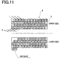
- Fig. 11 is a pattern diagram showing the arrangement of the coil 4 on the bobbin 3. As shown in Figs. 8 to 11 , in the present embodiment, the four wires 2 are wound in such a manner as to advance obliquely together for a lane change corresponding to 2 wires (i.e.
- the above lane changes are repeated as in the above manner on the upper side and the lower side.
- the first layer of the coil 4 is thus formed (the first layer has 3 turns as indicated by numbers “1" to "3" in Figs. 10A and 10B .).
- the wires 2 are turned (folded) back at an opposite position from the winding start position.
- the 2-wire lane change is performed in a direction opposite to that for the first layer as shown in Fig. 10B .
- the 2-wire lane change is performed in the direction opposite to that the first layer as shown in Fig. 10A .
- the four wires 2 are twisted 90° at the turn-back of the winding operation and hence the wires 2 intersect to overlap each other as shown in Fig. 10D as a shaded area shown in Fig. 10B .
- Fig. 11 when the winding is completed at the end of the bobbin 3, two of the four wires 2 are left uncoiled in that winding end position.
- FIG. 1 shows a schematic configuration view of a winding apparatus 11.
- This winding apparatus 11 comprises two nozzles (first nozzle 12 and second nozzle 13), each of which is configured to allow two wires 2 to pass therethrough to be supplied to the bobbin 3, and a columnar nozzle holder 14 holding the two nozzles 12 and 13 in parallel.
- the winding apparatus 11 is structured to supply a total of four wires 2 through the two nozzles 12 and 13 and wind them on the bobbin 3 to form the coil 4.
- the axes of the nozzles 12 and 13 and the axis of the nozzle holder 14 are substantially parallel to each other.
- the nozzles 12 and 13 are held in and through the nozzle holder 14 so as to be rotatable relative to the nozzle holder 14.
- the wires 2 to be supplied through the nozzles 12 and 13 are unreeled from separate wire drums 15 respectively.
- the first and second nozzles 12 and 13 correspond to a multiple-wire nozzle of the present invention.
- the nozzle holder 14 is integrally provided on its outer periphery with a driven gear 14a engaging with a drive gear 16 attached to an output shaft 21a of the first motor 21.
- Driving the first motor 21 causes the nozzle holder 14, via the drive gear 16 and the driven gear 14a, to rotate about its own axis substantially parallel to the nozzles 12 and 13.
- the driven gear 14a, the drive gear 16, and the first motor 21 constitute first rotation means of the present invention.
- a rotation angle HA of the nozzle holder 14 is detected by a fist rotation angle sensor 31.
- driven gears 12a and 13a are integrally provided respectively. Those driven gears 12a and 13a are coupled to drive gears 17 and 18 attached to an output shaft 22a of a second motor 22 and an output shaft 23a of a third motor 23 respectively.
- Driving the second motor 22 causes the first nozzle 12, via the drive gear 17 and the driven gear 12a, to rotate about its own axis.
- driving the third motor 23 causes the second nozzle 13, via the drive gear 18 and the driven gear 13a, to rotate about its own axis.
- the driven gears 12a and 13a, the drive gears 17 and 18, the second motor 22, and the third motor 23 constitute second rotation means of the present invention.
- a rotation angle N1A of the first nozzle 12 is detected by a second rotation angle sensor 32.
- a rotation angle N2A of the second nozzle 13 is detected by a third rotation angle sensor 33.
- Fig. 2 is a perspective view showing a schematic configuration of the nozzle holder 14 and the nozzles 12 and 13.
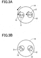
- Figs. 3A and 3B are plan views showing the front end of the nozzle holder 14.
- the nozzle holder 14, nozzles 12 and 13 are independently rotatable.
- the arrangement of the two nozzles 12 and 13 can be changed.
- the two nozzles 12 and 13 may be arranged in horizontal relation as shown in Figs. 3A and 3B or in vertical or oblique relation.
- Rotation of each nozzle 12 and 13 further enables changes in the arrangement of two wires 2.
- two wires 2 may be arranged in horizontal relation as shown in Fig. 3A , in vertical relation, or in oblique relation as shown in Fig. 3B .
- the bobbin 3 is removably fitted on a movable shaft 19a of a bobbin holder 19 as shown Fig. 1 .
- This movable shaft 19a is configured to rotate the bobbin 3 about the axis of the shaft 19a and slide the bobbin 3 along the axis thereof.
- the bobbin holder 19 includes a fourth motor 4 and a rotation mechanism (not shown) for rotating the movable shaft 19a to rotate the bobbin 3, and a fifth motor 25 and a slide mechanism (not shown) for sliding the movable shaft 19a to slide the bobbin 3.
- a rotation angle of the bobbin 3 is detected by a fourth rotation angle sensor 34 provided in the bobbin holder 19.
- a slide position of the bobbin 3 is detected by a position sensor 35 provided in the bobbin holder 19.
- the motors 21 to 25 and the sensors 31 to 35 are electrically connected to a controller 40 respectively.
- the controller 40 controls each of the motors 21 to 23 to change the rotation angles HA, N1A, and N2A of the nozzle holder 14, the nozzle 12, and the nozzle 13, respectively. Further, the controller 40 is configured to determine the rotation angles HA, N1A, and N2A of the nozzle holder 14, the nozzle 12, and the nozzle 13 based on detection signals from the corresponding sensors 31 to 33. At the same time, the controller 40 controls the motors 24 and 25 respectively to rotate and slide the bobbin 3. The controller 40 also determines the rotation angle and the slide position of the bobbin 3 based on detection signals from the corresponding sensors 34 and 35.
- Fig. 4 is a time chart showing the control particulars to be executed by the controller 40 for the nozzles 12 and 13 and others to carry out the aforementioned "2-2 change" winding method.
- Fig. 4A shows changes in rotation angle of the bobbin 3 in steps of 90°.
- Fig. 4B shows changes in rotation angle HA of the nozzle holder 14, changes in rotation angle N1A of the first nozzle 12, and changes in rotation angle of the second nozzle 13 by associating them.
- the vertical axis of each frame represents the rotations angles HA, N1A, and N2A in a range of "0° to 180°".
- the lateral axis of each frame represents the number of rotations of the bobbin 3 in a range of "1 to 15" in the present embodiment.
- the line in each frame represents changes in each rotation angle HA, -N1A, and N2A; Upward oblique line indicates a change to a counterclockwise direction and Downward oblique line indicates a change to a clockwise direction.
- Fig. 4C shows the front ends of the nozzle holder 14 and the nozzles 12 and 13. Each triangular mark in the nozzle holder 14 and the nozzles 12 and 13 indicates each reference position. Those control particulars are executed by the controller 40 for the rotation of the motors 21 to 25.
- the nozzle 14 is rotated 112.5° counterclockwise and simultaneously the first nozzle 12 is rotated 112.5° clockwise and the second nozzle 13 is rotated 67.5° counterclockwise. Accordingly, the nozzle holder 14 and the nozzles 12 and 13 have been rotated 180° from respective initial positions.
- the rotations of the nozzle holder 14 and nozzles 12 and 13 are performed at the time when' winding of the wires 2 reaches the end portion of the bobbin 3, that is, at the turn-back of winding operation. Under this control, the wires 2 supplied through the separate nozzles 12 and 13 can be twisted two by two.
- the nozzle holder 14 and the nozzles 12 and 13 are held in the positions rotated 180° turn from the initial position. While the number of rotations of the bobbin 3 is changed from 90° before "7” to 45° before “7”, the nozzle holder 14 is rotated 67.5° clockwise and simultaneously the first nozzle 12 is rotated 112.5° counterclockwise and the second nozzle 13 is rotated 67.5° clockwise.
- the nozzle 14 is rotated 112.5° clockwise and simultaneously the first nozzle 12 is rotated 112.5° clockwise and the second nozzle 13 is rotated 67.5° counterclockwise. Accordingly, the nozzle holder 14 and the nozzles 12 and 13 are returned to respective initial positions. The rotations of those nozzle holder 14 and nozzles 12 and 13 are performed at the turn-back of the winding operation after winding of the wires 2 reaches the end portion of the bobbin 3. Under this control, the wires 2 supplied through the separate nozzles 12 and 13 can be twisted two by two. Then, the same control as above is repeated until the number of rotations of the bobbin 3 reaches "15".
- controlling the first to three motors 21 to 23 causes the rotation angles of the nozzle holder 14 and the nozzles 12 and 13 to be changed separately, changing the positions of a pair of two wires 2 supplied through the first nozzle 12 and the other pair of two wires 2 supplied through the second nozzle 13 relative to the bobbin 3.
- the wires 2 supplied through the nozzles 12 and 13 are twisted two by two at winding turn-back position of the wires 2.
- the lane changes can be performed at the turn-back.
- the rotation of the nozzle holder 14 may be associated with various rotation timings and angles of each nozzle 12 and 13 to provide different winding methods from the above "2-2 change".
- the rectangular coil unit 1 manufactured by use of the winding apparatus 11 in the present embodiment can have a minimum coil sectional area because the four wires 2 are simultaneously wound regularly. This makes it possible to reduce eddy-current loss of the rectangular coil unit 1. Using such coil unit 1 in a motor will contribute to making the motor high-powered. Simultaneous winding of four wires 2 also allows enhanced productivity of the rectangular coil unit 1 as compared with the case where three or less wires are wound.
- the above embodiment shows that two wires 2 (four wires in total) are supplied through each of the first and second nozzles 12 and 13.
- it may be arranged such that two wires are supplied through the first nozzle and one wire is supplied through the second nozzle (three wires in total).
- the two nozzles 12 and 13 are provided in the nozzle holder 14.
- three nozzles may be provided in the nozzle holder.
Landscapes
- Engineering & Computer Science (AREA)
- Power Engineering (AREA)
- Manufacturing & Machinery (AREA)
- Coil Winding Methods And Apparatuses (AREA)
- Manufacture Of Motors, Generators (AREA)
Description
- The present invention relates to an apparatus for regularly winding a plurality of wires on a bobbin to manufacture a coil.
- This type of apparatus has been known as a winding apparatus disclosed in each of Japanese unexamined patent publication No.
2004- 119922 3, 140, 729 2004- 328962 2000- 348959 -
JP 02 262861 A - The publication '922 discloses the winding apparatus structured to simultaneously wind two or three wires; however, it has no disclosure or suggestion about a technique of simultaneously winding more than three wires. To manufacture a coil by winding wires on a bobbin to produce high power, the coil needs to have a minimum sectional area. In terms of productivity of coils, it is preferable that three or more wires are simultaneously wound on a bobbin. In terms of miniaturization of coils, additionally, it is preferable that a single apparatus can provide various winding methods or patterns.
- The present invention has been made in view of the above circumstances and has an object to provide a winding apparatus capable of simultaneously winding three or more wires and providing various winding methods.
- To achieve the above object, the present invention according to one aspect provides a winding apparatus as defined in appended
claim 1. - According to the above structure, the first rotation means and the second rotation means are separately controlled. It is therefore possible to change the rotation angles of the nozzle holder and the multiple-wire nozzle respectively, thereby changing the position of the wire supplied through each nozzle relative to the bobbin.
- This makes it possible to simultaneously wind three or more wires and thus provide various winding methods incorporating different wire lane changes.
- In the above winding apparatus, preferably, the plurality of nozzles is all the multiple-wire nozzles, and each multiple-wire nozzle includes the second rotation means.
- According to the above structure, the first rotation means and the second rotation means are separately controlled. It is therefore possible to change the rotation angles of the nozzle holder and the plurality of the multiple-wire nozzles respectively, thereby changing the positions of the wires supplied through the plurality of the multiple-wire nozzles relative to the bobbin.
- This makes it possible to simultaneously wind four or more wires and thus provide various winding patterns incorporating different wire lane changes.
- In the above winding apparatus, further preferably, the multiple-wire nozzles are provided two, each of which is configured to allow two wires to pass therethrough.
- According to the above structure, the first rotation means and the second rotation means are separately controlled. It is therefore possible to change the rotation angles of the nozzle holder and the two multiple-wire nozzles respectively, thereby changing the positions of a pair of two wires and another pair of two wired unreeled to be supplied to the bobbin through the two nozzles relative to the bobbin.
- This makes it possible to simultaneously wind four or more wires and thus provide various winding patterns incorporating different wire lane changes.
- In the drawings,
-
Fig. 1 is a schematic configuration view of a winding apparatus; -
Fig. 2 is a perspective view showing a schematic configuration of a nozzle holder and each nozzle; -
Figs. 3A and 3B are plan views of a front end of the nozzle holder; -
Fig. 4 is a time chart showing control particulars of each nozzle and others; -
Fig. 5 is a perspective view of a rectangular coil unit; -
Fig. 6 is a back view of the rectangular coil unit; -
Fig. 7 is a front view of the rectangular coil unit with a first flange omitted; -
Fig. 8 is a side view of a coil on a bobbin; -
Fig. 9 is a back view of the coil on the bobbin; -
Figs. 10A to 10D are views seen from directions indicated by arrows A, B, C, and D inFig. 8 ; and -
Fig. 11 is a pattern diagram showing arrangement of the coil on the bobbin. - A detailed description of a preferred embodiment of a winding apparatus of the present invention will now be given referring to the accompanying drawings. The present embodiment exemplifies a winding apparatus for manufacturing a rectangular coil unit by simultaneously regularly winding four wires on a bobbin.
- Herein, a rectangular coil unit to be manufactured by a wiring apparatus will be described prior to explanation of the wiring apparatus.
Fig. 5 is a perspective view of arectangular coil unit 1 in the present embodiment.Fig. 6 is a back view of therectangular coil unit 1.Fig. 7 is a front view of therectangular coil unit 1 from which a first flange is removed for convenience of explanation. Therectangular coil unit 1 in the present embodiment is manufactured in such a manner that fourwires 2 are simultaneously regularly wound on four outer surfaces of abobbin 3 having a rectangular section. A plurality of suchrectangular coil units 1 will be mounted in a plurality of teeth formed on the inner periphery of a stator core, thus constituting a stator. This stator is further assembled with a rotor, producing a motor. - The
bobbin 3 includes acore tube 3a of a rectangular section, afirst flange 3b and asecond flange 3c formed at both axial ends of thecore tube 3a. Thebobbin 3 is made of a synthetic resin such as PPS (polyphenylene sulfide) to have an insulating property. Thefirst flange 3b provided on a rear side has a distinctive shape as compared with thesecond flange 3c provided on a front side having a nearly normal rectangular shape. Specifically, thefirst flange 3b includes upper andlower cutout portions insulating wall 3f protruding from one of side surfaces of theupper cutout portion 3d inFig. 7 toward the other side surface, and astopper groove 3g formed in the upper portion. Thecore tube 3a is hollow, providing acenter hole 3h. A clearance is formed between theinsulating wall 3f and a lower surface of theupper cutout portion 3d as shown inFig. 6 . Onto thecore tube 3a, fourwires 2 are simultaneously regularly wound, forming acoil 4 having a hollow rectangular shape. Both end portions of each of fourwires 2 are partly engaged with theinsulating wall 3f and thestopper groove 3g. In the present embodiment, a relativelythick wire 2 is used to achieve a small-sized high-power motor. Thewire 2 is made of a copper wire coated with an enamel insulating film. - In the above
rectangular coil unit 1, fourwires 2 are guided onto thecore tube 3a inside thefirst flange 3b through the clearance between the insulatingwall 3f and the lower surface of thecutout portion 3d. Those fourwires 2 are sequentially wound in a row on thecore tube 3a in a direction advancing from thefirst flange 3b to thesecond flange 3c, forming a first layer. Then, thewires 2 are turned (folded) back along thesecond flange 3c and sequentially wound in a row on the first layer in a direction opposite to that for the first layer from thesecond flange 3c to thefirst flange 3b, forming a second layer. The fourwires 2 are wound regularly and reciprocally in opposite directions along the axis of thecore tube 3a as above, forming thecoil 4 with a plurality of rows and a plurality of layers of wires. After winding, the end portions of the twowires 2 are engaged in thestopper groove 3g. Therectangular coil unit 1 including thecoil 4 formed in the above manner to have a rectangular section is thus manufactured. -
Fig. 8 is a side view of thecoil 4 on thebobbin 3.Fig. 9 is a back view of thecoil 4 on thebobbin 3.Figs. 10A to 10D are views seen from directions indicated by arrows A, B, C, and D inFig. 8 respectively.Fig. 11 is a pattern diagram showing the arrangement of thecoil 4 on thebobbin 3. As shown inFigs. 8 to 11 , in the present embodiment, the fourwires 2 are wound in such a manner as to advance obliquely together for a lane change corresponding to 2 wires (i.e. two wire diameters) on a lower surface side of thecore tube 3a of thebobbin 3 having four outer surfaces including a pair of upper and lower surfaces and to advance obliquely together for a lane change corresponding to 2 wires (i.e. two wire diameters) (hereinafter, "2-wire lane change") on an upper surface side thereof (hereinafter, this winding method is referred to as "2-2 change"). In this way, a lane change corresponding to 4 wires is performed on the upper and lower sides of thebobbin 3. - To be concrete, as indicated by number "1" (representing the first turn of the wires 2) in
Figs. 8, 9 , and10A , fourwires 2 start to be wound from an upper side and along thefirst flange 3b to a left side, and then vertically downward to a lower side. Successively, thewires 2 advance obliquely together for the 2-wire lane change on the lower side, as indicated by number "1" inFig. 10B , and then vertically upward on a right side to the upper side. As indicated by numbers "1" and "2" inFig. 10A , on the upper side, thewires 2 advance obliquely together for the 2-wire lane change and vertically downward again on the left side to the lower side. Thereafter, the above lane changes are repeated as in the above manner on the upper side and the lower side. The first layer of thecoil 4 is thus formed (the first layer has 3 turns as indicated by numbers "1" to "3" inFigs. 10A and 10B .). After completion of a winding operation for the first layer, thewires 2 are turned (folded) back at an opposite position from the winding start position. On the lower side, the 2-wire lane change is performed in a direction opposite to that for the first layer as shown inFig. 10B . On the upper side, the 2-wire lane change is performed in the direction opposite to that the first layer as shown inFig. 10A . According to this winding method, the fourwires 2 are twisted 90° at the turn-back of the winding operation and hence thewires 2 intersect to overlap each other as shown inFig. 10D as a shaded area shown inFig. 10B . As shown inFig. 11 , when the winding is completed at the end of thebobbin 3, two of the fourwires 2 are left uncoiled in that winding end position. - The winding apparatus will be explained below to carry out the aforementioned "2-2 change" winding method.
Fig. 1 shows a schematic configuration view of a windingapparatus 11. This windingapparatus 11 comprises two nozzles (first nozzle 12 and second nozzle 13), each of which is configured to allow twowires 2 to pass therethrough to be supplied to thebobbin 3, and acolumnar nozzle holder 14 holding the twonozzles apparatus 11 is structured to supply a total of fourwires 2 through the twonozzles bobbin 3 to form thecoil 4. The axes of thenozzles nozzle holder 14 are substantially parallel to each other. Thenozzles nozzle holder 14 so as to be rotatable relative to thenozzle holder 14. Thewires 2 to be supplied through thenozzles separate wire drums 15 respectively. In the present embodiment, the first andsecond nozzles - The
nozzle holder 14 is integrally provided on its outer periphery with a drivengear 14a engaging with adrive gear 16 attached to anoutput shaft 21a of thefirst motor 21. Driving thefirst motor 21 causes thenozzle holder 14, via thedrive gear 16 and the drivengear 14a, to rotate about its own axis substantially parallel to thenozzles gear 14a, thedrive gear 16, and thefirst motor 21 constitute first rotation means of the present invention. A rotation angle HA of thenozzle holder 14 is detected by a fistrotation angle sensor 31. - On the peripheries of end portions of the
nozzles gears gears gears output shaft 22a of asecond motor 22 and anoutput shaft 23a of athird motor 23 respectively. Driving thesecond motor 22 causes thefirst nozzle 12, via thedrive gear 17 and the drivengear 12a, to rotate about its own axis. Similarly, driving thethird motor 23 causes thesecond nozzle 13, via thedrive gear 18 and the drivengear 13a, to rotate about its own axis. In the present embodiment, the drivengears second motor 22, and thethird motor 23 constitute second rotation means of the present invention. A rotation angle N1A of thefirst nozzle 12 is detected by a secondrotation angle sensor 32. A rotation angle N2A of thesecond nozzle 13 is detected by a thirdrotation angle sensor 33. -
Fig. 2 is a perspective view showing a schematic configuration of thenozzle holder 14 and thenozzles Figs. 3A and 3B are plan views showing the front end of thenozzle holder 14. As shown inFig. 2 andFig. 3A , thenozzle holder 14,nozzles nozzle holder 14 is rotated, the arrangement of the twonozzles nozzles Figs. 3A and 3B or in vertical or oblique relation. Rotation of eachnozzle wires 2. For instance, twowires 2 may be arranged in horizontal relation as shown inFig. 3A , in vertical relation, or in oblique relation as shown inFig. 3B . - The
bobbin 3 is removably fitted on amovable shaft 19a of abobbin holder 19 as shownFig. 1 . Thismovable shaft 19a is configured to rotate thebobbin 3 about the axis of theshaft 19a and slide thebobbin 3 along the axis thereof. Thebobbin holder 19 includes afourth motor 4 and a rotation mechanism (not shown) for rotating themovable shaft 19a to rotate thebobbin 3, and afifth motor 25 and a slide mechanism (not shown) for sliding themovable shaft 19a to slide thebobbin 3. A rotation angle of thebobbin 3 is detected by a fourthrotation angle sensor 34 provided in thebobbin holder 19. A slide position of thebobbin 3 is detected by aposition sensor 35 provided in thebobbin holder 19. - As shown in
Fig. 1 , themotors 21 to 25 and thesensors 31 to 35 are electrically connected to acontroller 40 respectively. Thecontroller 40 controls each of themotors 21 to 23 to change the rotation angles HA, N1A, and N2A of thenozzle holder 14, thenozzle 12, and thenozzle 13, respectively. Further, thecontroller 40 is configured to determine the rotation angles HA, N1A, and N2A of thenozzle holder 14, thenozzle 12, and thenozzle 13 based on detection signals from the correspondingsensors 31 to 33. At the same time, thecontroller 40 controls themotors bobbin 3. Thecontroller 40 also determines the rotation angle and the slide position of thebobbin 3 based on detection signals from the correspondingsensors -
Fig. 4 is a time chart showing the control particulars to be executed by thecontroller 40 for thenozzles Fig. 4A shows changes in rotation angle of thebobbin 3 in steps of 90°.Fig. 4B shows changes in rotation angle HA of thenozzle holder 14, changes in rotation angle N1A of thefirst nozzle 12, and changes in rotation angle of thesecond nozzle 13 by associating them. The vertical axis of each frame represents the rotations angles HA, N1A, and N2A in a range of "0° to 180°". The lateral axis of each frame represents the number of rotations of thebobbin 3 in a range of "1 to 15" in the present embodiment. The line in each frame represents changes in each rotation angle HA, -N1A, and N2A; Upward oblique line indicates a change to a counterclockwise direction and Downward oblique line indicates a change to a clockwise direction.Fig. 4C shows the front ends of thenozzle holder 14 and thenozzles nozzle holder 14 and thenozzles controller 40 for the rotation of themotors 21 to 25. - As shown in
Figs. 4A to 4C , while the number of rotations of thebobbin 3 is "1" to 90° before "4", thenozzle holder 14 and thenozzles bobbin 3 is changed from 90° before "4" to 45° before "4", thenozzle holder 14 is rotated 67.5° counterclockwise and simultaneously thefirst nozzle 12 is rotated 112.5° counterclockwise and thesecond nozzle 13 is rotated 67.5° clockwise. When the number of rotations of thebobbin 3 reaches "4" and then thebobbin 3 is rotated 135°, until the rotation reaches 180°, thenozzle 14 is rotated 112.5° counterclockwise and simultaneously thefirst nozzle 12 is rotated 112.5° clockwise and thesecond nozzle 13 is rotated 67.5° counterclockwise. Accordingly, thenozzle holder 14 and thenozzles nozzle holder 14 andnozzles wires 2 reaches the end portion of thebobbin 3, that is, at the turn-back of winding operation. Under this control, thewires 2 supplied through theseparate nozzles - Subsequently, until the number of rotations of the
bobbin 3 reaches 90° before "7", thenozzle holder 14 and thenozzles bobbin 3 is changed from 90° before "7" to 45° before "7", thenozzle holder 14 is rotated 67.5° clockwise and simultaneously thefirst nozzle 12 is rotated 112.5° counterclockwise and thesecond nozzle 13 is rotated 67.5° clockwise. Thereafter, when the number of rotations of thebobbin 3 reaches "7" and then thebobbin 3 is rotated 135°, until the rotation reaches 180°, thenozzle 14 is rotated 112.5° clockwise and simultaneously thefirst nozzle 12 is rotated 112.5° clockwise and thesecond nozzle 13 is rotated 67.5° counterclockwise. Accordingly, thenozzle holder 14 and thenozzles nozzle holder 14 andnozzles wires 2 reaches the end portion of thebobbin 3. Under this control, thewires 2 supplied through theseparate nozzles bobbin 3 reaches "15". - According to the winding
apparatus 11 in the present embodiment explained as above, controlling the first to threemotors 21 to 23 causes the rotation angles of thenozzle holder 14 and thenozzles wires 2 supplied through thefirst nozzle 12 and the other pair of twowires 2 supplied through thesecond nozzle 13 relative to thebobbin 3. In the present embodiment, particularly, thewires 2 supplied through thenozzles wires 2. By the "2-2 change" winding method, the lane changes can be performed at the turn-back. This makes it possible to wind a total of fourwires 2 together on thebobbin 3, and also appropriately control the fourwires 2 supplied through thenozzles nozzle holder 14 may be associated with various rotation timings and angles of eachnozzle - Furthermore, the
rectangular coil unit 1 manufactured by use of the windingapparatus 11 in the present embodiment can have a minimum coil sectional area because the fourwires 2 are simultaneously wound regularly. This makes it possible to reduce eddy-current loss of therectangular coil unit 1. Usingsuch coil unit 1 in a motor will contribute to making the motor high-powered. Simultaneous winding of fourwires 2 also allows enhanced productivity of therectangular coil unit 1 as compared with the case where three or less wires are wound. - The present invention may be embodied in other specific forms without departing from the essential characteristics thereof.
- For instance, the above embodiment shows that two wires 2 (four wires in total) are supplied through each of the first and
second nozzles - In the above embodiment, the two
nozzles nozzle holder 14. Alternatively, three nozzles may be provided in the nozzle holder.
Claims (3)
- A winding apparatus (11) comprising a plurality of nozzles (12, 13) through which wires (2) are supplied to a bobbin (3), and a nozzle holder (14) which holds the plurality of nozzles (12, 13) in parallel to one another, the nozzle holder (14) and the nozzles (12, 13) having parallel axes to one another, the winding apparatus (11) being arranged to supply the wires (2) through the plurality of nozzles (12, 13) to regularly wind the wires (2) on the bobbin (3),
wherein the winding apparatus (11) further comprises
first rotation means (14a, 16, 21) for rotating the nozzle holder (14) about its axis substantially, at least one of the plurality of nozzles (12, 13) being a multiple-wire nozzle through which a plurality of the wires (2) is supplied, and the multiple-wire nozzle (12, 13) being held rotatably about its axis by the nozzle holder (14), and
second rotation means (12a, 13a, 17, 18, 22, 23) for rotating the multiple-wire nozzle (12, 13) about the axis thereof so that the nozzle holder (14) and the plurality of nozzles (12, 13) are separately rotated. - The winding apparatus according to claim 1, wherein
the plurality of nozzles (12, 13) are all the multiple-wire nozzles, and
each multiple-wire nozzle (12, 13) includes the second rotation means (12a, 13a, 17, 18, 22, 23). - The winding apparatus according to claim 2, wherein
two multiple-wire nozzles (12, 13) are provided, each of which is configured to allow two wires to pass therethrough.
Applications Claiming Priority (2)
| Application Number | Priority Date | Filing Date | Title |
|---|---|---|---|
| JP2005373448A JP4325617B2 (en) | 2005-12-26 | 2005-12-26 | Winding device |
| PCT/JP2006/322426 WO2007074586A1 (en) | 2005-12-26 | 2006-11-02 | Wiring apparatus |
Publications (2)
| Publication Number | Publication Date |
|---|---|
| EP1958219A1 EP1958219A1 (en) | 2008-08-20 |
| EP1958219B1 true EP1958219B1 (en) | 2017-12-20 |
Family
ID=37698149
Family Applications (1)
| Application Number | Title | Priority Date | Filing Date |
|---|---|---|---|
| EP06832479.7A Ceased EP1958219B1 (en) | 2005-12-26 | 2006-11-02 | Wiring apparatus |
Country Status (6)
| Country | Link |
|---|---|
| US (1) | US7614579B2 (en) |
| EP (1) | EP1958219B1 (en) |
| JP (1) | JP4325617B2 (en) |
| KR (1) | KR101008784B1 (en) |
| CN (1) | CN101331567B (en) |
| WO (1) | WO2007074586A1 (en) |
Families Citing this family (16)
| Publication number | Priority date | Publication date | Assignee | Title |
|---|---|---|---|---|
| JP4396630B2 (en) * | 2005-12-26 | 2010-01-13 | トヨタ自動車株式会社 | Winding method and coil |
| US8236223B2 (en) * | 2009-07-02 | 2012-08-07 | C.R. Bard, Inc. | Checker balloon winding machine |
| EP2623299B1 (en) * | 2010-09-28 | 2018-10-24 | Murata Machinery, Ltd. | Filament winding apparatus |
| WO2012141877A1 (en) * | 2011-04-15 | 2012-10-18 | Bae Systems Information And Electronic Systems Integration Inc. | Improving pump absorption and efficiency for fiber lasers/amplifiers |
| CN102509606B (en) * | 2011-12-30 | 2013-07-17 | 桂林天湖水利电业设备有限公司 | Wire splitter for parallelly winding multiple conducting wires |
| AT513114B1 (en) * | 2012-06-27 | 2016-01-15 | Egston System Electronics Eggenburg Gmbh | coil winding |
| JP6112714B2 (en) * | 2013-04-12 | 2017-04-12 | 日特エンジニアリング株式会社 | Coil manufacturing equipment |
| JP6287755B2 (en) * | 2014-10-23 | 2018-03-07 | 株式会社村田製作所 | Inductor |
| JP6269593B2 (en) * | 2015-06-23 | 2018-01-31 | 株式会社村田製作所 | Wire winding method and wire winding apparatus |
| CN105428056B (en) * | 2015-12-10 | 2017-08-25 | 合肥市菲力克斯电子科技有限公司 | The wire-sending device for the equipment processed for transformer production |
| US10273114B2 (en) * | 2016-07-01 | 2019-04-30 | Precision, Inc. | Multi-sided winding |
| IT201700015423A1 (en) * | 2017-02-13 | 2018-08-13 | Manz Italy Srl | APPARATUS AND WINDING METHOD |
| JP6589933B2 (en) * | 2017-05-12 | 2019-10-16 | 株式会社村田製作所 | Winding device |
| CN110027942A (en) * | 2018-01-11 | 2019-07-19 | 奥曼埃斯珀尔坎普有限公司 | Outlet mouthpiece configures system |
| EP3958448B1 (en) * | 2019-04-16 | 2024-05-08 | Rainbow Robotics | Stator coil winding device |
| CN113436881B (en) * | 2021-08-26 | 2021-11-12 | 宁波中车时代传感技术有限公司 | Coil winding device and control method thereof |
Family Cites Families (10)
| Publication number | Priority date | Publication date | Assignee | Title |
|---|---|---|---|---|
| US4362541A (en) * | 1981-04-27 | 1982-12-07 | Owens-Corning Fiberglas Corporation | Method and apparatus for producing glass fibers or filaments |
| JP2701441B2 (en) * | 1989-03-31 | 1998-01-21 | 株式会社デンソー | Field coil winding machine |
| JP3140729B2 (en) | 1998-03-31 | 2001-03-05 | 日特エンジニアリング株式会社 | Winding device and winding method |
| CA2240008A1 (en) * | 1998-06-08 | 1999-12-08 | Ats Automation Tooling Systems Inc. | Coil hitching device |
| JP2000348959A (en) | 1999-03-29 | 2000-12-15 | Toyota Motor Corp | Winding device |
| JP3638858B2 (en) * | 2000-07-19 | 2005-04-13 | 日特エンジニアリング株式会社 | Wire rod winding method and apparatus |
| KR100388909B1 (en) * | 2000-10-16 | 2003-06-25 | 삼성에스디아이 주식회사 | Lithium secondary battery |
| JP4297323B2 (en) * | 2002-09-30 | 2009-07-15 | Tdk株式会社 | Multi-wire coil winding method |
| JP4439201B2 (en) | 2003-04-28 | 2010-03-24 | 日特エンジニアリング株式会社 | Multipole armature winding method and winding apparatus |
| TW200636771A (en) * | 2005-03-03 | 2006-10-16 | Nittoku Eng | Multilayer coil, winding method of same, and winding apparatus of same |
-
2005
- 2005-12-26 JP JP2005373448A patent/JP4325617B2/en not_active Expired - Fee Related
-
2006
- 2006-11-02 KR KR1020087018307A patent/KR101008784B1/en not_active Expired - Fee Related
- 2006-11-02 US US12/084,435 patent/US7614579B2/en not_active Expired - Fee Related
- 2006-11-02 CN CN200680047612XA patent/CN101331567B/en not_active Expired - Fee Related
- 2006-11-02 EP EP06832479.7A patent/EP1958219B1/en not_active Ceased
- 2006-11-02 WO PCT/JP2006/322426 patent/WO2007074586A1/en not_active Ceased
Also Published As
| Publication number | Publication date |
|---|---|
| US20090159736A1 (en) | 2009-06-25 |
| CN101331567B (en) | 2012-01-11 |
| KR101008784B1 (en) | 2011-01-14 |
| KR20080081989A (en) | 2008-09-10 |
| WO2007074586A1 (en) | 2007-07-05 |
| US7614579B2 (en) | 2009-11-10 |
| EP1958219A1 (en) | 2008-08-20 |
| JP4325617B2 (en) | 2009-09-02 |
| JP2007180068A (en) | 2007-07-12 |
| CN101331567A (en) | 2008-12-24 |
Similar Documents
| Publication | Publication Date | Title |
|---|---|---|
| US7614579B2 (en) | Wiring apparatus | |
| EP1854111B1 (en) | Winding method and coil unit | |
| US7243873B2 (en) | Winding method of multi polar armature and winding apparatus of same | |
| CN102067418B (en) | Method for manufacturing stator coil | |
| US6749144B2 (en) | Winding method and winding device | |
| CN103119833B (en) | The manufacture method of windings construction, electric rotating machine and electric rotating machine | |
| US7868726B2 (en) | Winding method and coil unit | |
| EP2106012A2 (en) | Electric rotational motor | |
| CN103138506A (en) | Coil winding methods and structures for a slotless stator in a motor | |
| JP3622632B2 (en) | Winding machine | |
| CA2586337A1 (en) | Method of forming single-layer coils | |
| CN102265486A (en) | Armature for electric motor and method of producing an armature | |
| JP2009148147A (en) | Method for manufacturing coil assembly of rotating electrical machine | |
| JP2011229285A (en) | Method for manufacturing stator of rotating electric machine and stator of rotating electric machine | |
| JP2005166935A (en) | Coil winding method and coil component using the same | |
| JP2008198955A (en) | Winding method and winding device | |
| CN100594081C (en) | Machine and method for manufacturing continuous metal grid strips | |
| JP2007020372A5 (en) | ||
| JP2005348461A (en) | Aligned winding coil and method of forming aligned winding coil | |
| JP5290731B2 (en) | Armature winding method and armature | |
| JP4670804B2 (en) | Aligned winding method for concentrated winding stator core | |
| JP2008312345A (en) | Winding device and method of manufacturing rotating electrical machine | |
| JP2007209150A (en) | Winding device | |
| JP2007295799A (en) | Motor or generator stator and rotor |
Legal Events
| Date | Code | Title | Description |
|---|---|---|---|
| PUAI | Public reference made under article 153(3) epc to a published international application that has entered the european phase |
Free format text: ORIGINAL CODE: 0009012 |
|
| 17P | Request for examination filed |
Effective date: 20080502 |
|
| AK | Designated contracting states |
Kind code of ref document: A1 Designated state(s): DE FR GB |
|
| RBV | Designated contracting states (corrected) |
Designated state(s): DE FR GB |
|
| DAX | Request for extension of the european patent (deleted) | ||
| RAP1 | Party data changed (applicant data changed or rights of an application transferred) |
Owner name: TOYOTA JIDOSHA KABUSHIKI KAISHA |
|
| 17Q | First examination report despatched |
Effective date: 20160621 |
|
| GRAP | Despatch of communication of intention to grant a patent |
Free format text: ORIGINAL CODE: EPIDOSNIGR1 |
|
| STAA | Information on the status of an ep patent application or granted ep patent |
Free format text: STATUS: GRANT OF PATENT IS INTENDED |
|
| INTG | Intention to grant announced |
Effective date: 20170607 |
|
| GRAS | Grant fee paid |
Free format text: ORIGINAL CODE: EPIDOSNIGR3 |
|
| GRAA | (expected) grant |
Free format text: ORIGINAL CODE: 0009210 |
|
| STAA | Information on the status of an ep patent application or granted ep patent |
Free format text: STATUS: THE PATENT HAS BEEN GRANTED |
|
| AK | Designated contracting states |
Kind code of ref document: B1 Designated state(s): DE FR GB |
|
| REG | Reference to a national code |
Ref country code: GB Ref legal event code: FG4D |
|
| REG | Reference to a national code |
Ref country code: DE Ref legal event code: R096 Ref document number: 602006054392 Country of ref document: DE |
|
| REG | Reference to a national code |
Ref country code: DE Ref legal event code: R084 Ref document number: 602006054392 Country of ref document: DE |
|
| REG | Reference to a national code |
Ref country code: DE Ref legal event code: R097 Ref document number: 602006054392 Country of ref document: DE |
|
| PLBE | No opposition filed within time limit |
Free format text: ORIGINAL CODE: 0009261 |
|
| STAA | Information on the status of an ep patent application or granted ep patent |
Free format text: STATUS: NO OPPOSITION FILED WITHIN TIME LIMIT |
|
| 26N | No opposition filed |
Effective date: 20180921 |
|
| PGFP | Annual fee paid to national office [announced via postgrant information from national office to epo] |
Ref country code: DE Payment date: 20181023 Year of fee payment: 13 |
|
| GBPC | Gb: european patent ceased through non-payment of renewal fee |
Effective date: 20181102 |
|
| PG25 | Lapsed in a contracting state [announced via postgrant information from national office to epo] |
Ref country code: FR Free format text: LAPSE BECAUSE OF NON-PAYMENT OF DUE FEES Effective date: 20181130 |
|
| PG25 | Lapsed in a contracting state [announced via postgrant information from national office to epo] |
Ref country code: GB Free format text: LAPSE BECAUSE OF NON-PAYMENT OF DUE FEES Effective date: 20181102 |
|
| REG | Reference to a national code |
Ref country code: DE Ref legal event code: R119 Ref document number: 602006054392 Country of ref document: DE |
|
| PG25 | Lapsed in a contracting state [announced via postgrant information from national office to epo] |
Ref country code: DE Free format text: LAPSE BECAUSE OF NON-PAYMENT OF DUE FEES Effective date: 20200603 |