EP1956677B1 - High integrable flat antenna for satellite video receiving - Google Patents
High integrable flat antenna for satellite video receiving Download PDFInfo
- Publication number
- EP1956677B1 EP1956677B1 EP07002756A EP07002756A EP1956677B1 EP 1956677 B1 EP1956677 B1 EP 1956677B1 EP 07002756 A EP07002756 A EP 07002756A EP 07002756 A EP07002756 A EP 07002756A EP 1956677 B1 EP1956677 B1 EP 1956677B1
- Authority
- EP
- European Patent Office
- Prior art keywords
- reflector
- receiving antenna
- antenna
- determining
- receiving
- Prior art date
- Legal status (The legal status is an assumption and is not a legal conclusion. Google has not performed a legal analysis and makes no representation as to the accuracy of the status listed.)
- Not-in-force
Links
- 241001247287 Pentalinon luteum Species 0.000 claims abstract description 28
- 238000009434 installation Methods 0.000 claims description 12
- 238000000034 method Methods 0.000 claims description 11
- 238000000547 structure data Methods 0.000 claims description 5
- 239000004793 Polystyrene Substances 0.000 claims description 3
- 229920002223 polystyrene Polymers 0.000 claims description 3
- 241001344923 Aulorhynchidae Species 0.000 claims description 2
- 239000002390 adhesive tape Substances 0.000 claims description 2
- 229910052782 aluminium Inorganic materials 0.000 claims description 2
- XAGFODPZIPBFFR-UHFFFAOYSA-N aluminium Chemical compound [Al] XAGFODPZIPBFFR-UHFFFAOYSA-N 0.000 claims description 2
- 239000000463 material Substances 0.000 claims 3
- 239000004411 aluminium Substances 0.000 claims 1
- 230000007613 environmental effect Effects 0.000 abstract description 10
- 238000000926 separation method Methods 0.000 abstract description 5
- 230000010354 integration Effects 0.000 abstract description 3
- 238000004891 communication Methods 0.000 description 8
- 230000005855 radiation Effects 0.000 description 6
- 230000008901 benefit Effects 0.000 description 5
- 229920000535 Tan II Polymers 0.000 description 3
- 230000005670 electromagnetic radiation Effects 0.000 description 3
- 230000010287 polarization Effects 0.000 description 3
- 230000009467 reduction Effects 0.000 description 3
- 230000005540 biological transmission Effects 0.000 description 2
- 239000012141 concentrate Substances 0.000 description 2
- 238000004519 manufacturing process Methods 0.000 description 2
- RYGMFSIKBFXOCR-UHFFFAOYSA-N Copper Chemical compound [Cu] RYGMFSIKBFXOCR-UHFFFAOYSA-N 0.000 description 1
- 230000000295 complement effect Effects 0.000 description 1
- 229910052802 copper Inorganic materials 0.000 description 1
- 239000010949 copper Substances 0.000 description 1
- 238000005516 engineering process Methods 0.000 description 1
- 239000003822 epoxy resin Substances 0.000 description 1
- 239000000835 fiber Substances 0.000 description 1
- 238000005286 illumination Methods 0.000 description 1
- 230000006872 improvement Effects 0.000 description 1
- 229910052751 metal Inorganic materials 0.000 description 1
- 239000002184 metal Substances 0.000 description 1
- 238000012986 modification Methods 0.000 description 1
- 230000004048 modification Effects 0.000 description 1
- 229920000647 polyepoxide Polymers 0.000 description 1
- 230000008569 process Effects 0.000 description 1
- 230000004044 response Effects 0.000 description 1
- 230000008054 signal transmission Effects 0.000 description 1
Images



Classifications
-
- H—ELECTRICITY
- H01—ELECTRIC ELEMENTS
- H01Q—ANTENNAS, i.e. RADIO AERIALS
- H01Q19/00—Combinations of primary active antenna elements and units with secondary devices, e.g. with quasi-optical devices, for giving the antenna a desired directional characteristic
- H01Q19/10—Combinations of primary active antenna elements and units with secondary devices, e.g. with quasi-optical devices, for giving the antenna a desired directional characteristic using reflecting surfaces
- H01Q19/12—Combinations of primary active antenna elements and units with secondary devices, e.g. with quasi-optical devices, for giving the antenna a desired directional characteristic using reflecting surfaces wherein the surfaces are concave
- H01Q19/13—Combinations of primary active antenna elements and units with secondary devices, e.g. with quasi-optical devices, for giving the antenna a desired directional characteristic using reflecting surfaces wherein the surfaces are concave the primary radiating source being a single radiating element, e.g. a dipole, a slot, a waveguide termination
- H01Q19/132—Horn reflector antennas; Off-set feeding
-
- H—ELECTRICITY
- H01—ELECTRIC ELEMENTS
- H01Q—ANTENNAS, i.e. RADIO AERIALS
- H01Q1/00—Details of, or arrangements associated with, antennas
- H01Q1/12—Supports; Mounting means
- H01Q1/125—Means for positioning
-
- H—ELECTRICITY
- H01—ELECTRIC ELEMENTS
- H01Q—ANTENNAS, i.e. RADIO AERIALS
- H01Q1/00—Details of, or arrangements associated with, antennas
- H01Q1/44—Details of, or arrangements associated with, antennas using equipment having another main function to serve additionally as an antenna, e.g. means for giving an antenna an aesthetic aspect
-
- H—ELECTRICITY
- H01—ELECTRIC ELEMENTS
- H01Q—ANTENNAS, i.e. RADIO AERIALS
- H01Q15/00—Devices for reflection, refraction, diffraction or polarisation of waves radiated from an antenna, e.g. quasi-optical devices
- H01Q15/14—Reflecting surfaces; Equivalent structures
- H01Q15/141—Apparatus or processes specially adapted for manufacturing reflecting surfaces
- H01Q15/142—Apparatus or processes specially adapted for manufacturing reflecting surfaces using insulating material for supporting the reflecting surface
Definitions
- the present invention relates to the field of receiving antennas for satellite video broadcasting.
- the present invention relates to a low environmental impact antenna that is highly integrable.
- the present invention relates to a tailor-made offset reflector with vertical profile and azimuth corresponding to that of the wall where it will be mounted, which, in general, is different from that of the satellite direction.
- Telecommunication is the transmission of signals over a distance for the purpose of communication. Today the process almost always involves the sending of electromagnetic waves by electronic transmitters. Telecommunication is typically used for the transmission of video, audio and data signals.
- the basic elements of a telecommunication system are: a transmitter that takes information and converts it to a signal to be transmitted, a transmission medium over which the signal is transmitted and a receiver that receives and converts the signal back into usable information.
- Satellite communications employ artificial satellites which orbit around the earth.
- Communication satellites provide a technology complementary to that of fiber optics, cables and terrestrial wireless communication. The most important application for communication satellites is probably still in the international telephony. Communication satellites are also widely used for television and radio.
- Satellites used for television signals are in geostationary orbit at 37000 km above the earth's equator. Satellite television, like other communications relayed by satellite, starts with a transmitting antenna located at an uplink facility which transmits the signal to the satellite. Then the transponder in the satellite retransmits the signals back to earth but using a different frequency band.
- the downlinked satellite signal is collected by a parabolic receiving dish (further on referred to also as parabolic reflector or simply reflector), which reflects the weak signal to the dish's focal point.
- a parabolic receiving dish further on referred to also as parabolic reflector or simply reflector
- This horn is essentially the front-end of a waveguide that gathers the signals at or near the focal point and conducts them to a low-noise block downconverter or LNB.
- the LNB converts the signals from electromagnetic or radio waves to electrical signals.
- the Fig. 1 shows a parabolic section 12 which is part of a parabolic surface 11.
- the parabolic section 12 is symmetric with respect to the symmetry axis 13 of the parabolic surface 11.
- the parabolic section 22 can be also chosen differently.
- the section 22 is not symmetric with respect to the symmetry axis 23.
- the parabolic section 22 works, from a geometrical point of view, as the parabolic section 12 reflecting the incoming radiation which is parallel to the symmetry axis 23 to the focal point 24.
- the parabolic antenna is a high-gain reflector antenna and it can be used for different scopes as radio, television and data communications, and also for radiolocation (RADAR), on the ultra high (UHF) and super high frequencies (SHF).
- RADAR radiolocation
- UHF ultra high
- SHF super high frequencies
- the parabolic antennas come in varying sizes and designs.
- the main types of parabolic antennas are: the prime focus antenna, the off-set antenna and the Cassegrain antenna.
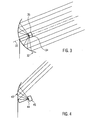
- the prime focus antenna shown in Fig. 3
- the focal point 34 is directly at the front and center of the reflector 32, thus the reflector is symmetric with respect to the symmetry axis of the parabolic surface, as already mentioned above.
- the focal point 34 is positioned a receiving apparatus 35.
- An off-set antenna is shown in Fig. 4 .
- the focal point 44 is no longer positioned at the front and center of the reflector 43 but rather offset.
- the offset antenna offers an important advantage over its prime focus counterparts. There is no horn blockage, so that all the surface can reflect the incoming radiation.
- the cassegrain antenna comprises besides the reflector a small subreflector located at the front and center of the relfector.
- the common parabolic reflector used for satellite video broadcasting is in a diameter ranging from 60-80 cm, depending on the level of the received signal and the receiving apparatus is generally positioned at a distance of about 50 cm from the reflector surface.
- the receiving apparatus placed in the focus of the parabola, is maintained in its position by means of a strut connected to the reflector. Therefore, the antenna presents a rather large size in the horizontal plane because the reflector is oriented toward the satellite direction and the receiving apparatus is connected with a strut to the parabolic reflector.
- Video satellite antennas are typically fixed on balconies or at the walls of the buildings. This presents several disadvantages due to the dimensions and the shape of the parabolic antenna.
- the curved surface of the reflector and the strut which hold the receiver need a relevant space and the geometry of the antenna is not suited to be integrated with the building.
- the result is that typical parabolic antenna have a high environmental impact, modifying the architectural structure of the building and reducing the available space.
- Examples of satellite reception antennas can be found in WO 00/35049 A and US 6208314 B1 .
- An example of a method of making a dish-shaped antenna reflector can be found in US 3 169 311 A .
- An example of a satellite dish cover can be found in GB2 246 242 A .
- patch antennas could be used. They look like flat panel whose thickness is of a few centimeters and no strut is needed to fix the receiver apparatus.
- the environmental impact is not negligible because the panel must be directed to point toward the satellite direction. This means that for example at the latitude of northern Italy the antenna has to point a satellite which has an elevation of about 36°. Therefore, also this kind of antennas are not suited for the integration with the structure of a building.
- the antenna beam In order to have a panel mounted in a vertical position, the antenna beam must be shifted from the broadside direction by means of a complex feeding system which gives the correct phase shifting to the various patches.
- the present invention relates to a tailor-made off-set reflector antenna for satellite video broadcasting, which is highly integrable in the surrounding building structure and has a low environmental impact. This is achieved thanks to the vertical profile of the reflector and to the receiver apparatus, which is disconnected from the reflector. Moreover, the vertical panel containing the reflector which has a low curvature, can be fixed parallel to the building's wall. This solution allows a reduction of the occupied space and in particular, the panel can be mounted flush with the wall. Furthermore a vertical sundial or any other subject can be printed on the panel containing the reflector, so to make the reflector not visible and thus further reducing the environmental impact.
- a receiving antenna for satellite video broadcasting comprises a reflector and a receiving apparatus, wherein the rim of the reflector lies in a vertical plane and the reflector is unconstrained from the receiving apparatus.
- the antenna consists of an offset parabolic reflector. Moreover, the reflector rim lies in a vertical plane whose azimuth can be different from that of the satellite direction.
- the reflector of the present invention has a low curvature; in this way the occupied space is reduced and the integrability of the antenna is improved.
- a vertical sundial is printed on the reflector of the present invention; in this way the integrability of the antenna is improved and the reflector can work at the same time as reflector for the electromagnetic radiation and as vertical sundial.
- the geometrical structure data of the reflector of the present invention are determined by the specific data related to the particular installation site of the receiving antenna (tailor-made geometry); in this way the structure of the reflector present a high flexibility and can be adapted to each particular site.
- the azimuth position of the antenna of the present invention can be adjusted by setting the time read on the sundial; in this way the antenna can be easily installed.
- the present invention relates to method for installing a receiving antenna comprising: setting the vertical position of the panel containing the reflector and setting its azimuth according to that of the wall where the panel will be mounted.
- the present invention relates to method for installing a receiving antenna comprising: setting the vertical position of the panel containing the reflector and setting its azimuth, wherein the azimuth position is adjusted by setting the time read on the sundial; in this way the installation procedure is facilitate. according to that of the wall where the panel will be mounted.
- the present invention relates to method for fabricating a receiving antenna, wherein the geometrical structure data of the reflector depends from the specific data related to the particular installation site of the receiving antenna; in this way the receiving antenna geometry is always adapted to the particular installation site, improving its integrability.
- the present invention relates to a low environmental impact receiving antenna for satellite video broadcasting which is easily integrable in the surrounding building structure.
- the receiving antenna according to the present invention comprises an offset parabolic reflector and a receiving apparatus, which are separated from each other.
- the reflector is a section of a parabolic surface. Thanks to the separation between the reflector and the receiving apparatus, it is possible to choose a parabolic surface with a large focal distance, and therefore, the reflector presents a low curvature.
- the reflector is an offset parabolic reflector. Moreover, the separation of the reflector and the receiving apparatus allows the reduction of the horizontal extension of the antenna, therefore reducing the overall occupied space.
- the parabolic reflector has almost a flat shape and it is mounted in a vertical position with the azimuth defined by the architectural constraints. This allows fixing the reflector directly to the walls of the building, thus making the receiving antenna, according to the present invention, highly integrable in the surrounding environment.
- the present invention relates to a vertical sundial acting as a receiving antenna.
- a further advantage according to an embodiment of the present invention can be obtained by using the almost flat vertical reflector of the receiving antenna as a sundial.
- the surface of the reflector can advantageously be used at the same time for two different scopes, namely as a reflector of the electromagnetic radiation and also as a sundial.
- This multi-usage solution allows different advantages, in fact, in this way, the antenna reflector which generally is situated on the balcony of a building is not recognizable anymore, thus improving the integration in the building structure and reducing the environmental impact of the same.
- the solution according to the present invention allows for significant reduction of the occupied space, in fact, instead of having two separate elements fixed on a balcony or on the wall of a building, the present invention provides a parabolic surface section, which at the same time acts as a reflector antenna and a sundial.
- the sundial printed on the reflector can be used to verify and, in case, to adjust the azimuth of the panel containing the reflector, in fact the azimuth position of the antenna can be obtained by setting the time read on the vertical sundial.
- Figure 5 schematically illustrates a cross sectional view of the receiving antenna for satellite video broadcasting in its plane of symmetry according to the present invention.
- the reflector 1 reflects the electromagnetic radiation 5 sent by the satellite so that the radiation is directed to the receiving apparatus 4.
- the reflector 1 is a section of the parabolic surface 2.
- the rim of the reflector 1 has an elliptic form and lies in a vertical plane parallel to the plane 6.
- the receiving apparatus 4 is positioned on the focal point 3 of the parabolic surface 2.
- the reflector 1 and the receiving apparatus 4 are not connected to each other; this allows a high degree of freedom in the positioning of the reflector with respect to the receiving apparatus.
- the reflector 1 is a section of a parabolic surface with a large focal distance.
- the focal distance of the parabolic surface 2 according to the present invention is determined by architectural considerations and not by electromagnetic considerations.
- a large focal distance has the advantage of significantly reducing the curvature of the parabolic reflector.
- the reflector 1 is not symmetric with respect to the symmetry axis 8 of the parabolic surface 2 and it is, therefore, an offset parabolic reflector. Thanks to the low curvature, the reflector 1 has almost a flat shape.
- the reflector 1 is defined so that its rim lies in a vertical plane whose azimuth is set by architectural constraints (wall of the building 6). In this way the panel containing the reflector 1 can be fixed to the walls 6 of the building.
- the receiving apparatus is directed towards the reflector 1 and, in a particular embodiment according to the present invention, in order to increase the directivity, a metallic frustum of cone can be mounted on that.
- the receiving apparatus 4 can be fixed to a balcony or it can be put into a flower box or in other hidden places so as to have a minimal environmental impact.
- the camouflage of the receiving apparatus 4 is not critical due to its reduced dimensions and because it is oriented toward the reflector 1 mounted on the wall 6.
- the separation between the receiver and the reflector makes the system more flexible, giving a higher degree of freedom in the choice of the position of the receiver and the reflector (this is an input data in the design of the antenna geometry).
- the position of the receiver with respect to the reflector depends on the particular site.
- the parabolic surface of the reflector has to be designed according to the specific data related to the particular site.
- the antenna In order to determine the geometry of the entire antenna, the following data are necessary: the elevation of the satellite line-of-sight, the azimuth of the satellite line-of-sight, the azimuth of the wall where the vertical sundial will be mounted, the position where the receiving apparatus will be placed, the diameter of the reflector projection along the satellite direction (it depends on the received signal level). Therefore the antenna has a tailor-made geometry which depends on the particular position of the installation.
- the offset reflector 1 is defined by the intersection of the axially symmetric parabolic surface 2 and the cone 7 with its vertex at the focal point 3.
- the geometry is determined by: the focal length f of the parabolic surface, the angle ⁇ 0 between the cone axis 5 and focal axis 8, and the angular aperture ⁇ c of the cone 7 which defines the reflector rim.
- the design input data are different because they are related to architectural constraints. They can be expressed by these following three parameters:
- the plane of symmetry sketched in figure 5 is defined by the satellite direction and the direction perpendicular to the vertical plane. In general, it is not a vertical plane; in particular it becomes vertical if the two directions mentioned above have the same azimuth.
- D m 4 ⁇ f ⁇ sin ⁇ c cos ⁇ c + cos ⁇ c
- D M 4 ⁇ f ⁇ sin ⁇ c ⁇ cos ⁇ c + cos ⁇ c 2 + sin 2 ⁇ ⁇ 0 cos ⁇ 0 + cos ⁇ c 2
- ⁇ c is the angular aperture of the cone 7 which defines the reflector rim
- ⁇ 0 is the angle between the cone axis 5 and focal axis 8
- f is the focal length of the parabolic surface
- D m and D M are the principal diameters of the ellipse which defines the vertical reflector rim.
- the vertical reflector rim is elliptical with principle diameters of 887 mm and 700 mm, respectively, and an axial ratio of 1.26.
- the focal length is 1177 mm.
- the rim is suspended by a cone with a semi aperture of 10°.6 whose axis is inclined to 75° with respect to the focal axis.
- this parabolic surface of the reflector was obtained by excavating the 40 mm thick panel with a size of 800 mm x 1000 mm made of extruded rigid polystyrene. Then the reflecting properties were obtained by sticking an aluminum adhesive tape on the parabolic surface. The panel was then covered by a PVC sheet on which the vertical sundial was printed.
- Figure 6,7 show a three-dimensional view and a front view of the parabolic reflector, according to a particular embodiment of the present invention.
- the rim of the reflector is elliptic and the reflecting surface lies on a vertical plane.
- the front view of the reflector is presented with its iso-level curves whose values are expressed in millimeters, it is possible to see that the maximum depth of the parabolic reflector is just 20 mm.
- the fabrication of the receiving antenna according to the present invention are more complicated than in the case of a standard parabolic antenna for video receiving, where the shape and dimensions of the antenna do not depend from the installation position and the receiver is held in the focal point by a strut. Nevertheless, this additional work is largely compensated by the advantages connected the improvement of the integrability of the antenna.
- the reflector can be pointed toward the satellite direction without making reference to the received signal level.
- the panel has to be mounted in the vertical position (a plunb line is sufficient) and flush with wall whose azimuth was previously taken.
- the presence of the vertical sundial on the surface of the reflector allows one to verify and, in case, to correct the azimuth of the reflector.
- the position of the reflector is directly related the time read on the sundial.
- the sundial hour-lines have to be designed according to the mean time of the relevant time zone, in this example the Central European Time (CET), and not to solar time.
- CET Central European Time
- the lines are not straight but have an 8-shaped geometry known as analemma, so that the mean time can be directly read on the sundial.
- the receiving apparatus is made of a low noise block (LNB) with an aperture diameter of about 50 mm.
- LNB low noise block
- a frustum of cone made of a copper layer with the diameter of 130 mm and an angle of 70° was mounted in front of the LNB. In this way, the total length of the horn plus the LNB was about 230 mm.
- the aperture of the new horn was covered with a polystyrene window and the lateral surface was covered with an epoxy resin to give solidity to the whole structure. The correct position of the LNB is obtained starting from the position of the previously mounted panel containing the reflector.
- a "trompe l'oeil" or other subjects could be printed on it in order to make receiving antenna not visible, therefore reducing the environmental impact of the system on the surrounding building structure.
- the antenna is designed according to the particular position of the installation.
- the antenna consists of an offset parabolic reflector whose elliptic rim lies on a vertical plane on which a vertical sundial is placed.
- the horn is not mechanically connected to the reflector and is placed in a convenient position such as inside a flower box or other hidden places, so that the existing environment is preserved.
- the camouflage of the horn is not critical due to its reduced dimensions and because it oriented toward the reflector mounted on the wall.
- the elliptical profile of the reflector lies on the vertical plane whose azimuth is defined by architectural considerations and it can be different from that of the satellite direction; moreover the dish is unconstrained from the receiving apparatus whose position is defined by architectural considerations as well. Hence, it can be easily integrated in the wall. In particular, thanks to its small thickness it can be mounted even flush with the wall.
Landscapes
- Engineering & Computer Science (AREA)
- Manufacturing & Machinery (AREA)
- Physics & Mathematics (AREA)
- Electromagnetism (AREA)
- Aerials With Secondary Devices (AREA)
- Waveguide Aerials (AREA)
Abstract
Description
- The present invention relates to the field of receiving antennas for satellite video broadcasting. In particular, the present invention relates to a low environmental impact antenna that is highly integrable. In more detail, the present invention relates to a tailor-made offset reflector with vertical profile and azimuth corresponding to that of the wall where it will be mounted, which, in general, is different from that of the satellite direction.
- Telecommunication is the transmission of signals over a distance for the purpose of communication. Today the process almost always involves the sending of electromagnetic waves by electronic transmitters. Telecommunication is typically used for the transmission of video, audio and data signals. The basic elements of a telecommunication system are: a transmitter that takes information and converts it to a signal to be transmitted, a transmission medium over which the signal is transmitted and a receiver that receives and converts the signal back into usable information.
- Many different methods can be used. Satellite communications employ artificial satellites which orbit around the earth. Communication satellites provide a technology complementary to that of fiber optics, cables and terrestrial wireless communication. The most important application for communication satellites is probably still in the international telephony. Communication satellites are also widely used for television and radio.
- Satellites used for television signals are in geostationary orbit at 37000 km above the earth's equator. Satellite television, like other communications relayed by satellite, starts with a transmitting antenna located at an uplink facility which transmits the signal to the satellite. Then the transponder in the satellite retransmits the signals back to earth but using a different frequency band.
- The downlinked satellite signal, quite weak after travelling the great distance, is collected by a parabolic receiving dish (further on referred to also as parabolic reflector or simply reflector), which reflects the weak signal to the dish's focal point. This is possible thanks to the property of the parabolic surface to concetrate in the focal point the incoming radiation which is parallel to the symmetry axis of the parabola as shown in
Fig. 1 . Mounted on brackets at the dish's focal point there is a device called a horn. This horn is essentially the front-end of a waveguide that gathers the signals at or near the focal point and conducts them to a low-noise block downconverter or LNB. The LNB converts the signals from electromagnetic or radio waves to electrical signals. - The
Fig. 1 shows aparabolic section 12 which is part of aparabolic surface 11. Theparabolic section 12 is symmetric with respect to the symmetry axis 13 of theparabolic surface 11. Anyway this is not the only possibility, in fact as shown inFig. 2 theparabolic section 22 can be also chosen differently. Thesection 22 is not symmetric with respect to thesymmetry axis 23. Theparabolic section 22 works, from a geometrical point of view, as theparabolic section 12 reflecting the incoming radiation which is parallel to thesymmetry axis 23 to thefocal point 24. - The parabolic antenna is a high-gain reflector antenna and it can be used for different scopes as radio, television and data communications, and also for radiolocation (RADAR), on the ultra high (UHF) and super high frequencies (SHF). The relatively short wavelength of electromagnetic waves at these frequencies allows reasonably sized reflectors to exhibit the very desirable highly directional response.
- The parabolic antennas come in varying sizes and designs. The main types of parabolic antennas are: the prime focus antenna, the off-set antenna and the Cassegrain antenna. In the prime focus antenna, shown in
Fig. 3 , thefocal point 34 is directly at the front and center of thereflector 32, thus the reflector is symmetric with respect to the symmetry axis of the parabolic surface, as already mentioned above. In thefocal point 34 is positioned a receiving apparatus 35. An off-set antenna is shown inFig. 4 . Here thefocal point 44 is no longer positioned at the front and center of thereflector 43 but rather offset. The offset antenna offers an important advantage over its prime focus counterparts. There is no horn blockage, so that all the surface can reflect the incoming radiation. Finally the cassegrain antenna comprises besides the reflector a small subreflector located at the front and center of the relfector. - The common parabolic reflector used for satellite video broadcasting is in a diameter ranging from 60-80 cm, depending on the level of the received signal and the receiving apparatus is generally positioned at a distance of about 50 cm from the reflector surface. The receiving apparatus, placed in the focus of the parabola, is maintained in its position by means of a strut connected to the reflector. Therefore, the antenna presents a rather large size in the horizontal plane because the reflector is oriented toward the satellite direction and the receiving apparatus is connected with a strut to the parabolic reflector.
- Video satellite antennas are typically fixed on balconies or at the walls of the buildings. This presents several disadvantages due to the dimensions and the shape of the parabolic antenna. The curved surface of the reflector and the strut which hold the receiver need a relevant space and the geometry of the antenna is not suited to be integrated with the building. The result is that typical parabolic antenna have a high environmental impact, modifying the architectural structure of the building and reducing the available space.
- Examples of satellite reception antennas can be found in
WO 00/35049 A US 6208314 B1 . An example of a method of making a dish-shaped antenna reflector can be found inUS 3 169 311 A . An example of a satellite dish cover can be found inGB2 246 242 A - In order to reduce the dimensions of the antenna, patch antennas could be used. They look like flat panel whose thickness is of a few centimeters and no strut is needed to fix the receiver apparatus. However, the environmental impact is not negligible because the panel must be directed to point toward the satellite direction. This means that for example at the latitude of northern Italy the antenna has to point a satellite which has an elevation of about 36°. Therefore, also this kind of antennas are not suited for the integration with the structure of a building. In order to have a panel mounted in a vertical position, the antenna beam must be shifted from the broadside direction by means of a complex feeding system which gives the correct phase shifting to the various patches. As a matter of fact, this cannot be obtained in a frequency range 10.7 -12.7 GHz and for both vertical and horizontal polarizations. The complex feeding system can be avoid by using a reflect array which consists of a quasi-periodical arrangement of metal patches on a vertical panel illuminated by a horn placed in the focal point. Unfortunately, this configuration presents, for both vertical and horizontal polarizations, a very narrow bandwidth compared with that required for satellite broadcasting. Hence, because of the required bandwidth for both vertical and horizontal polarizations, it is clear that the parabolic reflector is still a low cost solution for receiving the satellite broadcast signal.
- The present invention relates to a tailor-made off-set reflector antenna for satellite video broadcasting, which is highly integrable in the surrounding building structure and has a low environmental impact. This is achieved thanks to the vertical profile of the reflector and to the receiver apparatus, which is disconnected from the reflector. Moreover, the vertical panel containing the reflector which has a low curvature, can be fixed parallel to the building's wall. This solution allows a reduction of the occupied space and in particular, the panel can be mounted flush with the wall. Furthermore a vertical sundial or any other subject can be printed on the panel containing the reflector, so to make the reflector not visible and thus further reducing the environmental impact.
- According to one illustrative embodiment of the present invention a receiving antenna for satellite video broadcasting comprises a reflector and a receiving apparatus, wherein the rim of the reflector lies in a vertical plane and the reflector is unconstrained from the receiving apparatus.
- According to a preferred embodiment, the antenna consists of an offset parabolic reflector. Moreover, the reflector rim lies in a vertical plane whose azimuth can be different from that of the satellite direction.
- According to a further preferred embodiment, the reflector of the present invention has a low curvature; in this way the occupied space is reduced and the integrability of the antenna is improved.
- According to a further preferred embodiment, a vertical sundial is printed on the reflector of the present invention; in this way the integrability of the antenna is improved and the reflector can work at the same time as reflector for the electromagnetic radiation and as vertical sundial.
- According to a further preferred embodiment, the geometrical structure data of the reflector of the present invention are determined by the specific data related to the particular installation site of the receiving antenna (tailor-made geometry); in this way the structure of the reflector present a high flexibility and can be adapted to each particular site.
- According to a further preferred embodiment, the azimuth position of the antenna of the present invention can be adjusted by setting the time read on the sundial; in this way the antenna can be easily installed.
- According to one illustrative embodiment, the present invention relates to method for installing a receiving antenna comprising: setting the vertical position of the panel containing the reflector and setting its azimuth according to that of the wall where the panel will be mounted.
- According to one illustrative embodiment, the present invention relates to method for installing a receiving antenna comprising: setting the vertical position of the panel containing the reflector and setting its azimuth, wherein the azimuth position is adjusted by setting the time read on the sundial; in this way the installation procedure is facilitate. according to that of the wall where the panel will be mounted.
- According to one illustrative embodiment, the present invention relates to method for fabricating a receiving antenna, wherein the geometrical structure data of the reflector depends from the specific data related to the particular installation site of the receiving antenna; in this way the receiving antenna geometry is always adapted to the particular installation site, improving its integrability.
- In the following, a description will be given with reference to the drawings of particular and/or preferred embodiments of the present invention. However, it has to be noted that the present invention is not limited to the embodiments disclosed but that the embodiments disclosed only relate to particular examples of the present invention, the scope of which is defined by the appended claims. In particular, in the drawings:
-
Fig. 1 schematically shows how a section of a parabolic surface symmetric with respect to the symmetry axis of the parabola itself can be used to concentrate the incoming radiation on the focus point; -
Fig. 2 schematically shows how a section of a parabolic surface not symmetric with respect symmetry axis of the parabola can still be used to concentrate the incoming radiation on the focus point; -
Fig. 3 schematically shows a prime focus receiving antenna according to the state of art; -
Fig. 4 schematically shows an offset receiving antenna according to the state of art; -
Fig. 5 schematically shows the symmetry plane section of a receiving antenna according to the present invention; -
Fig. 6 schematically shows a three dimensional view of the reflector and the position of it focal point. -
Fig. 7 schematically shows a front view of the reflector surface of the receiving antenna, wherein the iso-level curves are also reported. The elliptic rim corresponds to level 0 mm and the other levels refer to ellipses slightly shifted down. - While the present invention is described with reference to the embodiments as illustrated in the following detailed description as well as in the drawings, it should be understood that the following detailed description as well as the drawings are not intended to limit the present invention to the particular illustrative embodiments disclosed, but rather the described illustrative embodiments merely exemplify the various aspects of the present invention, the scope of which is defined by the appended claims.
- Generally, the present invention relates to a low environmental impact receiving antenna for satellite video broadcasting which is easily integrable in the surrounding building structure. The receiving antenna according to the present invention comprises an offset parabolic reflector and a receiving apparatus, which are separated from each other. The reflector is a section of a parabolic surface. Thanks to the separation between the reflector and the receiving apparatus, it is possible to choose a parabolic surface with a large focal distance, and therefore, the reflector presents a low curvature. The reflector is an offset parabolic reflector. Moreover, the separation of the reflector and the receiving apparatus allows the reduction of the horizontal extension of the antenna, therefore reducing the overall occupied space. Furthermore, thanks to the low curvature, the parabolic reflector has almost a flat shape and it is mounted in a vertical position with the azimuth defined by the architectural constraints. This allows fixing the reflector directly to the walls of the building, thus making the receiving antenna, according to the present invention, highly integrable in the surrounding environment.
- Moreover, the present invention relates to a vertical sundial acting as a receiving antenna.
- A further advantage according to an embodiment of the present invention can be obtained by using the almost flat vertical reflector of the receiving antenna as a sundial. The surface of the reflector can advantageously be used at the same time for two different scopes, namely as a reflector of the electromagnetic radiation and also as a sundial. This multi-usage solution allows different advantages, in fact, in this way, the antenna reflector which generally is situated on the balcony of a building is not recognizable anymore, thus improving the integration in the building structure and reducing the environmental impact of the same. Furthermore, the solution according to the present invention allows for significant reduction of the occupied space, in fact, instead of having two separate elements fixed on a balcony or on the wall of a building, the present invention provides a parabolic surface section, which at the same time acts as a reflector antenna and a sundial. Moreover, the sundial printed on the reflector can be used to verify and, in case, to adjust the azimuth of the panel containing the reflector, in fact the azimuth position of the antenna can be obtained by setting the time read on the vertical sundial.
- With reference to
figure 5 , illustrative embodiments of the present invention will now be described in more detail. -
Figure 5 schematically illustrates a cross sectional view of the receiving antenna for satellite video broadcasting in its plane of symmetry according to the present invention. The reflector 1 reflects theelectromagnetic radiation 5 sent by the satellite so that the radiation is directed to the receiving apparatus 4. The reflector 1 is a section of the parabolic surface 2. The rim of the reflector 1 has an elliptic form and lies in a vertical plane parallel to the plane 6. The receiving apparatus 4 is positioned on the focal point 3 of the parabolic surface 2. The reflector 1 and the receiving apparatus 4 are not connected to each other; this allows a high degree of freedom in the positioning of the reflector with respect to the receiving apparatus. - In particular, it is possible to choose the reflector 1 as being a section of a parabolic surface with a large focal distance. The focal distance of the parabolic surface 2 according to the present invention is determined by architectural considerations and not by electromagnetic considerations.
- According to the present invention where no constraints are present in the reflector 1 and the receiving apparatus 4, a large focal distance has the advantage of significantly reducing the curvature of the parabolic reflector. As it is shown in
figure 5 , the reflector 1 is not symmetric with respect to the symmetry axis 8 of the parabolic surface 2 and it is, therefore, an offset parabolic reflector. Thanks to the low curvature, the reflector 1 has almost a flat shape. - The reflector 1 is defined so that its rim lies in a vertical plane whose azimuth is set by architectural constraints (wall of the building 6). In this way the panel containing the reflector 1 can be fixed to the walls 6 of the building. The receiving apparatus is directed towards the reflector 1 and, in a particular embodiment according to the present invention, in order to increase the directivity, a metallic frustum of cone can be mounted on that. The receiving apparatus 4 can be fixed to a balcony or it can be put into a flower box or in other hidden places so as to have a minimal environmental impact. The camouflage of the receiving apparatus 4 is not critical due to its reduced dimensions and because it is oriented toward the reflector 1 mounted on the wall 6.
- The separation between the receiver and the reflector makes the system more flexible, giving a higher degree of freedom in the choice of the position of the receiver and the reflector (this is an input data in the design of the antenna geometry). Contrary to a standard receiving antenna where the receiver is held on the focus position by a strut fixed to the reflector, according to the present invention, the position of the receiver with respect to the reflector depends on the particular site. Furthermore, the parabolic surface of the reflector has to be designed according to the specific data related to the particular site.
- In order to determine the geometry of the entire antenna, the following data are necessary: the elevation of the satellite line-of-sight, the azimuth of the satellite line-of-sight, the azimuth of the wall where the vertical sundial will be mounted, the position where the receiving apparatus will be placed, the diameter of the reflector projection along the satellite direction (it depends on the received signal level). Therefore the antenna has a tailor-made geometry which depends on the particular position of the installation.
- With reference to
figure 5 , the offset reflector 1 is defined by the intersection of the axially symmetric parabolic surface 2 and thecone 7 with its vertex at the focal point 3. Hence, the geometry is determined by: the focal length f of the parabolic surface, the angle θ0 between thecone axis 5 and focal axis 8, and the angular aperture θ c of thecone 7 which defines the reflector rim.
However, the design input data are different because they are related to architectural constraints. They can be expressed by these following three parameters: - h: distance between the vertical plane 6 and the point where the horn will be place (focal point 3);
- α : angle between the satellite direction 8 and the direction perpendicular to the vertical plane 8 where the reflector will be mounted
- Dp : diameter of the circular projection of the reflector rim on to the focal plane (perpendicular to the satellite direction);
- It has to be noted that the plane of symmetry sketched in
figure 5 is defined by the satellite direction and the direction perpendicular to the vertical plane. In general, it is not a vertical plane; in particular it becomes vertical if the two directions mentioned above have the same azimuth. - Starting from these design parameters h, Dp and α, it is possible to define the entire antenna geometry through the following equations:


where θ c is the angular aperture of thecone 7 which defines the reflector rim, θ0 is the angle between thecone axis 5 and focal axis 8, f is the focal length of the parabolic surface, Dm and DM are the principal diameters of the ellipse which defines the vertical reflector rim. - As an example, we consider the installation of a receiving antenna on the first floor of a house in the Italian town of Turin. The town of Turin is located at a latitude of 45°.05 N and at the longitude of 7°.63 E. The satellite considered is the Hotbird 13° E which at the chosen position is seen at an elevation of 37°.86 and an azimuth of 172.44°. The azimuth of the vertical sundial was chosen for convenience to be equal to the satellite direction (172.44°). in this way the angle α was set to 52.14° It has to be noted that the azimuth of the vertical sundial could also be chosen differently. The horn was placed inside the flower box hanging on the outer side of the terrace banister. In this way, the focus of the antenna is placed at h = 147 cm from the vertical plane where the sundial has to be mounted. The diameter of the antenna projected aperture toward the satellite direction was set to DP =70 cm.
- With these data the antenna geometry was defined according to the equations given above. The solution for this particular case is described by the following data: the vertical reflector rim is elliptical with principle diameters of 887 mm and 700 mm, respectively, and an axial ratio of 1.26. The focal length is 1177 mm. The rim is suspended by a cone with a semi aperture of 10°.6 whose axis is inclined to 75° with respect to the focal axis.
- In this particular case, this parabolic surface of the reflector was obtained by excavating the 40 mm thick panel with a size of 800 mm x 1000 mm made of extruded rigid polystyrene. Then the reflecting properties were obtained by sticking an aluminum adhesive tape on the parabolic surface. The panel was then covered by a PVC sheet on which the vertical sundial was printed.
-
Figure 6,7 show a three-dimensional view and a front view of the parabolic reflector, according to a particular embodiment of the present invention. As it is possible to see from the figure, the rim of the reflector is elliptic and the reflecting surface lies on a vertical plane. Infigure 7 , wherein the front view of the reflector is presented with its iso-level curves whose values are expressed in millimeters, it is possible to see that the maximum depth of the parabolic reflector is just 20 mm. - The fabrication of the receiving antenna according to the present invention are more complicated than in the case of a standard parabolic antenna for video receiving, where the shape and dimensions of the antenna do not depend from the installation position and the receiver is held in the focal point by a strut. Nevertheless, this additional work is largely compensated by the advantages connected the improvement of the integrability of the antenna.
- Thank to the TAILOR-made geometry the reflector can be pointed toward the satellite direction without making reference to the received signal level. In fact, the panel has to be mounted in the vertical position (a plunb line is sufficient) and flush with wall whose azimuth was previously taken. It has to be noted that the presence of the vertical sundial on the surface of the reflector allows one to verify and, in case, to correct the azimuth of the reflector. In fact, the position of the reflector is directly related the time read on the sundial. For this purpose, the sundial hour-lines have to be designed according to the mean time of the relevant time zone, in this example the Central European Time (CET), and not to solar time. In other words, they take into account the "equation of time" and the shift of the mean solar time due to the longitude of the site. Hence, the lines are not straight but have an 8-shaped geometry known as analemma, so that the mean time can be directly read on the sundial.
- In a particular embodiment according to the present invention, the receiving apparatus is made of a low noise block (LNB) with an aperture diameter of about 50 mm. However, due to the rather small angle at which the dish is seen from the focal point, a larger aperture diameter is necessary. In order to have a directivity of 20 dB and the illumination tapering on the dish of about -7 dB, a frustum of cone made of a copper layer with the diameter of 130 mm and an angle of 70° was mounted in front of the LNB. In this way, the total length of the horn plus the LNB was about 230 mm. The aperture of the new horn was covered with a polystyrene window and the lateral surface was covered with an epoxy resin to give solidity to the whole structure. The correct position of the LNB is obtained starting from the position of the previously mounted panel containing the reflector.
- In a further embodiment according to the present invention, instead of a vertical sundial on the reflector surface, a "trompe l'oeil" or other subjects could be printed on it in order to make receiving antenna not visible, therefore reducing the environmental impact of the system on the surrounding building structure.
- The idea presented in this document regards a low cost solution where the antenna is designed according to the particular position of the installation. From electromagnetic point of view the antenna, according to an embodiment of the present invention, it consists of an offset parabolic reflector whose elliptic rim lies on a vertical plane on which a vertical sundial is placed. The horn is not mechanically connected to the reflector and is placed in a convenient position such as inside a flower box or other hidden places, so that the existing environment is preserved. The camouflage of the horn is not critical due to its reduced dimensions and because it oriented toward the reflector mounted on the wall.
- The peculiarities of the idea are that the elliptical profile of the reflector lies on the vertical plane whose azimuth is defined by architectural considerations and it can be different from that of the satellite direction; moreover the dish is unconstrained from the receiving apparatus whose position is defined by architectural considerations as well. Hence, it can be easily integrated in the wall. In particular, thanks to its small thickness it can be mounted even flush with the wall.
- Further modifications and variations of the present invention will be apparent to those skilled in the art in view of this description. Accordingly, the description is to be construed as illustrative only and is for the purpose of teaching those skilled in the art the general manner of carrying out the present invention. It is to be understood that the forms of the invention shown and described herein are to be taken as the presently preferred embodiments.
Claims (21)
- Offset receiving antenna for satellite video broadcasting comprising:a parabolic reflector (1); anda receiving apparatus (4) for collecting the electromagnetic waves reflected by said reflector (1)characterized in thata rim of said reflector (1) lies in a vertical plane,said reflector (1) is adapted to be mounted on a wall (6) of a building so that the rim of said reflector (1) lies in the vertical plane parallel to said wall (6) and said reflector (1) is not mechanically connected to the receiving apparatus (4).
- A receiving antenna as in claim 1
characterized in that
the surface of said reflector (1) presents a low curvature so that the maximum depth of said reflector (1) is 20 mm or less. - A receiving antenna as in claim 1
characterized in that
a sundial is printed on said reflector (1). - A receiving antenna as in claim 1
characterized in that
said rim of said parabolic reflector (1) is elliptic. - A receiving antenna as in claim 1
characterized in that
the receiving apparatus (4) is placed in the focus of said parabolic reflector (1). - A receiving antenna as in claim 1
characterized in that
the surface of the reflector (1) is obtained by excavating a panel made of extruded rigid polystyrene. - A receiving antenna as in claim 6
characterized in that
the surface of the reflector (1) is covered by a reflecting material. - A receiving antenna as in claim 7
characterized in that
said reflecting material is an aluminium adhesive tape. - A receiving antenna as in claim 7
characterized in that
said reflecting material is covered by a PVC sheet. - A receiving antenna as in claim 9 and 3
characterized in that
said sundial is printed on said PVC sheet. - A receiving antenna as in claim 1
characterized in that
the geometrical structure data of the reflector (1) are determined by the specific data related to the particular installation site of the receiving antenna. - A receiving antenna as in claim 11
characterized in that
the geometrical structure data include the dimensions of the reflector (1). - A receiving antenna as in claim 11
characterized in that
the geometrical structure data include the focal length of said parabolic reflector (1). - A receiving antenna as in claim 1
characterized in that
a "trompe l'oeil" or other image which can create an optical illusion is printed on said reflector (1). - A receiving antenna as in claim 4
characterized in that
the azimuth of the panel containing the reflector is defined according to architectural considerations and it can be different from the azimuth of the satellite direction. - A receiving antenna as in claim 3
characterized in that
the azimuth position of said antenna can be adjusted by setting the time read on the sundial. - A method for fabricating an offset receiving antenna for satellite video broadcasting as claimed in one of claims 1 to 16
characterized in that
said method comprises the following steps:a) determining the architectural constraints of the installation site of the receiving antenna; andb) determining the geometry of the reflector (1) of said antenna on the basis of said architectural constraints. - A method as claimed in claim 17
characterized in that
said step of determining the architectural constraints of the installation site of the receiving antenna comprises the following substeps:a1) determining the point where the receiving apparatus (4) of said antenna will be placed; anda2) determining the azimuthal orientation of the wall (6) where the reflector (1) will be mounted. - A method as claimed in one of claims 17 and 18
characterized in that
said step of determining the architectural constraints of the installation site of the receiving antenna comprises the following substeps:a1) determining the distance (h) between the vertical plane and the point where the receiving apparatus will be placed;a2) determining the angle (α) between the emitting satellite direction (8) and the direction perpendicular to the wall (6) where the reflector (1) will be mounted; anda3) determining the diameter (DP ) of the reflector projection along the satellite direction (8). - A method as claimed in one of claims 17 to 19
characterized in that
said step of determining the geometry of the reflector (1) of said antenna comprises determining the following parameters: angular aperture (θ c ) of the cone (7) which defines the reflector rim, angle (θ o ) between the axis (5) of said cone (7) and the focal axis (8), focal length (f) of the parabolic surface, principal diameters (DM, Dm ) which define the rim of said reflector (1). - A method as claimed in one of claims 17 to 20
characterized in that
it further comprises the step of printing a sundial on said reflector (1) so that the azimuth position of the antenna can be adjusted by setting the time read on said sundial.
Priority Applications (5)
| Application Number | Priority Date | Filing Date | Title |
|---|---|---|---|
| PL07002756T PL1956677T3 (en) | 2007-02-08 | 2007-02-08 | High integrable flat antenna for satellite video receiving |
| ES07002756T ES2357638T3 (en) | 2007-02-08 | 2007-02-08 | HIGHLY INTEGRABLE FLAT ANTENNA FOR SATELLITE VIDEO RECEPTION. |
| DE602007011193T DE602007011193D1 (en) | 2007-02-08 | 2007-02-08 | Highly integrated flat antenna for receiving satellite TV |
| AT07002756T ATE492046T1 (en) | 2007-02-08 | 2007-02-08 | HIGHLY INTEGRATED FLAT ANTENNA FOR RECEIVING SATELLITE TELEVISION |
| EP07002756A EP1956677B1 (en) | 2007-02-08 | 2007-02-08 | High integrable flat antenna for satellite video receiving |
Applications Claiming Priority (1)
| Application Number | Priority Date | Filing Date | Title |
|---|---|---|---|
| EP07002756A EP1956677B1 (en) | 2007-02-08 | 2007-02-08 | High integrable flat antenna for satellite video receiving |
Publications (2)
| Publication Number | Publication Date |
|---|---|
| EP1956677A1 EP1956677A1 (en) | 2008-08-13 |
| EP1956677B1 true EP1956677B1 (en) | 2010-12-15 |
Family
ID=38197772
Family Applications (1)
| Application Number | Title | Priority Date | Filing Date |
|---|---|---|---|
| EP07002756A Not-in-force EP1956677B1 (en) | 2007-02-08 | 2007-02-08 | High integrable flat antenna for satellite video receiving |
Country Status (5)
| Country | Link |
|---|---|
| EP (1) | EP1956677B1 (en) |
| AT (1) | ATE492046T1 (en) |
| DE (1) | DE602007011193D1 (en) |
| ES (1) | ES2357638T3 (en) |
| PL (1) | PL1956677T3 (en) |
Family Cites Families (14)
| Publication number | Priority date | Publication date | Assignee | Title |
|---|---|---|---|---|
| US3169311A (en) | 1961-06-28 | 1965-02-16 | Bernard I Small | Method of making a dish-shaped antenna reflector |
| US4035065A (en) * | 1975-09-24 | 1977-07-12 | Nasa | Lightweight reflector assembly |
| GB2120854A (en) * | 1982-04-16 | 1983-12-07 | Fastwool Limited | Antennas |
| GB2211609A (en) * | 1987-10-27 | 1989-07-05 | Argosy Electronics Limited | Alignment device |
| GB8817885D0 (en) * | 1988-07-27 | 1988-09-01 | British Telecomm | Antenna |
| GB2246242B (en) | 1990-06-02 | 1994-07-20 | Michael Brassington | Cover |
| JPH0936635A (en) * | 1995-07-13 | 1997-02-07 | Toppan Printing Co Ltd | Satellite antenna |
| US6208316B1 (en) | 1995-10-02 | 2001-03-27 | Matra Marconi Space Uk Limited | Frequency selective surface devices for separating multiple frequencies |
| DE29611497U1 (en) * | 1996-07-02 | 1997-03-06 | Woltmann, Thorsten, 25788 Delve | Satellite dish protection device |
| FR2753007B1 (en) * | 1996-09-04 | 1998-11-27 | Bourquin Patrick | SATELLITE RECEPTION ANTENNA |
| DE19819091C1 (en) * | 1998-04-29 | 1999-02-18 | Christian Schwaiger Gmbh & Co | Satellite antenna with sun dial |
| US6686889B1 (en) | 1998-12-08 | 2004-02-03 | Tae I. Kwon | Method and apparatus for antenna orientation and antenna with the same |
| ES2153323B1 (en) * | 1999-06-07 | 2001-07-16 | Univ Madrid Politecnica | FLAT REFLECTORS IN MULTI-PAPER PRINTED TECHNOLOGY AND ITS DESIGN PROCEDURE. |
| KR20040039441A (en) * | 2001-09-28 | 2004-05-10 | 스미토모덴키고교가부시키가이샤 | Radio wave lens antenna apparatus |
-
2007
- 2007-02-08 DE DE602007011193T patent/DE602007011193D1/en active Active
- 2007-02-08 ES ES07002756T patent/ES2357638T3/en active Active
- 2007-02-08 EP EP07002756A patent/EP1956677B1/en not_active Not-in-force
- 2007-02-08 AT AT07002756T patent/ATE492046T1/en active
- 2007-02-08 PL PL07002756T patent/PL1956677T3/en unknown
Also Published As
| Publication number | Publication date |
|---|---|
| ATE492046T1 (en) | 2011-01-15 |
| EP1956677A1 (en) | 2008-08-13 |
| DE602007011193D1 (en) | 2011-01-27 |
| ES2357638T3 (en) | 2011-04-28 |
| PL1956677T3 (en) | 2011-05-31 |
Similar Documents
| Publication | Publication Date | Title |
|---|---|---|
| US10483637B2 (en) | Method and apparatus for beam-steerable antenna with single-drive mechanism | |
| US9281561B2 (en) | Multi-band antenna system for satellite communications | |
| US10615498B2 (en) | Multi-beam shaped reflector antenna for concurrent communication with multiple satellites | |
| KR101045809B1 (en) | Tracking antenna device for 3 band satellite communication | |
| US6535176B2 (en) | Multi-feed reflector antenna | |
| KR101230591B1 (en) | Dual band satellite communication antenna system for sea | |
| JPH02228103A (en) | Conical horn antenna | |
| DE69710081D1 (en) | AERIAL FOR SATELLITE RECEPTION | |
| KR101176920B1 (en) | Skew angle auto controller of satellite antennas for vehicle | |
| US3133284A (en) | Paraboloidal antenna with compensating elements to reduce back radiation into feed | |
| TW471197B (en) | Integrated type bi-direction feed-in electromagnetic apparatus | |
| EP1956677A1 (en) | High integrable flat antenna for satellite video receiving | |
| US20130342412A1 (en) | Antenna feedhorn with one-piece feedcap | |
| KR20030085358A (en) | Satellite communication antenna using multiplex frequency band | |
| US7102585B2 (en) | Integrated feed horn device | |
| KR101640518B1 (en) | Dual-band signal a single antenna systems for satellite communications | |
| KR980009775U (en) | Elevation Indicator for Parabolic Antenna | |
| GB2278020A (en) | Antenna | |
| GB2231445A (en) | Aerial system | |
| JP2871536B2 (en) | Mobile satellite communication system | |
| CN1148835C (en) | Combined bidirectional feed-in device of satellite antenna | |
| US11165162B1 (en) | Dichroic spherical antenna | |
| JP3005229B2 (en) | Mirror modified antenna | |
| JPH1117445A (en) | Antenna device and adjustment method thereof | |
| JP2000040914A (en) | Antenna device |
Legal Events
| Date | Code | Title | Description |
|---|---|---|---|
| PUAI | Public reference made under article 153(3) epc to a published international application that has entered the european phase |
Free format text: ORIGINAL CODE: 0009012 |
|
| AK | Designated contracting states |
Kind code of ref document: A1 Designated state(s): AT BE BG CH CY CZ DE DK EE ES FI FR GB GR HU IE IS IT LI LT LU LV MC NL PL PT RO SE SI SK TR |
|
| AX | Request for extension of the european patent |
Extension state: AL BA HR MK RS |
|
| AKX | Designation fees paid | ||
| 17P | Request for examination filed |
Effective date: 20090604 |
|
| RBV | Designated contracting states (corrected) |
Designated state(s): AT BE BG CH CY LI |
|
| RBV | Designated contracting states (corrected) |
Designated state(s): AT BE BG CH CY CZ DE DK EE ES FI FR GB GR HU IE IS IT LI LT LU LV MC NL PL PT RO SE SI SK TR |
|
| REG | Reference to a national code |
Ref country code: DE Ref legal event code: 8566 |
|
| RBV | Designated contracting states (corrected) |
Designated state(s): AT BE BG CH CY CZ DE DK EE ES FI FR GB GR HU IE IS IT LI LT LU LV MC NL PL PT RO SE SI SK TR |
|
| GRAP | Despatch of communication of intention to grant a patent |
Free format text: ORIGINAL CODE: EPIDOSNIGR1 |
|
| RAP1 | Party data changed (applicant data changed or rights of an application transferred) |
Owner name: SISVEL TECHNOLOGY SRL. |
|
| GRAS | Grant fee paid |
Free format text: ORIGINAL CODE: EPIDOSNIGR3 |
|
| GRAA | (expected) grant |
Free format text: ORIGINAL CODE: 0009210 |
|
| AK | Designated contracting states |
Kind code of ref document: B1 Designated state(s): AT BE BG CH CY CZ DE DK EE ES FI FR GB GR HU IE IS IT LI LT LU LV MC NL PL PT RO SE SI SK TR |
|
| REG | Reference to a national code |
Ref country code: GB Ref legal event code: FG4D Ref country code: CH Ref legal event code: EP |
|
| REG | Reference to a national code |
Ref country code: IE Ref legal event code: FG4D |
|
| REF | Corresponds to: |
Ref document number: 602007011193 Country of ref document: DE Date of ref document: 20110127 Kind code of ref document: P |
|
| REG | Reference to a national code |
Ref country code: CH Ref legal event code: NV Representative=s name: MICHELI & CIE SA |
|
| REG | Reference to a national code |
Ref country code: NL Ref legal event code: T3 |
|
| REG | Reference to a national code |
Ref country code: ES Ref legal event code: FG2A Ref document number: 2357638 Country of ref document: ES Kind code of ref document: T3 Effective date: 20110428 |
|
| PG25 | Lapsed in a contracting state [announced via postgrant information from national office to epo] |
Ref country code: LT Free format text: LAPSE BECAUSE OF FAILURE TO SUBMIT A TRANSLATION OF THE DESCRIPTION OR TO PAY THE FEE WITHIN THE PRESCRIBED TIME-LIMIT Effective date: 20101215 |
|
| LTIE | Lt: invalidation of european patent or patent extension |
Effective date: 20101215 |
|
| PG25 | Lapsed in a contracting state [announced via postgrant information from national office to epo] |
Ref country code: SI Free format text: LAPSE BECAUSE OF FAILURE TO SUBMIT A TRANSLATION OF THE DESCRIPTION OR TO PAY THE FEE WITHIN THE PRESCRIBED TIME-LIMIT Effective date: 20101215 Ref country code: LV Free format text: LAPSE BECAUSE OF FAILURE TO SUBMIT A TRANSLATION OF THE DESCRIPTION OR TO PAY THE FEE WITHIN THE PRESCRIBED TIME-LIMIT Effective date: 20101215 Ref country code: FI Free format text: LAPSE BECAUSE OF FAILURE TO SUBMIT A TRANSLATION OF THE DESCRIPTION OR TO PAY THE FEE WITHIN THE PRESCRIBED TIME-LIMIT Effective date: 20101215 Ref country code: CY Free format text: LAPSE BECAUSE OF FAILURE TO SUBMIT A TRANSLATION OF THE DESCRIPTION OR TO PAY THE FEE WITHIN THE PRESCRIBED TIME-LIMIT Effective date: 20101215 Ref country code: SE Free format text: LAPSE BECAUSE OF FAILURE TO SUBMIT A TRANSLATION OF THE DESCRIPTION OR TO PAY THE FEE WITHIN THE PRESCRIBED TIME-LIMIT Effective date: 20101215 Ref country code: BG Free format text: LAPSE BECAUSE OF FAILURE TO SUBMIT A TRANSLATION OF THE DESCRIPTION OR TO PAY THE FEE WITHIN THE PRESCRIBED TIME-LIMIT Effective date: 20110315 |
|
| REG | Reference to a national code |
Ref country code: PL Ref legal event code: T3 |
|
| PG25 | Lapsed in a contracting state [announced via postgrant information from national office to epo] |
Ref country code: IS Free format text: LAPSE BECAUSE OF FAILURE TO SUBMIT A TRANSLATION OF THE DESCRIPTION OR TO PAY THE FEE WITHIN THE PRESCRIBED TIME-LIMIT Effective date: 20110415 Ref country code: BE Free format text: LAPSE BECAUSE OF FAILURE TO SUBMIT A TRANSLATION OF THE DESCRIPTION OR TO PAY THE FEE WITHIN THE PRESCRIBED TIME-LIMIT Effective date: 20101215 Ref country code: PT Free format text: LAPSE BECAUSE OF FAILURE TO SUBMIT A TRANSLATION OF THE DESCRIPTION OR TO PAY THE FEE WITHIN THE PRESCRIBED TIME-LIMIT Effective date: 20110415 Ref country code: GR Free format text: LAPSE BECAUSE OF FAILURE TO SUBMIT A TRANSLATION OF THE DESCRIPTION OR TO PAY THE FEE WITHIN THE PRESCRIBED TIME-LIMIT Effective date: 20110316 Ref country code: CZ Free format text: LAPSE BECAUSE OF FAILURE TO SUBMIT A TRANSLATION OF THE DESCRIPTION OR TO PAY THE FEE WITHIN THE PRESCRIBED TIME-LIMIT Effective date: 20101215 Ref country code: EE Free format text: LAPSE BECAUSE OF FAILURE TO SUBMIT A TRANSLATION OF THE DESCRIPTION OR TO PAY THE FEE WITHIN THE PRESCRIBED TIME-LIMIT Effective date: 20101215 |
|
| PG25 | Lapsed in a contracting state [announced via postgrant information from national office to epo] |
Ref country code: SK Free format text: LAPSE BECAUSE OF FAILURE TO SUBMIT A TRANSLATION OF THE DESCRIPTION OR TO PAY THE FEE WITHIN THE PRESCRIBED TIME-LIMIT Effective date: 20101215 Ref country code: RO Free format text: LAPSE BECAUSE OF FAILURE TO SUBMIT A TRANSLATION OF THE DESCRIPTION OR TO PAY THE FEE WITHIN THE PRESCRIBED TIME-LIMIT Effective date: 20101215 |
|
| PG25 | Lapsed in a contracting state [announced via postgrant information from national office to epo] |
Ref country code: MC Free format text: LAPSE BECAUSE OF NON-PAYMENT OF DUE FEES Effective date: 20110228 |
|
| PLBE | No opposition filed within time limit |
Free format text: ORIGINAL CODE: 0009261 |
|
| STAA | Information on the status of an ep patent application or granted ep patent |
Free format text: STATUS: NO OPPOSITION FILED WITHIN TIME LIMIT |
|
| PG25 | Lapsed in a contracting state [announced via postgrant information from national office to epo] |
Ref country code: DK Free format text: LAPSE BECAUSE OF FAILURE TO SUBMIT A TRANSLATION OF THE DESCRIPTION OR TO PAY THE FEE WITHIN THE PRESCRIBED TIME-LIMIT Effective date: 20101215 |
|
| 26N | No opposition filed |
Effective date: 20110916 |
|
| REG | Reference to a national code |
Ref country code: IE Ref legal event code: MM4A |
|
| REG | Reference to a national code |
Ref country code: DE Ref legal event code: R097 Ref document number: 602007011193 Country of ref document: DE Effective date: 20110916 |
|
| PG25 | Lapsed in a contracting state [announced via postgrant information from national office to epo] |
Ref country code: IE Free format text: LAPSE BECAUSE OF NON-PAYMENT OF DUE FEES Effective date: 20110208 |
|
| PG25 | Lapsed in a contracting state [announced via postgrant information from national office to epo] |
Ref country code: LU Free format text: LAPSE BECAUSE OF NON-PAYMENT OF DUE FEES Effective date: 20110208 |
|
| PG25 | Lapsed in a contracting state [announced via postgrant information from national office to epo] |
Ref country code: TR Free format text: LAPSE BECAUSE OF FAILURE TO SUBMIT A TRANSLATION OF THE DESCRIPTION OR TO PAY THE FEE WITHIN THE PRESCRIBED TIME-LIMIT Effective date: 20101215 |
|
| PG25 | Lapsed in a contracting state [announced via postgrant information from national office to epo] |
Ref country code: HU Free format text: LAPSE BECAUSE OF FAILURE TO SUBMIT A TRANSLATION OF THE DESCRIPTION OR TO PAY THE FEE WITHIN THE PRESCRIBED TIME-LIMIT Effective date: 20101215 |
|
| REG | Reference to a national code |
Ref country code: FR Ref legal event code: PLFP Year of fee payment: 9 |
|
| PGFP | Annual fee paid to national office [announced via postgrant information from national office to epo] |
Ref country code: NL Payment date: 20150220 Year of fee payment: 9 Ref country code: CH Payment date: 20150220 Year of fee payment: 9 |
|
| PGFP | Annual fee paid to national office [announced via postgrant information from national office to epo] |
Ref country code: AT Payment date: 20150224 Year of fee payment: 9 Ref country code: PL Payment date: 20150120 Year of fee payment: 9 |
|
| REG | Reference to a national code |
Ref country code: FR Ref legal event code: PLFP Year of fee payment: 10 |
|
| REG | Reference to a national code |
Ref country code: CH Ref legal event code: PL |
|
| REG | Reference to a national code |
Ref country code: AT Ref legal event code: MM01 Ref document number: 492046 Country of ref document: AT Kind code of ref document: T Effective date: 20160208 |
|
| PG25 | Lapsed in a contracting state [announced via postgrant information from national office to epo] |
Ref country code: CH Free format text: LAPSE BECAUSE OF NON-PAYMENT OF DUE FEES Effective date: 20160229 Ref country code: LI Free format text: LAPSE BECAUSE OF NON-PAYMENT OF DUE FEES Effective date: 20160229 |
|
| REG | Reference to a national code |
Ref country code: NL Ref legal event code: MM Effective date: 20160301 |
|
| PG25 | Lapsed in a contracting state [announced via postgrant information from national office to epo] |
Ref country code: AT Free format text: LAPSE BECAUSE OF NON-PAYMENT OF DUE FEES Effective date: 20160208 |
|
| PG25 | Lapsed in a contracting state [announced via postgrant information from national office to epo] |
Ref country code: NL Free format text: LAPSE BECAUSE OF NON-PAYMENT OF DUE FEES Effective date: 20160301 |
|
| REG | Reference to a national code |
Ref country code: FR Ref legal event code: PLFP Year of fee payment: 11 |
|
| PGFP | Annual fee paid to national office [announced via postgrant information from national office to epo] |
Ref country code: ES Payment date: 20170224 Year of fee payment: 11 |
|
| PG25 | Lapsed in a contracting state [announced via postgrant information from national office to epo] |
Ref country code: PL Free format text: LAPSE BECAUSE OF NON-PAYMENT OF DUE FEES Effective date: 20160208 |
|
| REG | Reference to a national code |
Ref country code: FR Ref legal event code: PLFP Year of fee payment: 12 |
|
| PGFP | Annual fee paid to national office [announced via postgrant information from national office to epo] |
Ref country code: DE Payment date: 20180301 Year of fee payment: 12 Ref country code: GB Payment date: 20180226 Year of fee payment: 12 |
|
| PGFP | Annual fee paid to national office [announced via postgrant information from national office to epo] |
Ref country code: FR Payment date: 20180227 Year of fee payment: 12 |
|
| REG | Reference to a national code |
Ref country code: ES Ref legal event code: FD2A Effective date: 20190801 |
|
| REG | Reference to a national code |
Ref country code: DE Ref legal event code: R119 Ref document number: 602007011193 Country of ref document: DE |
|
| GBPC | Gb: european patent ceased through non-payment of renewal fee |
Effective date: 20190208 |
|
| PG25 | Lapsed in a contracting state [announced via postgrant information from national office to epo] |
Ref country code: ES Free format text: LAPSE BECAUSE OF NON-PAYMENT OF DUE FEES Effective date: 20180209 |
|
| PG25 | Lapsed in a contracting state [announced via postgrant information from national office to epo] |
Ref country code: GB Free format text: LAPSE BECAUSE OF NON-PAYMENT OF DUE FEES Effective date: 20190208 Ref country code: DE Free format text: LAPSE BECAUSE OF NON-PAYMENT OF DUE FEES Effective date: 20190903 |
|
| PG25 | Lapsed in a contracting state [announced via postgrant information from national office to epo] |
Ref country code: FR Free format text: LAPSE BECAUSE OF NON-PAYMENT OF DUE FEES Effective date: 20190228 |
|
| PGFP | Annual fee paid to national office [announced via postgrant information from national office to epo] |
Ref country code: IT Payment date: 20230202 Year of fee payment: 17 |
|
| PG25 | Lapsed in a contracting state [announced via postgrant information from national office to epo] |
Ref country code: IT Free format text: LAPSE BECAUSE OF NON-PAYMENT OF DUE FEES Effective date: 20240208 |