EP1956537A1 - Method for determining the complexity of a process of type approval of an interconnected system - Google Patents
Method for determining the complexity of a process of type approval of an interconnected system Download PDFInfo
- Publication number
- EP1956537A1 EP1956537A1 EP20070425070 EP07425070A EP1956537A1 EP 1956537 A1 EP1956537 A1 EP 1956537A1 EP 20070425070 EP20070425070 EP 20070425070 EP 07425070 A EP07425070 A EP 07425070A EP 1956537 A1 EP1956537 A1 EP 1956537A1
- Authority
- EP
- European Patent Office
- Prior art keywords
- components
- complexity
- approval
- type
- int
- Prior art date
- Legal status (The legal status is an assumption and is not a legal conclusion. Google has not performed a legal analysis and makes no representation as to the accuracy of the status listed.)
- Withdrawn
Links
Images


Classifications
-
- G—PHYSICS
- G06—COMPUTING OR CALCULATING; COUNTING
- G06Q—INFORMATION AND COMMUNICATION TECHNOLOGY [ICT] SPECIALLY ADAPTED FOR ADMINISTRATIVE, COMMERCIAL, FINANCIAL, MANAGERIAL OR SUPERVISORY PURPOSES; SYSTEMS OR METHODS SPECIALLY ADAPTED FOR ADMINISTRATIVE, COMMERCIAL, FINANCIAL, MANAGERIAL OR SUPERVISORY PURPOSES, NOT OTHERWISE PROVIDED FOR
- G06Q10/00—Administration; Management
Definitions
- the tests can be defined as those experimental procedures that must be carried out on the individual components of the system and on the system under examination to verify whether each component of the system and the system itself meet given criteria defined in a specification C i of standardization derived from one or more standards N i forming part of a certain directive D i .
- S SF SF 1 , ... ... ... , SF n
- test space S P as defined in Eq. (5).
Landscapes
- Business, Economics & Management (AREA)
- Engineering & Computer Science (AREA)
- Economics (AREA)
- Entrepreneurship & Innovation (AREA)
- Human Resources & Organizations (AREA)
- Marketing (AREA)
- Operations Research (AREA)
- Quality & Reliability (AREA)
- Strategic Management (AREA)
- Tourism & Hospitality (AREA)
- Physics & Mathematics (AREA)
- General Business, Economics & Management (AREA)
- General Physics & Mathematics (AREA)
- Theoretical Computer Science (AREA)
- Management, Administration, Business Operations System, And Electronic Commerce (AREA)
Abstract
- defining a mathematical formalism that links architectural and functional characteristics of said interconnected system to criteria of type approval defined in at least one standard; and
- determining a quantity that provides an indication of the complexity of said process of type approval on the basis of said mathematical formalism.
Description
- The present invention relates to a method for determining the complexity of a process of type approval of an interconnected system.
- As is known, interconnected systems are formed by a set of components, such as, for example, electrical, mechanical, electronic, hydraulic, thermal devices, etc., interconnected to one another in such a way as to enable the system to perform the functions for which it is designed.
- It is moreover known how, in order to obtain type approval of the system itself before it is set in operation, it is necessary to verify that it meets given criteria, for example environmental criteria, safety criteria, criteria of strength, reliability, noise, etc., imposed by the legislation currently in force in the community where type approval of the system is to be obtained.
- It is clear how the more complex the interconnected system is, the more complex and costly its process of type approval becomes, which depends basically upon the dimensions of the system itself. It is obvious in fact that, as the number of components of the system and the the number of interconnections between them increase, both the number of standards to be taken into consideration and the number of tests to be carried out in order to establish whether the system meets the requirements and the criteria established by the standard currently in force, increase.
- Furthermore, once the tests necessary for verifying normative compliance of the system have been carried out, in the case where one or more components of the system are eliminated or replaced with different components, it is necessary to repeat the entire procedure of type approval to verify whether also the new configuration of the system meets the requirements and criteria established by the standards currently in force.
- Consequently, there is felt the need for a method that, during the stage of design of an interconnected system, will provide an indication regarding the complexity of the procedure of type approval of the system that is to be designed and that will enable design of the interconnected system also according to the complexity of said procedure and the costs linked thereto.
- The above aim is achieved by the present invention in so far as it relates to a method for determining the complexity of a process of type approval of an interconnected system, as defined in the annexed claims.
- For a better understanding of the present invention, it is first of all necessary to define a mathematical formalism (i.e., a set of relations and functions) that will describe and will establish the path to follow to arrive at determining the degree of complexity of the aforesaid process of type approval.
- In particular, in order to be able to define the process of type approval of an interconnected system, hereinafter designated by SCE, it is necessary to define some concepts and entities on which to base the procedure. As first point in tackling our problem, it is proposed to give a rigorous meaning to the term standardization, which can be defined as the process that, starting from the directives established by current legislation, and through execution of individual tests, leads to the type approval of each component of an interconnected system, of the entire system, or of a system interconnected with other interconnected systems.
- In particular, current legislation envisages that the process of type approval of an interconnected system will be carried out on the basis of:
- directives,
- standards,
- specifications, and
- tests;
- In particular, the directive establishes the binding targets that the Member States to which the directive applies must achieve within a certain term, whilst the forms and means for achieving said targets are chosen by the national bodies of each individual Member State.
- Consequently, designating by Di a directive, it is possible to define the space of the directives SD as the set of all the possible directives present in a given legislation, i.e., as

- From the definition of Eq. (1) it may be noted how the space of the directives SD comprises all the possible directives of a legislation and not only the ones that refer to the system for which it is desired to obtain type approval. Consequently, once an interconnected system SCE for which to obtain type approval has been defined, it is clear how the directives involved in the process of type approval of said system will be a subspace of the space SD , namely,

- The standards, instead, are generally documents issued by one or more officially recognized bodies that draw up indications and restrictions for the production of a technical product. In particular, the standards can be divided into two categories:
- consultative standards, which provide indications on how to approach a problem correctly, for example regarding integration and use of a subsystem or a component in an interconnected system under examination; and
- operating standards, which provide specific indications on the procedures of type approval of a component and/or of a system, for example regarding the tests that it is necessary to carry out on the individual components of the system and on the system under examination.
- The specifications are, instead, a collection or description of the set of standards that regulate all the problems linked to a technical product.
- Consequently, if Ci is a specification, the space of the specifications SC is defined as the set of all the possible specifications present in a legislation, namely,

- The tests can be defined as those experimental procedures that must be carried out on the individual components of the system and on the system under examination to verify whether each component of the system and the system itself meet given criteria defined in a specification Ci of standardization derived from one or more standards Ni forming part of a certain directive Di.
- Consequently, if Pi is a test, then it is possible to define the test space SP as the set of all the possible tests present in a legislation, namely,

- Once the four main entities (directives, standards, specifications, and tests) involved in the procedure of type approval of an interconnected system have been defined, it is possible to define the space of the standardization and the fundamental relations between the entities involved. n particular, the space of the standardization SNOR is considered as the set comprising all the entities involved in the process of type approval, i.e., the union of the spaces of the directives, standards, specifications, and tests:

- Once the space of the standardization SNOR has been defined, it is necessary to define reference operators that set in relation: the interconnected system under examination with the appropriate directives, the directives with the standards, the standards with the specifications, and the specification with the tests to be carried out.
- The definition of a reference mathematical operator that sets in relation the interconnected system under examination with the appropriate directives represents the first step to be taken in the process of type approval of an interconnected system.
- First of all it is, however, necessary to give a mathematical definition of the system for which to obtain type approval on the basis of the number of components that form part thereof, for example via the expression:

where SCE is the system for which to obtain type approval and CE1 ... CEn are the components forming part of the system. - On the basis of the expressions (2) and (6) there is then defined the mathematical operator R D of reference to the directives, which sets in relation the interconnected system under examination with the appropriate directives as

where the subscripts j and w designate the directives corresponding to each component of the system. - For simplicity of treatment S D|SCE will be referred to as DC = {D 1,...,Dn }, i.e., the set of the directives involved, and consequently the operator R D can be written as

- Now, having defined the set of the directives, it is possible to define also the operator R N of reference to the standards, which sets in relation the directives with the standards. If we call NC the set of the standards involved, the operator R N is defined as

where, if∀D Ck ∃Ni ⇒ DCk = {N1,...,Nn }
and given that DC = {D 1,...,Dn }, then:
- Likewise, it is then possible to define the operator R C of reference to the specifications, which sets in relation the standards with the specifications. If we call CC the set of the specifications involved, the operator R C is defined as

where if∀NCk ∃Ci ⇒ NCk = {C 1,...,Cn }
and given that NC = {N 1 ,...,Nn }, then:
- Likewise, the operator R P of reference to the tests is defined, which sets in relation the specifications with the tests. If we call P C the set of the tests involved, the operator R P is defined as
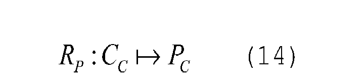
where if∀CCk ∃Pi ⇒ CCk = {P 1,...,Pn }
and given that CC = {C 1,...,Cn }, then:
- On the basis of what has been said, it is consequently possible to define some fundamental relations between the spaces involved in the process of standardization.
- In particular, defining the fundamental relation

j as the i-th test of the j-th specification, it may be deduced that
To demonstrate the truth of said definition we shall define the j-th specification as




- The above reasoning can be repeated in a similar way to demonstrate the relation that links the standards to the specifications and the relation that links the directives to the standards.
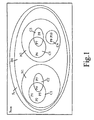
- What has been said so far can be illustrated graphically as shown in
Figure 1 , which regards a set representation of entities involved in a process of standardization. - Having introduced the entities involved in the process of type approval of an interconnected system, for a better understanding of the present invention, there is now described a preferred embodiment, purely by way of non-limiting example and with reference to the annexed plate of drawings, wherein:
-
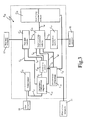
Figure 2 shows a flowchart corresponding to a method for determining the complexity of a process of type approval of an interconnected system, according to the present invention; and -
Figure 3 shows an example of interconnected system for which it is desired to determine the complexity of the process of type approval. - In particular, as shown by
block 100 ofFigure 2 , in order to be able to determine the degree of standardization complexity of an interconnected system it is first of all necessary to define the interconnected system SCE on the basis of Eq. (6), identifying the number and type of the components that form part thereof. - Recalling once again that the standardization of the system is proportional to the characteristics of SCE , and hence that the standardization of the system is a subspace of the standards, the process of standardization is not performed over the entire space but over the subspace generated by SCE on the basis of the reference operators R D , R N , R C and R P .
- Consequently, once the system SCE to be standardized has been defined as the set of components that form part thereof, in the case of an interconnected system it is necessary to take into consideration the link, i.e., the interconnection that exists between the various components of the system, as represented by
block 110 ofFigure 2 . - For this purpose, it is useful to define an operator of interconnection l equal to

- Eq. (21) states that there exists an operator lij called operator of interconnection that correlates two components of the system under examination.
- The importance of said operator lies in the fact that it enables description of the links that are present between the various components of the interconnected system without the need to detail the type of said links.
- For completeness of treatment the concept of space of the interconnections, i.e., the space of all the possible links between all the possible components, is introduced as

where L is the space of the interconnections. - On the basis of Eq. (22) it is thus possible to define an interconnected system as the system that comprises at least two components connected to one another. Consequently, if:


Formally, then, an interconnected system is a set of components and interconnections that can be expressed by the following notation:
where the superscript l indicates precisely the existence of links between the components CE of the system and hence the interconnection. - Once the number of interconnections between the components of the system has been established, the dimensions of the system are defined on the basis of the number of components that form part thereof and on the basis of the number of interconnections between the components (block 120).
In particular, the dimensions of the system are defined via an operator # of cardinality of the set

- In order to define more precisely the architecture of the system, rather than have a single index of the dimension of the system comprising blocks and interconnections, it is better to have two distinct indices:
-


- After defining the dimensions of the system, the specific functions performed by the system, as well as the functions performed by each component of the system are identified and defined in
block 130. - In particular, defined by SFi is a specific function to be performed by an interconnected system and by Fi is a function performed by a component of the system.
- If SFi is a specific function to be performed by the interconnected system under examination, then SSF, which is the set of the specific functions to be performed by the entire system, is defined as

- On the basis of Eq. (27) we therefore define as operative content Cop of an interconnected system the function that associates the set of the functions performed by the system:

- In particular, as may be noted from Eq. (28), the relation that links the operative content Cop with the set of the specific functions SSF to be performed by the system depends upon the functions performed by the individual components of the system. Consequently, defining by Fi a function performed by a component of the system, a function-link operator is defined as

- Eq. (29) allows us to introduce a wider concept, namely, the one regarding the function space Sf , which can be expressed by the equation:


- Since it is very likely for a component of the system to perform a number of functions, it is convienient to treat the function space as vector space and the series of functions performed by a component of the system as vector of the functions performed Vf .
- In particular, the vector of the functions performed Vf is equal to

where Fi assumes the value 0 if the component does not perform a specific function or else thevalue 1 if the component performs a specific function.
rom the consideration made on the function space Sf and from the definition of Eq. (32) we find that the space Sf is
where V f1 =(1,0...0),...,Vfn =(0...0,1) .
Consequently, V f1 = (1,0...0),...,Vfn = (0...0,1) is a base of the vector space Sf . - On the basis of what has been said so far, it is deduced that the overall functions performed by a single component CEi is the linear combination of the elements of the base of the vector space:

- We can now pass on to the entire interconnected system


- Consequently,

- On the basis of what has been said, it is possible then to define the self-consistency of the interconnected system


- From Eq. (36) it may be deduced that the system is self-consistent when the functions specified are a subset of the functions that the interconnected system is able to perform, i.e., of its operative content Cop.
- Now, as illustrated in
block 140 ofFigure 2 , it is necessary to identify the directives, standards, specifications, and tests involved in the process of standardization. - In particular, from an operative point of view, the entities involved in the process of standardization that require the largest amount of work and that present the greatest difficulties are the specifications and the tests.
- In this connection, it is very useful to gather the tests and specifications on the basis of the definition of test space SP , as defined in Eq. (5).
- In particular, for this purpose, we can interpret the space SP as a vector space where the individual test Pi is a vector comprising only a 1 in the i-th position and a plurality of 0's in the remaining positions. Consequently, if our test space has dimension n, then we shall find that

- In particular, given a specification made up of a number of tests, on the basis of Eq. (37) it is possible to state that a specification Ci is an appropriate linear combination of the tests Pi , namely,

- Starting from the consideration that Cc is the space of the specifications involved, i.e., a subspace of the specification space SC , if said space is considered as a vector space, then from Eq. (38) it may be inferred that the specifications Ci involved in the process of standardization are

where j ≤ n is the dimension of the space of the specifications. - Now, substituting in the expression (39) the expression of the specifications obtained from Eq. (38), we obtain a matrix that we shall call type-approval matrix, MS
CE .
- The matrix MS
CE , from the way in which we have defined the tests Pi and the specifications Ci involved, is a more or less sparse matrix, the elements of which are equal to 0 when a test is not to be carried out and equal to 1 when a test is to be carried out, and in which the rows represent the specifications involved and the columns represent the tests involved. - Now, as illustrated in
block 160, it is necessary to process the matrix MSCE , eliminating all the columns where only 0's appear, in so far as said columns are related to tests not concerning the system under examination and are consequently useless for type approval. - The type-approval matrix will be designated by MS
l CE in order to recall the fact that said matrix regards a particular interconnected system Sl CE . We recall in fact that the subscript CE indicates that the system is to be certified and that the superscript l indicates that the system under examination is of the interconnected type. A first consideration regards the operative importance that said matrix has in the process of standardization of an interconnected system. It enables in fact convenient identification of the tests to be carried out and of the specifications involved in the process of standardization and provides an indication of the complexity of the procedure of standardization, which depends directly upon the quantity of 1's present in the matrix. - On the basis of the type-approval matrix MS
l CE there is then determined the dimension of the standardization (block 170), which provides an indication of the amount of work that it is necessary to perform for certifying the system under examination. Recalling the characteristics of the type-approval matrix, i.e., Rows of MSl CE ∝ number of relevant specifications, Columns of MSl CE ∝ number of tests envisaged by a specification, the dimension DN of the standardization is defined as
- Eq. (41) expresses that the amount of work that it is necessary to perform for type approval corresponds to the maximum between the number of rows or columns of the type-approval matrix. The reason for this is that "many rows and few columns" means many specifications to be considered but few tests to be carried out and a consequent "large" amount of work in order to meet all the specifications. Considering likewise the case of "many columns and few rows", this means few specifications to be considered and to trace but with many tests to carry out or get carried out by a suitably qualified person: in this case there is an obvious and burdensome commitment for satisfying all the tests required.
- In particular, the dimension DN indicates only "how much" it is necessary to work for standardizing the system under examination, but does not provide any information regarding the "difficulty" of the process of standardization of the interconnected system under examination.
- To establish the standardization complexity, designated by CNS , it is necessary to make certain considerations. Intuitively, the complexity of standardization of the system depends to some extent upon the dimension of the system itself: the "larger" the system (made up of numerous subsystems and high level of articulation between them) and the higher the number of "differentiated" tests to be carried out, the higher the number of requirements and criteria to be met. We thus assume a relation that indicates the strict link between "complexity" (defined hereinafter) and dimension of the system, represented by the relation:

- However, it should be pointed out that the relation (42) is not completely correct, since a system could be made up of many components that are, however, the same as one another, in which case there would be an "extensive" system but a low amount of work for carrying out standardization thereof and hence also a lower degree of difficulty. It follows that the standardization complexity, rather than depending upon the dimension of the system to be standardized, depends upon the dimension of the standardization of the system itself.
- It is, consequently, necessary to find again a relation linked to the type-approval matrix MS
l CE . - More precisely, if the dimension of the standardization is represented by the maximum number of rows or columns of the type-approval matrix, the standardization complexity will be represented by the rank of said matrix. In fact, the rank represents the number of linearly independent rows or columns. In the case in point, it means, then, the degree of diversification of the tests to be carried out. Consequently, "many differentiated tests" means high "complexity" in the process of standardization of the system. Intuitively, a system could have a "large" dimension of the standardization but, since it hypothetically has components with similar characteristics, a low diversification of the tests and hence a low complexity of type approval. Instead, an interconnected system could have a low dimension of the standardization but a high diversification of the tests and hence a high complexity of type approval at the level of amount of work to be carried out.
- The standardization complexity of the system can then be defined by the equation:

where ρ(MSCE )is the rank of the matrix. - Once the standardization complexity of the system has been defined, it is necessary to analyse how the interconnection between the components of the system affects the process of standardization.
- For this purpose, defined in
block 190 is an operator of interconnection l | lij , defined as
- Said operator identifies the interconnection between two components but, given a system formed by many components, it is necessary to identify a way whereby it is possible to represent all the interconnections between all the possible components. For this purpose, the concept of interconnection matrix is introduced. The interconnection matrix is a square matrix with a number of rows and columns equal to the number of components of the interconnected system under examination. A number nij in the position ij indicates then the relation that exists between block i and block j. If nij is 0, it means that the two blocks do not have interconnections; if instead nij≥1, it means that the two blocks have 1 or n links of interconnection. Consequently, given the interconnected system

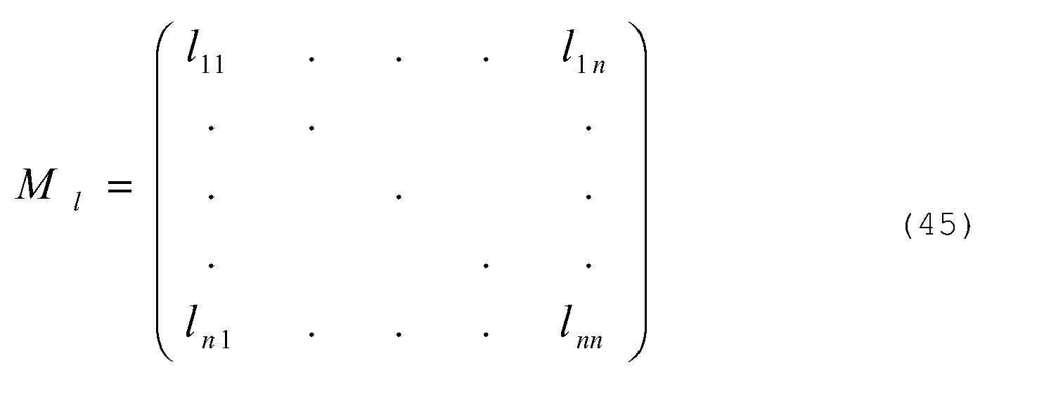
- As may be noted, all the numbers that appear within the matrix have the property n∈N. As has been defined, the matrix is always square and, consequently, if all the interconnections are considered as bidirectional (an assumption that is on the other hand valid in this treatment for the fact that it does not concern the mode of communication but only which blocks have a link), the matrix will be symmetrical with respect to the main diagonal (if the block i has n links with the block j, then the block j will have - bidirectionally - the same n links with the block i).
- Consequently, on the basis of the above considerations, the interconnection matrix can be rewritten in the following form:

- Taking now into consideration a single row k of said matrix, then, said row represents all the possible interconnections of the k-th system block. Thus defined as interconnection vector VCE
k of the block k is the k-th row of the interconnection matrix
- Consequently, the degree of interconnection Gint of the k-th block of the interconnected system is defined as

k , which represents how much the k-block of the interconnected system under examination is interconnected with the rest of the system itself.
Once the degree of interconnection Gint of each component of the system under examination is defined, inblock 200 the maximum degree of interconnectionG int(J) and minimum degree of interconnection G int(J) of the entire system are defined.
In particular, the maximum degree of interconnectionG int(J) is equal to
where J|G int K =G int(J) ⇒ J is the index of the component (k-th row) with the maximum degree of interconnection, whilst the minimum degree of interconnection G int(J) is equal to:
where I/G intK = G int(I)⇒I is the index of the component (k-th row) with the minimum degree of interconnection. - The maximum and minimum degrees of interconnection provide an indication as regards the complexity of the system. In fact, if the minimum degree of interconnection has a "high" value, then we shall have a "highly interconnected" system that has a complex architecture, instead, if the maximum degree of interconnection is a "relatively low" value, then our system will be a system that is "poorly interconnected" and hence quite simple.
- Once the maximum and minimum degrees of interconnection have been determined, in block 210 a quantity that indicates how many functions the system under examination is able perform is determined. In particular, said quantity is the degree Gfe of the functions performed by the system, defined as the norm of the vector Vf of the functions performed by the system:

- In order to be able to determine at least one quantity that will provide an indication of the complexity of the process of standardization of the interconnected system under examination, it is necessary to create a link between the quantities involved in the process of standardization so far introduced. For this purpose, defined in
blocks V CNS and a vector of architectural complexity VCAS of the system under examination. - In particular, the vector of standardization complexity
V CNS is defined on the basis of the dimension of the standardization DN and of the standardization complexity CNS
V CAS is defined on the basis of the number of the components of the system DCE, the number of the interconnections of system D int and of the maximum degree of interconnectionG int(J) and minimum degree of interconnection G int(J) of the system
- On the basis of the vector of standardization complexity
V CNS, inblock 240 the degree GCNS of standardization complexity of the system under examination is then determined. Said quantity is determined as the norm of the vector of standardization complexityV CNS
- In addition to the degree of standardization complexity GCNS of the system under examination, it is possible to determine in a similar way a further quantity that provides an indication as regards the complexity of the process of standardization of the interconnected system under examination, i.e., the degree GCAS of architectural complexity of the system, which is determined as the norm of the vector of architectural complexity
V CAS:
- As may be noted from Eqs. (54) and (55), the degree GCNS of standardization complexity and the degree GCAS of architectural complexity are simply numbers, which, in order to be able to provide useful information on the complexity of the process of standardization of the interconnected system under examination must necessarily be compared with reference values, such as for example pre-set normed values, or else values calculated for an interconnected system that is equivalent from the functional standpoint to the one being examined, obtained by substituting one or more components in the interconnected system under examination.
- In particular, it is possible to obtain an indication with high information content as regards the complexity of the process of verification of the normative compliance of an interconnected system by comparing with one another the respective degrees GCNS of standardization complexity and degrees GCAS of architectural complexity calculated for configurations different from the architectural standpoint but equivalent from the functional standpoint of the interconnected system for which it is desired to obtain type approval.
- On the basis of the theoretical-mathematical treatment described above, the method of the present invention is described hereinafter with reference to an interconnected system for the cogeneration of electrical energy and heat, as illustrated in
Figure 3 , without this implying any loss of generality. - In particular, designated by SCE in
Figure 3 is an interconnected system for cogeneration of electrical energy and heat comprising: a compressor CE1, a high-pressure internal-combustion engine CE2, an electric motor CE3, an electric subsystem CE4 , a thermal module CE5, a telematic module CE6, a supervision-and-control module CE7 , and an auxiliary module CE8 for the accumulation of electrical energy, for example, batteries. - In particular, the compressor CE1 is connected to a gas-
supply network 10 and is interconnected via an interconnection line l12 with the internal-combustion engine CE2 which is in turn connected to the electric motor CE4 via an interconnection line l24 , to the thermal module CE5 via an interconnection line l25 , and to the supervision-and-control module CE6 via an interconnection line l26. The electric motor CE4 is connected to the electric subsystem CE3 (for example, a transformer) via an interconnection line l43 , to the thermal module CE5 via an interconnection line l45 , to the supervision-and-control module CE6 via an interconnection line l46. - The electric subsystem CE3 is connected to a
electrical network 11, external to the system S CE , to which it supplies the electrical energy produced by the cogeneration system S CE . In particular, the electric subsystem CE3 is connected to the supervision-and-control module CE6 via an interconnection line l36 and to the auxiliary module CE8 for the accumulation of electrical energy via an interconnection line l38. - Furthermore, the supervision-and-control module CE6 is connected to the thermal module CE5 via an interconnection line l65, to the telematic module CE7 via an interconnection line l67, and to the auxiliary module CE8 for the accumulation of electrical energy via an
interconnection line 168. - The thermal module CE5 is in turn connected to a
thermal network 12, external to the system S CE , to which it supplies the thermal energy produced by the cogeneration system S CE .
The telematic module C E7 is in turn connected to atelecontrol system 13 through which remote control of the system S CE is possible. - As described in the theoretical-mathematical treatment, for determining the complexity of the process of standardization of the system of
Figure 2 , it is first of all necessary to define the system S CE on the basis of its components, i.e., in the case of the system S CE ofFigure 2 : - the compressor CE1
- the internal-combustion engine CE2,
- the electric motor CE3,
- the electric subsystem CE4,
- the thermal module CE5,
- the telematic module CE7 ,
- the supervision-and-control module CE6 , and
- the auxiliary accumulation module CE8.
- Consequently, the system SCE is given by

- After having defined the system S CE , the number of interconnections between the components of the system S CE is identified, and the interconnections are grouped together so as to form the expression (22).
- In particular, as emerges from
Figure 2 , the system S CE has twelve connections, i.e.,: l12 , l25 , l45 , l46 , l26 , l36 , l24 , l43, l38 , l65 , l68 , l67.
Grouping together the twelve interconnections identified in Eq. (6) we obtain:
- On the basis of the expression (22), it is possible then to determine the dimensions of the system SCE . In particular, since the components of the system S CE are eight and the interconnections between them are twelve, it follows that the dimension Dim of the system SCE is


- After the dimensions Dim of the system S CE have been defined, the specific functions to be performed by the interconnected system S CE are identified, as well as its operative content Cop.
- In particular, the cogeneration system S CE of
Figure 2 performs two specific functions; namely: - a function SF 1 corresponding to the supply of electrical energy in the network or to the loads; and
- a function SF 2 corresponding to the supply of thermal energy, for example hot water for canteen and heating purposes.
- Consequently, the set of the specific functions to be performed by the system can be summed up in the expression

- Furthermore, by analysing the cogeneration system SCE under examination, the following functions performed within it by the interaction of its components may be identified:
- production of mechanical energy: F1
- production of thermal energy: F2
- production of electrical energy: F3
- supervision and control of the components: F4
- accumulation of electrical energy: F5
- From a comparison between S SF and the operative content Cop , it emerges that, since the functions S F1 and S F2 are a subset of the functions F1, F2, F3, F4 and F5 that the interconnected system is able to perform, i.e., of its operative content


- At this point, applying the reference operators, the directives DC, the standards NC, the specifications CC, and the tests PC involved in the procedure of type approval of the system S CE are identified.
- In particular, the directives DC involved (RD : SCE ↦ DC) are:
- DC: {Machine directive 98/37, Low-voltage directive 73/23, EMC directive 89/336, PED directive 97/23}
Consequently, if we call:- D1 : Machine directive 98/37,
- D2 : Low-voltage directive 73/23,
- D3 : EMC directive 89/336, and
- D4 : PED directive 97/23;
- we find that

- NC:{UNI EN 292-1 Standard, UNI EN 292-2 Standard, UNI EN ISO 3477:1977 Standard, ISO 8528-10:1998 Standard, UNI EN ISO 1076:1999 Standard, Internal test procedure, Engine type approval according to 88/77/EEC Directive to 2001/27/EC Directive, ISO 8178-4 Standard, EN 60204-1 Standard, CEI 44-5, CEI 64-8, EN 55011 (1999), EN 61000-4-2 (1996), EN 61000-4-6 (1997)}
- Consequently, if we call:
- N1 : UNI EN 292-1 Standard,
- N2 : UNI EN 292-2 Standard,
- N3 : UNI EN ISO 3477:1977 Standard,
- N4 : ISO 8528-10:1998 Standard,
- N5 : UNI EN ISO 1076:1999 Standard,
- N6 : Internal test procedure,
- N7 : Engine type approval according to 88/77/EEC Directive to 2001/27/EC Directive,
- N 8: ISO 8178-4 Standard,
- N9 : EN 60204-1 Standard,
- N10 : CEI 44-5,
- N11 : CEI 64-8,
- N12 : EN 55011 (1999),
- N13 : EN 61000-4-2 (1996),
- N14 : EN 61000-4-6 (1997),
- we obtain

- The specifications CC involved (RC : NC ↦ CC ) are instead:
- CC:{Acoustics, vibrations, Exhaust-gas emissions, Safety, Electrical equipment/system, EMC}
Consequently, if we call- C1: Acoustics,
- C2 : Vibrations,
- C3 : Exhaust-gas emissions,
- C4 : Safety,
- C5 : Electrical equipment/system,
- C6 : EMC,
- we obtain

- The tests PC involved (RP :CC ↦ PC ) (derived from the Standards NC and from the Specifications CC ) are instead:
- P1: UNI EN ISO 3477:1977 Standard corresponding to:
- Acoustics - Determination of the levels of sound power of the sources of noise by means of sound pressure and technical method of design in a basically free field on a reflecting plane;
- P2: ISO 8528-10:1998 Standard corresponding to:
- Reciprocating internal-combustion engines coupled to alternators for the generation of electrical energy. Part 10:
- Measurement of the noise dispersed in the air through the method with envelope surface;
- Reciprocating internal-combustion engines coupled to alternators for the generation of electrical energy. Part 10:
- P3 : UNI EN ISO 1076:1999 Standard corresponding to:
- Mechanical vibrations - Tests on fixed machines for determining the emissions of the vibrations transmitted to the entire body;
- P4 : Internal test procedure, corresponding to:
- Internally established test with corresponding results;
- P5: Engine type approval according to 88/77/EEC Directive to 2001/27/EC Directive, corresponding to:
- Test cycles for CE type approval;
- P6: ISO 8178-4 Standard, corresponding to:
- Reciprocating internal-combustion engines, Measurement of exhaust emissions, Test cycles for different applications of the engines.
- P7: EN 55011 (1999), corresponding to:
- Emissions conducted in a.c. from 150 kHz to 30 MHz (industrial environment);
- P8: EN 61000-4-2 (1996) corresponding to:
- Immunity to the electrostatic discharge (ESD);
- P9 : EN 61000-4-6 (1997) corresponding to:
- Immunity to conducted disturbance, induced by radiofrequency fields (injection of common-mode RF current);
- P10: UNI EN 292-1 Standard, UNI EN 292-2 Standard, EN 60204-1, CEI 44-5, CEI 64-8, corresponding to technical verifications.
- P4 : Internal test procedure, corresponding to:
- In this way we obtain




- By organizing the specifications from C1 to C6 in the type-approval matrix MS
CE we obtain:
- Eliminating from the type-approval matrix MS
CE the columns of just zeros we obtain:
- From the type-approval matrix MS
CE it is possible to obtain - the dimension DN of the standardization, namely,

CE ; and - the standardization complexity CNS :

CE . - After the dimension DN and the complexity CNS of the standardization have been determined, the interconnection matrix M1 is determined, which, we recall, is a square matrix with a number of rows and columns equal to the number of components of the interconnected system under examination, i.e.,

- From the interconnection matrix M1 we obtain the following interconnection vectors for each component of the system SCE:



- For each of the vectors listed above there is then calculated the respective degree of interconnection of the component, i.e.,




- On the basis of the degrees of interconnection calculated above, the maximum degree of interconnection
G int(J) and minimum degree of interconnection G int(J) are then determined, namely,
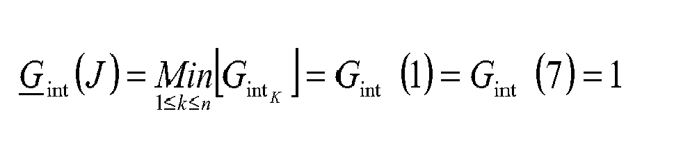
- the supervision-and-control module CE6, which is thus the component of the system SCE with the largest number of interconnections; and
- the compressor CE1 and the telematic module CE7 , which, as may be noted from
Figure 2 , are the components of the system with the smallest number of interconnections. - On the basis of the maximum degree of interconnection and minimum degree of interconnection the degree Gfe of the functions performed by the system is determined, defined as the norm of the vector Vf of the functions performed by the cogeneration system, namely,

- Consequently, the vector of standardization complexity VCNS and the vector of architectural complexity
V CAS are equal to


- As discussed at the end of the theoretical-mathematical treatment, the degree GCNS of standardization complexity and the degree GCAS of architectural complexity calculated for the cogeneration system under examination provide useful information on the complexity of the process of standardization of the cogeneration system only if compared with reference values.
- Consequently, in order to obtain said reference values, there will be hereinafter calculated the degree GCNS of standardization complexity and the degree GCAS of architectural complexity of a plurality of systems similar to that of
Figure 2 from the functional standpoint, i.e., with the same operative content, but with some different components CE . - We shall suppose, for example, substituting in the system SCE of
Figure 2 the auxiliary module CE8 for accumulation of electrical energy with a fly-wheel. Said substitution would require the modification of some specifications CC involved in the process of standardization, in so far as it would no longer be necessary to carry out the tests of a chemical type of the batteries, which would be replaced by tests of a vibroacoustic, structural and mechanical type necessary for testing the functionality of the fly-wheel. - Consequently, to take into account said difference it is necessary to modify the type-approval matrix, which consequently assumes the form:


- The above modification thus has an effect not on the dimension Dim of the system or on the architecture or the degree of functionality of the cogeneration system, but only on the dimension DN and on the complexity CNS and the standardization, the values of which consequently become


- Consequently, the vector of standardization complexity VCNS and the vector of architectural complexity VCAS , become respectively


- Comparing the values of the degree GCNS of standardization complexity and of the degree GCAS of architectural complexity calculated for the cogeneration system of
Figure 2 with the ones obtained by replacing the auxiliary module CE8 for the accumulation of electrical energy with a fly-wheel, it may be noted how those corresponding to the system with the fly-wheel are higher than those of the system with the auxiliary accumulation module CE8, which consequently is less complex from the standpoint of the standardization as compared to that with the fly-wheel. This is due to the fact that the system with the fly-wheel entails a larger number of tests to be carried out as compared to the ones necessary for standardization of the system with the auxiliary accumulation module CE8. - From the above comparison it clearly emerges how the choice of one component instead of another, given the same operative content and degree of architectural complexity, considerably affects the process of standardization of an interconnected system as regards its complexity.
- As has been described, we shall suppose, for example, substituting in the system SCE of
Figure 2 the high-pressure internal-combustion engine CE2 with a low-pressure engine that does not entail the use of the compressor CE1, which can thus be eliminated from the system SCE ofFigure 2 . - In this case, the modification made affects the dimension Dim of the system and its degree of interconnection Gint, but the tests to be carried out would remain substantially the same.
- Consequently, the vector of standardization complexity VCNS and the vector of architectural complexity VCAS become respectively


- Comparing said results with those obtained for the system SCE with the compressor CE1, it may be noted how the architectural complexity of the system without compressor is obviously smaller than that with the compressor, but the standardization complexity of the two systems has remained unvaried.
- In the case where in the system of
Figure 2 there were to be eliminated the compressor CE1 , the high-pressure internal-combustion engine CE2 were to be replaced with a low-pressure engine, and the auxiliary accumulation module CE8 were to be replaced with a fly-wheel, there would be obtained a vector of standardization complexityV CNS and a vector of architectural complexityV CAS equal to


- We shall now suppose, for example, adding to the system SCE of
Figure 2 two further components, such as, for example, a heat pump connected to the thermal module CE5 and a thermal-accumulation device connected to the heat pump. - To obtain type approval of the aforesaid system, in addition to the execution of the tests corresponding to the system of
Figure 2 , it is necessary to carry out further safety and chemical tests. Furthermore, the presence of the heat pump and of the system of thermal accumulation modify the degree of functionality of the system under examination since they add to the system the functions performed by the new components, namely: - the production of cold, and
- thermal accumulation.
- Consequently, for the aforesaid system configuration, the vector of standardization complexity
V CNS and the vector of architectural complexityV CAS become, respectively



- In the case where, once again by way of example, in addition to adding the heat pump and the thermal-accumulation device, in the system SCE of
Figure 2 the compressor CE1 is eliminated, the high-pressure internal-combustion engine CE2 is replaced with a low-pressure engine, and the auxiliary accumulation module CE8 is replaced with a fly-wheel, the vector of standardization complexityV CNS and the vector of architectural complexityV CAS become, respectively


- Thanks to the method of the present invention it is possible to optimize the design of an interconnected system in so far as, through the determination of the degree GCNS of standardization complexity and of the degree GCAS of architectural complexity, it is possible both to obtain a rough indication of the complexity of the process of verification of the normative compliance of the interconnected system that is to be designed and type-approved and to evaluate different system configurations in order to simplify, wherever possible, said process of verification and reduce the costs linked thereto.
- Finally, it is clear that modifications and variations can be made to the method described and illustrated herein, without thereby departing from the sphere of protection of the present invention, as defined in the annexed claims.


Consequently, we obtain:

In particular, if the space PC of the tests is considered as vector space, we obtain:


For this purpose, the tests that form part of the specification involved are distinguished by 1, and those that do not form part thereof are distinguished by 0.
Claims (6)
- A method for determining the complexity of a process of type approval of an interconnected system (SCE ), characterized in that it comprises:- defining a mathematical formalism that links architectural and functional characteristics of said interconnected system (SCE) to criteria of type approval defined in at least one standard; and- determining a quantity (GCNS , GCAS ) that provides an indication of the complexity of said process of type approval on the basis of said mathematical formalism.
- The method according to Claim 1, wherein said interconnected system comprises a plurality of components (CE) interconnected to one another and each designed to perform a function of a technical type and wherein defining said mathematical formalism comprises:- determining the number of said components (CE) forming part of said interconnected system (SCE );- determining the number of interconnections (ln ) between said components (CE) of said interconnected system (SCE );- determining a quantity (Dim) indicating the dimensions of said interconnected system (SCE) on the basis of said number of components(CE) and of said number of interconnections (ln );- determining the number of functions (SFn ) performed by said interconnected system and the number of functions (Fn) performed by each component of said interconnected system;- identifying a standard (Nc ) and at least one specification (Cc ), which forms part of said standard (Nc ) and defined in which are technical tests (Pc ) that it is necessary to carry out on each of said components (CE) and on said system (SCE) in order to verify whether said components (CE) and said system (SCE) meet given criteria of type approval;- determining on the basis of said standard the number of specifications (CC ), defined in which are said criteria of type approval that must be met by each of said components (CE) and said system (SCE), and the number of said tests (PC ) to be carried out on each of said components (CE) and on said system (SCE );- determining a type-approval matrix (MS
CE ) containing said number of specifications (CC ) and said number of said tests (PC );- processing said type-approval matrix (MSCE ) ;- determining, on the basis of said type-approval matrix (MSCE ), a quantity (DN ) indicating an amount of work that it is necessary to perform for carrying out said process of type approval;- determining, on the basis of said type-approval matrix, a quantity (CNS) indicating the complexity of said amount of work that it is necessary to perform for carrying out said process of type approval; and- determining said quantity (GCNS ) that provides an indication of the complexity of said process of type approval on the basis of said quantity (DN ) indicating an amount of work that it is necessary to perform for carrying out said process of type approval and of said quantity (CNS) indicating the complexity of said amount of work that it is necessary to perform for carrying out said process of type approval. - The method according to Claim 2, wherein:- said type-approval matrix (MS
CE ) comprises a number of rows equal to said number of said specifications (CC ) and a number of columns equal to said number of said tests (PC ) ;- said quantity (DN ) indicating an amount of work that it is necessary to perform for carrying out said process of type approval corresponds to said number of rows;- said quantity indicating the complexity of said amount of work that it is necessary to perform for carrying out said process of type approval is determined on the basis of the rank of said type-approval matrix; and- said quantity (CNS ) that provides an indication of the complexity of said process of type approval is determined on the basis of the norm of said number of rows and of said rank of said type-approval matrix. - The method according to Claim 2, wherein defining said mathematical formalism moreover comprises:- determining an interconnection matrix (M1 ) containing said number of components (CE) of said interconnected system (S CE ) and said number of interconnections (ln ) between said components (CE) of said interconnected system (S CE ); and- determining a quantity (
G int(J)) indicating a maximum degree of interconnection between said component s(CE) of said interconnected system (S CE ) and a quantity ( G int(J)) indicating a minimum degree of interconnection between said components (CE) of said interconnected system (S CE ) on the basis of said interconnection matrix (M1 ). - The method according to Claims 1, 2 and 4, wherein said quantity (GCAS ) that provides an indication of the complexity of said process of type approval is determined on the basis of said number of said components (CE) forming part of said interconnected system, of said number of interconnections (ln) between all the components (CE) of said system (SCE ), of said quantity ( G int(J)) indicating a maximum degree of interconnection between said components of said system and of said quantity ( G int(J)) indicating a minimum degree of interconnection between said components of said system.
- The method according to Claim 5, wherein said quantity (GCAS ) that provides an indication of the complexity of said process of type approval is determined on the basis of the norm of said number of said components (CE) forming part of said interconnected system, of said number of interconnections (ln ) between all the components (CE) of said system (S CE ), of said quantity (G int(J)) indicating a maximum degree of interconnection between said components of said system, and of said quantity (G int(J)) indicating a minimum degree of interconnection between said components of said system.
Priority Applications (1)
| Application Number | Priority Date | Filing Date | Title |
|---|---|---|---|
| EP20070425070 EP1956537A1 (en) | 2007-02-07 | 2007-02-07 | Method for determining the complexity of a process of type approval of an interconnected system |
Applications Claiming Priority (1)
| Application Number | Priority Date | Filing Date | Title |
|---|---|---|---|
| EP20070425070 EP1956537A1 (en) | 2007-02-07 | 2007-02-07 | Method for determining the complexity of a process of type approval of an interconnected system |
Publications (1)
| Publication Number | Publication Date |
|---|---|
| EP1956537A1 true EP1956537A1 (en) | 2008-08-13 |
Family
ID=38115709
Family Applications (1)
| Application Number | Title | Priority Date | Filing Date |
|---|---|---|---|
| EP20070425070 Withdrawn EP1956537A1 (en) | 2007-02-07 | 2007-02-07 | Method for determining the complexity of a process of type approval of an interconnected system |
Country Status (1)
| Country | Link |
|---|---|
| EP (1) | EP1956537A1 (en) |
-
2007
- 2007-02-07 EP EP20070425070 patent/EP1956537A1/en not_active Withdrawn
Non-Patent Citations (1)
| Title |
|---|
| No Search * |
Similar Documents
| Publication | Publication Date | Title |
|---|---|---|
| CN109270919B (en) | A kind of vehicle detection data managing method, analysis method, equipment and server | |
| Helton | Conceptual and computational basis for the quantification of margins and uncertainty | |
| CN112115553B (en) | Vehicle electromagnetic compatibility simulation method, device, storage medium and apparatus | |
| Chen et al. | A multi‐attribute reliability allocation method considering uncertain preferences | |
| Zhang et al. | Evaluation of demand response resource aggregation system capacity under uncertainty | |
| Sterling et al. | Model-based fault detection and diagnosis of air handling units: A comparison of methodologies | |
| Ruddle et al. | Adapting automotive EMC to meet the needs of the 21st century | |
| CN115951292A (en) | An online evaluation method and device for the error state of an electronic voltage transformer | |
| Liu et al. | Integrated power transformer diagnosis using hybrid fuzzy dissolved gas analysis | |
| Baier et al. | Simulation for continuous-time Markov chains | |
| Jensen et al. | Design of an electrical power system using a functional failure and flow state logic reasoning methodology | |
| Woodcock et al. | The steam boiler in a unified theory of Z and CSP | |
| CN103196691B (en) | Method for establishing relevance fault testing matrix based on main diagonal element domination fuzzy relation matrix | |
| Nyberg et al. | Model based diagnosis of the air path of an automotive diesel engine | |
| Mu et al. | Application of ARIMA model in fault diagnosis of TEP | |
| CN109902006A (en) | Automated testing method and device | |
| CN116653621B (en) | Relay drive control device, method, equipment, storage medium and vehicle | |
| CN120105743A (en) | An intelligent testability design system and method for avionics equipment based on Matlab-Simulink joint model | |
| CN111625753A (en) | Method, device and equipment for calculating energy efficiency parameter of direct combustion engine and storage medium | |
| CN117856940A (en) | Interference test method, device, computer equipment and storage medium | |
| Lu et al. | Electromagnetic interference effect assessment under measuring testability limitation based on physics-informed neural network and Gaussian process regression | |
| CN121503236A (en) | Power plant remote simulation methods and devices, electronic equipment, and storage media | |
| CN118971914B (en) | Method and system for testing transmission performance of vehicle-mounted Ethernet cable harness | |
| CN121257134B (en) | A test simulation device and method for simulating electrical load. | |
| Torta et al. | Automatic component abstraction for Model-Based Diagnosis on relational models |
Legal Events
| Date | Code | Title | Description |
|---|---|---|---|
| PUAI | Public reference made under article 153(3) epc to a published international application that has entered the european phase |
Free format text: ORIGINAL CODE: 0009012 |
|
| 17P | Request for examination filed |
Effective date: 20080429 |
|
| AK | Designated contracting states |
Kind code of ref document: A1 Designated state(s): AT BE BG CH CY CZ DE DK EE ES FI FR GB GR HU IE IS IT LI LT LU LV MC NL PL PT RO SE SI SK TR |
|
| AX | Request for extension of the european patent |
Extension state: AL BA HR MK RS |
|
| 17Q | First examination report despatched |
Effective date: 20080814 |
|
| AKX | Designation fees paid |
Designated state(s): AT BE BG CH CY CZ DE DK EE ES FI FR GB GR HU IE IS IT LI LT LU LV MC NL PL PT RO SE SI SK TR |
|
| STAA | Information on the status of an ep patent application or granted ep patent |
Free format text: STATUS: THE APPLICATION IS DEEMED TO BE WITHDRAWN |
|
| 18D | Application deemed to be withdrawn |
Effective date: 20120901 |