EP1956271A1 - Automatic transmission - Google Patents
Automatic transmission Download PDFInfo
- Publication number
- EP1956271A1 EP1956271A1 EP06823153A EP06823153A EP1956271A1 EP 1956271 A1 EP1956271 A1 EP 1956271A1 EP 06823153 A EP06823153 A EP 06823153A EP 06823153 A EP06823153 A EP 06823153A EP 1956271 A1 EP1956271 A1 EP 1956271A1
- Authority
- EP
- European Patent Office
- Prior art keywords
- output shaft
- shaft
- ball bearing
- input shaft
- side face
- Prior art date
- Legal status (The legal status is an assumption and is not a legal conclusion. Google has not performed a legal analysis and makes no representation as to the accuracy of the status listed.)
- Granted
Links
Images


Classifications
-
- F—MECHANICAL ENGINEERING; LIGHTING; HEATING; WEAPONS; BLASTING
- F16—ENGINEERING ELEMENTS AND UNITS; GENERAL MEASURES FOR PRODUCING AND MAINTAINING EFFECTIVE FUNCTIONING OF MACHINES OR INSTALLATIONS; THERMAL INSULATION IN GENERAL
- F16H—GEARING
- F16H57/00—General details of gearing
- F16H57/02—Gearboxes; Mounting gearing therein
- F16H57/021—Shaft support structures, e.g. partition walls, bearing eyes, casing walls or covers with bearings
-
- Y—GENERAL TAGGING OF NEW TECHNOLOGICAL DEVELOPMENTS; GENERAL TAGGING OF CROSS-SECTIONAL TECHNOLOGIES SPANNING OVER SEVERAL SECTIONS OF THE IPC; TECHNICAL SUBJECTS COVERED BY FORMER USPC CROSS-REFERENCE ART COLLECTIONS [XRACs] AND DIGESTS
- Y10—TECHNICAL SUBJECTS COVERED BY FORMER USPC
- Y10T—TECHNICAL SUBJECTS COVERED BY FORMER US CLASSIFICATION
- Y10T74/00—Machine element or mechanism
- Y10T74/21—Elements
- Y10T74/2186—Gear casings
Definitions
- the present invention relates to an automatic transmission, for example, that is mounted in a vehicle, more specifically, the present invention relates to an automatic transmission whose input shaft and output shaft of a speed change mechanism structure a single-shaft aligned center axis and which has a lock-up clutch on the input shaft.
- a torque converter coaxially arranged between an output shaft (a crankshaft) of the engine and a propeller shaft transmitting rotation to rear wheels in the vehicle, and connected to the output shaft of the engine, and a speed change mechanism shifting a rotation of the torque converter and transmitting the rotation to the propeller shaft, are aligned on the same one shaft.
- the input shaft and the output shaft are rotatably fitted directly or via an intermediate shaft, and a single-shaft aligned center axis is structured by the shaft in a both-end support state by a case, a gear mechanism including rotary members such as each gear of planetary gears, a hub member connecting these gears, a sleeve member, a (clutch) drum member, and the like is arranged about the center axis.
- rotary members except for what are fixed on the center axis (the input shaft, the intermediate shaft, and the output shaft) are rotatably supported on the center axis by a sleeve or a needle bearing and the like and also supported for the axial direction by a thrust bearing and the like interposed among each rotary members.
- the propeller shaft generates torsion because a rotational torque acts when it transmits driving rotation.
- the changes of torsion magnitude by torque variation cause expansion and contraction. Therefore, for example, pressing force and tensile force are applied, to the output shaft fixed in the propeller shaft via a flange yoke and the like from the axially rear side.
- pressing force and tensile force are applied, to the output shaft fixed in the propeller shaft via a flange yoke and the like from the axially rear side.
- the output shaft is pressed from the rear side and moves to the front side, there is a possibility that the input shaft moves via a thrust bearing and the like interposed among the rotary members.
- the torque converter provided with a lock-up clutch is affected on the axial position of the lock-up clutch, so there are possibilities that a slip occurs at the time of non-engagement, and a controllability in an engagement control (a slip control) is adversely affected.
- an object of the present invention to provide an automatic transmission capable of enhancing durability and compactness of a ball bearing, while supporting an axial position of an output shaft with high accuracy.
- an automatic transmission (1) including a case (2), a speed change mechanism (3) including an input shaft (4) and an output shaft (6), the two shafts being rotatably supported for the case (2) and forming a single-shaft aligned center axis (3A), and arranging a gear mechanism (3B) on the center axis (3A), and a torque converter (10) having a lock-up clutch (20) arranged axially (indicated by X1-X2) freely slidably toward and away from the input shaft (4), the case (2) including a sleeve unit (2d) coating the outer periphery of the output shaft (6), the output shaft (6) including a flange unit (6a) arranged opposite a side face (2g) of the sleeve unit (2d) on the axially input shaft side (indicated by X1), the sleeve unit (2d) having a first
- a thrust bearing is interposed between the flange unit and the side face of the sleeve unit at the axially input shaft side
- the ball bearing is interposed between the inner periphery of the sleeve unit and the outer periphery of the output shaft so that the side face of the outer race of the ball bearing to be contacted with the first step portion toward the axially input shaft side
- the propeller shaft connecting members can be connected with the propeller shaft, and spline-engaged with the outer periphery of the output shaft, and the propeller shaft connecting members contact the side face of the inner race of the ball bearing upon being pressed axially toward the input shaft by the propeller shaft.
- the thrust bearing can receive such force.
- the ball bearing can receive such force.
- the force occurring on the ball bearing is made only to the force acting axially toward the input shaft. This not only improves durability and compactness of the ball bearing, but also prevents the lock-up clutch from getting affected by expansion and contraction of the propeller shaft.
- a precise size including the product size deviations can be measured from outside the case of the ball bearing, and the shape of the propeller shaft connecting members according to the size can be optimized. As a result, the measurement can be made easier and also an increase in production process is prevented.
- the output shaft (6) has a second step portion (6c) provided opposite (indicated by X2) the axially input shaft side relative to the ball bearing (60) on the outer periphery (6e), and abutting toward the axially input shaft side (indicated by X1)
- the propeller shaft connecting members (7, 8) have a contact portion (8b) contacting the second step portion (6c), and an extension portion (8a) extending toward an outer periphery of the second step portion (6c)
- the output shaft (6) further includes a fastening member (9) fastening the propeller shaft connecting members (7, 8), toward the axially input shaft side (indicated by X1), to the second step portion (6c) via the contact portion (8b), and the extension portion (8a) contacts the side face (62a) of the inner race (62) of the ball bearing (60) upon being pressed axially toward the input shaft side (indicated by X1) by the propeller shaft.
- the propeller shaft connecting members are fastened, toward the axially input shaft side, to the second step portion via the contact portion by the fastening member, and the extension portion contacts the side face of the inner race of the ball bearing upon being pressed axially toward the input shaft by the propeller shaft. Accordingly, the propeller shaft connecting members can be fixed on the output shaft, and also the ball bearing can receive pressing force upon being pressed by the propeller shaft.
- the extension portion (8a) when not pressed axially toward the input shaft side (indicated by X1) by the propeller shaft, shares with the side face (62a) of the inner race (62) of the ball bearing (60) an empty space (d) which is smaller than a clearance (such as c42) in the axial direction (indicated by X1-X2) possessed in the speed change mechanism (3).
- the extension portion when not pressed axially toward the input shaft by the propeller shaft, shares with the side face of the inner race of the ball bearing an empty space which is smaller than a clearance in the axial direction possessed in the speed change mechanism.
- the output shaft moves to the extent of the empty space, so that the ball bearing can receive the pressing force. The movement of the output shaft is absorbed in the speed change mechanism, enabling to prevent the lock-up clutch from being affected by pressure applied by the propeller shaft.
- the input shaft (4) and the output shaft (6) are loosely fitted in the axial direction (indicated by X1-X2), and a plurality of rotary members in the gear mechanism (3) are rotatably supported by a plurality of thrust bearings (such as 42) in the axial direction (indicated by X1-X2), and the clearance in the axial direction (indicated by X1-X2) possessed in the speed change mechanism (3) is the sum total of clearances (such as c42) between a plurality of rotary members in the gear mechanism (3B) and a plurality of thrust bearings (such as 42).
- the clearance in the axial direction which the speed change mechanism has can be determined by the sum total of the clearances between the plurality of rotary members in the gear mechanism and the plurality of thrust bearings.
- the propeller shaft connecting members include a shimwasher (8) integrally formed with the contact portion (8b) and the extension portion (8a), and a flange yoke (7) having a flange unit (7a) connected with the propeller shaft and a boss unit (7b) which is spline-engaged (6s, 7s) with the output shaft (6), and the extension portion (8a) of the shimwasher (8) is provided with a length (L2) so as to form the empty space (d) according to a distance (L1) between the side face (62a) of the inner race (62) of the ball bearing (60) and the second step portion (6c).
- the propeller shaft connecting members include the shimwasher integrally formed with the contact portion and the extension portion, and the flange yoke having the flange unit connected with the propeller shaft and the boss unit spline-engaged with the output shaft.
- the extension portion of the shimwasher is provided with a length so as to form the empty space according to the distance measured between the side face of the inner race of the ball bearing and the second step portion.
- extension portion and the contact portion are formed separately, for example, there is a possibility for the extension portion to be assembled erroneously between the second step portion and the contact portion. However, such an erroneous assembly is prevented because the contact portion and the extension portion of the shimwasher are integrally formed.
- the shimwasher (8) is selected and applied that has a length equal to the length of the extension portion (8a).
- the shimwasher is selected and applied that has a length equal to the length of the extension portion to form the empty space. This eliminates the need to process the shimwasher for each product individually, enabling to form the empty space with high accuracy.
- the case (2) is integrally formed with a transmission case unit (2B) encasing the speed change mechanism (3), and the sleeve unit (2d).
- the case is integrally formed with the transmission case unit including the speed change mechanism, and the sleeve unit.
- measurement including the product size deviations inside of the case for the ball bearing is not easy, and also assembling parts (a washer and the like) with high accuracy according to the measurement causes an increase in production process.
- measurement including the product size deviations outside the case for the ball bearing can easily be performed, and an increase in production process such as detaching and reassembling the ball bearing is prevented.
- FIG. 1 An automatic transmission shown in FIG. 1 according to the present invention is preferably used for a vehicle of the FR type.
- the left side indicated by X1 is the front side for the vehicle, and, the right side indicated by X2 is the rear side. Therefore the left in the figure is referred as the "front side”, and the right side is referred as the "rear side”.
- an automatic transmission 1 is preferably used for a vehicle of the FR type. Roughly from the front side to the rear side, the automatic transmission 1 includes a torque converter 10 having a lock-up clutch 20, and a speed change mechanism 3 in an integrated case (simply referred to as a "case", hereinafter) 2 having a housing case unit 2A, a transmission case unit 2B, and an end case C.
- the torque converter 10 is included in the housing case unit 2A (and an engine case)
- the speed change mechanism 3 is included in the transmission case unit 2B
- a partition wall member 2b fixed in a portion on the front side of the transmission case unit 2B and a partition wall member 2c at the rear side.
- the torque converter 10 is housed in the housing case unit 2A, and is arranged on the input shaft 4 of the speed change mechanism 3, which is described in detail below, and is interposed between an input shaft 11 as the automatic transmission 1 connected to an output shaft (a crankshaft) of the engine, not shown, and the input shaft 4 of the speed change mechanism 3 as a transmission path.
- the torque converter 10 has a front cover 12 and a rear cover 13 that are integrally coupled by welding or the like.
- the front cover 12 is connected to the output shaft of the engine via the input shaft 11.
- the rear cover 13 its outside diameter unit forms an outer contour of a pump impeller 13a and the inner diameter end is connected to a drive gear 27 stored in a pump body 26 of an oil pump 25 arranged on the inner periphery of the partition wall member 2b.
- a turbine runner 14a stored in a turbine cover 14 is arranged to face the pump impeller 13a, and a stator 15 is arranged between the pump impeller 13a and the turbine runner 14a.
- the stator 15 is arranged in the form of interposing a one-way clutch 16 on the sleeve 17 fixed by the partition wall member 2b. While the pump impeller 13a has a higher level of rotation than that of the turbine runner 14a, the one-way clutch 16 restricts the rotation of the stator 15 so as to get a torque increase effect by changing the flow of hydraulic oil.
- the turbine cover 14 is connected with a boss member 14b on the inner periphery.
- the boss member 14b is spline-engaged and also rotatably connected with the input shaft 4.
- the lock-up clutch 20 is arranged on the front side of the turbine runner 14a in the front cover 9.
- the lock-up clutch 20 includes a piston member 19 having a friction plate 19a, and a damper device 18 spline-engaged with the piston member 19, and connected to the turbine cover 14.
- the piston member 19 is rotatably and axially freely slidably arranged on the input shaft 4 via the boss member 14a in the inner periphery, and forms an oil chamber 21 in a sealed space between the boss member 14a and the front cover 12.
- a top end in the outer periphery of the piston member 19 is formed into a comb-tooth shape, also formed on the outer periphery of a drive plate 18b of the damper device 18, and engaged with a spline.
- the damper device 18 includes the disk-shaped drive plate 18b, two integrally connected driven plates 18a, 18c that are arranged to nip the disk-shaped drive plate 18b, and coil springs 18d, 18e that serve as vibration-absorbing means.
- the coil spring 18d, 18e are stored in a long hole portion formed in the peripheral direction of the drive plate 18b and in a swollen part formed in the driven plate 18a, 18c, and absorb a rapid torque variation between both plates when compressed by relative rotation of the drive plate 18b and the driven plates 18a, 18c.
- an oil chamber 22 is formed and acted by an internal pressure in the torque converter 10, and it is structured to be able to axially press, drive and control the piston member 19 by controlling oil pressure of the oil chamber 21 and that of the oil chamber 22 via an oil passage, not shown.
- the friction plate 19a engages with the front cover 12, and the piston member 19 and the front cover 12 rotate integrally, causing a lock-up state where the rotation of the front cover 12 is directly transmitted to the input shaft 4 via the damper device 18.
- the piston member 19, when pressed and driven to the rear side causes a fluid transmission state where the rotation of the front cover 12 is transmitted to the input shaft 4 via the pump impeller 13a and the turbine runner 14a.
- the speed change mechanism 3 includes the input shaft 4 rotatably supported by the partition wall member 2b, the intermediate shaft 5 fitted with the rear end of the input shaft 4, and an output shaft 6 rotatably fitted to the rear end of the intermediate shaft 5, and rotatably supported by a sleeve unit 2d of the partition wall member 2c of the case 2 that is described in detail below, and structures a single-shaft aligned center axis 3A by the input shaft 4, the intermediate shaft 5, the output shaft 6.
- the intermediate shaft 5 in the automatic transmission 1 is structured to be spline-engaged with, and to be rotated in synchronization with the input shaft 4 (not illustrated) although separated from the input shaft 4. Therefore, the intermediate shaft 5 is a part of an input shaft in a broad sense.
- a gear mechanism 3B including planetary gears, a plurality of rotary members (for example, 31, 32) connecting the gears, and a clutch or a brake (for example, a break B-2) is arranged on the center axis 3A.
- the gear mechanism 3B is structured so as to shift speeds by changing a transmission path for transmission from the input shaft 4 to the output shaft 6 based on the engagement condition of the clutch or brake.
- the gears and the plurality of rotary members are, in the diameter direction, rotatably supported by a bush or a needle bearing (for example, 51, 52, and 53) for the center axis 3A (the input shaft 4, the intermediate shaft 5, and the output shaft 6), and are also supported by the partition wall member 2b and the partition unit 2c for the axial direction (indicated by X1-X2) by the thrust bearing (for example, 42) interposed between the respective members.
- a bush or a needle bearing for example, 51, 52, and 53
- the partition wall member 2b and the partition unit 2c for the axial direction (indicated by X1-X2) by the thrust bearing (for example, 42) interposed between the respective members.
- FIG. 2 A supporting structure of the output shaft 6 as a main part of the present invention is explained with FIGs. 2 and 3 .
- a partition unit 2c formed in substantially disk shape and partitioning the speed change mechanism 3 is arranged on a boundary part with the transmission case unit 2B and the end case unit 2C, and the sleeve unit 2d coating the outer periphery of the output shaft 6 is formed in the inner periphery of the partition unit 2c.
- a (first) step portion 2f whose rear side has larger diameter than its front side, in short, that abuts the X1 direction side (the axially input shaft side) is formed, more specifically, an outer race 61 of a ball bearing 60 described in detail below, is assembled and prevented from slipping off by a snap ring 65.
- the output shaft 6 is arranged in the shape of penetrating via the sleeve unit 2d, and has a flange unit 6a that is formed in a flange shape in the front side end, and connected to the one of the planetary gears, not shown, via a hub member 31.
- a cylindrical face 62c fitting an inner race 62 of the ball bearing 60 is formed in an outer periphery 6e of the output shaft 6, and a (second) step portion 6c whose rear side has larger diameter than its front side, in short, that abuts the X1 direction side (the axially input shaft side) is formed, and is structured to be fitted and contacted with shimwasher 8 (described later).
- a spline 6s is formed and a flange yoke 7 (described later) is structured to be able to be spline-engaged with a spline 7s.
- a male screw unit 6g in the further backward side of the spline 6s, is formed to be able to threadably engage with a nut 9 fastening the flange yoke 7 for the front side.
- the front part of the output shaft 6 is formed to be hollow and rotatably fitted to the outer periphery of the intermediate shaft 5 via the needle bearing 52, and to have an inner periphery 6f fitted to an rear end circumference side 5b of the hollow shaft 5.
- the intermediate shaft 5 and the output shaft 6 are fitted in the diameter direction and are loosely fitted for the axial direction (having looseness), allowing the intermediate shaft 5 to move slightly for the axial direction so as to able to allow expansion or contraction due to, for example, a temperature change and torsion at the time of the torque transmission.
- the flange unit 5a in the flange form connected to the one of the planetary gears, not shown, via the drum member 32 is formed, and the thrust bearing 42 is interposed between the flange unit 5a and the flange unit 6a of the output shaft 6.
- the needle bearing 51 and the bush 53 are interposed between the outer periphery 6e of the output shaft 6 and the inner periphery 2e of the sleeve unit 2d, and freely rotated, and a thrust bearing 41 is interposed between a side face 6b at the rear side of the flange unit 6a of the output shaft 6 and a side face 2g at the front side of the sleeve unit 2d.
- the ball bearing 60 has a ball 63, the outer race 61 and the inner race 62 that rotatably pinch the ball, and is fitted between the inner periphery 2e of the sleeve unit 2d and the outer periphery 6e of the output shaft 6.
- the outer race 61 is arranged so that its side face 61 a of the front side contacts the step portion 2f of the sleeve unit 2d, and its side face 61b of the rear side fits on a fitting surface 2ea of the inner periphery 2e of the sleeve unit 2d, and further its side face 61b is abutted and prevented from slipping off by the snap ring 65.
- the inner peripheral surface 52c of the inner race 62 is fitted on a fitting surface 6ea of the outer periphery 6e of the output shaft 6.
- the shimwasher (the propeller shaft connecting member) 8 is structured such that a main body (contact portion) 8b and an extension portion 8a extended to the front side relative to the main body 8b.
- An inner peripheral surface 8f of the main body 8b is fitted to and supported by a spigot supporting portion 6d in the outer periphery 6e of the output shaft 6, and a side face 8d of the front side is assembled to contact the step portion 6c.
- the extension portion 8a is extended toward the inner race 62 in the outer periphery of the step portion 6c and is structured so that its leading end 8c has an empty space d that is described later with a side face 62a of the rear side of the inner race 62.
- the flange yoke (the propeller shaft connecting member) 7 is arranged via washers 81, 82 between the rear side of the main body 8b of the shimwasher 8 and a side face 8e.
- the flange yoke 7, as shown in FIG.2 has the flange unit 7a and the sleeve unit 7b, and is fastened to a propeller shaft, not shown, by a bolt 71 penetrating via a bolt hole 7c bored in the flange unit 7a.
- the sleeve unit 7b is spline-engaged with the output shaft 6 as stated above and, its side face 7d of the front side is abutted via the washers 81, 82 to the side face 8e of the shimwasher 8, and a side face 7e of the rear side is pressed by a side face 9a of the nut 9 by screwing the nut 9.
- the flange yoke 7 is pinched by the nut 9 for the step portion 6c via the shimwasher 8, and the washers 81, 82, and is axially fastened (fixed) on the output shaft 6.
- a space between the outer periphery of the flange yoke 7 and the sleeve unit 2d is sealed by a seal ring S 1 and a space between the inner periphery of the flange yoke 7 and the outer periphery of the output shaft 6 is sealed by a seal ring S2, so that an automatic transmission fluid (ATF) enclosed in the case 2 is sealed.
- ATF automatic transmission fluid
- the output shaft 6 is also pulled to the rear side (indicated by X2) via the nut 9.
- the output shaft 6 is positioned and supported on the sleeve unit 2d of the case 2 via the flange region 6a and the thrust bearing 41 without moving to the rear side.
- the flange yoke 7 is pressed by the propeller shaft, for example, first, the washers 82, 81 and the shimwasher 8 are pressed to the front side (indicated by X1), and then the side face 8d of the main body 8b of the shimwasher 8 presses the output shaft 6 to the front side via the step portion 6c.
- the output shaft 6 moves to the front side at this time, the inner peripheral surface 62c of an inner race 62 of the ball bearing 60 and a fitting surface 6ea of the output shaft 6 slide, the output shaft 6 slightly moves forward.
- a side face 8c of the extension portion 8a of the shimwasher 8 abuts in the side face 62a of the inner race 62, and receives pressing force from the propeller shaft by the inner race 62. Because the side face 61a of the outer race 61 of the ball bearing 60, is supported by abutting the step portion 2f, pressing force received by the inner race 62 from the propeller shaft is supported by the sleeve unit 2d. In other words, the output shaft 6, after moving only by the empty space d, is positioned and supported via the ball bearing 60.
- the thrust bearings (including the thrust bearing 42) are arranged among respective rotary members including the hub member 31 and the drum member 32 in the axial direction, and has a gap for the total clearance of the thrust bearings (including the clearance c42 of the thrust bearing 42).
- the gap for the axial direction in the speed change mechanism 3, for example, in the automatic transmission, is about 0.48 - 1.2 mm with the addition of the product size deviations.
- the empty space d between the inner race 62 of the ball bearing 60 and the extension portion 8a of the shimwasher 8 is set to, for example, about 0.05 - 0.2 mm, even if the output shaft 6 moves by that amount, the movement does not give any effect on the torque converter 10 and, in particular, the lock-up clutch 20.
- the output shaft 6 is installed to the sleeve unit 2d of the case 2 with the thrust bearing 41, the needle bearing 51, the bush 53 and the like interposed in between, and the ball bearing 60 is assembled and prevented from falling off by the snap ring 65 from the rear side.
- distance L1 between the side face 62a of the inner race 62 and the step portion 6c is measured. In this way, measurement in an assembled state makes it possible to measure the correct distance L1 including the production size deviations in the ball bearing 60, the sleeve unit 2d (in particular, the step portion 2f), the output shaft 6 (in particular, the step portion 6c) and the like.
- a plurality of shimwashers 8 whose extension portions 8a are different in length are prepared. Then, a shimwasher 8 is selected that has the length L1 obtained by subtracting the empty space d from the distance L1 measured above, as the length of the extension portion 8a, and the selected shimwasher 8 is assembled for the step portion 6c of the output shaft 6 and the spigot supporting part 6d. With the washers 81, 82 interposed, the flange yoke 7 is spline-engaged with the output shaft 6 and fastened by the nut 9, so that the shimwasher 8 and the flange yoke 7 are fixed on the output shaft 6.
- extension portion 8a and the main body 8b of the shimwasher 8 are formed separately at this time, there is a possibility that the extension portion 8a is erroneously assembled between the step portion 6c and the main body 8b. Erroneous assembly does not occur, however, because the extension portion 8a and the main body 8b are integrally formed.
- the case is separately formed as a transmission case and an extension case
- measurement can be performed from the outside of the case 2 after assembling the ball bearing 60, and shimwasher 8 can be assembled without detaching the ball bearing 60. This is more effective to prevent an increase in production process.
- the thrust bearing 41 is interposed between the flange unit 6a of the output shaft 6 and the side face 2g at the axially input shaft side (indicated by X1) of the sleeve unit 2d of the case 2, and the ball bearing 60 is interposed between the inner periphery 2e of the sleeve unit 2d and the outer periphery 6e of the output shaft 6 so that the side face 61a of the outer race 61 contacts the step portion 2f.
- the flange yoke 7 connectable to the propeller shaft is spline-engaged with the outer periphery of the output shaft 6, and, upon being pressed in the axially input shaft side by the propeller shaft, the flange yoke 7 contacts the side face 62a of the inner race 62 of the ball bearing 60 via the shimwasher 8.
- the thrust bearing 62 can receive such force.
- the ball bearing 60 can receive the force.
- the force generated on the ball bearing 60 is changed to only the force to be applied to the axially input shaft side. This makes it possible to improve durability and compactness of the ball bearing 60, while preventing the lock-up clutch 20 from being affected by the expansion and contraction of the propeller shaft.
- the flange yoke 7 and the shimwasher 8 are fastened at the axially input shaft side via the main body 8b of the shimwasher 8 for the step portion 6c by the nut 9, and when the extension portion 8a is pressed axially toward the input shaft by the propeller shaft, it connects the side face 62a of the inner race 62 of the ball bearing 60.
- the flange yoke 7 can be fixed on the output shaft 6, and the ball bearing 60 can receive the force upon being pressed by the propeller shaft.
- the extension portion 8a of the shimwasher 8 when not pressed axially toward the input shaft by the propeller shaft, shares with the side face 62a of the inner race 62 of the ball bearing 60 the empty space d which is smaller than a clearance in the axial direction possessed in the speed change mechanism 3. This prevents, when not pressed by the propeller shaft, the ball bearing 60 from a single-side contact. Further, upon being pressed by the propeller shaft, the output shaft 6 moves to the extent of the empty space d so that the pressing force is received by the ball bearing 60, while the movement of the output shaft 6 is absorbed in the speed change mechanism 3. This prevents the lock-up clutch 20 from being affected by the pressure applied by the propeller shaft.
- the clearance in the axial direction which the speed change mechanism 3 has can be determined by the sum total of clearances between the rotary members in the gear mechanism 3B and the thrust bearings.
- the extension portion 8a of the shimwasher 8 is provided with a length so as to form the empty space d according to the distance between the side face 62a of the inner race 62 of the ball bearing 60 and the step portion 6c.
- the empty space d can be formed, eliminating the need to form the flange yoke 7 with high accuracy.
- extension portion 8a and the main body 8b are formed separately, for example, there is a possibility for the extension portion 8a to be assembled erroneously between the step portion 6c and the main body 8b. However, such an erroneous assembly can be prevented because the main body 8b and the extension portion 8a of the shimwasher 8 are integrally formed.
- the shimwasher 8 is selected and applied that has the length L2 equal to the length of the extension 8a to form the empty space d. This eliminates the need to process the shimwasher 8 for each product individually, enabling to form the empty space d with high accuracy.
- the case 2 is integrally formed with the transmission case unit 2B including the speed change mechanism 3 and the sleeve unit 2d.
- measurement including the product size deviations inside the case 2 for the ball bearing 60 is not easy and also assembling parts (a washer and the like) with high accuracy according to the measurement causes an increase in production process.
- measurement including the product size deviations outside of the case 2 for the ball bearing 60 can easily be performed, and an increase in production process such as detaching and reassembling the ball bearing 60 can be prevented.
- the shimwasher 8 and the flange yoke 7 are separately formed, so that only the shimwasher 8 can be selectively used.
- the present invention is not limited to this. Even integrally forming the shimwasher 8 and the flange yoke 7, and selecting the integral part having the length L2 corresponding to the extension portion 8a, or processing the integral part so as to have the length L2 fall within the scope of technical idea of the present invention that a measurement of the distance L1 is facilitated and a process to detach the ball bearing 60 is removed.
- the embodiment describes a multi-stage automatic transmission
- the automatic transmission according to the present invention is not limited to this, and the present invention may be applied to a continuously variable automatic transmission such as a belt type or a toroidal type.
- An automatic transmission according to the present invention can be used for an automatic transmission mounted to a car, a truck, a bus, a farm machine, and the like, in particular, preferably used for those which have an output shaft connected to a propeller shaft, and a torque converter with a lock-up clutch, and which require improvement in more compactness and higher durability.
Landscapes
- Engineering & Computer Science (AREA)
- General Engineering & Computer Science (AREA)
- Mechanical Engineering (AREA)
- General Details Of Gearings (AREA)
Abstract
Description
- The present invention relates to an automatic transmission, for example, that is mounted in a vehicle, more specifically, the present invention relates to an automatic transmission whose input shaft and output shaft of a speed change mechanism structure a single-shaft aligned center axis and which has a lock-up clutch on the input shaft.
- Generally, for example, in an automatic transmission mounted in a vehicle such as a front engine rear drive (FR) type, a torque converter coaxially arranged between an output shaft (a crankshaft) of the engine and a propeller shaft transmitting rotation to rear wheels in the vehicle, and connected to the output shaft of the engine, and a speed change mechanism shifting a rotation of the torque converter and transmitting the rotation to the propeller shaft, are aligned on the same one shaft.
- In the speed change mechanism, the input shaft and the output shaft are rotatably fitted directly or via an intermediate shaft, and a single-shaft aligned center axis is structured by the shaft in a both-end support state by a case, a gear mechanism including rotary members such as each gear of planetary gears, a hub member connecting these gears, a sleeve member, a (clutch) drum member, and the like is arranged about the center axis. In addition, among these rotary members, rotary members except for what are fixed on the center axis (the input shaft, the intermediate shaft, and the output shaft) are rotatably supported on the center axis by a sleeve or a needle bearing and the like and also supported for the axial direction by a thrust bearing and the like interposed among each rotary members.
- By the way, the propeller shaft generates torsion because a rotational torque acts when it transmits driving rotation. The changes of torsion magnitude by torque variation cause expansion and contraction. Therefore, for example, pressing force and tensile force are applied, to the output shaft fixed in the propeller shaft via a flange yoke and the like from the axially rear side. In particular, when the output shaft is pressed from the rear side and moves to the front side, there is a possibility that the input shaft moves via a thrust bearing and the like interposed among the rotary members. The torque converter provided with a lock-up clutch is affected on the axial position of the lock-up clutch, so there are possibilities that a slip occurs at the time of non-engagement, and a controllability in an engagement control (a slip control) is adversely affected.
- Therefore, supporting the output shaft in the axial direction with a ball bearing rotatably supporting the output shaft for the case is proposed (refer to German Patent Application Laid-Open No.
10230861 (DE10230861A1 )). This positions and fixes an outer race of the ball bearing for the case, pinches an inner race of the ball bearing by a flange yoke for the output shaft by fastening a backward nut, and also positions and supports the axial position of the output shaft by the ball bearing. - Because those positioning and supporting the axial position of the output shaft by the ball bearing, however, receive force for both directions of the axis with one ball bearing to support, there is a possibility of a high frequency of receiving force and deterioration in durability. In addition, when the durability and the like is considered, increasing the capacity of receiving force is necessary. This leads to enlargement of a ball bearing and hindrance to more compactness.
- Furthermore, unless the inner lace of the ball bearing, the output shaft, and the flange yoke are precisely positioned for assembly, under the rotational state where no force in the axial direction is generated to the output shaft, a ball rotating in a single-side contact state possibly gives adverse effect on durability.
- In addition, it is necessary to make the thickness of a washer interposed between the inner race and the step portion of the output shaft (that is, the front side of the ball bearing) accurate to avoid such a single-side contact. However, product size deviations are incurred in the shape of the output shaft, the ball bearing, and the case, so in an assembled state, measuring an empty space between the inner race and the step portion of the output shaft becomes necessary. Of course, there is a problem that the measurement is not made easy because attaching the ball bearing blocks inward. Furthermore, even when the empty space is precisely measured, after the measurement, the ball bearing is detached and again assembled interposing a washer. This increases a production process.
- Therefore, in order to solve the problems described above, it is an object of the present invention to provide an automatic transmission capable of enhancing durability and compactness of a ball bearing, while supporting an axial position of an output shaft with high accuracy.
- To resolve the problem, according to an aspect of the present invention (refer to
FIGs. 1 to 3 , for example), there is provided an automatic transmission (1) including a case (2), a speed change mechanism (3) including an input shaft (4) and an output shaft (6), the two shafts being rotatably supported for the case (2) and forming a single-shaft aligned center axis (3A), and arranging a gear mechanism (3B) on the center axis (3A), and a torque converter (10) having a lock-up clutch (20) arranged axially (indicated by X1-X2) freely slidably toward and away from the input shaft (4), the case (2) including a sleeve unit (2d) coating the outer periphery of the output shaft (6), the output shaft (6) including a flange unit (6a) arranged opposite a side face (2g) of the sleeve unit (2d) on the axially input shaft side (indicated by X1), the sleeve unit (2d) having a first step portion (2f) in an inner periphery (2e) thereof, the automatic transmission (1) further including a thrust bearing (41) interposed between the flange unit (6a) and the side face (2g) of the sleeve unit (2d) on the axially input shaft side (indicated by X1), a ball bearing (60) including an outer race (61), a side face (61 a) of which contacting the first step portion (2f) toward the axially input shaft side (indicated by X1), and interposed between the inner periphery (2e) of the sleeve unit (2d) and the outer periphery (6e) of the output shaft (6), and propeller shaft connecting members (6, 7) capable of connecting with a propeller shaft, spline-engaging (6s, 7s) with the outer periphery of the output shaft (6), and contacting a side face (62a) of an inner race (62) of the ball bearing (60) upon being pressed axially toward the input shaft side (indicated by X1) by the propeller shaft - Accordingly, a thrust bearing is interposed between the flange unit and the side face of the sleeve unit at the axially input shaft side, the ball bearing is interposed between the inner periphery of the sleeve unit and the outer periphery of the output shaft so that the side face of the outer race of the ball bearing to be contacted with the first step portion toward the axially input shaft side, the propeller shaft connecting members can be connected with the propeller shaft, and spline-engaged with the outer periphery of the output shaft, and the propeller shaft connecting members contact the side face of the inner race of the ball bearing upon being pressed axially toward the input shaft by the propeller shaft. Thus, when tensile force occurs on the output shaft from the propeller shaft via the propeller shaft connecting members or when thrust force from the gear mechanism is received, the thrust bearing can receive such force. Further, when pressing force occurs from the propeller shaft via the propeller shaft connecting members, the ball bearing can receive such force. In other words, the force occurring on the ball bearing is made only to the force acting axially toward the input shaft. This not only improves durability and compactness of the ball bearing, but also prevents the lock-up clutch from getting affected by expansion and contraction of the propeller shaft.
- Further, after the ball bearing is assembled, a precise size including the product size deviations can be measured from outside the case of the ball bearing, and the shape of the propeller shaft connecting members according to the size can be optimized. As a result, the measurement can be made easier and also an increase in production process is prevented.
- According to an aspect, the output shaft (6) has a second step portion (6c) provided opposite (indicated by X2) the axially input shaft side relative to the ball bearing (60) on the outer periphery (6e), and abutting toward the axially input shaft side (indicated by X1), the propeller shaft connecting members (7, 8) have a contact portion (8b) contacting the second step portion (6c), and an extension portion (8a) extending toward an outer periphery of the second step portion (6c), the output shaft (6) further includes a fastening member (9) fastening the propeller shaft connecting members (7, 8), toward the axially input shaft side (indicated by X1), to the second step portion (6c) via the contact portion (8b), and the extension portion (8a) contacts the side face (62a) of the inner race (62) of the ball bearing (60) upon being pressed axially toward the input shaft side (indicated by X1) by the propeller shaft.
- Accordingly, the propeller shaft connecting members are fastened, toward the axially input shaft side, to the second step portion via the contact portion by the fastening member, and the extension portion contacts the side face of the inner race of the ball bearing upon being pressed axially toward the input shaft by the propeller shaft. Accordingly, the propeller shaft connecting members can be fixed on the output shaft, and also the ball bearing can receive pressing force upon being pressed by the propeller shaft.
- Further, according to a specific aspect, the extension portion (8a), when not pressed axially toward the input shaft side (indicated by X1) by the propeller shaft, shares with the side face (62a) of the inner race (62) of the ball bearing (60) an empty space (d) which is smaller than a clearance (such as c42) in the axial direction (indicated by X1-X2) possessed in the speed change mechanism (3).
- Accordingly, the extension portion, when not pressed axially toward the input shaft by the propeller shaft, shares with the side face of the inner race of the ball bearing an empty space which is smaller than a clearance in the axial direction possessed in the speed change mechanism. This prevents the ball bearing from a single-side contact when not pressed by the propeller shaft. Further, upon being pressed by the propeller shaft, the output shaft moves to the extent of the empty space, so that the ball bearing can receive the pressing force. The movement of the output shaft is absorbed in the speed change mechanism, enabling to prevent the lock-up clutch from being affected by pressure applied by the propeller shaft.
- Further, according to a specific aspect, in the speed change mechanism (3), the input shaft (4) and the output shaft (6) are loosely fitted in the axial direction (indicated by X1-X2), and a plurality of rotary members in the gear mechanism (3) are rotatably supported by a plurality of thrust bearings (such as 42) in the axial direction (indicated by X1-X2), and the clearance in the axial direction (indicated by X1-X2) possessed in the speed change mechanism (3) is the sum total of clearances (such as c42) between a plurality of rotary members in the gear mechanism (3B) and a plurality of thrust bearings (such as 42).
- Accordingly, the clearance in the axial direction which the speed change mechanism has can be determined by the sum total of the clearances between the plurality of rotary members in the gear mechanism and the plurality of thrust bearings.
- Further, according to a specific aspect, the propeller shaft connecting members include a shimwasher (8) integrally formed with the contact portion (8b) and the extension portion (8a), and a flange yoke (7) having a flange unit (7a) connected with the propeller shaft and a boss unit (7b) which is spline-engaged (6s, 7s) with the output shaft (6), and the extension portion (8a) of the shimwasher (8) is provided with a length (L2) so as to form the empty space (d) according to a distance (L1) between the side face (62a) of the inner race (62) of the ball bearing (60) and the second step portion (6c).
- Accordingly, the propeller shaft connecting members include the shimwasher integrally formed with the contact portion and the extension portion, and the flange yoke having the flange unit connected with the propeller shaft and the boss unit spline-engaged with the output shaft. Then, the extension portion of the shimwasher is provided with a length so as to form the empty space according to the distance measured between the side face of the inner race of the ball bearing and the second step portion. Thus, only by precisely adjusting the length of the extension unit from the contact portion of the shimwasher to the measured distance between the side face of the inner race and the second step portion, the empty space can be formed, eliminating the need to form the flange yoke with high accuracy. When the extension portion and the contact portion are formed separately, for example, there is a possibility for the extension portion to be assembled erroneously between the second step portion and the contact portion. However, such an erroneous assembly is prevented because the contact portion and the extension portion of the shimwasher are integrally formed.
- Further, according to a specific aspect, from among shimwashers (8) having the extension portion (8a) of a different length, the shimwasher (8) is selected and applied that has a length equal to the length of the extension portion (8a).
- Accordingly, from among those having the different length, the shimwasher is selected and applied that has a length equal to the length of the extension portion to form the empty space. This eliminates the need to process the shimwasher for each product individually, enabling to form the empty space with high accuracy.
- Further, according to an aspect of the present invention, the case (2) is integrally formed with a transmission case unit (2B) encasing the speed change mechanism (3), and the sleeve unit (2d).
- Accordingly, the case is integrally formed with the transmission case unit including the speed change mechanism, and the sleeve unit. For example, measurement including the product size deviations inside of the case for the ball bearing is not easy, and also assembling parts (a washer and the like) with high accuracy according to the measurement causes an increase in production process. In the present invention, however, measurement including the product size deviations outside the case for the ball bearing can easily be performed, and an increase in production process such as detaching and reassembling the ball bearing is prevented.
- It is noted that the reference numerals and codes in the brackets show corresponding elements in the drawings for convenience of making the invention understood easily. Therefore, they have no effects on the structure of the scope of claims for patent.
-
- [
FIG. 1] FIG. 1 is a partially abbreviated cross section view for showing an automatic transmission according to the present invention. - [
FIG. 2] FIG. 2 is an enlarged cross section view for showing a backward part in the automatic transmission. - [
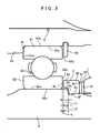
FIG. 3] FIG. 3 is an enlarged cross section view for showing a part of a ball bearing and a shimwasher. - An embodiment of the present invention will be described below according to
FIGs. 1 to 3 . An automatic transmission shown inFIG. 1 according to the present invention is preferably used for a vehicle of the FR type. InFIG. 1 , the left side indicated by X1 is the front side for the vehicle, and, the right side indicated by X2 is the rear side. Therefore the left in the figure is referred as the "front side", and the right side is referred as the "rear side". - As shown in
FIG. 1 , an automatic transmission 1 according to the present invention is preferably used for a vehicle of the FR type. Roughly from the front side to the rear side, the automatic transmission 1 includes a torque converter 10 having a lock-up clutch 20, and aspeed change mechanism 3 in an integrated case (simply referred to as a "case", hereinafter) 2 having ahousing case unit 2A, atransmission case unit 2B, and an end case C. The torque converter 10 is included in thehousing case unit 2A (and an engine case), thespeed change mechanism 3 is included in thetransmission case unit 2B, apartition wall member 2b fixed in a portion on the front side of thetransmission case unit 2B, and apartition wall member 2c at the rear side. - The torque converter 10 is housed in the
housing case unit 2A, and is arranged on theinput shaft 4 of thespeed change mechanism 3, which is described in detail below, and is interposed between aninput shaft 11 as the automatic transmission 1 connected to an output shaft (a crankshaft) of the engine, not shown, and theinput shaft 4 of thespeed change mechanism 3 as a transmission path. In addition, the torque converter 10 has afront cover 12 and arear cover 13 that are integrally coupled by welding or the like. Thefront cover 12 is connected to the output shaft of the engine via theinput shaft 11. As for therear cover 13, its outside diameter unit forms an outer contour of apump impeller 13a and the inner diameter end is connected to adrive gear 27 stored in apump body 26 of anoil pump 25 arranged on the inner periphery of thepartition wall member 2b. - On the front side of the
pump impeller 13a, a turbine runner 14a stored in aturbine cover 14 is arranged to face thepump impeller 13a, and astator 15 is arranged between thepump impeller 13a and the turbine runner 14a. Thestator 15 is arranged in the form of interposing a one-way clutch 16 on thesleeve 17 fixed by thepartition wall member 2b. While thepump impeller 13a has a higher level of rotation than that of the turbine runner 14a, the one-way clutch 16 restricts the rotation of thestator 15 so as to get a torque increase effect by changing the flow of hydraulic oil. When the rotation of thepump impeller 13a and the rotation of the turbine runner 14a become substantially the same, thestator 15 rotates freely by receiving the flow of hydraulic oil, and prevents the turbine runner 14a from giving a reverse torque by the flow of the hydraulic oil. Theturbine cover 14 is connected with aboss member 14b on the inner periphery. Theboss member 14b is spline-engaged and also rotatably connected with theinput shaft 4. - On the other hand, the lock-up clutch 20 is arranged on the front side of the turbine runner 14a in the
front cover 9. The lock-up clutch 20 includes apiston member 19 having afriction plate 19a, and adamper device 18 spline-engaged with thepiston member 19, and connected to theturbine cover 14. Thepiston member 19 is rotatably and axially freely slidably arranged on theinput shaft 4 via the boss member 14a in the inner periphery, and forms anoil chamber 21 in a sealed space between the boss member 14a and thefront cover 12. In addition, a top end in the outer periphery of thepiston member 19 is formed into a comb-tooth shape, also formed on the outer periphery of adrive plate 18b of thedamper device 18, and engaged with a spline. - The
damper device 18 includes the disk-shapeddrive plate 18b, two integrally connected drivenplates drive plate 18b, andcoil springs coil spring drive plate 18b and in a swollen part formed in the drivenplate drive plate 18b and the drivenplates - Between the
damper device 18 and thepiston member 19, anoil chamber 22 is formed and acted by an internal pressure in the torque converter 10, and it is structured to be able to axially press, drive and control thepiston member 19 by controlling oil pressure of theoil chamber 21 and that of theoil chamber 22 via an oil passage, not shown. In short, when thepiston member 19 is pressed and driven to the front side, based on a pressure difference between theoil chambers friction plate 19a engages with thefront cover 12, and thepiston member 19 and thefront cover 12 rotate integrally, causing a lock-up state where the rotation of thefront cover 12 is directly transmitted to theinput shaft 4 via thedamper device 18. In addition, thepiston member 19, when pressed and driven to the rear side, causes a fluid transmission state where the rotation of thefront cover 12 is transmitted to theinput shaft 4 via thepump impeller 13a and the turbine runner 14a. - The
speed change mechanism 3 is explained. Thespeed change mechanism 3 includes theinput shaft 4 rotatably supported by thepartition wall member 2b, theintermediate shaft 5 fitted with the rear end of theinput shaft 4, and anoutput shaft 6 rotatably fitted to the rear end of theintermediate shaft 5, and rotatably supported by asleeve unit 2d of thepartition wall member 2c of thecase 2 that is described in detail below, and structures a single-shaft alignedcenter axis 3A by theinput shaft 4, theintermediate shaft 5, theoutput shaft 6. It should be noted that theintermediate shaft 5 in the automatic transmission 1 is structured to be spline-engaged with, and to be rotated in synchronization with the input shaft 4 (not illustrated) although separated from theinput shaft 4. Therefore, theintermediate shaft 5 is a part of an input shaft in a broad sense. - In addition, on the
center axis 3A, agear mechanism 3B including planetary gears, a plurality of rotary members (for example, 31, 32) connecting the gears, and a clutch or a brake (for example, a break B-2) is arranged. Thegear mechanism 3B is structured so as to shift speeds by changing a transmission path for transmission from theinput shaft 4 to theoutput shaft 6 based on the engagement condition of the clutch or brake. - The gears and the plurality of rotary members are, in the diameter direction, rotatably supported by a bush or a needle bearing (for example, 51, 52, and 53) for the
center axis 3A (theinput shaft 4, theintermediate shaft 5, and the output shaft 6), and are also supported by thepartition wall member 2b and thepartition unit 2c for the axial direction (indicated by X1-X2) by the thrust bearing (for example, 42) interposed between the respective members. - A supporting structure of the
output shaft 6 as a main part of the present invention is explained withFIGs. 2 and3 . As shown inFIG. 2 , in thecase 2, apartition unit 2c formed in substantially disk shape and partitioning thespeed change mechanism 3 is arranged on a boundary part with thetransmission case unit 2B and theend case unit 2C, and thesleeve unit 2d coating the outer periphery of theoutput shaft 6 is formed in the inner periphery of thepartition unit 2c. In aninner periphery 2e of thesleeve unit 2d, a (first)step portion 2f whose rear side has larger diameter than its front side, in short, that abuts the X1 direction side (the axially input shaft side) is formed, more specifically, anouter race 61 of aball bearing 60 described in detail below, is assembled and prevented from slipping off by asnap ring 65. - On the other hand, the
output shaft 6 is arranged in the shape of penetrating via thesleeve unit 2d, and has a flange unit 6a that is formed in a flange shape in the front side end, and connected to the one of the planetary gears, not shown, via ahub member 31. In addition, acylindrical face 62c fitting aninner race 62 of theball bearing 60 is formed in anouter periphery 6e of theoutput shaft 6, and a (second)step portion 6c whose rear side has larger diameter than its front side, in short, that abuts the X1 direction side (the axially input shaft side) is formed, and is structured to be fitted and contacted with shimwasher 8 (described later). Furthermore, in the outer periphery more backward than thestep portion 6c, aspline 6s is formed and a flange yoke 7 (described later) is structured to be able to be spline-engaged with aspline 7s. Then amale screw unit 6g, in the further backward side of thespline 6s, is formed to be able to threadably engage with anut 9 fastening theflange yoke 7 for the front side. - The front part of the
output shaft 6 is formed to be hollow and rotatably fitted to the outer periphery of theintermediate shaft 5 via theneedle bearing 52, and to have aninner periphery 6f fitted to an rearend circumference side 5b of thehollow shaft 5. Specifically, theintermediate shaft 5 and theoutput shaft 6 are fitted in the diameter direction and are loosely fitted for the axial direction (having looseness), allowing theintermediate shaft 5 to move slightly for the axial direction so as to able to allow expansion or contraction due to, for example, a temperature change and torsion at the time of the torque transmission. - In addition, in the
intermediate shaft 5, the flange unit 5a in the flange form connected to the one of the planetary gears, not shown, via thedrum member 32 is formed, and thethrust bearing 42 is interposed between the flange unit 5a and the flange unit 6a of theoutput shaft 6. Furthermore, theneedle bearing 51 and thebush 53 are interposed between theouter periphery 6e of theoutput shaft 6 and theinner periphery 2e of thesleeve unit 2d, and freely rotated, and athrust bearing 41 is interposed between aside face 6b at the rear side of the flange unit 6a of theoutput shaft 6 and aside face 2g at the front side of thesleeve unit 2d. - The
ball bearing 60 has aball 63, theouter race 61 and theinner race 62 that rotatably pinch the ball, and is fitted between theinner periphery 2e of thesleeve unit 2d and theouter periphery 6e of theoutput shaft 6. - Specifically, as shown in
FIG.3 , theouter race 61 is arranged so that its side face 61 a of the front side contacts thestep portion 2f of thesleeve unit 2d, and itsside face 61b of the rear side fits on a fitting surface 2ea of theinner periphery 2e of thesleeve unit 2d, and further itsside face 61b is abutted and prevented from slipping off by thesnap ring 65. In addition, the inner peripheral surface 52c of theinner race 62 is fitted on a fitting surface 6ea of theouter periphery 6e of theoutput shaft 6. - The shimwasher (the propeller shaft connecting member) 8 is structured such that a main body (contact portion) 8b and an
extension portion 8a extended to the front side relative to themain body 8b. An innerperipheral surface 8f of themain body 8b is fitted to and supported by aspigot supporting portion 6d in theouter periphery 6e of theoutput shaft 6, and aside face 8d of the front side is assembled to contact thestep portion 6c. In addition, theextension portion 8a is extended toward theinner race 62 in the outer periphery of thestep portion 6c and is structured so that its leadingend 8c has an empty space d that is described later with aside face 62a of the rear side of theinner race 62. - The flange yoke (the propeller shaft connecting member) 7 is arranged via
washers main body 8b of theshimwasher 8 and aside face 8e. Theflange yoke 7, as shown inFIG.2 , has theflange unit 7a and thesleeve unit 7b, and is fastened to a propeller shaft, not shown, by abolt 71 penetrating via abolt hole 7c bored in theflange unit 7a. Thesleeve unit 7b is spline-engaged with theoutput shaft 6 as stated above and, itsside face 7d of the front side is abutted via thewashers side face 8e of theshimwasher 8, and aside face 7e of the rear side is pressed by aside face 9a of thenut 9 by screwing thenut 9. In other words, theflange yoke 7 is pinched by thenut 9 for thestep portion 6c via theshimwasher 8, and thewashers output shaft 6. - In addition, a space between the outer periphery of the
flange yoke 7 and thesleeve unit 2d is sealed by a seal ring S 1 and a space between the inner periphery of theflange yoke 7 and the outer periphery of theoutput shaft 6 is sealed by a seal ring S2, so that an automatic transmission fluid (ATF) enclosed in thecase 2 is sealed. - Support of thrust force (force in the axial direction) received by the
output shaft 6 is explained. For example, when thrust force toward the rear side (indicated by X2) occurs on theintermediate shaft 5 by thrust force and the like in the planetary gear, not shown, of thegear mechanism 3B, the flange unit 5a of theintermediate shaft 5 is supported by thesleeve unit 2d of thecase 2 via thethrust bearing 42, the flange unit 6a of theoutput shaft 6, and thethrust bearing 41. Accordingly, for example, even when theintermediate shaft 5 moves only by theclearance 42 of the thrust bearing 42 to the rear side, theoutput shaft 6 is positioned and supported on thecase 2 without moving to the rear side. - In addition, when, for example, the
flange yoke 7 is pulled by the propeller shaft, not shown, theoutput shaft 6 is also pulled to the rear side (indicated by X2) via thenut 9. Similarly, theoutput shaft 6 is positioned and supported on thesleeve unit 2d of thecase 2 via the flange region 6a and thethrust bearing 41 without moving to the rear side. - On the other hand, when the
flange yoke 7 is pressed by the propeller shaft, for example, first, thewashers shimwasher 8 are pressed to the front side (indicated by X1), and then theside face 8d of themain body 8b of theshimwasher 8 presses theoutput shaft 6 to the front side via thestep portion 6c. When theoutput shaft 6 moves to the front side at this time, the innerperipheral surface 62c of aninner race 62 of theball bearing 60 and a fitting surface 6ea of theoutput shaft 6 slide, theoutput shaft 6 slightly moves forward. Then aside face 8c of theextension portion 8a of theshimwasher 8 abuts in theside face 62a of theinner race 62, and receives pressing force from the propeller shaft by theinner race 62. Because theside face 61a of theouter race 61 of theball bearing 60, is supported by abutting thestep portion 2f, pressing force received by theinner race 62 from the propeller shaft is supported by thesleeve unit 2d. In other words, theoutput shaft 6, after moving only by the empty space d, is positioned and supported via theball bearing 60. - By the way, in the
speed change mechanism 3, the thrust bearings (including the thrust bearing 42) are arranged among respective rotary members including thehub member 31 and thedrum member 32 in the axial direction, and has a gap for the total clearance of the thrust bearings (including the clearance c42 of the thrust bearing 42). The gap for the axial direction in thespeed change mechanism 3, for example, in the automatic transmission, is about 0.48 - 1.2 mm with the addition of the product size deviations. Therefore, when the empty space d between theinner race 62 of theball bearing 60 and theextension portion 8a of theshimwasher 8, is set to, for example, about 0.05 - 0.2 mm, even if theoutput shaft 6 moves by that amount, the movement does not give any effect on the torque converter 10 and, in particular, the lock-upclutch 20. - Therefore, across the automatic transmission, first, the
output shaft 6 is installed to thesleeve unit 2d of thecase 2 with thethrust bearing 41, theneedle bearing 51, thebush 53 and the like interposed in between, and theball bearing 60 is assembled and prevented from falling off by thesnap ring 65 from the rear side. Afterwards, as shown inFIG. 3 , distance L1 between theside face 62a of theinner race 62 and thestep portion 6c is measured. In this way, measurement in an assembled state makes it possible to measure the correct distance L1 including the production size deviations in theball bearing 60, thesleeve unit 2d (in particular, thestep portion 2f), the output shaft 6 (in particular, thestep portion 6c) and the like. - On the other hand, a plurality of
shimwashers 8 whoseextension portions 8a are different in length are prepared. Then, ashimwasher 8 is selected that has the length L1 obtained by subtracting the empty space d from the distance L1 measured above, as the length of theextension portion 8a, and the selectedshimwasher 8 is assembled for thestep portion 6c of theoutput shaft 6 and thespigot supporting part 6d. With thewashers flange yoke 7 is spline-engaged with theoutput shaft 6 and fastened by thenut 9, so that theshimwasher 8 and theflange yoke 7 are fixed on theoutput shaft 6. When, for example, theextension portion 8a and themain body 8b of theshimwasher 8 are formed separately at this time, there is a possibility that theextension portion 8a is erroneously assembled between thestep portion 6c and themain body 8b. Erroneous assembly does not occur, however, because theextension portion 8a and themain body 8b are integrally formed. - In addition, for example, in the case of an automatic transmission in which the case is separately formed as a transmission case and an extension case, after providing a part for arranging a thrust bearing between a partition wall member of the transmission case and an output shaft, measuring an arranged position of the thrust bearing including product size deviations and accurately assembling the thrust bearing by selecting a washer and the like, it is possible to assemble the extension case where the ball bearing is disposed. However, in the case of the automatic transmission 1 in which the
case 2 is an integral one, measurement can be performed from the outside of thecase 2 after assembling theball bearing 60, andshimwasher 8 can be assembled without detaching theball bearing 60. This is more effective to prevent an increase in production process. - As described, according to the present invention, the
thrust bearing 41 is interposed between the flange unit 6a of theoutput shaft 6 and theside face 2g at the axially input shaft side (indicated by X1) of thesleeve unit 2d of thecase 2, and theball bearing 60 is interposed between theinner periphery 2e of thesleeve unit 2d and theouter periphery 6e of theoutput shaft 6 so that theside face 61a of theouter race 61 contacts thestep portion 2f. Further, theflange yoke 7 connectable to the propeller shaft is spline-engaged with the outer periphery of theoutput shaft 6, and, upon being pressed in the axially input shaft side by the propeller shaft, theflange yoke 7 contacts theside face 62a of theinner race 62 of theball bearing 60 via theshimwasher 8. Thus, when tensile force occurs on theoutput shaft 6 from the propeller shaft via theflange yoke 7 or when thrust force of thegear mechanism 3B is given, thethrust bearing 62 can receive such force. Further, when pressing force occurs from the propeller shaft via theflange yoke 7 and theshimwasher 8, theball bearing 60 can receive the force. In other words, the force generated on theball bearing 60 is changed to only the force to be applied to the axially input shaft side. This makes it possible to improve durability and compactness of theball bearing 60, while preventing the lock-up clutch 20 from being affected by the expansion and contraction of the propeller shaft. - In addition, after the
ball bearing 60 is assembled, it is possible to measure from the outside ofcase 2 accurate size (that is, distance L1) including the product size deviations for theball bearing 60, and to use the shape of theshimwasher 8 according to the size. This facilitates the measurement, while preventing an increase in production process. - In addition, the
flange yoke 7 and theshimwasher 8 are fastened at the axially input shaft side via themain body 8b of theshimwasher 8 for thestep portion 6c by thenut 9, and when theextension portion 8a is pressed axially toward the input shaft by the propeller shaft, it connects theside face 62a of theinner race 62 of theball bearing 60. Thus, theflange yoke 7 can be fixed on theoutput shaft 6, and theball bearing 60 can receive the force upon being pressed by the propeller shaft. - Furthermore, the
extension portion 8a of theshimwasher 8, when not pressed axially toward the input shaft by the propeller shaft, shares with theside face 62a of theinner race 62 of theball bearing 60 the empty space d which is smaller than a clearance in the axial direction possessed in thespeed change mechanism 3. This prevents, when not pressed by the propeller shaft, the ball bearing 60 from a single-side contact. Further, upon being pressed by the propeller shaft, theoutput shaft 6 moves to the extent of the empty space d so that the pressing force is received by theball bearing 60, while the movement of theoutput shaft 6 is absorbed in thespeed change mechanism 3. This prevents the lock-up clutch 20 from being affected by the pressure applied by the propeller shaft. - Further, the clearance in the axial direction which the
speed change mechanism 3 has can be determined by the sum total of clearances between the rotary members in thegear mechanism 3B and the thrust bearings. - Further, the
extension portion 8a of theshimwasher 8 is provided with a length so as to form the empty space d according to the distance between theside face 62a of theinner race 62 of theball bearing 60 and thestep portion 6c. Thus, only by precisely adjusting the length L2 of theextension portion 8a from theside face 6c of themain body 8b of theshimwasher 8 to the measured distance L1 between theside face 62a of theinner race 62 and thestep portion 6c, the empty space d can be formed, eliminating the need to form theflange yoke 7 with high accuracy. When theextension portion 8a and themain body 8b are formed separately, for example, there is a possibility for theextension portion 8a to be assembled erroneously between thestep portion 6c and themain body 8b. However, such an erroneous assembly can be prevented because themain body 8b and theextension portion 8a of theshimwasher 8 are integrally formed. - Furthermore, from among a plurality of shimwashers having the
extension portion 8a of a different length, theshimwasher 8 is selected and applied that has the length L2 equal to the length of theextension 8a to form the empty space d. This eliminates the need to process theshimwasher 8 for each product individually, enabling to form the empty space d with high accuracy. - In particular, the
case 2 is integrally formed with thetransmission case unit 2B including thespeed change mechanism 3 and thesleeve unit 2d. For example, measurement including the product size deviations inside thecase 2 for theball bearing 60 is not easy and also assembling parts (a washer and the like) with high accuracy according to the measurement causes an increase in production process. In the automatic transmission 1, however, measurement including the product size deviations outside of thecase 2 for theball bearing 60 can easily be performed, and an increase in production process such as detaching and reassembling theball bearing 60 can be prevented. - In the present embodiment according to the present invention, as the propeller shaft connecting members, the
shimwasher 8 and theflange yoke 7 are separately formed, so that only theshimwasher 8 can be selectively used. However, the present invention is not limited to this. Even integrally forming theshimwasher 8 and theflange yoke 7, and selecting the integral part having the length L2 corresponding to theextension portion 8a, or processing the integral part so as to have the length L2 fall within the scope of technical idea of the present invention that a measurement of the distance L1 is facilitated and a process to detach theball bearing 60 is removed. - Further, although the embodiment describes a multi-stage automatic transmission, the automatic transmission according to the present invention is not limited to this, and the present invention may be applied to a continuously variable automatic transmission such as a belt type or a toroidal type.
- An automatic transmission according to the present invention can be used for an automatic transmission mounted to a car, a truck, a bus, a farm machine, and the like, in particular, preferably used for those which have an output shaft connected to a propeller shaft, and a torque converter with a lock-up clutch, and which require improvement in more compactness and higher durability.
Claims (7)
- An automatic transmission comprising:a case;a speed change mechanism including an input shaft and an output shaft, the two shafts being rotatably supported for the case and forming a single-shaft aligned center axis, and a gear mechanism on the center axis; anda torque converter having a lock-up clutch arranged axially freely slidably toward and away from the input shaft, whereinthe case including a sleeve unit coating the outer periphery of the output shaft,the output shaft including a flange unit arranged opposite a side face of the sleeve unit on the axially input shaft side,the sleeve unit having a first step portion in an inner periphery thereof,the automatic transmission further comprising:a thrust bearing interposed between the flange unit and the side face of the sleeve unit on the axially input shaft side;a ball bearing including an outer race, a side face of which contacting the first step portion toward the axially input shaft side, and interposed between the inner periphery of the sleeve unit and the outer periphery of the output shaft; anda propeller shaft connecting member capable of connecting with a propeller shaft, spline-engaging with the outer periphery of the output shaft, and contacting a side face of an inner race of the ball bearing upon being pressed axially toward the input shaft side by the propeller shaft.
- The automatic transmission according to claim 1, wherein:the output shaft has a second step portion provided opposite the axially input shaft side relative to the ball bearing on the outer periphery, and abutting toward the axially input shaft side;the propeller shaft connecting member has a contact portion contacting the second step portion, and an extension portion extending toward an outer periphery of the second step portion;the output shaft further includes a fastening member fastening the propeller shaft connecting member, toward the axially input shaft side, to the second step portion via the contact portion; andthe extension portion contacts the side face of the inner race of the ball bearing upon being pressed axially toward the input shaft side by the propeller shaft.
- The automatic transmission according to claim 2, wherein the extension portion, when not pressed axially toward the input shaft side by the propeller shaft, shares with the side face of the inner race of the ball bearing, an empty space which is smaller than a clearance in the axial direction possessed in the speed change mechanism.
- The automatic transmission according to claim 3, wherein:in the speed change mechanism, the input shaft and the output shaft are loosely fitted in the axial direction, and a plurality of rotary members in the gear mechanism are rotatably supported by a plurality of thrust bearings in the axial direction, andthe clearance in the axial direction possessed in the speed change mechanism is the sum total of clearances between the rotary members in the gear mechanism and the thrust bearings.
- The automatic transmission according to claim 3 or 4, wherein:the propeller shaft connecting member includes a shimwasher integrally formed with the contact portion and the extension portion, and a flange yoke having a flange unit connected with the propeller shaft and a boss unit which is spline-engaged with the output shaft, andthe extension portion of the shimwasher is provided with a length so as to form the empty space according to a distance between the side face of the inner race of the ball bearing and the second step portion.
- The automatic transmission according to claim 5, wherein, from among a plurality of shimwashers having the extension portion of a different length, the shimwasher is selected and applied that has a length equal to the length of the extension portion.
- The automatic transmission according to any one of claims 3 to 6, wherein the case is integrally formed with a transmission case unit encasing the speed change mechanism, and the sleeve unit.
Applications Claiming Priority (2)
| Application Number | Priority Date | Filing Date | Title |
|---|---|---|---|
| JP2005344760A JP4652217B2 (en) | 2005-11-29 | 2005-11-29 | Automatic transmission |
| PCT/JP2006/322249 WO2007063684A1 (en) | 2005-11-29 | 2006-11-08 | Automatic transmission |
Publications (3)
| Publication Number | Publication Date |
|---|---|
| EP1956271A1 true EP1956271A1 (en) | 2008-08-13 |
| EP1956271A4 EP1956271A4 (en) | 2011-04-20 |
| EP1956271B1 EP1956271B1 (en) | 2012-10-03 |
Family
ID=38092020
Family Applications (1)
| Application Number | Title | Priority Date | Filing Date |
|---|---|---|---|
| EP06823153A Ceased EP1956271B1 (en) | 2005-11-29 | 2006-11-08 | Automatic transmission |
Country Status (5)
| Country | Link |
|---|---|
| US (1) | US8066608B2 (en) |
| EP (1) | EP1956271B1 (en) |
| JP (1) | JP4652217B2 (en) |
| CN (1) | CN101292099B (en) |
| WO (1) | WO2007063684A1 (en) |
Cited By (1)
| Publication number | Priority date | Publication date | Assignee | Title |
|---|---|---|---|---|
| EP3038906A4 (en) * | 2013-08-28 | 2017-04-26 | Sikorsky Aircraft Corporation | Light weight propulsor gearbox |
Families Citing this family (5)
| Publication number | Priority date | Publication date | Assignee | Title |
|---|---|---|---|---|
| KR100986059B1 (en) * | 2007-08-22 | 2010-10-07 | 기아자동차주식회사 | Supports and Sleeves |
| DE102007058852A1 (en) * | 2007-12-06 | 2009-06-25 | Schaeffler Kg | Multiple clutch device |
| US8177648B2 (en) * | 2010-07-19 | 2012-05-15 | Ford Global Technologies, Llc | Lubricant circuit including a cap plug |
| US9074677B2 (en) * | 2011-03-14 | 2015-07-07 | Arvinmeritor Technology, Llc | Carrier assembly with threaded adjustment member |
| US9255603B2 (en) * | 2013-02-10 | 2016-02-09 | United Technologies Corporation | Test equipment with housing damping system |
Family Cites Families (17)
| Publication number | Priority date | Publication date | Assignee | Title |
|---|---|---|---|---|
| JPH0650141B2 (en) | 1984-08-17 | 1994-06-29 | アイシン・エィ・ダブリュ株式会社 | Transmission shaft support device for automatic transmission for four-wheel drive |
| JPS6383461A (en) * | 1986-09-26 | 1988-04-14 | Toyota Motor Corp | Shaft connection structure |
| CA1290581C (en) | 1986-09-26 | 1991-10-15 | Masaki Inui | Coupling structure for a rotating member and a shaft |
| JP2825522B2 (en) | 1989-04-19 | 1998-11-18 | アイシン・エィ・ダブリュ株式会社 | Automatic transmission |
| JP2777820B2 (en) * | 1989-05-10 | 1998-07-23 | アイシン・エィ・ダブリユ株式会社 | Automatic transmission lubrication system |
| JP3460162B2 (en) * | 1995-03-23 | 2003-10-27 | 日産ディーゼル工業株式会社 | Transmission shaft support structure |
| JP2001027310A (en) | 1999-07-16 | 2001-01-30 | Aisin Aw Co Ltd | Automatic transmission |
| JP3732056B2 (en) | 1999-10-19 | 2006-01-05 | ジヤトコ株式会社 | Output shaft support structure |
| JP2003254412A (en) | 2002-03-06 | 2003-09-10 | Aisin Seiki Co Ltd | Output shaft support mechanism for automatic transmission |
| DE10230861A1 (en) | 2002-07-09 | 2004-01-22 | Zf Friedrichshafen Ag | Shift gear, especially an automatic shift gear, for a motor vehicle has a planet design with a ring gear as the driven element, and a device for damping structure-borne noise flowing from the ring gear to a driven shaft |
| JP4259079B2 (en) | 2002-09-25 | 2009-04-30 | アイシン精機株式会社 | Output shaft support structure for automatic transmission |
| JP2005113974A (en) * | 2003-10-03 | 2005-04-28 | Aisin Aw Co Ltd | Vehicular automatic transmission |
| EP1718887B1 (en) * | 2004-02-24 | 2011-08-24 | The Timken Company | Thermally compensated differential |
| US7384366B2 (en) * | 2004-03-12 | 2008-06-10 | Borgwarner Inc. | Transfer case with torque synchronizer clutching |
| US7175560B2 (en) * | 2005-01-20 | 2007-02-13 | American Axle & Manufacturing, Inc. | Thermally compensating bearing preload arrangement in axle assembly |
| US7543520B2 (en) * | 2006-01-27 | 2009-06-09 | Gm Global Technology Operations, Inc. | Extension housing to transmission case attachment |
| JP5006691B2 (en) * | 2007-04-27 | 2012-08-22 | 住友重機械工業株式会社 | Hypoid gear motor and manufacturing method thereof |
-
2005
- 2005-11-29 JP JP2005344760A patent/JP4652217B2/en not_active Expired - Fee Related
-
2006
- 2006-11-08 WO PCT/JP2006/322249 patent/WO2007063684A1/en not_active Ceased
- 2006-11-08 CN CN200680038927.8A patent/CN101292099B/en not_active Expired - Fee Related
- 2006-11-08 US US12/083,717 patent/US8066608B2/en not_active Expired - Fee Related
- 2006-11-08 EP EP06823153A patent/EP1956271B1/en not_active Ceased
Cited By (1)
| Publication number | Priority date | Publication date | Assignee | Title |
|---|---|---|---|---|
| EP3038906A4 (en) * | 2013-08-28 | 2017-04-26 | Sikorsky Aircraft Corporation | Light weight propulsor gearbox |
Also Published As
| Publication number | Publication date |
|---|---|
| JP2007147022A (en) | 2007-06-14 |
| US20090139370A1 (en) | 2009-06-04 |
| CN101292099A (en) | 2008-10-22 |
| JP4652217B2 (en) | 2011-03-16 |
| WO2007063684A1 (en) | 2007-06-07 |
| CN101292099B (en) | 2011-03-30 |
| EP1956271B1 (en) | 2012-10-03 |
| EP1956271A4 (en) | 2011-04-20 |
| US8066608B2 (en) | 2011-11-29 |
Similar Documents
| Publication | Publication Date | Title |
|---|---|---|
| EP1156235B1 (en) | Continuously variable belt transmission | |
| US7585243B2 (en) | Automatic transmission | |
| KR20050005496A (en) | Gearshift Transmission for a Motor Vehicle Having a Hydraulically Actuatable Multi-Disc Clutch | |
| JP4318822B2 (en) | Lubricating oil supply device for continuously variable transmission | |
| US6824494B2 (en) | Planetary gear unit | |
| EP2003031A9 (en) | Parking lock device for transmission | |
| EP1956271B1 (en) | Automatic transmission | |
| US5928104A (en) | Supporting structure for one-way clutch | |
| US10907702B2 (en) | Transmission device | |
| JP5037562B2 (en) | Torque converter stator shaft flange structure | |
| US7690491B2 (en) | Twin-clutch device | |
| JP4583139B2 (en) | Assembling structure and assembling method of continuously variable transmission | |
| EP1832782B1 (en) | Planetary gear device | |
| US6679132B2 (en) | Transmission | |
| US7089732B2 (en) | Transmitting system for small-sized vehicle | |
| JP2007298139A (en) | Belt type continuously variable transmission | |
| JPH0796897B2 (en) | Counter gear support device for automatic transmission | |
| JP2017219111A (en) | Continuously variable transmission | |
| JPH1163123A (en) | Automatic transmission | |
| JPH10274319A (en) | Belt type transmission for vehicles | |
| US20200398654A1 (en) | Power transmission device | |
| JP2002106669A (en) | Continuously variable transmission | |
| JP2001182792A (en) | Continuously variable transmission for vehicles | |
| JPS62283023A (en) | Power transmission shaft connecting device in automatic gear | |
| JP2011117508A (en) | Fixing structure for member to be fixed |
Legal Events
| Date | Code | Title | Description |
|---|---|---|---|
| PUAI | Public reference made under article 153(3) epc to a published international application that has entered the european phase |
Free format text: ORIGINAL CODE: 0009012 |
|
| 17P | Request for examination filed |
Effective date: 20080402 |
|
| AK | Designated contracting states |
Kind code of ref document: A1 Designated state(s): DE GB |
|
| RBV | Designated contracting states (corrected) |
Designated state(s): DE GB |
|
| A4 | Supplementary search report drawn up and despatched |
Effective date: 20110317 |
|
| GRAP | Despatch of communication of intention to grant a patent |
Free format text: ORIGINAL CODE: EPIDOSNIGR1 |
|
| DAX | Request for extension of the european patent (deleted) | ||
| GRAS | Grant fee paid |
Free format text: ORIGINAL CODE: EPIDOSNIGR3 |
|
| GRAA | (expected) grant |
Free format text: ORIGINAL CODE: 0009210 |
|
| AK | Designated contracting states |
Kind code of ref document: B1 Designated state(s): DE GB |
|
| REG | Reference to a national code |
Ref country code: GB Ref legal event code: FG4D |
|
| REG | Reference to a national code |
Ref country code: DE Ref legal event code: R096 Ref document number: 602006032306 Country of ref document: DE Effective date: 20121129 |
|
| RAP2 | Party data changed (patent owner data changed or rights of a patent transferred) |
Owner name: TOYOTA JIDOSHA KABUSHIKI KAISHA Owner name: AISIN AW CO., LTD. |
|
| PLBE | No opposition filed within time limit |
Free format text: ORIGINAL CODE: 0009261 |
|
| STAA | Information on the status of an ep patent application or granted ep patent |
Free format text: STATUS: NO OPPOSITION FILED WITHIN TIME LIMIT |
|
| 26N | No opposition filed |
Effective date: 20130704 |
|
| REG | Reference to a national code |
Ref country code: DE Ref legal event code: R097 Ref document number: 602006032306 Country of ref document: DE Effective date: 20130704 |
|
| PGFP | Annual fee paid to national office [announced via postgrant information from national office to epo] |
Ref country code: GB Payment date: 20210930 Year of fee payment: 16 |
|
| PGFP | Annual fee paid to national office [announced via postgrant information from national office to epo] |
Ref country code: DE Payment date: 20210929 Year of fee payment: 16 |
|
| REG | Reference to a national code |
Ref country code: DE Ref legal event code: R119 Ref document number: 602006032306 Country of ref document: DE |
|
| GBPC | Gb: european patent ceased through non-payment of renewal fee |
Effective date: 20221108 |
|
| PG25 | Lapsed in a contracting state [announced via postgrant information from national office to epo] |
Ref country code: GB Free format text: LAPSE BECAUSE OF NON-PAYMENT OF DUE FEES Effective date: 20221108 Ref country code: DE Free format text: LAPSE BECAUSE OF NON-PAYMENT OF DUE FEES Effective date: 20230601 |