EP1956116B1 - Removal of thermal barrier coatings - Google Patents
Removal of thermal barrier coatings Download PDFInfo
- Publication number
- EP1956116B1 EP1956116B1 EP08008023.7A EP08008023A EP1956116B1 EP 1956116 B1 EP1956116 B1 EP 1956116B1 EP 08008023 A EP08008023 A EP 08008023A EP 1956116 B1 EP1956116 B1 EP 1956116B1
- Authority
- EP
- European Patent Office
- Prior art keywords
- thermal barrier
- substrate
- bath
- barrier coating
- bondcoat
- Prior art date
- Legal status (The legal status is an assumption and is not a legal conclusion. Google has not performed a legal analysis and makes no representation as to the accuracy of the status listed.)
- Expired - Lifetime
Links
- 239000012720 thermal barrier coating Substances 0.000 title claims description 77
- 239000000758 substrate Substances 0.000 claims description 58
- 238000000034 method Methods 0.000 claims description 33
- XLYOFNOQVPJJNP-UHFFFAOYSA-N water Substances O XLYOFNOQVPJJNP-UHFFFAOYSA-N 0.000 claims description 29
- 229910000601 superalloy Inorganic materials 0.000 claims description 25
- PXHVJJICTQNCMI-UHFFFAOYSA-N Nickel Chemical group [Ni] PXHVJJICTQNCMI-UHFFFAOYSA-N 0.000 claims description 22
- 238000000576 coating method Methods 0.000 claims description 21
- 229910000951 Aluminide Inorganic materials 0.000 claims description 20
- XLYOFNOQVPJJNP-UHFFFAOYSA-M hydroxide Chemical compound [OH-] XLYOFNOQVPJJNP-UHFFFAOYSA-M 0.000 claims description 20
- 239000011248 coating agent Substances 0.000 claims description 19
- 239000003513 alkali Substances 0.000 claims description 14
- 230000004888 barrier function Effects 0.000 claims description 11
- 230000000694 effects Effects 0.000 claims description 11
- 229910001853 inorganic hydroxide Inorganic materials 0.000 claims description 11
- 229910052759 nickel Inorganic materials 0.000 claims description 11
- 230000003647 oxidation Effects 0.000 claims description 11
- 238000007254 oxidation reaction Methods 0.000 claims description 11
- PNEYBMLMFCGWSK-UHFFFAOYSA-N aluminium oxide Inorganic materials [O-2].[O-2].[O-2].[Al+3].[Al+3] PNEYBMLMFCGWSK-UHFFFAOYSA-N 0.000 claims description 9
- 229910045601 alloy Inorganic materials 0.000 claims description 8
- 239000000956 alloy Substances 0.000 claims description 8
- 239000007788 liquid Substances 0.000 claims description 5
- 229910017052 cobalt Chemical group 0.000 claims description 4
- 239000010941 cobalt Chemical group 0.000 claims description 4
- GUTLYIVDDKVIGB-UHFFFAOYSA-N cobalt atom Chemical group [Co] GUTLYIVDDKVIGB-UHFFFAOYSA-N 0.000 claims description 4
- QDOXWKRWXJOMAK-UHFFFAOYSA-N dichromium trioxide Chemical compound O=[Cr]O[Cr]=O QDOXWKRWXJOMAK-UHFFFAOYSA-N 0.000 claims description 2
- 239000000470 constituent Substances 0.000 claims 1
- KWYUFKZDYYNOTN-UHFFFAOYSA-M Potassium hydroxide Chemical compound [OH-].[K+] KWYUFKZDYYNOTN-UHFFFAOYSA-M 0.000 description 72
- 239000003518 caustics Substances 0.000 description 23
- BASFCYQUMIYNBI-UHFFFAOYSA-N platinum Chemical compound [Pt] BASFCYQUMIYNBI-UHFFFAOYSA-N 0.000 description 18
- 239000000126 substance Substances 0.000 description 18
- 238000007654 immersion Methods 0.000 description 17
- 238000009792 diffusion process Methods 0.000 description 16
- 239000002585 base Substances 0.000 description 9
- 238000005229 chemical vapour deposition Methods 0.000 description 9
- 229910001011 CMSX-4 Inorganic materials 0.000 description 7
- 239000000919 ceramic Substances 0.000 description 7
- 229910052697 platinum Inorganic materials 0.000 description 7
- HEMHJVSKTPXQMS-UHFFFAOYSA-M Sodium hydroxide Chemical compound [OH-].[Na+] HEMHJVSKTPXQMS-UHFFFAOYSA-M 0.000 description 6
- 229910052700 potassium Inorganic materials 0.000 description 6
- 230000008569 process Effects 0.000 description 6
- ZLMJMSJWJFRBEC-UHFFFAOYSA-N Potassium Chemical compound [K] ZLMJMSJWJFRBEC-UHFFFAOYSA-N 0.000 description 5
- 239000011591 potassium Substances 0.000 description 5
- MCMNRKCIXSYSNV-UHFFFAOYSA-N Zirconium dioxide Chemical compound O=[Zr]=O MCMNRKCIXSYSNV-UHFFFAOYSA-N 0.000 description 4
- 229910001233 yttria-stabilized zirconia Inorganic materials 0.000 description 4
- 239000010953 base metal Substances 0.000 description 3
- 229910010293 ceramic material Inorganic materials 0.000 description 3
- 238000001816 cooling Methods 0.000 description 3
- 230000006872 improvement Effects 0.000 description 3
- 238000009419 refurbishment Methods 0.000 description 3
- 238000012360 testing method Methods 0.000 description 3
- XEEYBQQBJWHFJM-UHFFFAOYSA-N Iron Chemical compound [Fe] XEEYBQQBJWHFJM-UHFFFAOYSA-N 0.000 description 2
- CPLXHLVBOLITMK-UHFFFAOYSA-N Magnesium oxide Chemical compound [Mg]=O CPLXHLVBOLITMK-UHFFFAOYSA-N 0.000 description 2
- 229910052784 alkaline earth metal Inorganic materials 0.000 description 2
- 238000010420 art technique Methods 0.000 description 2
- 238000004140 cleaning Methods 0.000 description 2
- 238000005328 electron beam physical vapour deposition Methods 0.000 description 2
- 238000009713 electroplating Methods 0.000 description 2
- 238000009413 insulation Methods 0.000 description 2
- 239000000463 material Substances 0.000 description 2
- 229910052751 metal Inorganic materials 0.000 description 2
- 239000002184 metal Substances 0.000 description 2
- 150000002894 organic compounds Chemical class 0.000 description 2
- 230000001590 oxidative effect Effects 0.000 description 2
- 238000005240 physical vapour deposition Methods 0.000 description 2
- 239000007921 spray Substances 0.000 description 2
- 229910000943 NiAl Inorganic materials 0.000 description 1
- 229910019142 PO4 Inorganic materials 0.000 description 1
- NPXOKRUENSOPAO-UHFFFAOYSA-N Raney nickel Chemical compound [Al].[Ni] NPXOKRUENSOPAO-UHFFFAOYSA-N 0.000 description 1
- 241000968352 Scandia <hydrozoan> Species 0.000 description 1
- 238000002083 X-ray spectrum Methods 0.000 description 1
- 238000007792 addition Methods 0.000 description 1
- 239000000654 additive Substances 0.000 description 1
- 230000000996 additive effect Effects 0.000 description 1
- 150000001342 alkaline earth metals Chemical class 0.000 description 1
- 229910052782 aluminium Inorganic materials 0.000 description 1
- XAGFODPZIPBFFR-UHFFFAOYSA-N aluminium Chemical compound [Al] XAGFODPZIPBFFR-UHFFFAOYSA-N 0.000 description 1
- 238000005422 blasting Methods 0.000 description 1
- 238000009835 boiling Methods 0.000 description 1
- AXCZMVOFGPJBDE-UHFFFAOYSA-L calcium dihydroxide Chemical compound [OH-].[OH-].[Ca+2] AXCZMVOFGPJBDE-UHFFFAOYSA-L 0.000 description 1
- 239000000920 calcium hydroxide Substances 0.000 description 1
- 229910001861 calcium hydroxide Inorganic materials 0.000 description 1
- 238000005524 ceramic coating Methods 0.000 description 1
- CETPSERCERDGAM-UHFFFAOYSA-N ceric oxide Chemical compound O=[Ce]=O CETPSERCERDGAM-UHFFFAOYSA-N 0.000 description 1
- 229910000422 cerium(IV) oxide Inorganic materials 0.000 description 1
- 239000013078 crystal Substances 0.000 description 1
- 238000000151 deposition Methods 0.000 description 1
- 238000004090 dissolution Methods 0.000 description 1
- 238000001017 electron-beam sputter deposition Methods 0.000 description 1
- 238000000724 energy-dispersive X-ray spectrum Methods 0.000 description 1
- 238000005516 engineering process Methods 0.000 description 1
- 238000001704 evaporation Methods 0.000 description 1
- 230000008020 evaporation Effects 0.000 description 1
- 238000010285 flame spraying Methods 0.000 description 1
- 239000011888 foil Substances 0.000 description 1
- 239000012634 fragment Substances 0.000 description 1
- 239000011521 glass Substances 0.000 description 1
- 238000010438 heat treatment Methods 0.000 description 1
- 238000010348 incorporation Methods 0.000 description 1
- 229910052742 iron Inorganic materials 0.000 description 1
- VTHJTEIRLNZDEV-UHFFFAOYSA-L magnesium dihydroxide Chemical compound [OH-].[OH-].[Mg+2] VTHJTEIRLNZDEV-UHFFFAOYSA-L 0.000 description 1
- 239000000347 magnesium hydroxide Substances 0.000 description 1
- 229910001862 magnesium hydroxide Inorganic materials 0.000 description 1
- 239000000395 magnesium oxide Substances 0.000 description 1
- 238000004519 manufacturing process Methods 0.000 description 1
- 229910000000 metal hydroxide Inorganic materials 0.000 description 1
- 150000004692 metal hydroxides Chemical class 0.000 description 1
- 150000002739 metals Chemical class 0.000 description 1
- 239000000203 mixture Substances 0.000 description 1
- HJGMWXTVGKLUAQ-UHFFFAOYSA-N oxygen(2-);scandium(3+) Chemical compound [O-2].[O-2].[O-2].[Sc+3].[Sc+3] HJGMWXTVGKLUAQ-UHFFFAOYSA-N 0.000 description 1
- NBIIXXVUZAFLBC-UHFFFAOYSA-K phosphate Chemical compound [O-]P([O-])([O-])=O NBIIXXVUZAFLBC-UHFFFAOYSA-K 0.000 description 1
- 239000010452 phosphate Substances 0.000 description 1
- 238000007747 plating Methods 0.000 description 1
- 239000010970 precious metal Substances 0.000 description 1
- 239000011253 protective coating Substances 0.000 description 1
- 230000001681 protective effect Effects 0.000 description 1
- 229910001173 rene N5 Inorganic materials 0.000 description 1
- 230000008439 repair process Effects 0.000 description 1
- 238000005480 shot peening Methods 0.000 description 1
- 239000002002 slurry Substances 0.000 description 1
- 239000007787 solid Substances 0.000 description 1
- 238000004901 spalling Methods 0.000 description 1
- 229910002076 stabilized zirconia Inorganic materials 0.000 description 1
- 229910052727 yttrium Inorganic materials 0.000 description 1
- RUDFQVOCFDJEEF-UHFFFAOYSA-N yttrium(III) oxide Inorganic materials [O-2].[O-2].[O-2].[Y+3].[Y+3] RUDFQVOCFDJEEF-UHFFFAOYSA-N 0.000 description 1
Images



Classifications
-
- C—CHEMISTRY; METALLURGY
- C23—COATING METALLIC MATERIAL; COATING MATERIAL WITH METALLIC MATERIAL; CHEMICAL SURFACE TREATMENT; DIFFUSION TREATMENT OF METALLIC MATERIAL; COATING BY VACUUM EVAPORATION, BY SPUTTERING, BY ION IMPLANTATION OR BY CHEMICAL VAPOUR DEPOSITION, IN GENERAL; INHIBITING CORROSION OF METALLIC MATERIAL OR INCRUSTATION IN GENERAL
- C23C—COATING METALLIC MATERIAL; COATING MATERIAL WITH METALLIC MATERIAL; SURFACE TREATMENT OF METALLIC MATERIAL BY DIFFUSION INTO THE SURFACE, BY CHEMICAL CONVERSION OR SUBSTITUTION; COATING BY VACUUM EVAPORATION, BY SPUTTERING, BY ION IMPLANTATION OR BY CHEMICAL VAPOUR DEPOSITION, IN GENERAL
- C23C26/00—Coating not provided for in groups C23C2/00 - C23C24/00
-
- C—CHEMISTRY; METALLURGY
- C23—COATING METALLIC MATERIAL; COATING MATERIAL WITH METALLIC MATERIAL; CHEMICAL SURFACE TREATMENT; DIFFUSION TREATMENT OF METALLIC MATERIAL; COATING BY VACUUM EVAPORATION, BY SPUTTERING, BY ION IMPLANTATION OR BY CHEMICAL VAPOUR DEPOSITION, IN GENERAL; INHIBITING CORROSION OF METALLIC MATERIAL OR INCRUSTATION IN GENERAL
- C23C—COATING METALLIC MATERIAL; COATING MATERIAL WITH METALLIC MATERIAL; SURFACE TREATMENT OF METALLIC MATERIAL BY DIFFUSION INTO THE SURFACE, BY CHEMICAL CONVERSION OR SUBSTITUTION; COATING BY VACUUM EVAPORATION, BY SPUTTERING, BY ION IMPLANTATION OR BY CHEMICAL VAPOUR DEPOSITION, IN GENERAL
- C23C30/00—Coating with metallic material characterised only by the composition of the metallic material, i.e. not characterised by the coating process
-
- C—CHEMISTRY; METALLURGY
- C23—COATING METALLIC MATERIAL; COATING MATERIAL WITH METALLIC MATERIAL; CHEMICAL SURFACE TREATMENT; DIFFUSION TREATMENT OF METALLIC MATERIAL; COATING BY VACUUM EVAPORATION, BY SPUTTERING, BY ION IMPLANTATION OR BY CHEMICAL VAPOUR DEPOSITION, IN GENERAL; INHIBITING CORROSION OF METALLIC MATERIAL OR INCRUSTATION IN GENERAL
- C23G—CLEANING OR DE-GREASING OF METALLIC MATERIAL BY CHEMICAL METHODS OTHER THAN ELECTROLYSIS
- C23G1/00—Cleaning or pickling metallic material with solutions or molten salts
- C23G1/14—Cleaning or pickling metallic material with solutions or molten salts with alkaline solutions
- C23G1/20—Other heavy metals
-
- C—CHEMISTRY; METALLURGY
- C23—COATING METALLIC MATERIAL; COATING MATERIAL WITH METALLIC MATERIAL; CHEMICAL SURFACE TREATMENT; DIFFUSION TREATMENT OF METALLIC MATERIAL; COATING BY VACUUM EVAPORATION, BY SPUTTERING, BY ION IMPLANTATION OR BY CHEMICAL VAPOUR DEPOSITION, IN GENERAL; INHIBITING CORROSION OF METALLIC MATERIAL OR INCRUSTATION IN GENERAL
- C23G—CLEANING OR DE-GREASING OF METALLIC MATERIAL BY CHEMICAL METHODS OTHER THAN ELECTROLYSIS
- C23G1/00—Cleaning or pickling metallic material with solutions or molten salts
- C23G1/28—Cleaning or pickling metallic material with solutions or molten salts with molten salts
- C23G1/32—Heavy metals
-
- F—MECHANICAL ENGINEERING; LIGHTING; HEATING; WEAPONS; BLASTING
- F01—MACHINES OR ENGINES IN GENERAL; ENGINE PLANTS IN GENERAL; STEAM ENGINES
- F01D—NON-POSITIVE DISPLACEMENT MACHINES OR ENGINES, e.g. STEAM TURBINES
- F01D5/00—Blades; Blade-carrying members; Heating, heat-insulating, cooling or antivibration means on the blades or the members
- F01D5/12—Blades
- F01D5/28—Selecting particular materials; Particular measures relating thereto; Measures against erosion or corrosion
- F01D5/288—Protective coatings for blades
-
- Y—GENERAL TAGGING OF NEW TECHNOLOGICAL DEVELOPMENTS; GENERAL TAGGING OF CROSS-SECTIONAL TECHNOLOGIES SPANNING OVER SEVERAL SECTIONS OF THE IPC; TECHNICAL SUBJECTS COVERED BY FORMER USPC CROSS-REFERENCE ART COLLECTIONS [XRACs] AND DIGESTS
- Y02—TECHNOLOGIES OR APPLICATIONS FOR MITIGATION OR ADAPTATION AGAINST CLIMATE CHANGE
- Y02T—CLIMATE CHANGE MITIGATION TECHNOLOGIES RELATED TO TRANSPORTATION
- Y02T50/00—Aeronautics or air transport
- Y02T50/60—Efficient propulsion technologies, e.g. for aircraft
Definitions
- the present invention relates to removal of thermal barrier protective coatings and, more particularly, to rapid chemical removal of such thermal barrier coatings by ambient pressure, elevated temperature hydroxide medium.
- thermal barrier coatings comprising alumina or zirconia based ceramics have provided an insulative layer protecting the superalloy substrate.
- a superalloy substrate is first coated with a metallic bondcoat, such as a diffusion aluminide and/or MCrAlY overlay coating (where M is nickel and/or cobalt). This bondcoat is then coated with an insulative layer of alumina or stabilized zirconia.
- thermal barrier coating production and/or turbine engine component refurbishment removal of the ceramic insulating layer may be necessary.
- Thermal barrier coatings traditionally have been removed by grit blasting, HF cleaning, water jet, or caustic autoclave chemical removal at high pressures and temperatures. These operations are energy intensive, require long processing times, are labor intensive, damage underlying bondcoats, decrease component wall thickness, and increase surface film cooling hole sizes in multi-passage air-cooled component.
- US-A-5,679,270 discloses the removal of a thermal barrier coating from a superalloy substrate in the refurbishment of engine-run components which are then recoated with a fresh thermal barrier coating.
- the component is immersed in an aqueous caustic solution comprising e.g. KOH or NaOH in a concentration of at least 40 weight % of the solution while the solution is at ambient pressure and elevated temperature.
- US-A-5,643,474 discloses a method for removing a thermal barrier coating from a superalloy substrate having a bondcoat thereon without damaging or affecting the bondcoat or the superalloy substrate. After removal of the thermal barrier coating, the substrate with its bondcoat is recoated with a fresh thermal barrier coating. For removing the used thermal barrier coating, the article is treated in a autoclave with an organic caustic solution comprising an organic compound and water, and it is said that the organic compound must be present in a sufficient amount to cause all of the thermal barrier coating to be removed.
- the present invention provides a chemical method of removing a ceramic thermal barrier coating from substrates of a wide variety of configurations at ambient pressure and in very short times as compared to prior art techniques described above without damage to the substrate or any bondcoat thereon.
- the component having the thermal barrier coating is immersed in an inorganic hydroxide bath having a high concentration of alkali or alkaline earth hydroxide with the bath at ambient (atmospheric) pressure and elevated temperature for a time sufficient to effect detachment of the thermal barrier coating from a substrate by preferential attack of an intermediate oxide layer and removal from the substrate.
- the hydroxide bath can comprise an inorganic hydroxide liquid bath having at least about 50 weight %, preferably at least 80 weight %, of an alkali or alkaline earth hydroxide and the balance essentially water.
- the inorganic hydroxide bath can comprise 90 weight % KOH and 10 weight % water at 650 degrees F disposed in a vessel open to atmospheric pressure.
- the component having the thermal barrier coating thereon can be immersed in the hydroxide bath and then optionally immersed in a water bath to remove the thermal barrier coating without damage to the substrate or any bondcoat present thereon.
- the hot component is removed from the caustic bath after a selected time and immersed in a water bath whereby the water bath is heated by the hot component and agitated to facilitate removal of any remaining thermal barrier coating from the substrate.
- the present invention provides a thermal barrier recoated component that exhibits improved resistance to oxidation following removal of the used thermal barrier coating pursuant to the present invention and recoating with a fresh thermal barrier coating.
- the alkali or alkaline earth element of the caustic bath remains on and/or in the surface of the stripped component in a detectable amount and becomes incorporated into the bondcoat or substrate, if no bondcoat is present, when the fresh thermal barrier coating is applied to the stripped component in an amount effective to increase oxidation resistance of the recoated component.
- the present invention involves a chemical method of removing a ceramic thermal barrier coating from a superalloy and other substrates of a wide variety of configurations at ambient pressure and in very short times without damage to the substrate or any bondcoat thereon.
- the thermal barrier coating typically comprises an outer ceramic thermal insulating coating or layer 10 disposed on an intermediate oxide layer 12 comprising for example only, an alumina layer, chromia layer, and the like, Figure 3A .
- the intermediate oxide layer 12 is formed or deposited on an inner bondcoat layer 14 which may comprise a metallic layer, such as an MCrA1Y alloy overlay where M is nickel and/or cobalt, and/or a diffusion aluminide layer which may be modified by inclusion of Pt or other precious metal(s) and other elemental additions, such as reactive metals including Si, Hf, Y, and/or Zr and alkali and alkaline earth metals, such as K and Mg.
- a metallic layer such as an MCrA1Y alloy overlay where M is nickel and/or cobalt
- a diffusion aluminide layer which may be modified by inclusion of Pt or other precious metal(s) and other elemental additions, such as reactive metals including Si, Hf, Y, and/or Z
- the intermediate layer can be formed by oxidation of the bondcoat by heating in an oxidizing atmosphere to thermally grow the layer thereon as a thin oxide layer.
- the intermediate layer can be deposited by chemical vapor deposition on the bondcoat as a thin layer of ceramic material.
- the MCrA1Y layer can be deposited on the substrate S by plasma spray, flame spraying, electron-beam-physical vapor deposition, sputtering and other known techniques.
- the diffusion aluminide layer can be formed on the substrate by chemical vapor deposition (CVD), pack cementation, above-the-pack, slurry and other known deposition techniques.
- the bondcoat layer typically ranges in thickness from about 25.4 ⁇ m (1 mil) to about 254 ⁇ m (10 mils), such as about 127 to about 203.2 ⁇ m (5 to about 8 mils) for MCrA1Y and about 25.4 ⁇ m to about 76.2 ⁇ m (1 to about 3 mils) for diffusion aluminide, for purposes of illustration and not limitation. If the substrate comprises an alumina forming alloy, the bondcoat may be omitted, or alumina may be applied to the substrate as a layer sans bondcoat.
- the outer thermal insulating layer comprises a ceramic material such as zirconia, alumina, and others known for use as thermal barrier layers.
- the ceramic thermal barrier material may be modified to include other ceramic materials such as yttria, ceria, scandia, magnesia, and similar materials.
- the thermal insulating layer may be a graded layer that changes composition from the outer free surface thereof to the inner surface thereof proximate the next inner layer (e.g. intermediate layer or bondcoat) or the substrate.
- the thermal insulating layer typically is applied or deposited by air plasma spray or electron beam physical vapor deposition (EB PVD) at suitable elevated substrate coating temperatures.
- EB PVD electron beam physical vapor deposition
- the thermal insulating layer When applied by ED PVD, the thermal insulating layer exhibits a microstructure of columnar grains extending generally perpendicular to the bondcoat and substrate surface, Fig. 3A .
- the thermal insulating layer typically ranges in thickness from about 50.8 ⁇ m (2 mils) to about 508 ⁇ m (20 mils) for purposes of illustration only.
- the substrate S can comprise nickel, cobalt or iron base superalloys in cast or wrought form commonly used for gas turbine engine components, such as turbine blades and vanes, nozzle guide vanes.
- Examples of common superalloy and other substrates to which the invention is applicable include, but are not limited to, single crystal and directionally solidified superalloys such as CMSX-4, PWA-1484, Rene' N5, Rene'142, PWA-1480, and CM-186LC and other high temperature polycrystalline alloys such as Rene'80, GTD-111 and IN-738 for purposes of illustration only.
- the substrate can have a wide variety of configurations such as complex turbine blade and vane shapes, simple flat or curvilinear shapes, and other myriad shapes.
- Thermal barrier coatings as discussed or mentioned herein, are well known and described in such patents as U.S. Patent 4 405 659 ; 4 676 994 ; 5 015 502 ; 5 514 482 and 5 716 720 for example.
- an engine-run or other thermal barrier coated component such as a superalloy turbine blade, vane and other component
- a refurbishment or repair operation wherein the thermal barrier coating 10 is removed from the component (substrate) without significant chemical attack or other damage to the component substrate or any bondcoat 14 thereon by a chemical removal method at ambient pressure and in very short times as compared to prior art techniques described above without damage to the substrate or any bondcoat thereon.
- the component having the used thermal barrier coating 10 is immersed in an inorganic hydroxide liquid bath having a high concentration of alkali or alkaline earth hydroxide, such as KOH, NaOH, Ca(OH) 2 , Mg(OH) 2 with the bath at ambient (atmospheric) pressure and elevated temperature, such as for example only at about 135 °C (275 degrees F) and above, for a time sufficient to effect detachment of the thermal barrier coating 10 for removal from the substrate and bondcoat.
- alkali or alkaline earth hydroxide such as KOH, NaOH, Ca(OH) 2 , Mg(OH) 2
- An exemplary hydroxide liquid bath comprises an inorganic hydroxide solution or liquid having at least about 50 weight %, preferably at least 80 weight %, of an alkali or alkaline earth hydroxide and the balance essentially water.
- the inorganic hydroxide bath preferably can comprise 90 weight % KOH and 10 weight % water at 343 °C (650 degrees F) disposed in a vessel open to atmospheric pressure. Water is added to the bath as necessary during use to replenish water lost by evaporation.
- the component having the thermal barrier coating 10 thereon can be immersed in the bath for a short time (e.g.
- the hot component is removed from the hot caustic bath after a selected time and immersed in a water bath whereby the water bath is heated by the hot component and boiled/agitated to facilitate removal of any remaining, clinging thermal barrier coating from the substrate.
- the present invention was demonstrated using a beaker (capacity of one liter) disposed on a laboratory bench in air wrapped in a Kaowool thermal insulation inner blanket and an outer wrapping of aluminum foil.
- a thermocouple was inserted between the beaker and the thermal insulation to monitor temperature of the caustic bath.
- a watch glass was placed on the top of the beaker to permit viewing of the thermal barrier coating removal process.
- the beaker was filled with a metal hydroxide flake, particularly hydrated KOH flake (90% KOH-10% water by weight), and was heated by electrical resistance to produce a molten bath at 343 °C (650 degrees F).
- the thermal barrier coated samples described below were submerged in the molten KOH bath until the thermal barrier coating started to fragment and peel off the part by virtue of preferential chemical attack or dissolution of the alumina or other oxide layer 12 located between the bondcoat and thermal barrier coating, removing substantially all of the thermal barrier coating.
- the hot part was removed from the molten KOH bath and rinsed in a room temperature water bath by immersion therein. The hot component caused localized boiling of water in contact therewith and facilitated removal of remaining minor amount of thermal barrier coating which had not previously fallen off the part in the bath.
- FIGS. 3A and 3B are photomicrographs at 500X of CMSX-4 nickel base superalloy samples coated with a thermal barrier coating before immersion and after simmersion in the molten bath. Removal of the thermal barrier coating 10 without base metal attack or bondcoat attack is evident from these Figures.
- the chemical removal procedure also was conducted on a Rene'142 substrate alloy (a hollow turbine blade) sample coated with a CVD low activity diffusion aluminide designated MDC 210 having a total thickness of about 25.4 ⁇ m (0.001 inch).
- the low activity diffusion coating comprises an additive NiAl outer layer 22 and an inner refractory element rich diffusion zone 24 adjacent substrate S.
- the sample was submerged for approximately nine minutes in the above molten KOH bath (90% KOH-10% water by weight) in air and then rinsed in the water bath.
- Figures 4A and 4B are photomicrographs at 500X of the Rene'142 sample coated with the CVD low activity aluminide coating before immersion and after immersion in the molten KOH bath. These Figures indicate that there was no harmful attack of the simple aluminide diffusion coating by the treatment.
- the present invention also involves a thermal barrier recoated component that exhibits improved resistance to oxidation following removal of the used thermal barrier coating pursuant to the present invention and recoating with a fresh thermal barrier coating.
- the alkali or alkaline earth element of the caustic bath has been discovered to remain on the surface of the stripped component (either on the bondcoat or on the superalloy substrate if no bondcoat is present) in a detectable amount and to become incorporated in the bondcoat (or superalloy substrate) when the fresh thermal barrier coating is applied to the stripped component at elevated temperature in an amount effective to increase oxidation resistance of the bondcoat (or superalloy substrate) and thus the recoated component having the thermal barrier coating thereon.
- the bondcoat if present can comprise an aluminide, MrCrAlY, or other bondcoat.
- one set of samples included CF6-80C2 first stage turbine blades that were made of Rene' N5 superalloy and that are designed by the engine manufacturer to be air cooled in service by internal serpentine passages with numerous surface film cooling holes.
- the other set of samples included one inch diameter buttons comprised of Rene' N5 superalloy.
- the aforementioned button samples were Pt electroplated as described in U.S. Patent 3 677 789 using a phosphate electroplating bath and CVD aluminized as described in U.S. Patent 5 658 614 to form a platinum modified diffusion aluminide coating having a thickness of 63.5 ⁇ m (0.0025 inch). No TBC coating was applied to the aluminide coating.
- the coatings on the turbine blade samples already contained potassium from the potassium hydroxide Pt plating process, and so, were not suitable samples to show potassium pick-up by the above chemical removal procedure for removing the thermal barrier coating.
- One coated turbine blade sample and one coated button sample were submerged for approximately 7 minutes in the above molten KOH caustic bath (90 weight % KOH and 10 weight % water) at 343 °C (650 degrees F) in air and then rinsed in the water bath. Then, the stripped turbine blade sample was recoated with a fresh yttria stabilized zirconia thermal barrier coating (TBC) as described above.
- TBC yttria stabilized zirconia thermal barrier coating
- a coated turbine blade sample without the above caustic bath chemical removal treatment (i.e. having the original TBC coating thereon) and with the above caustic bath chemical removal treatment and recoated with the fresh yttria stabilized zirconia TBC coating were oxidation tested at 1135 °C (2075 degrees F) using one hour cycles with each cycle comprising 50 minutes at temperature and 10 minutes air cooling. Spalling of 20% of the TBC coating was defined as failure in this testing.
- the coated turbine blade sample with the above caustic bath chemical removal treatment and recoated with the fresh TBC coating exhibited more than a 4 times improvement in life in the oxidation test in comparison with the aforementioned non-KOH treated and TBC coated blade.
- Patent 5 788 823 an improvement in the oxidation resistance of the platinum modified diffusion aluminide bond coating and thus the TBC coated blade is expected from the incorporation of potassium in the aluminide coating during the hot KOH chemical removal treatment pursuant to the present invention and after TBC coating thereof at elevated temperature.
- the present invention is advantageous to remove ceramic thermal barrier coatings from superalloy and other substrates of a wide variety of configurations at ambient pressure and in very short times without detectable or harmful damage to the substrate or any bondcoat thereon.
- the process is economical with process cycle times generally less than a few minutes and low capital cost for equipment.
- the invention can replace traditional thermal barrier coating removal processes such as water jet, shot peening, HF cleaning, and caustic autoclave treatment with substantially shorter cycle times (e.g. a few minutes of the invention versus 8 hours for caustic autoclave) without the energy intensive and manual labor requirements for these methods.
- the present invention provides a thermal barrier recoated component that exhibits improved resistance to oxidation following removal of the used thermal barrier coating pursuant to the present invention and recoating with a fresh thermal barrier coating.
Landscapes
- Chemical & Material Sciences (AREA)
- Engineering & Computer Science (AREA)
- Materials Engineering (AREA)
- Mechanical Engineering (AREA)
- Metallurgy (AREA)
- Chemical Kinetics & Catalysis (AREA)
- Organic Chemistry (AREA)
- General Chemical & Material Sciences (AREA)
- General Engineering & Computer Science (AREA)
- Other Surface Treatments For Metallic Materials (AREA)
- Turbine Rotor Nozzle Sealing (AREA)
- Cleaning By Liquid Or Steam (AREA)
- Coating By Spraying Or Casting (AREA)
- Cleaning And De-Greasing Of Metallic Materials By Chemical Methods (AREA)
Description
- The present invention relates to removal of thermal barrier protective coatings and, more particularly, to rapid chemical removal of such thermal barrier coatings by ambient pressure, elevated temperature hydroxide medium.
- Advancements in propulsion technologies have required gas turbine engines to operate at higher temperatures. This increase in operating temperature has required subsequent advancements in the operating temperatures of metal gas turbine engine components, such as superalloy turbine blades and vanes. To meet these requirements, thermal barrier coatings comprising alumina or zirconia based ceramics have provided an insulative layer protecting the superalloy substrate. To apply protective ceramic coatings, a superalloy substrate is first coated with a metallic bondcoat, such as a diffusion aluminide and/or MCrAlY overlay coating (where M is nickel and/or cobalt). This bondcoat is then coated with an insulative layer of alumina or stabilized zirconia.
- During thermal barrier coating production and/or turbine engine component refurbishment, removal of the ceramic insulating layer may be necessary. Thermal barrier coatings traditionally have been removed by grit blasting, HF cleaning, water jet, or caustic autoclave chemical removal at high pressures and temperatures. These operations are energy intensive, require long processing times, are labor intensive, damage underlying bondcoats, decrease component wall thickness, and increase surface film cooling hole sizes in multi-passage air-cooled component.
-
US-A-5,679,270 discloses the removal of a thermal barrier coating from a superalloy substrate in the refurbishment of engine-run components which are then recoated with a fresh thermal barrier coating. For removal of the used thermal barrier coating, the component is immersed in an aqueous caustic solution comprising e.g. KOH or NaOH in a concentration of at least 40 weight % of the solution while the solution is at ambient pressure and elevated temperature. -
US-A-5,643,474 discloses a method for removing a thermal barrier coating from a superalloy substrate having a bondcoat thereon without damaging or affecting the bondcoat or the superalloy substrate. After removal of the thermal barrier coating, the substrate with its bondcoat is recoated with a fresh thermal barrier coating. For removing the used thermal barrier coating, the article is treated in a autoclave with an organic caustic solution comprising an organic compound and water, and it is said that the organic compound must be present in a sufficient amount to cause all of the thermal barrier coating to be removed. - It is an object of the present invention to provide a method for removal of a thermal barrier coating rapidly and without damage to an underlying metallic substrate, such as a gas turbine engine component for example, or any bondcoat thereon.
- In accordance with the present invention, this object is achieved by use of a method defined by claim 1.
- Improvements of the present invention are defined by claims 2 to 12, and further by proceeding according to claim 13.
- The present invention provides a chemical method of removing a ceramic thermal barrier coating from substrates of a wide variety of configurations at ambient pressure and in very short times as compared to prior art techniques described above without damage to the substrate or any bondcoat thereon.
- In an illustrative embodiment of the present invention, the component having the thermal barrier coating is immersed in an inorganic hydroxide bath having a high concentration of alkali or alkaline earth hydroxide with the bath at ambient (atmospheric) pressure and elevated temperature for a time sufficient to effect detachment of the thermal barrier coating from a substrate by preferential attack of an intermediate oxide layer and removal from the substrate. The hydroxide bath can comprise an inorganic hydroxide liquid bath having at least about 50 weight %, preferably at least 80 weight %, of an alkali or alkaline earth hydroxide and the balance essentially water.
- For purposes of illustration and not limitation, the inorganic hydroxide bath can comprise 90 weight % KOH and 10 weight % water at 650 degrees F disposed in a vessel open to atmospheric pressure. The component having the thermal barrier coating thereon can be immersed in the hydroxide bath and then optionally immersed in a water bath to remove the thermal barrier coating without damage to the substrate or any bondcoat present thereon.
- In a particular illustrative embodiment, the hot component is removed from the caustic bath after a selected time and immersed in a water bath whereby the water bath is heated by the hot component and agitated to facilitate removal of any remaining thermal barrier coating from the substrate.
- The present invention provides a thermal barrier recoated component that exhibits improved resistance to oxidation following removal of the used thermal barrier coating pursuant to the present invention and recoating with a fresh thermal barrier coating. By virtue of removal of the used thermal barrier coating in the aforementioned caustic bath, the alkali or alkaline earth element of the caustic bath remains on and/or in the surface of the stripped component in a detectable amount and becomes incorporated into the bondcoat or substrate, if no bondcoat is present, when the fresh thermal barrier coating is applied to the stripped component in an amount effective to increase oxidation resistance of the recoated component.
- The above and other objects and advantages of the present invention will become more readily apparent from the following drawings taken in conjunction with the following detailed description.
-
-
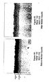
Figures 1A and 1B are photomicrographs at 500X of CMSX-4 nickel base superalloy samples before immersion and after immersion in a caustic inorganic hydroxide bath pursuant to the present invention. -
Figures 2A and 2B are photomicrographs at 500X of Rene' N5 nickel base superalloy sample before immersion and after immersion in a caustic inorganic hydroxide bath pursuant to the present invention. -
Figures 3A and 3B are photomicrographs at 500X of CMSX-4 nickel base superalloy samples coated with a thermal barrier coating before immersion and after immersion in a caustic inorganic hydroxide bath pursuant to the present invention. -
Figures 4A and 4B are photomicrographs at 500X of Rene 142 nickel base superalloy samples coated with a CVD low activity diffusion aluminide before immersion and after immersion in a caustic inorganic hydroxide bath pursuant to the present invention. -
Figure 5 is an X-ray spectra of the surface of a platinum modified diffusion aluminide surface of a Rene' N5 button sample after immersion in a molten caustic KOH bath. - The present invention involves a chemical method of removing a ceramic thermal barrier coating from a superalloy and other substrates of a wide variety of configurations at ambient pressure and in very short times without damage to the substrate or any bondcoat thereon.
- The thermal barrier coating typically comprises an outer ceramic thermal insulating coating or
layer 10 disposed on anintermediate oxide layer 12 comprising for example only, an alumina layer, chromia layer, and the like,Figure 3A . Theintermediate oxide layer 12 is formed or deposited on aninner bondcoat layer 14 which may comprise a metallic layer, such as an MCrA1Y alloy overlay where M is nickel and/or cobalt, and/or a diffusion aluminide layer which may be modified by inclusion of Pt or other precious metal(s) and other elemental additions, such as reactive metals including Si, Hf, Y, and/or Zr and alkali and alkaline earth metals, such as K and Mg. - The intermediate layer can be formed by oxidation of the bondcoat by heating in an oxidizing atmosphere to thermally grow the layer thereon as a thin oxide layer. Alternately, the intermediate layer can be deposited by chemical vapor deposition on the bondcoat as a thin layer of ceramic material.
- The MCrA1Y layer can be deposited on the substrate S by plasma spray, flame spraying, electron-beam-physical vapor deposition, sputtering and other known techniques. The diffusion aluminide layer can be formed on the substrate by chemical vapor deposition (CVD), pack cementation, above-the-pack, slurry and other known deposition techniques. The bondcoat layer typically ranges in thickness from about 25.4 µm (1 mil) to about 254 µm (10 mils), such as about 127 to about 203.2 µm (5 to about 8 mils) for MCrA1Y and about 25.4 µm to about 76.2 µm (1 to about 3 mils) for diffusion aluminide, for purposes of illustration and not limitation. If the substrate comprises an alumina forming alloy, the bondcoat may be omitted, or alumina may be applied to the substrate as a layer sans bondcoat.
- The outer thermal insulating layer comprises a ceramic material such as zirconia, alumina, and others known for use as thermal barrier layers. The ceramic thermal barrier material may be modified to include other ceramic materials such as yttria, ceria, scandia, magnesia, and similar materials. The thermal insulating layer may be a graded layer that changes composition from the outer free surface thereof to the inner surface thereof proximate the next inner layer (e.g. intermediate layer or bondcoat) or the substrate. The thermal insulating layer typically is applied or deposited by air plasma spray or electron beam physical vapor deposition (EB PVD) at suitable elevated substrate coating temperatures. When applied by ED PVD, the thermal insulating layer exhibits a microstructure of columnar grains extending generally perpendicular to the bondcoat and substrate surface,
Fig. 3A . The thermal insulating layer typically ranges in thickness from about 50.8 µm (2 mils) to about 508 µm (20 mils) for purposes of illustration only. - The substrate S can comprise nickel, cobalt or iron base superalloys in cast or wrought form commonly used for gas turbine engine components, such as turbine blades and vanes, nozzle guide vanes. Examples of common superalloy and other substrates to which the invention is applicable include, but are not limited to, single crystal and directionally solidified superalloys such as CMSX-4, PWA-1484, Rene' N5, Rene'142, PWA-1480, and CM-186LC and other high temperature polycrystalline alloys such as Rene'80, GTD-111 and IN-738 for purposes of illustration only. The substrate can have a wide variety of configurations such as complex turbine blade and vane shapes, simple flat or curvilinear shapes, and other myriad shapes.
- Thermal barrier coatings, as discussed or mentioned herein, are well known and described in such patents as
U.S. Patent 4 405 659 ;4 676 994 ;5 015 502 ;5 514 482 and5 716 720 for example. - Pursuant to an embodiment of the invention, an engine-run or other thermal barrier coated component, such as a superalloy turbine blade, vane and other component, is subjected to a refurbishment or repair operation wherein the
thermal barrier coating 10 is removed from the component (substrate) without significant chemical attack or other damage to the component substrate or anybondcoat 14 thereon by a chemical removal method at ambient pressure and in very short times as compared to prior art techniques described above without damage to the substrate or any bondcoat thereon. - In an illustrative embodiment of the present invention, the component having the used
thermal barrier coating 10 is immersed in an inorganic hydroxide liquid bath having a high concentration of alkali or alkaline earth hydroxide, such as KOH, NaOH, Ca(OH)2, Mg(OH)2 with the bath at ambient (atmospheric) pressure and elevated temperature, such as for example only at about 135 °C (275 degrees F) and above, for a time sufficient to effect detachment of thethermal barrier coating 10 for removal from the substrate and bondcoat. - An exemplary hydroxide liquid bath comprises an inorganic hydroxide solution or liquid having at least about 50 weight %, preferably at least 80 weight %, of an alkali or alkaline earth hydroxide and the balance essentially water. For purposes of further illustration and not limitation, the inorganic hydroxide bath preferably can comprise 90 weight % KOH and 10 weight % water at 343 °C (650 degrees F) disposed in a vessel open to atmospheric pressure. Water is added to the bath as necessary during use to replenish water lost by evaporation. The component having the
thermal barrier coating 10 thereon can be immersed in the bath for a short time (e.g. about 15 seconds to several minutes) to detach the thermal barrier coating, via preferential chemical attack/dissolutsion of theintermediate oxide layer 12 located between the bondcoat and the thermal barrier coating, without damage to the substrate or any bondcoat present thereon and then immersed in the water bath to remove any minor thermal barrier coating clinging to the substrate and any bondcoat present thereon. In particular, the hot component is removed from the hot caustic bath after a selected time and immersed in a water bath whereby the water bath is heated by the hot component and boiled/agitated to facilitate removal of any remaining, clinging thermal barrier coating from the substrate. - The present invention was demonstrated using a beaker (capacity of one liter) disposed on a laboratory bench in air wrapped in a Kaowool thermal insulation inner blanket and an outer wrapping of aluminum foil. A thermocouple was inserted between the beaker and the thermal insulation to monitor temperature of the caustic bath.
- A watch glass was placed on the top of the beaker to permit viewing of the thermal barrier coating removal process. The beaker was filled with a metal hydroxide flake, particularly hydrated KOH flake (90% KOH-10% water by weight), and was heated by electrical resistance to produce a molten bath at 343 °C (650 degrees F). The thermal barrier coated samples described below were submerged in the molten KOH bath until the thermal barrier coating started to fragment and peel off the part by virtue of preferential chemical attack or dissolution of the alumina or
other oxide layer 12 located between the bondcoat and thermal barrier coating, removing substantially all of the thermal barrier coating. At this point in the process, the hot part was removed from the molten KOH bath and rinsed in a room temperature water bath by immersion therein. The hot component caused localized boiling of water in contact therewith and facilitated removal of remaining minor amount of thermal barrier coating which had not previously fallen off the part in the bath. - The chemical removal procedure was conducted on numerous substrate alloys. In particular, a first test was performed using CMSX-4, PWA-1484, and Rene' N5 substrate samples without any coating to determine effect of the above molten KOH bath (90% KOH-10 % water by weight) in air on the substrates. The base alloy samples were submerged in the molten KOH bath for 9 minutes and then rinsed in room temperature water as described above. Figures IA and 1B are photomicrographs at 500X of CMSX-4 nickel base superalloy samples before immersion and after immersion in the molten KOH bath.
Figures 2A and 2B are photomicrographs at 500X of Rene N5 nickel base superalloy sample before immersion and after immersion in the molten KOH bath. These Figures indicate that there was no harmful base metal attack from the treatment. The same results were obtained using uncoated PWA-1484 base metal samples. The chemical removal procedure also was conducted on CMSX-4 substrate alloy (a solid turbine blade) samples coated with a yttria stabilized zirconia thermal barrier coating of about 127 µm (0.005 inch) thickness and a bondcoat of platinum modified diffusion aluminide designated MDC-150L described inUS Patent 5 716 720 having a thickness of about 50.8 µm (0.002 inch). One sample was submerged for approximately two minutes in the above molten KOH bath (90% KOH-10% water by weight) in air and then rinsed in the water bath. - The other sample was submerged in the above molten KOH bath in air for 15 minutes to further investigate the effect of the molten KOH bath on attack of the bondcoat.
Figures 3A and 3B are photomicrographs at 500X of CMSX-4 nickel base superalloy samples coated with a thermal barrier coating before immersion and after simmersion in the molten bath. Removal of thethermal barrier coating 10 without base metal attack or bondcoat attack is evident from these Figures. - The chemical removal procedure also was conducted on a Rene'142 substrate alloy (a hollow turbine blade) sample coated with a CVD low activity diffusion aluminide designated MDC 210 having a total thickness of about 25.4 µm (0.001 inch). The low activity diffusion coating comprises an additive NiAl
outer layer 22 and an inner refractory elementrich diffusion zone 24 adjacent substrate S. The sample was submerged for approximately nine minutes in the above molten KOH bath (90% KOH-10% water by weight) in air and then rinsed in the water bath.Figures 4A and 4B are photomicrographs at 500X of the Rene'142 sample coated with the CVD low activity aluminide coating before immersion and after immersion in the molten KOH bath. These Figures indicate that there was no harmful attack of the simple aluminide diffusion coating by the treatment. - The present invention also involves a thermal barrier recoated component that exhibits improved resistance to oxidation following removal of the used thermal barrier coating pursuant to the present invention and recoating with a fresh thermal barrier coating. In particular, by virtue of removal of the used thermal barrier coating in the aforementioned caustic bath, the alkali or alkaline earth element of the caustic bath has been discovered to remain on the surface of the stripped component (either on the bondcoat or on the superalloy substrate if no bondcoat is present) in a detectable amount and to become incorporated in the bondcoat (or superalloy substrate) when the fresh thermal barrier coating is applied to the stripped component at elevated temperature in an amount effective to increase oxidation resistance of the bondcoat (or superalloy substrate) and thus the recoated component having the thermal barrier coating thereon. The bondcoat, if present can comprise an aluminide, MrCrAlY, or other bondcoat.
- For purposes of illustration, two separate sets of samples were involved in the above chemical removal procedure to demonstrate that the alkali or alkaline earth element of the caustic bath remains on the surface of the stripped component. In particular, one set of samples included CF6-80C2 first stage turbine blades that were made of Rene' N5 superalloy and that are designed by the engine manufacturer to be air cooled in service by internal serpentine passages with numerous surface film cooling holes. The other set of samples included one inch diameter buttons comprised of Rene' N5 superalloy.
- Two different CVD low activity platinum diffusion aluminide coatings were used in this demonstration. Namely, the aforementioned turbine blade samples were Pt electroplated in a KOH electroplating solution as described in Serial No.
08/685,379 , issued asU.S. Patent 5 788 823 , aluminized by CVD low activity as described inU.S. Patent 5 568 614 to provide a platinum modified diffusion aluminide coating having a thickness of 63.5 µm (0.0025 inch), and thermal barrier coated as described inU.S. Patent 5 716 720 to provide a yttria stabilized zirconia thermal barrier coating having a thickness of 127 µm (0.005 inch) on the aluminide bondcoat. Theintermediate alumina layer 12 was formed by high temperature exposure to an oxidizing atmosphere. - The aforementioned button samples were Pt electroplated as described in
U.S. Patent 3 677 789 using a phosphate electroplating bath and CVD aluminized as described inU.S. Patent 5 658 614 to form a platinum modified diffusion aluminide coating having a thickness of 63.5 µm (0.0025 inch). No TBC coating was applied to the aluminide coating. - The coatings on the turbine blade samples already contained potassium from the potassium hydroxide Pt plating process, and so, were not suitable samples to show potassium pick-up by the above chemical removal procedure for removing the thermal barrier coating.
- One coated turbine blade sample and one coated button sample were submerged for approximately 7 minutes in the above molten KOH caustic bath (90 weight % KOH and 10 weight % water) at 343 °C (650 degrees F) in air and then rinsed in the water bath. Then, the stripped turbine blade sample was recoated with a fresh yttria stabilized zirconia thermal barrier coating (TBC) as described above.
- A coated turbine blade sample without the above caustic bath chemical removal treatment (i.e. having the original TBC coating thereon) and with the above caustic bath chemical removal treatment and recoated with the fresh yttria stabilized zirconia TBC coating were oxidation tested at 1135 °C (2075 degrees F) using one hour cycles with each cycle comprising 50 minutes at temperature and 10 minutes air cooling. Spalling of 20% of the TBC coating was defined as failure in this testing. The coated turbine blade sample with the above caustic bath chemical removal treatment and recoated with the fresh TBC coating exhibited more than a 4 times improvement in life in the oxidation test in comparison with the aforementioned non-KOH treated and TBC coated blade.
- Following the above caustic bath chemical removal treatment, the surface of the Rene' N5 button samples were examined for potassium pickup using an energy dispersive X-ray spectrometer (EDS) on a scanning electron microscope (SEM).
Figure 5 is the resulting EDS spectra for a sample and demonstrates detectable potassium pickup on and/or in the platinum modified diffusion aluminide from the hot KOH treatment bath. In view of the teachings of Serial No.08/685,379 , issued asU.S. Patent 5 788 823 , an improvement in the oxidation resistance of the platinum modified diffusion aluminide bond coating and thus the TBC coated blade is expected from the incorporation of potassium in the aluminide coating during the hot KOH chemical removal treatment pursuant to the present invention and after TBC coating thereof at elevated temperature. - The present invention is advantageous to remove ceramic thermal barrier coatings from superalloy and other substrates of a wide variety of configurations at ambient pressure and in very short times without detectable or harmful damage to the substrate or any bondcoat thereon. The process is economical with process cycle times generally less than a few minutes and low capital cost for equipment. The invention can replace traditional thermal barrier coating removal processes such as water jet, shot peening, HF cleaning, and caustic autoclave treatment with substantially shorter cycle times (e.g. a few minutes of the invention versus 8 hours for caustic autoclave) without the energy intensive and manual labor requirements for these methods. Moreover, the present invention provides a thermal barrier recoated component that exhibits improved resistance to oxidation following removal of the used thermal barrier coating pursuant to the present invention and recoating with a fresh thermal barrier coating.
Claims (13)
- Use of a method for removing a thermal barrier coating from a superalloy substrate preferably having a bondcoat thereon with an inorganic hydroxide liquid bath comprising at least 50 weight % of an alkali or alkaline earth hydroxide at ambient pressure and elevated temperature for providing at least one of the substrate and said bondcoat with an element selected from the group consisting of alkali and alkaline earth in an amount effective to increase the oxidation resistance of at least one of said substrate and said bondcoat.
- Use of the method of claim 1 wherein said bondcoat is selected from the group consisting of an aluminide and an MCrAlY alloy wherein M is nickel and/or cobalt.
- Use of the method of claim 1 or 2 wherein a thermal barrier coating is applied onto the oxidation resistance improved component.
- Use of the method of one of claims 1 to 3 wherein a used thermal barrier coating is removed from the substrate having an additional layer between the thermal barrier coating and the substrate, said method comprising contacting said thermal barrier coated substrate and said hydroxide bath with the bath at ambient pressure and elevated temperature for a time sufficient to effect detachment of the thermal barrier coating from the substrate, wherein said additional layer comprises an intermediate oxide layer comprising alumina or chromia and the constituents of said bath and of said intermediate oxide layer are selected such that detachment of the thermal barrier coating from the substrate is effected by attacking by said bath at least the first one of said additional layer and said thermal barrier coating.
- Use of the method of claim 4 wherein said intermediate layer is disposed between a bondcoat on the substrate and said thermal barrier coating.
- Use of the method of claim 4 or 5 wherein the hydroxide bath comprises said at least 50 weight % of an alkali or alkaline earth hydroxide and the balance essentially water.
- Use of the method of one of claims 1 to 6 wherein the hydroxide bath comprises about 90 weight % of an alkali or alkaline earth hydroxide and the balance essentially water.
- Use of the method of one of claims 1 to 7 wherein the hydroxide bath is at a temperature of at least about 135°C (275 degrees F).
- Use of the method of one of claims 1 to 8 wherein the thermal barrier coating is contacted with the hydroxide bath for at least 15 seconds.
- Use of the method of one of claims 1 to 9 further including the step of contacting the substrate and a water bath at a lower temperature than the temperature of said hydroxide bath following treatment in said hydroxide bath.
- Use of the method of one of claims 1 to 10 wherein the thermal barrier coated substrate is immersed in a vessel having said hydroxide bath therein and open to ambient atmosphere.
- Use of the method of one of claims 1 to 11 wherein at least one of alkali and alkaline earth element from the hydroxide bath remains on a surface of the substrate or a bondcoat thereon after the thermal barrier coating is removed.
- Use of the method of one of claims 1 to 12 including the further step of coating the substrate after removal of the thermal barrier coating with a fresh thermal barrier coating so that said at least one of alkali and alkaline earth element is incorporated in the substrate or bondcoat.
Applications Claiming Priority (2)
| Application Number | Priority Date | Filing Date | Title |
|---|---|---|---|
| US09/126,583 US6132520A (en) | 1998-07-30 | 1998-07-30 | Removal of thermal barrier coatings |
| EP99935922A EP1107867B1 (en) | 1998-07-30 | 1999-07-26 | Removal of thermal barrier coatings |
Related Parent Applications (1)
| Application Number | Title | Priority Date | Filing Date |
|---|---|---|---|
| EP99935922A Division EP1107867B1 (en) | 1998-07-30 | 1999-07-26 | Removal of thermal barrier coatings |
Publications (2)
| Publication Number | Publication Date |
|---|---|
| EP1956116A1 EP1956116A1 (en) | 2008-08-13 |
| EP1956116B1 true EP1956116B1 (en) | 2015-10-14 |
Family
ID=22425627
Family Applications (2)
| Application Number | Title | Priority Date | Filing Date |
|---|---|---|---|
| EP08008023.7A Expired - Lifetime EP1956116B1 (en) | 1998-07-30 | 1999-07-26 | Removal of thermal barrier coatings |
| EP99935922A Expired - Lifetime EP1107867B1 (en) | 1998-07-30 | 1999-07-26 | Removal of thermal barrier coatings |
Family Applications After (1)
| Application Number | Title | Priority Date | Filing Date |
|---|---|---|---|
| EP99935922A Expired - Lifetime EP1107867B1 (en) | 1998-07-30 | 1999-07-26 | Removal of thermal barrier coatings |
Country Status (5)
| Country | Link |
|---|---|
| US (1) | US6132520A (en) |
| EP (2) | EP1956116B1 (en) |
| JP (1) | JP4681733B2 (en) |
| DE (1) | DE69940203D1 (en) |
| WO (1) | WO2000006380A1 (en) |
Families Citing this family (25)
| Publication number | Priority date | Publication date | Assignee | Title |
|---|---|---|---|---|
| US6472018B1 (en) * | 2000-02-23 | 2002-10-29 | Howmet Research Corporation | Thermal barrier coating method |
| US6475289B2 (en) * | 2000-12-19 | 2002-11-05 | Howmet Research Corporation | Cleaning of internal passages of airfoils |
| EP1251191B1 (en) | 2001-04-21 | 2004-06-02 | ALSTOM Technology Ltd | A method of repairing a ceramic coating |
| US6820335B2 (en) * | 2001-10-16 | 2004-11-23 | United Technologies Corporation | Component bonding process |
| DE60310168T2 (en) * | 2002-08-02 | 2007-09-13 | Alstom Technology Ltd. | Method for protecting partial surfaces of a workpiece |
| EP1411149A1 (en) * | 2002-10-18 | 2004-04-21 | Siemens Aktiengesellschaft | Process for stripping coatings from components |
| US20050123785A1 (en) * | 2003-12-04 | 2005-06-09 | Purusottam Sahoo | High temperature clearance coating |
| US6878215B1 (en) | 2004-05-27 | 2005-04-12 | General Electric Company | Chemical removal of a metal oxide coating from a superalloy article |
| EP1676938A1 (en) * | 2004-12-30 | 2006-07-05 | Siemens Aktiengesellschaft | Method of manufacturing a component part of a turbine and a component of a turbine |
| DE102005049249B4 (en) * | 2005-10-14 | 2018-03-29 | MTU Aero Engines AG | Process for stripping a gas turbine component |
| DE102007022832A1 (en) * | 2007-05-15 | 2008-11-20 | Mtu Aero Engines Gmbh | Process for stripping a component |
| DE102008005168A1 (en) * | 2008-01-19 | 2009-07-23 | Mtu Aero Engines Gmbh | A method of at least selectively removing a first layer of an engine component |
| US7927714B2 (en) * | 2008-08-20 | 2011-04-19 | The Trustees Of Princeton University | Barium-doped bond coat for thermal barrier coatings |
| CN102062121B (en) | 2010-09-16 | 2013-03-27 | 格兰富水泵(苏州)有限公司 | Axial flow impeller |
| CN102418110B (en) * | 2010-09-26 | 2015-06-10 | 通用电气公司 | Method for removing oxides |
| US20120328445A1 (en) * | 2011-06-27 | 2012-12-27 | United Technologies Corporation | Grit blast free thermal barrier coating rework |
| US10196929B2 (en) | 2012-06-30 | 2019-02-05 | General Electric Company | Process for depositing a ceramic coating and product formed thereof |
| US10363584B2 (en) * | 2013-08-30 | 2019-07-30 | General Electric Company | Methods for removing barrier coatings, bondcoat and oxide layers from ceramic matrix composites |
| GB201318873D0 (en) | 2013-10-25 | 2013-12-11 | Rolls Royce Plc | Thermal barrier coating removal process |
| CN105420744A (en) * | 2015-11-20 | 2016-03-23 | 沈阳黎明航空发动机(集团)有限责任公司 | Method for removing ceramic surface layer of thermal barrier coating of turbine blade |
| US9803139B1 (en) * | 2016-06-24 | 2017-10-31 | General Electric Company | Process for removing aluminum-silicon coatings from metallic structures, and related processes for preparing magnetic components |
| GB201903484D0 (en) | 2019-03-14 | 2019-05-01 | Rolls Royce Plc | A method of removing a ceramic coating from a ceramic coated metallic article |
| US11970953B2 (en) | 2019-08-23 | 2024-04-30 | Rtx Corporation | Slurry based diffusion coatings for blade under platform of internally-cooled components and process therefor |
| US11926880B2 (en) | 2021-04-21 | 2024-03-12 | General Electric Company | Fabrication method for a component having magnetic and non-magnetic dual phases |
| US11661646B2 (en) | 2021-04-21 | 2023-05-30 | General Electric Comapny | Dual phase magnetic material component and method of its formation |
Family Cites Families (25)
| Publication number | Priority date | Publication date | Assignee | Title |
|---|---|---|---|---|
| DE1796175C2 (en) | 1968-09-14 | 1974-05-30 | Deutsche Edelstahlwerke Gmbh, 4150 Krefeld | High temperature corrosion and scaling resistant diffusion protection layer on objects made of high temperature alloys based on nickel and / or cobalt |
| US4073662A (en) * | 1977-03-09 | 1978-02-14 | General Electric Company | Method for removing a magnesia doped alumina core material |
| US4405659A (en) | 1980-01-07 | 1983-09-20 | United Technologies Corporation | Method for producing columnar grain ceramic thermal barrier coatings |
| GB2084895A (en) * | 1980-10-04 | 1982-04-21 | Rolls Royce | Dissolving refractory materials in particular cores from castings |
| GB2126931B (en) * | 1982-09-04 | 1986-04-23 | Rolls Royce | Dissolving ceramic materials |
| US4676994A (en) | 1983-06-15 | 1987-06-30 | The Boc Group, Inc. | Adherent ceramic coatings |
| US5514482A (en) | 1984-04-25 | 1996-05-07 | Alliedsignal Inc. | Thermal barrier coating system for superalloy components |
| US4576874A (en) * | 1984-10-03 | 1986-03-18 | Westinghouse Electric Corp. | Spalling and corrosion resistant ceramic coating for land and marine combustion turbines |
| US4566939A (en) * | 1985-01-25 | 1986-01-28 | Avco Corporation | Surface preparation of nickel base alloys for brazing |
| DE3523961A1 (en) * | 1985-07-04 | 1987-01-15 | Licentia Gmbh | DEVICE FOR TREATING AT LEAST ONE CERAMIC ITEM IN AN ALKALINE HYDROXIDE MELT |
| US4889589A (en) * | 1986-06-26 | 1989-12-26 | United Technologies Corporation | Gaseous removal of ceramic coatings |
| US5028385A (en) * | 1989-04-10 | 1991-07-02 | Baldi Alfonso L | Treatment of metals for coating or activation |
| US5015502A (en) | 1988-11-03 | 1991-05-14 | Allied-Signal Inc. | Ceramic thermal barrier coating with alumina interlayer |
| GB2266677B (en) * | 1992-05-08 | 1995-02-01 | Rolls Royce Plc | Improvements in or relating to the leaching of ceramic materials |
| JP3117808B2 (en) * | 1992-09-25 | 2000-12-18 | 日産自動車株式会社 | Coating removal method |
| US5507306A (en) * | 1993-12-23 | 1996-04-16 | Howmet Corporation | Cleaning apparatus and method for cleaning internal airfoil cooling passages |
| US5568614A (en) | 1994-07-29 | 1996-10-22 | International Business Machines Corporation | Data streaming between peer subsystems of a computer system |
| US5679270A (en) * | 1994-10-24 | 1997-10-21 | Howmet Research Corporation | Method for removing ceramic material from castings using caustic medium with oxygen getter |
| US5658614A (en) | 1994-10-28 | 1997-08-19 | Howmet Research Corporation | Platinum aluminide CVD coating method |
| US5614054A (en) * | 1994-12-22 | 1997-03-25 | General Electric Company | Process for removing a thermal barrier coating |
| US5716720A (en) | 1995-03-21 | 1998-02-10 | Howmet Corporation | Thermal barrier coating system with intermediate phase bondcoat |
| US5678583A (en) * | 1995-05-22 | 1997-10-21 | Howmet Research Corporation | Removal of ceramic shell mold material from castings |
| US5685917A (en) * | 1995-12-26 | 1997-11-11 | General Electric Company | Method for cleaning cracks and surfaces of airfoils |
| US5643474A (en) * | 1995-12-26 | 1997-07-01 | General Electric Company | Thermal barrier coating removal on flat and contoured surfaces |
| US5788823A (en) * | 1996-07-23 | 1998-08-04 | Howmet Research Corporation | Platinum modified aluminide diffusion coating and method |
-
1998
- 1998-07-30 US US09/126,583 patent/US6132520A/en not_active Expired - Lifetime
-
1999
- 1999-07-26 EP EP08008023.7A patent/EP1956116B1/en not_active Expired - Lifetime
- 1999-07-26 WO PCT/US1999/016894 patent/WO2000006380A1/en not_active Ceased
- 1999-07-26 JP JP2000562210A patent/JP4681733B2/en not_active Expired - Lifetime
- 1999-07-26 DE DE69940203T patent/DE69940203D1/en not_active Expired - Lifetime
- 1999-07-26 EP EP99935922A patent/EP1107867B1/en not_active Expired - Lifetime
Also Published As
| Publication number | Publication date |
|---|---|
| EP1107867A1 (en) | 2001-06-20 |
| EP1956116A1 (en) | 2008-08-13 |
| US6132520A (en) | 2000-10-17 |
| JP4681733B2 (en) | 2011-05-11 |
| DE69940203D1 (en) | 2009-02-12 |
| WO2000006380A1 (en) | 2000-02-10 |
| EP1107867A4 (en) | 2002-11-20 |
| JP2002521568A (en) | 2002-07-16 |
| EP1107867B1 (en) | 2008-12-31 |
Similar Documents
| Publication | Publication Date | Title |
|---|---|---|
| EP1107867B1 (en) | Removal of thermal barrier coatings | |
| JP4942926B2 (en) | Method of repairing a part using an environmental bond film and the resulting repaired part | |
| JP5036965B2 (en) | Method of repairing coated parts using NiAl bonding coat | |
| US6042898A (en) | Method for applying improved durability thermal barrier coatings | |
| US5942337A (en) | Thermal barrier coating for a superalloy article and a method of application thereof | |
| US6255001B1 (en) | Bond coat for a thermal barrier coating system and method therefor | |
| JP6126852B2 (en) | Gas turbine component coating and coating method | |
| CA2330218C (en) | Method of removing a thermal barrier coating | |
| US6572981B2 (en) | Thermal barrier coating system with improved aluminide bond coat and method therefor | |
| EP1167575A2 (en) | Nickel aluminide coating and coating systems formed therewith | |
| EP0808913A1 (en) | Method for repairing a thermal barrier coating | |
| US20100266417A1 (en) | Bond coat with low deposited aluminum level and method therefore | |
| US6974636B2 (en) | Protective coating for turbine engine component | |
| US5614054A (en) | Process for removing a thermal barrier coating | |
| JP2005147149A (en) | How to repair coated parts | |
| US5900102A (en) | Method for repairing a thermal barrier coating | |
| US6174448B1 (en) | Method for stripping aluminum from a diffusion coating | |
| US5851409A (en) | Method for removing an environmental coating | |
| EP1013786A1 (en) | Method for repairing a superalloy turbine component | |
| JP4579383B2 (en) | Method for removing dense ceramic thermal barrier coating from surface | |
| US6447932B1 (en) | Substrate stabilization of superalloys protected by an aluminum-rich coating | |
| US6475289B2 (en) | Cleaning of internal passages of airfoils | |
| EP1123987A1 (en) | Repairable diffusion aluminide coatings | |
| WO2005038074A1 (en) | Method of applying a thermal barrier coating system to a superalloy substrate | |
| Warnes et al. | Molten metal hydroxide removal of thermal barrier coatings |
Legal Events
| Date | Code | Title | Description |
|---|---|---|---|
| PUAI | Public reference made under article 153(3) epc to a published international application that has entered the european phase |
Free format text: ORIGINAL CODE: 0009012 |
|
| 17P | Request for examination filed |
Effective date: 20080425 |
|
| AC | Divisional application: reference to earlier application |
Ref document number: 1107867 Country of ref document: EP Kind code of ref document: P |
|
| AK | Designated contracting states |
Kind code of ref document: A1 Designated state(s): DE FR GB |
|
| 17Q | First examination report despatched |
Effective date: 20081103 |
|
| AKX | Designation fees paid |
Designated state(s): DE FR GB |
|
| RAP1 | Party data changed (applicant data changed or rights of an application transferred) |
Owner name: HOWMET CORPORATION |
|
| GRAP | Despatch of communication of intention to grant a patent |
Free format text: ORIGINAL CODE: EPIDOSNIGR1 |
|
| INTG | Intention to grant announced |
Effective date: 20150511 |
|
| GRAS | Grant fee paid |
Free format text: ORIGINAL CODE: EPIDOSNIGR3 |
|
| GRAA | (expected) grant |
Free format text: ORIGINAL CODE: 0009210 |
|
| AC | Divisional application: reference to earlier application |
Ref document number: 1107867 Country of ref document: EP Kind code of ref document: P |
|
| AK | Designated contracting states |
Kind code of ref document: B1 Designated state(s): DE FR GB |
|
| REG | Reference to a national code |
Ref country code: GB Ref legal event code: FG4D |
|
| REG | Reference to a national code |
Ref country code: DE Ref legal event code: R096 Ref document number: 69945420 Country of ref document: DE |
|
| REG | Reference to a national code |
Ref country code: DE Ref legal event code: R097 Ref document number: 69945420 Country of ref document: DE |
|
| REG | Reference to a national code |
Ref country code: FR Ref legal event code: PLFP Year of fee payment: 18 |
|
| PLBE | No opposition filed within time limit |
Free format text: ORIGINAL CODE: 0009261 |
|
| STAA | Information on the status of an ep patent application or granted ep patent |
Free format text: STATUS: NO OPPOSITION FILED WITHIN TIME LIMIT |
|
| 26N | No opposition filed |
Effective date: 20160715 |
|
| REG | Reference to a national code |
Ref country code: FR Ref legal event code: PLFP Year of fee payment: 19 |
|
| REG | Reference to a national code |
Ref country code: FR Ref legal event code: PLFP Year of fee payment: 20 |
|
| PGFP | Annual fee paid to national office [announced via postgrant information from national office to epo] |
Ref country code: DE Payment date: 20180723 Year of fee payment: 20 Ref country code: FR Payment date: 20180725 Year of fee payment: 20 |
|
| PGFP | Annual fee paid to national office [announced via postgrant information from national office to epo] |
Ref country code: GB Payment date: 20180719 Year of fee payment: 20 |
|
| REG | Reference to a national code |
Ref country code: DE Ref legal event code: R071 Ref document number: 69945420 Country of ref document: DE |
|
| REG | Reference to a national code |
Ref country code: GB Ref legal event code: PE20 Expiry date: 20190725 |
|
| PG25 | Lapsed in a contracting state [announced via postgrant information from national office to epo] |
Ref country code: GB Free format text: LAPSE BECAUSE OF EXPIRATION OF PROTECTION Effective date: 20190725 |