EP1955861A1 - Method and apparatus for printing on rigid panels and countoured or textured surfaces - Google Patents
Method and apparatus for printing on rigid panels and countoured or textured surfaces Download PDFInfo
- Publication number
- EP1955861A1 EP1955861A1 EP08075214A EP08075214A EP1955861A1 EP 1955861 A1 EP1955861 A1 EP 1955861A1 EP 08075214 A EP08075214 A EP 08075214A EP 08075214 A EP08075214 A EP 08075214A EP 1955861 A1 EP1955861 A1 EP 1955861A1
- Authority
- EP
- European Patent Office
- Prior art keywords
- substrate
- ink
- printhead
- carriage
- curing
- Prior art date
- Legal status (The legal status is an assumption and is not a legal conclusion. Google has not performed a legal analysis and makes no representation as to the accuracy of the status listed.)
- Withdrawn
Links
Images



Classifications
-
- B—PERFORMING OPERATIONS; TRANSPORTING
- B41—PRINTING; LINING MACHINES; TYPEWRITERS; STAMPS
- B41J—TYPEWRITERS; SELECTIVE PRINTING MECHANISMS, i.e. MECHANISMS PRINTING OTHERWISE THAN FROM A FORME; CORRECTION OF TYPOGRAPHICAL ERRORS
- B41J25/00—Actions or mechanisms not otherwise provided for
- B41J25/304—Bodily-movable mechanisms for print heads or carriages movable towards or from paper surface
- B41J25/308—Bodily-movable mechanisms for print heads or carriages movable towards or from paper surface with print gap adjustment mechanisms
-
- B—PERFORMING OPERATIONS; TRANSPORTING
- B41—PRINTING; LINING MACHINES; TYPEWRITERS; STAMPS
- B41J—TYPEWRITERS; SELECTIVE PRINTING MECHANISMS, i.e. MECHANISMS PRINTING OTHERWISE THAN FROM A FORME; CORRECTION OF TYPOGRAPHICAL ERRORS
- B41J11/00—Devices or arrangements of selective printing mechanisms, e.g. ink-jet printers or thermal printers, for supporting or handling copy material in sheet or web form
- B41J11/0015—Devices or arrangements of selective printing mechanisms, e.g. ink-jet printers or thermal printers, for supporting or handling copy material in sheet or web form for treating before, during or after printing or for uniform coating or laminating the copy material before or after printing
-
- B—PERFORMING OPERATIONS; TRANSPORTING
- B41—PRINTING; LINING MACHINES; TYPEWRITERS; STAMPS
- B41J—TYPEWRITERS; SELECTIVE PRINTING MECHANISMS, i.e. MECHANISMS PRINTING OTHERWISE THAN FROM A FORME; CORRECTION OF TYPOGRAPHICAL ERRORS
- B41J11/00—Devices or arrangements of selective printing mechanisms, e.g. ink-jet printers or thermal printers, for supporting or handling copy material in sheet or web form
- B41J11/0015—Devices or arrangements of selective printing mechanisms, e.g. ink-jet printers or thermal printers, for supporting or handling copy material in sheet or web form for treating before, during or after printing or for uniform coating or laminating the copy material before or after printing
- B41J11/002—Curing or drying the ink on the copy materials, e.g. by heating or irradiating
- B41J11/0021—Curing or drying the ink on the copy materials, e.g. by heating or irradiating using irradiation
- B41J11/00212—Controlling the irradiation means, e.g. image-based controlling of the irradiation zone or control of the duration or intensity of the irradiation
-
- B—PERFORMING OPERATIONS; TRANSPORTING
- B41—PRINTING; LINING MACHINES; TYPEWRITERS; STAMPS
- B41J—TYPEWRITERS; SELECTIVE PRINTING MECHANISMS, i.e. MECHANISMS PRINTING OTHERWISE THAN FROM A FORME; CORRECTION OF TYPOGRAPHICAL ERRORS
- B41J11/00—Devices or arrangements of selective printing mechanisms, e.g. ink-jet printers or thermal printers, for supporting or handling copy material in sheet or web form
- B41J11/0015—Devices or arrangements of selective printing mechanisms, e.g. ink-jet printers or thermal printers, for supporting or handling copy material in sheet or web form for treating before, during or after printing or for uniform coating or laminating the copy material before or after printing
- B41J11/002—Curing or drying the ink on the copy materials, e.g. by heating or irradiating
- B41J11/0021—Curing or drying the ink on the copy materials, e.g. by heating or irradiating using irradiation
- B41J11/00214—Curing or drying the ink on the copy materials, e.g. by heating or irradiating using irradiation using UV radiation
-
- B—PERFORMING OPERATIONS; TRANSPORTING
- B41—PRINTING; LINING MACHINES; TYPEWRITERS; STAMPS
- B41J—TYPEWRITERS; SELECTIVE PRINTING MECHANISMS, i.e. MECHANISMS PRINTING OTHERWISE THAN FROM A FORME; CORRECTION OF TYPOGRAPHICAL ERRORS
- B41J11/00—Devices or arrangements of selective printing mechanisms, e.g. ink-jet printers or thermal printers, for supporting or handling copy material in sheet or web form
- B41J11/0015—Devices or arrangements of selective printing mechanisms, e.g. ink-jet printers or thermal printers, for supporting or handling copy material in sheet or web form for treating before, during or after printing or for uniform coating or laminating the copy material before or after printing
- B41J11/002—Curing or drying the ink on the copy materials, e.g. by heating or irradiating
- B41J11/0021—Curing or drying the ink on the copy materials, e.g. by heating or irradiating using irradiation
- B41J11/00218—Constructional details of the irradiation means, e.g. radiation source attached to reciprocating print head assembly or shutter means provided on the radiation source
-
- B—PERFORMING OPERATIONS; TRANSPORTING
- B41—PRINTING; LINING MACHINES; TYPEWRITERS; STAMPS
- B41J—TYPEWRITERS; SELECTIVE PRINTING MECHANISMS, i.e. MECHANISMS PRINTING OTHERWISE THAN FROM A FORME; CORRECTION OF TYPOGRAPHICAL ERRORS
- B41J25/00—Actions or mechanisms not otherwise provided for
- B41J25/304—Bodily-movable mechanisms for print heads or carriages movable towards or from paper surface
- B41J25/308—Bodily-movable mechanisms for print heads or carriages movable towards or from paper surface with print gap adjustment mechanisms
- B41J25/3086—Bodily-movable mechanisms for print heads or carriages movable towards or from paper surface with print gap adjustment mechanisms with print gap adjustment means between the print head and its carriage
-
- B—PERFORMING OPERATIONS; TRANSPORTING
- B41—PRINTING; LINING MACHINES; TYPEWRITERS; STAMPS
- B41J—TYPEWRITERS; SELECTIVE PRINTING MECHANISMS, i.e. MECHANISMS PRINTING OTHERWISE THAN FROM A FORME; CORRECTION OF TYPOGRAPHICAL ERRORS
- B41J3/00—Typewriters or selective printing or marking mechanisms characterised by the purpose for which they are constructed
- B41J3/407—Typewriters or selective printing or marking mechanisms characterised by the purpose for which they are constructed for marking on special material
- B41J3/4073—Printing on three-dimensional objects not being in sheet or web form, e.g. spherical or cubic objects
-
- B—PERFORMING OPERATIONS; TRANSPORTING
- B41—PRINTING; LINING MACHINES; TYPEWRITERS; STAMPS
- B41J—TYPEWRITERS; SELECTIVE PRINTING MECHANISMS, i.e. MECHANISMS PRINTING OTHERWISE THAN FROM A FORME; CORRECTION OF TYPOGRAPHICAL ERRORS
- B41J11/00—Devices or arrangements of selective printing mechanisms, e.g. ink-jet printers or thermal printers, for supporting or handling copy material in sheet or web form
- B41J11/0015—Devices or arrangements of selective printing mechanisms, e.g. ink-jet printers or thermal printers, for supporting or handling copy material in sheet or web form for treating before, during or after printing or for uniform coating or laminating the copy material before or after printing
- B41J11/002—Curing or drying the ink on the copy materials, e.g. by heating or irradiating
- B41J11/0022—Curing or drying the ink on the copy materials, e.g. by heating or irradiating using convection means, e.g. by using a fan for blowing or sucking air
Definitions
- the present invention relates to printing onto rigid substrates, and to the printing onto textured, contoured or other three-dimensional substrates.
- the invention is particularly related to the printing onto such substrates as those having textile fabric surfaces or molded objects, rigid panels such as office partitions, automobile interior panels and other contoured objects, and to such printing using ink jet printing techniques.
- the velocity of the drops moving from the print head nozzles to the substrate declines with the distance traveled from the nozzles, and the paths of such drops become more greatly affected by air currents and other factors with increased nozzle to substrate distance.
- droplet shape changes the farther the drop moves from the nozzle, which changes the effects of the drop on the substrate. Accordingly, variations in the distance from the print head to the substrate can cause irregular effects on the printed image.
- Some substrates deform, even temporarily, when heated. Such deformation may be temporary, for example, where the material returns to its undetermed state when it cools. Nonetheless, even temporary deformation can adversely affect the print quality if it occurs when ink is being jetted onto the substrate.
- UV inks which is performed by exposing ink to UV immediately upon its contacting the substrate
- UV that is accompanied by heat producing radiation can deform substrates such as foam-board as the ink jets are making single or multiple passes over the print area.
- ink jet printing has not been successful on contoured materials and other three-dimensional substrates, particularly printing with UV curable inks in ink jet printing processes.
- An objective of the present invention is to provide for the printing onto three-dimensional substrates, particularly onto highly textured fabrics, tufted or irregular fabrics and other materials, contoured surfaces such as quilts, and mattress covers, and onto molded, stamped and otherwise shaped rigid or semi-rigid materials, and other three-dimensional surfaces.
- a particular objective of the invention is to print onto such surfaces with ink jet or digital printing processes.
- One more particular objective of the invention is to print onto such substrates with UV curable inks.
- printed images are applied to three-dimensional substrates with printing elements that are moveable relative to the plane of the substrate being printed.
- the invention provides a wide-substrate ink jet printing apparatus with print heads that move toward and away from the plane of a substrate to maintain a fixed distance between the nozzles of the printhead and the surface onto which the ink is being jetted. The variable distance over the plane of the substrate allows a controlled and uniform distance across which the ink is jetted.
- the printing element is an ink jet print head set having a plurality of heads, typically four, each for dispensing one of a set of colors onto the substrate to form a multi-colored image.
- one or more sensors is provided to measure the distance from the print head or from the print head carriage track to the point on the substrate on which ink is to be projected.
- the sensors generate reference signals that are fed to a controller that controls a servo motor on the print head carriage.
- the print head is moveably mounted to the carriage, for example on a ball screw mechanism, and is moveable toward and away from the plane of the substrate by operation of the servo motor.
- each print head of a set of four different color print heads is separately moveable relative to a common print head carriage, and is connected to one of a set of four servo motors by which its position relative to the plane of the substrate is capable of control relative to the positions of the other print heads.
- the print heads of the set are preferably arranged side by side in the transverse direction on the carriage so that one head follows the other across the width of the substrate as the carriage scans transversely across the substrate.
- Each head has a plurality of ink jet nozzles thereon for dispensing a given color of ink in a corresponding plurality of dots, for example 128 in number, that extend in a line transverse to the carriage, which is in a longitudinal direction perpendicular to the scan direction of the carriage.
- Two laser or optical sensors are provided on the carriage, one on each side of the heads, so that a distance measurement of the surface to the substrate can be taken ahead of the print heads when the heads are scanning in either direction.
- the controller records the contour of the substrate ahead of the print heads and varies the position of each print head, toward and away from the substrate plane, as each print head passes over the points at which the measurements were taken, so that each of the independently moveable heads follows the contour and maintains a fixed distance from the surface being printed.
- the substrate surface can alternatively be positioned relative to a print head that is maintained at a fixed vertical position on the frame.
- UV ink is printed onto material and the cure of the ink is initiated by exposure to UV light.
- UV curing lights may be mounted on the print head carriage, one on each side of the print head set, to expose the printed surface behind the heads.
- the jetted ink can be spot cured immediately upon contacting the substrate, which freezes the dots in position and prevents their spreading on or wicking into the substrate.
- conventional or broad spectrum UV curing lights include radiation that can heat the substrate. In the case of foam-board and several other commonly used substrates, the light heats the substrate and deforms it. Usually, this deposition is temporary in that the substrate blisters or swells when heated only to return to its original condition upon cooling.
- UV exposure is carried out downstream of the print head carriage, no harm results. But with spot curing, the substrate deforms at the point of printing, thereby adversely affecting the quality of the ink jet printing operation.
- a "cold UV” source or a source that includes a filter or other energy limiting device, for example, a limited bandwidth UV source, to prevent the energy from the source striking the substrate from carrying enough energy to heat the substrate. This may be done by providing sufficient UV energy at the relevant frequencies for curing the ink without heating the substrate.
- the invention is useful in printing onto substrates that can deform, even temporarily, when heated.
- the printed textile substrates or other textured or porous fabric is subjected to heat, preferably by blowing heated air onto the material downstream of the printing station, which extends the UV light initiated curing process and removes uncured components of the ink.
- UV curable ink is jetted onto the fabric and the jetted ink is exposed to UV curing light to cure the ink preferably to about 90 to 97% polymerization, with the fabric bearing the partially cured, jetted ink then heated in a hot air blower curing oven at which the UV light initiated polymerization continues, uncured monomers are vaporized, or both, in order to produce a printed image of UV ink that contains a low quantity of uncured monomer or other ink components, for example, less than 0.01%.
- UV ink is jetted onto a highly textured fabric such as a mattress cover ticking material
- the ink is jetted at a dot density of from about 180x254 dots per inch per color to about 300x300 dots per inch per color.
- four colors of a CMYK color palette are applied, each in drops or dots of, for example, about 75 picoliters, or approximately 80 nanograms, per drop, utilizing a UV ink jet print head.
- a UV curing light head is provided, which moves either with the print head or independent of the print head and exposes the deposited drops of UV ink with a beam of about 300 watts per linear inch, applying about 1 joule per square centimeter, thereby producing at least a 90% UV cure.
- the fabric on which the jetted ink has been thereby partially UV cured is then passed through an oven where it is heated to about 300°F for from about 30 seconds up to about three minutes. Forced hot air is preferably used to apply the heat in the oven, but other heating methods such as infrared or other radiant heaters may be used. Similar parameters may be used for cloth covered rigid panels such as office partitions.
- the distance from the print heads to the substrate where the ink is to be deposited can be determined by measuring the distance from a sensor to the substrate ahead of the print heads and mapping the location of the surface.
- a sensor to the substrate ahead of the print heads
- mapping the location of the surface For bidirectional print heads that move transversely across the longitudinally advancing fabric, providing two distance measuring sensors, one on each of the opposite sides of the print heads, are provided to measure the distance to the contoured fabric surface when the print heads are moving in either direction.
- a mechanical rolling sensor may be used, for example, by providing a pair of rollers, with one roller ahead of, and one head behind, the print head so that the average distance between the two rollers and a reference point on the print head can be used to control the distance of the print head from the plane of the substrate.
- one or more print heads can be mounted to a carriage having the rollers on the ends thereof so that the mechanical link between the rollers moves the print head relative to the plane of the substrate.
- a non-contact sensor such as a laser or photo eye sensor, is preferred in lieu of each roller.
- the outputs of two sensors on opposite sides of the print heads can be communicated to a processor, to measure the distance from the heads to the fabric ahead of the bidirectional heads, to drive a servo motor connected to the print head to raise and lower the head relative to the substrate plane so that the print heads move parallel to the contoured surface and jet ink onto the fabric across a fixed distance.
- Fig. 1 illustrates a machine 10 for printing onto rigid panels.
- the machine 10 includes a stationary frame 11 with a longitudinal extent represented by an arrow 12 and a transverse extent represented by an arrow 13.
- the machine 10 has a front end 14 into which is advanced a rigid panel 15, such as that of which an office partition may be formed.
- the panel 15 may include a metal or wooden frame 17 on which is stretched a facing material that forms the surface 16 to be printed.
- the surface 16 may also be a flat but highly textured fabric, a molded material such as a foam or some other contoured or variable surface.
- Panels 15 are carried longitudinally on the machine 10 by a conveyor or conveyor system 20, formed of a pair of opposed pin tentering belt sets 21 which extend through the machine 10 and onto which the panels 15 are fed at the front end 14 of the machine 10.
- the belt sets 21 retain the panels 15 in a precisely known longitudinal position on the belt sets 21 to carry the panels 15 through the longitudinal extent of the machine 10, preferably with an accuracy of 1/4 inch.
- the longitudinal movement of the belts 21 of the conveyor 20 is controlled by a conveyor drive 22.
- the conveyor 20 may take alternative forms including, but not limited to, opposed cog-belt side securements, longitudinally moveable positive side clamps that engage the panels 15 or other securing structure for holding the panels 15 fixed relative to the conveyor 20.
- the printing station 25 includes an ink jet carriage having one or more ink jet printing heads 30 thereon.
- the carriage of the print heads 30 is shown as transversely moveable on the front of a cross bar 28 that extends transversely across the frame 11 and may, but not necessarily, also be longitudinally moveable on the frame 11 under the power of a transverse servo drive motor 31 and an optional longitudinal drive 32.
- the heads 30 may extend across the width of the web 15 and be configured to print an entire transverse line of selectable points simultaneously onto the panel 15.
- the ink jet printing heads 30 are configured to jet UV ink, for example, at 75 picoliters, or approximately 80 nanograms, per drop, and may do so for each of four colors according to a CMYK color pallette.
- the dots are preferably dispensed at a resolution of about 180 dots per inch by about 254 dots per inch. The resolution may be higher or lower as desired, but the 180x254 resolution is preferred. If desirable for finer images or greater color saturation, 300x300 dots per inch is preferable.
- the drops of the different colors can be side-by-side or dot-on-dot. Dot-on-dot (sometimes referred to as drop-on-drop) produces higher density.
- the print heads 30 are provided with controls that allow for the selective operation of the heads 30 to selectively print designs of one or more colors onto the surface of the panel 15.
- the drive 22 for the conveyor 20, the drives 31,32 for the print head 30 and the operation of the print heads 30 are program controlled to print patterns 33 at known locations on the panel 15 by a controller 35, which includes a memory 36 for storing programmed patterns, machine control programs and real time data regarding the nature and longitudinal and transverse location of printed designs 33 on the panel 15 and the relative longitudinal position of the panel 15 in the machine 10.
- the UV curing station 24 includes a UV light curing head 23 that may move with the print heads 30 or, as is illustrated, move independently of the print heads 30.
- the UV light curing head 23 is configured to sharply focus a narrow, longitudinally extending beam of UV light onto the printed surface of the fabric.
- the UV curing head 23 is provided with a transverse drive 19 which is controlled to transversely scan the printed surface of the fabric to move the light beam across the fabric.
- the curing head 23 is intelligently controlled by the controller 35 to selectively operate and quickly move across areas having no printing and to scan only the printed images with UV light at a rate sufficiently slow to UV cure the ink, thereby avoiding wasting time and UV energy scanning unprinted areas. If the head 23 is included in the printing station 25 and is coupled to move with the print heads 30, UV curing light can be used in synchronism with the dispensing of the ink immediately following the dispensing of the ink.
- the UV curing station 24, in the illustrated embodiment, is preferably located either immediately downstream of the printing station 25, or on the print head carriage to the sides of the print heads, so that the fabric, immediately following printing, is subjected to a UV light cure.
- Such carriage mounting of the curing heads allows for the dots of ink to be frozen where they are deposited, avoiding drop spread and wicking of the ink.
- the UV curing heads, particularly when mounted on the carriage are cold-UV light, which, through the use of filters or narrow bandwidth radiation, avoids heating a sensitive substrate such as foam-board and deforming it at the location where the ink drops are being deposited.
- Such cold-UV curing light systems use cold mirrors, infrared cut filters, and water cooled UV curing to keep the temperature of the substrate low.
- one photon of UV light is required to cure one free radical of ink monomer so as to set the ink.
- one joule of UV light energy per square centimeter of printed surface area is supplied by the UV curing head 23. This is achieved by sweeping a UV beam across the printed area of the fabric at a power of 300 watts per linear inch of beam width. This is sufficient to produce a UV cure of at least 90%. Increasing the UV light power up to 600 watts per linear inch can be done to achieve a 97% or better cure.
- fabric thickness and opacity are not too high, curing light can be projected from both sides of the fabric to enhance the curing of the UV ink. Using power much higher can result in the burning or even combustion of the fabric, so UV power has an upper practical limit.
- the heat curing or drying station 26 may be fixed to the frame 11 downstream of the UV light curing station or may be located off-line. With 97% UV cure, the ink will be sufficiently colorfast so as to permit the drying station to be off-line. When on-line, the drying station should extend sufficiently along the length of fabric to adequately cure the printed ink at the rate that the fabric is printed. When located off-line, the heat curing station can operate at a different rate than the rate of printing. Heat cure at the oven or drying station 26 maintains the ink on the fabric at about 300°F for up to three minutes. Heating of from 30 seconds to three minutes is the anticipated advantageous range. Heating by forced hot air is preferred, although other heat sources, such as infrared heaters, can be used as long as they adequately penetrate the fabric to the depth of the ink.
- a quilting station may be located on-line with the printing station or off-line, and either before or after the printing station. Locating a quilting station downstream of the oven 26 is advantageous in the case of quilted comforters and mattress covers and where quilting is to be applied and registered with printing on the fabric.
- a single-needle quilting station may be used, such as is described in U.S. Patent No. 5,832,849, to Kaetterhenry et al . entitled "Web-fed Chain-stitch Single-needle Mattress Cover Quilter with Needle Deflection Compensation", which is expressly incorporated by reference herein.
- Other suitable single-needle type quilting machines with which the present invention may be used are disclosed in U.S. Patent Nos.
- Such a quilting station may also include a multi-needle quilting structure such as that disclosed in U.S. Patent No. 5,154,130 , also expressly incorporated by reference herein.
- the location of the contour pattern can be calculated in relation to a reference point on the substrate that can be sensed by sensors at the printing station.
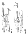
- the location of the pattern can be directly sensed with a sensor 40 mounted on the print head 30, as illustrated respectively as 40a, 40b in Figs. 2 and 2A .
- the print head 30 includes a nozzle or ink jet nozzle array 41 that is directed downward toward the upwardly facing surface 16 of a substrate such as the panel 15.
- the panel 15 may have, for example, depressions or channels 43 on its surface 16 that have been formed by stitching or molding, as illustrated in Fig. 2 .
- the sensor 40 measures the distance from the nozzle 41 to the surface 16. Information from the sensor 40 can be communicated to the controller 35 and correlated with the longitudinal and transverse position information of the print head 30 and interpreted to determine the location of the contoured pattern so that the printed image can be applied to the surface 16 in registration with the pre-applied contour pattern.
- the sensor 40 is a mechanical sensor 40a that includes a wheeled carriage 45.
- the nozzle 41 is mounted at the midpoint of the carriage 45, which is, in turn, pivotally connected to the print head 30 about a longitudinal axis 46 through the center of the carriage 45.
- the carriage 45 has left and right sensing wheels 47, 48, respectively, that ride on the surface 16 of the panel 15 and follow the contour.
- the carriage 45 moves vertically relative to the print head 30 and follows the contour of the surface 16.
- the nozzle 41 being midway between the wheels 47, 48, will be positioned vertically at the average of the vertical positions of the wheels 47, 48. In this way, the nozzle 41 is passively positioned at a controlled distance relative to the surface 16 of the panel 15 in response to the detected location of the surface 16 of the panel 15 as determined by the carriage 45 as the wheels 47, 48 ride on the surface 16.
- the distance between the UV head 23 and the fabric is preferably also controllable so that the curing light is always precisely focused onto the printed contoured surface of the fabric.
- This distance may be controlled by mounting the UV curing head to move with the print heads, such as by communicating the UV light through optic fibers adjacent the print heads, for example, one fiber on each side of the print heads, or by mounting the UV curing head 23 on a separate carriage and providing it with a separate distance adjusting servo motor.
- Separate control of the UV curing head 23 can be in response to the sensors used to measure print head distance or in response to separate sensors provided to measure curing head distance.
- a memory can be used to store a map of the surface or portion of the surface while a controller retrieves the correct distance information from the memory that corresponds to the position of the curing head over the fabric.
- the UV curing head can be fixed and the focal length of the UV light from the source automatically varied.
- Fig. 2A illustrates a rigid panel 15 having its outer upwardly facing surface 16 covered with a coarse woven or textured fabric.
- an optical or laser sensor 40b is provided either on the print head 30 or on the carriage at a fixed height from the plane of support of the fabric.
- the sensor 40b instantaneously measures the distance from the nozzle 41 to the surface 16 of the panel 15 and communicates the measurement to the controller 35.
- the nozzle 41 is mounted on an output actuator 51 of a servo motor 50 mounted in the print head 30.
- the controller 35 sends a control signal to the servo motor 50 to move the nozzle 41 on the print head 30 vertically in response to the distance measurement from the sensor 40b to maintain a constant distance from the nozzle 41 to the surface 16 of the panel 15.
- Printing on rigid panels can benefit from the sensing and adjustment of the distance from print nozzle to surface of the panel since the rigid frame of the panel and the thickness of the panel when supported on the frame of a printing apparatus makes the position of the upper surface of the panel unpredictable.
- Fig. 1 A illustrates an alternative embodiment 100 of the machine 10 described above.
- the machine embodiment 100 includes a stationary frame 111 with a longitudinal extent represented by an arrow 112 and a transverse extent represented by an arrow 113.
- the machine 100 has a front end 114 into which the rigid office partition panel 15 may be loaded onto a belt 121 of a conveyor system 120 having one or more flights which carry the panel 15 longitudinally through the machine 100.
- the belt 121 of the conveyor 120 extends across the width of the frame 111 and rests on a smooth stainless steel vacuum table 105, which has therein an array of upwardly facing vacuum holes 106 which communicate with the underside of the belt 121.
- the belt 121 is sufficiently porous that the vacuum from the table 105 communicates through the belt 121 to the underside of the rigid panel 15 to assist gravity in holding the panel 15. in place against the top side of the belt 121.
- the belt 121 has a high friction rubber-like surface 108 to help prevent a horizontal sliding of a panel resting on it, through which an array of holes 109 is provided to facilitate communication of the vacuum from the table 105 to the substrate.
- the top surface of the belt 121 of the conveyor 120 is such that it provides sufficient friction between it and the underside of the panel 15 to keep the panel 15 from sliding horizontally on the conveyor 120.
- the conveyor 120 is further sufficiently non-elastic so that it can be precisely advanced.
- the belt 121 has a non-elastic open weave backing 107 to provide dimensional stability to the belt while allowing the vacuum to be communicated between the holes 106 of the table 105 and the holes 109 in the surface of the belt 121.
- the forward motion of the panel 15 on the frame 111 is precisely controllable by indexing of the belt 121 by control of a servo drive motor 122 with signals from the controller 35.
- the belt 121 thereby retains the panels 15 in a precisely known longitudinal position on the belt 121 so as to carry the panels 15 through the longitudinal extent of the machine 100.
- Such indexing of the belt 121 should be controllable to an accuracy of about 0.0005 inches where used to move the panel 15 relative to a print head on a fixed bridge (which embodiment is not shown).
- the longitudinal movement of the belt 121 of the conveyor 120 is controlled by the conveyor drive 122 to move the panel into printing position and then to advance it downstream after it is printed.
- One or more additional separately controllable drives 132 may be provided to control the downstream flights, if any, of the conveyor 120.
- the printing station 125 includes a bridge 128. Where the belt 121 is operable to precisely index the panel 15 relative to the bridge 128, the bridge may be fixed to the frame 111 and extend transversely across it.
- a printhead carriage 129 is transversely moveable across the bridge 128 and has one or more sets 130 of ink jet printing heads thereon.
- the carriage 129 is preferably fixed to the armature of a linear servo motor 131 which has a linear array of stator magnets extending transversely across the bridge 128, so that the carriage 129 is transversely moveable across the bridge 128 by positioning and drive control signals sent to the servo 131 by the controller 35, described above.
- the bridge 128 is mounted to the moveable armatures 133a,134a that ride on longitudinal tracks 133b,134b of linear servo motors 133, 134 at each side of the conveyor 120.
- the bridge 128 is indexed in the longitudinal direction as transverse bands of an image are printed in successive scans of print heads 130, described below.
- This indexing should be as accurate as needed to insure that the scans register one with another and can be interlaced, as required, to produce the desired print quality and resolution. Such accuracy is preferred to be about 0.0005 inches. Lower resolution, and thus less accuracy, is acceptable for printing on textile surfaces than on smoother surfaces such as vinyl.
- Fig. 3 illustrates a set 130 of four ink jet printing heads 130a-130d configured to respectively apply the four colors of a CMYK color set.
- the ink jet printing heads 130a-d each include a linear array of one hundred twenty-eight (128) ink jet nozzles that extend in the longitudinal direction relative to the frame 111 and in a line perpendicular to the direction of travel of the carriage 129 on the bridge 128.
- the nozzles of each of the heads 130 are configured and controlled to simultaneously but selectively jet UV ink of one of the CMYK colors side by side across the substrate 15, and to do so in a series of cycles as the nozzles scan the substrate 15.
- the heads 130a-d of a set are arranged side-by-side to print consecutively across the same area of the substrate 15 as the carriage 129 moves across the bridge 128, each depositing one of the four colors sequentially on each dot position across the substrate 15.
- Each of the heads 130a-d is moveably mounted to the carriage to individually move vertically, or perpendicular to the plane of the substrate 15.
- the distance of each head 130a-d from the plane of the substrate 15 is controlled by a respective one of a set of servos 137a-d mounted to the carriage 129 to follow one behind the other over the same contour of the substrate 15.
- the servos 137a-d are responsive to signals from the controller 35 which controls the positions of the heads 130a-d to maintain each a controlled distance from the surface of the substrate 15 where the surface 16 of the substrate 15 is contoured.
- the heads Usually, it is desirable to maintain the heads a fixed distance from the surface 16 on which they are to print. This is achieved by providing optical sensors 138a,138b on the opposite transverse sides of the carriage 129.
- the printhead set 130 is bidirectional and prints whether moving to the right or to the left.
- the leading one of the sensors 138a or 138b measures the distance from the sensor 138 and the surface 16 of the substrate 15 at a point directly in line with, typically directly below, the sensor 138. This measurement is communicated to the controller 35, which records the measured distance and the coordinates on the surface 16 of the substrate 15 at which the measurement was taken.
- These coordinates need only include the transverse position on the substrate 15 where the information is to be used in the same pass or scan of the carriage in which the measurement was taken.
- the controller 35 may also record the longitudinal coordinate by taking into account the position of the panel 15 on the frame 111 relative to the bridge 128.
- the controller 35 controls the servos 137 to vertically position the each of the heads 130 to a predetermined distance from the contoured surface 16 of the substrate 15 as the respective head arrives at the transverse coordinate on the substrate 15 at which each measurement was taken.
- the nearest of the heads 130 to the leading sensor 138 which are spaced a distance B from the sensor 138, follows the contour of the fabric at a delay of V / B seconds after a given measurement was taken, where Vis the velocity of the carriage 129 on the bridge 128.
- the heads 130 are spaced apart a distance A and will each sequentially follow the same contour as the first head at VlA seconds after the preceding head.
- the extent of the heads 130 in the longitudinal direction determines the accuracy with which the heads can follow the contours of the substrate 15. Greater accuracy can be maintained, and more variable contours can be followed, by using narrower heads, for example, of 64 or 32 jets per head in the longitudinal direction. Accordingly, multiple sets of heads 130 can be arranged in a rectangular or other array on the carriage 129, with heads of the different sets being arranged side-by-side across the carriage 129 in the longitudinal direction of the substrate 15 and frame 111. For example, two sets of heads having 64 jets per head each or four sets of heads having 32 jets per head each will produce the same 128 dot wide scan, but with greater ability to maintain spacing from head to substrate where the contours vary in the longitudinal direction on the substrate 15.
- the UV curing station 124 is provided as illustrated in Fig. 1 A . It may include a printhead 23 transversely moveable independently of the print heads 130 across the downstream side of the bridge 128 or otherwise located downstream of the printing station 125, and/or may include UV light curing heads 123a and 123b mounted on the carriage 129. As the carriage 129 moves transversely on the bridge 128, only the curing head 123a,123b that trails the print heads 130 is operated so that the UV light exposes ink after its deposition onto the substrate 15.
- the curing heads 123a,123b may also be moveable toward and away from the plane of the substrate 15 and controllable by servos 139a,139b, respectively, to maintain their spacing from the surface 16, as illustrated in Fig. 3 .
- Proper curing of UV ink requires that the UV light be focused on the surface bearing the ink. Therefore, moving the UV heads 123a,123b to maintain a constant spacing from the surface 16 maintains the focus of the curing UV light.
- UV light curing heads are typically configured to sharply focus a narrow, longitudinally extending beam of UV light onto the printed surface.
- the focal lengths of the light curing heads 123a,123b may be varied to follow the contours of the substrate 15.
- the light curing head 123 where used, may similarly be configured to move perpendicular to the surface 16 of the substrate 15.
- the heat curing or drying station 126 may be fixed to the frame 111 downstream of the printing station 125 and the UV light curing station, if any, may be located off-line. Such a drying station 126 may be used to dry solvent based inks with heated air, radiation or other heating techniques. It may also be used to further cure or dry UV inks.
- Printing on rigid panels can benefit from the sensing and adjustment of the distance from print nozzle to surface of the panel since the rigid frame of the panel and the thickness of the panel when supported on the frame of a printing apparatus makes the position of the upper surface of the panel unpredictable.
Landscapes
- Health & Medical Sciences (AREA)
- General Health & Medical Sciences (AREA)
- Toxicology (AREA)
- Engineering & Computer Science (AREA)
- Manufacturing & Machinery (AREA)
- Ink Jet (AREA)
- Coloring (AREA)
Abstract
Description
- This application claims priority to
U.S. Patent Applications Serial No. 09/650,596, filed August 30, 2000 09/822,795, filed March 30, 2001 - The present invention relates to printing onto rigid substrates, and to the printing onto textured, contoured or other three-dimensional substrates. The invention is particularly related to the printing onto such substrates as those having textile fabric surfaces or molded objects, rigid panels such as office partitions, automobile interior panels and other contoured objects, and to such printing using ink jet printing techniques.
- Applying ink to a substrate by ink jet printing requires a proper spacing between the ink jet nozzles and the surface of the substrate to which the printing is applied. Normally, this spacing must be set to within one or two millimeters to maintain effective printing by an ink jet process. If the distance from the nozzles to the surface being printed is too great, deviations from ideal parallel paths of the drops from different nozzles become magnified. Further, the longer the flight path of the drops from the print head to the substrate,.the more dependent the accuracy of the printing becomes on the relative speed between the print head and the substrate. This dependency limits the rate of change in print head to substrate velocity, including changes in direction. Also, the velocity of the drops moving from the print head nozzles to the substrate declines with the distance traveled from the nozzles, and the paths of such drops become more greatly affected by air currents and other factors with increased nozzle to substrate distance. Additionally, droplet shape changes the farther the drop moves from the nozzle, which changes the effects of the drop on the substrate. Accordingly, variations in the distance from the print head to the substrate can cause irregular effects on the printed image.
- In addition to problems in jetting ink onto contoured surfaces, the curing of UV inks that requires sharply focused UV energy to deliver sufficient curing energy to the ink is difficult to achieve where the surface is contoured.
- Some substrates deform, even temporarily, when heated. Such deformation may be temporary, for example, where the material returns to its undetermed state when it cools. Nonetheless, even temporary deformation can adversely affect the print quality if it occurs when ink is being jetted onto the substrate. In spot curing of UV inks, which is performed by exposing ink to UV immediately upon its contacting the substrate, UV that is accompanied by heat producing radiation can deform substrates such as foam-board as the ink jets are making single or multiple passes over the print area.
- For the reasons stated above, ink jet printing has not been successful on contoured materials and other three-dimensional substrates, particularly printing with UV curable inks in ink jet printing processes.
- An objective of the present invention is to provide for the printing onto three-dimensional substrates, particularly onto highly textured fabrics, tufted or irregular fabrics and other materials, contoured surfaces such as quilts, and mattress covers, and onto molded, stamped and otherwise shaped rigid or semi-rigid materials, and other three-dimensional surfaces. A particular objective of the invention is to print onto such surfaces with ink jet or digital printing processes. One more particular objective of the invention is to print onto such substrates with UV curable inks.
- According to the principles of the present invention, printed images are applied to three-dimensional substrates with printing elements that are moveable relative to the plane of the substrate being printed. In certain embodiments, the invention provides a wide-substrate ink jet printing apparatus with print heads that move toward and away from the plane of a substrate to maintain a fixed distance between the nozzles of the printhead and the surface onto which the ink is being jetted. The variable distance over the plane of the substrate allows a controlled and uniform distance across which the ink is jetted.
- In one preferred embodiment of the invention, the printing element is an ink jet print head set having a plurality of heads, typically four, each for dispensing one of a set of colors onto the substrate to form a multi-colored image. To maintain the constant distance or to otherwise control the distance, one or more sensors is provided to measure the distance from the print head or from the print head carriage track to the point on the substrate on which ink is to be projected. The sensors generate reference signals that are fed to a controller that controls a servo motor on the print head carriage. The print head is moveably mounted to the carriage, for example on a ball screw mechanism, and is moveable toward and away from the plane of the substrate by operation of the servo motor.
- In a preferred embodiment of the invention, each print head of a set of four different color print heads is separately moveable relative to a common print head carriage, and is connected to one of a set of four servo motors by which its position relative to the plane of the substrate is capable of control relative to the positions of the other print heads. The print heads of the set are preferably arranged side by side in the transverse direction on the carriage so that one head follows the other across the width of the substrate as the carriage scans transversely across the substrate. Each head has a plurality of ink jet nozzles thereon for dispensing a given color of ink in a corresponding plurality of dots, for example 128 in number, that extend in a line transverse to the carriage, which is in a longitudinal direction perpendicular to the scan direction of the carriage. Two laser or optical sensors are provided on the carriage, one on each side of the heads, so that a distance measurement of the surface to the substrate can be taken ahead of the print heads when the heads are scanning in either direction. The controller records the contour of the substrate ahead of the print heads and varies the position of each print head, toward and away from the substrate plane, as each print head passes over the points at which the measurements were taken, so that each of the independently moveable heads follows the contour and maintains a fixed distance from the surface being printed.
- White it is preferred to adjust the position of the print head or nozzle thereof relative to the substrate which is fixed on a printing machine frame, the substrate surface can alternatively be positioned relative to a print head that is maintained at a fixed vertical position on the frame.
- Preferably, UV ink is printed onto material and the cure of the ink is initiated by exposure to UV light. UV curing lights may be mounted on the print head carriage, one on each side of the print head set, to expose the printed surface behind the heads. By so mounting the UV curing lights on the print head carriage, the jetted ink can be spot cured immediately upon contacting the substrate, which freezes the dots in position and prevents their spreading on or wicking into the substrate. With certain substrates, conventional or broad spectrum UV curing lights include radiation that can heat the substrate. In the case of foam-board and several other commonly used substrates, the light heats the substrate and deforms it. Usually, this deposition is temporary in that the substrate blisters or swells when heated only to return to its original condition upon cooling. Where the UV exposure is carried out downstream of the print head carriage, no harm results. But with spot curing, the substrate deforms at the point of printing, thereby adversely affecting the quality of the ink jet printing operation. This is prevented by using a "cold UV" source, or a source that includes a filter or other energy limiting device, for example, a limited bandwidth UV source, to prevent the energy from the source striking the substrate from carrying enough energy to heat the substrate. This may be done by providing sufficient UV energy at the relevant frequencies for curing the ink without heating the substrate. The invention is useful in printing onto substrates that can deform, even temporarily, when heated. Such deformation, even if temporary such that the material returns to its undeformed state when it cools, adversely affects the print quality with spot curing, which deforms the substrate as the ink jets are making single or multiple passes over the print area. This is particularly the case with printing onto form boards that make up the largest application of printing onto rigid substrates. Such deformation of the board from heat during printing would otherwise force adjustment of the head height above the deformation zone. The higher the head height the worse the print quality due to satellite and time of flight issues to name a few. With a cold UV system, the head to substrate distance can be minimized to maximize print quality.
- In prior practice, spot curing has not been used to ink jet print onto rigid substrates, except as proposed by us in our parent application. However, cold UV is known for curing UV ink downstream of a printing station, where it has been used to prevent permanent deformation or heat damage to the substrate. Temporary deformation that will disappear after the substrate cools "has not been a problem in the prior art. Such deformation would be a problem where slight raising or warping of the surface occurs as the ink is being jetted onto the substrate, which can occur during spot curing.
- With or following the exposure to the UV light, the printed textile substrates or other textured or porous fabric is subjected to heat, preferably by blowing heated air onto the material downstream of the printing station, which extends the UV light initiated curing process and removes uncured components of the ink. With quilted bedding fabric materials, UV curable ink is jetted onto the fabric and the jetted ink is exposed to UV curing light to cure the ink preferably to about 90 to 97% polymerization, with the fabric bearing the partially cured, jetted ink then heated in a hot air blower curing oven at which the UV light initiated polymerization continues, uncured monomers are vaporized, or both, in order to produce a printed image of UV ink that contains a low quantity of uncured monomer or other ink components, for example, less than 0.01%.
- Where UV ink is jetted onto a highly textured fabric such as a mattress cover ticking material, the ink is jetted at a dot density of from about 180x254 dots per inch per color to about 300x300 dots per inch per color. For certain common UV inks, four colors of a CMYK color palette are applied, each in drops or dots of, for example, about 75 picoliters, or approximately 80 nanograms, per drop, utilizing a UV ink jet print head. A UV curing light head is provided, which moves either with the print head or independent of the print head and exposes the deposited drops of UV ink with a beam of about 300 watts per linear inch, applying about 1 joule per square centimeter, thereby producing at least a 90% UV cure. The fabric on which the jetted ink has been thereby partially UV cured is then passed through an oven where it is heated to about 300°F for from about 30 seconds up to about three minutes. Forced hot air is preferably used to apply the heat in the oven, but other heating methods such as infrared or other radiant heaters may be used. Similar parameters may be used for cloth covered rigid panels such as office partitions.
- When printing onto contoured material, the distance from the print heads to the substrate where the ink is to be deposited can be determined by measuring the distance from a sensor to the substrate ahead of the print heads and mapping the location of the surface. For bidirectional print heads that move transversely across the longitudinally advancing fabric, providing two distance measuring sensors, one on each of the opposite sides of the print heads, are provided to measure the distance to the contoured fabric surface when the print heads are moving in either direction. For some inks and for sufficiently rigid materials, a mechanical rolling sensor may be used, for example, by providing a pair of rollers, with one roller ahead of, and one head behind, the print head so that the average distance between the two rollers and a reference point on the print head can be used to control the distance of the print head from the plane of the substrate. To achieve this, one or more print heads can be mounted to a carriage having the rollers on the ends thereof so that the mechanical link between the rollers moves the print head relative to the plane of the substrate. In most cases, a non-contact sensor, such as a laser or photo eye sensor, is preferred in lieu of each roller. The outputs of two sensors on opposite sides of the print heads can be communicated to a processor, to measure the distance from the heads to the fabric ahead of the bidirectional heads, to drive a servo motor connected to the print head to raise and lower the head relative to the substrate plane so that the print heads move parallel to the contoured surface and jet ink onto the fabric across a fixed distance.
- These and other objects of the present invention will be more readily apparent from the following detailed description of the preferred embodiments of the invention.
-
-
Fig. 1 is a perspective view of one embodiment of an apparatus embodying principles of the present invention in which ink jet printing is applied to panels of rigid office partitions that are covered with textured or contoured textile material or fabric. -
Fig. 1A is a perspective view, similar toFig. 1 , of another embodiment of an apparatus embodying principles of the present invention in which ink jet printing is applied to rigid panels. -
Fig. 2 is a cross-sectional view along line 2-2 ofFig. 1 showing structure for maintaining print head to substrate distance where a substrate is more highly contoured. -
Fig. 2A is a cross-sectional view similar toFig. 2 showing alternative structure for maintaining print head to substrate distance. -
Fig. 3 is a cross-sectional view along line 3-3 ofFig.1 A showing structure for maintaining print head to substrate distance on a contoured substrate. -
Fig. 1 illustrates a machine 10 for printing onto rigid panels. The machine 10 includes a stationary frame 11 with a longitudinal extent represented by anarrow 12 and a transverse extent represented by anarrow 13. The machine 10 has afront end 14 into which is advanced arigid panel 15, such as that of which an office partition may be formed. Thepanel 15 may include a metal orwooden frame 17 on which is stretched a facing material that forms thesurface 16 to be printed. Thesurface 16 may also be a flat but highly textured fabric, a molded material such as a foam or some other contoured or variable surface.Panels 15 are carried longitudinally on the machine 10 by a conveyor orconveyor system 20, formed of a pair of opposed pin tentering belt sets 21 which extend through the machine 10 and onto which thepanels 15 are fed at thefront end 14 of the machine 10. The belt sets 21 retain thepanels 15 in a precisely known longitudinal position on the belt sets 21 to carry thepanels 15 through the longitudinal extent of the machine 10, preferably with an accuracy of 1/4 inch. The longitudinal movement of thebelts 21 of theconveyor 20 is controlled by aconveyor drive 22. Theconveyor 20 may take alternative forms including, but not limited to, opposed cog-belt side securements, longitudinally moveable positive side clamps that engage thepanels 15 or other securing structure for holding thepanels 15 fixed relative to theconveyor 20. - Along the
conveyor 20 are provided three stations, including an ink jet printing station 25, a UVlight curing station 24, and a heated drying station 26. The printing station 25 includes an ink jet carriage having one or more ink jet printing heads 30 thereon. The carriage of the print heads 30 is shown as transversely moveable on the front of across bar 28 that extends transversely across the frame 11 and may, but not necessarily, also be longitudinally moveable on the frame 11 under the power of a transverseservo drive motor 31 and an optional longitudinal drive 32. Alternatively, theheads 30 may extend across the width of theweb 15 and be configured to print an entire transverse line of selectable points simultaneously onto thepanel 15. - The ink jet printing heads 30 are configured to jet UV ink, for example, at 75 picoliters, or approximately 80 nanograms, per drop, and may do so for each of four colors according to a CMYK color pallette. The dots are preferably dispensed at a resolution of about 180 dots per inch by about 254 dots per inch. The resolution may be higher or lower as desired, but the 180x254 resolution is preferred. If desirable for finer images or greater color saturation, 300x300 dots per inch is preferable. The drops of the different colors can be side-by-side or dot-on-dot. Dot-on-dot (sometimes referred to as drop-on-drop) produces higher density.
- The print heads 30 are provided with controls that allow for the selective operation of the
heads 30 to selectively print designs of one or more colors onto the surface of thepanel 15. Thedrive 22 for theconveyor 20, thedrives 31,32 for theprint head 30 and the operation of the print heads 30 are program controlled to printpatterns 33 at known locations on thepanel 15 by acontroller 35, which includes amemory 36 for storing programmed patterns, machine control programs and real time data regarding the nature and longitudinal and transverse location of printeddesigns 33 on thepanel 15 and the relative longitudinal position of thepanel 15 in the machine 10. - The
UV curing station 24 includes a UV light curing head 23 that may move with the print heads 30 or, as is illustrated, move independently of the print heads 30. The UV light curing head 23 is configured to sharply focus a narrow, longitudinally extending beam of UV light onto the printed surface of the fabric. The UV curing head 23 is provided with atransverse drive 19 which is controlled to transversely scan the printed surface of the fabric to move the light beam across the fabric. - Preferably, the curing head 23 is intelligently controlled by the
controller 35 to selectively operate and quickly move across areas having no printing and to scan only the printed images with UV light at a rate sufficiently slow to UV cure the ink, thereby avoiding wasting time and UV energy scanning unprinted areas. If the head 23 is included in the printing station 25 and is coupled to move with the print heads 30, UV curing light can be used in synchronism with the dispensing of the ink immediately following the dispensing of the ink. - The
UV curing station 24, in the illustrated embodiment, is preferably located either immediately downstream of the printing station 25, or on the print head carriage to the sides of the print heads, so that the fabric, immediately following printing, is subjected to a UV light cure. Such carriage mounting of the curing heads allows for the dots of ink to be frozen where they are deposited, avoiding drop spread and wicking of the ink. The UV curing heads, particularly when mounted on the carriage, are cold-UV light, which, through the use of filters or narrow bandwidth radiation, avoids heating a sensitive substrate such as foam-board and deforming it at the location where the ink drops are being deposited. Such cold-UV curing light systems use cold mirrors, infrared cut filters, and water cooled UV curing to keep the temperature of the substrate low. - In theory, one photon of UV light is required to cure one free radical of ink monomer so as to set the ink. In practice, one joule of UV light energy per square centimeter of printed surface area is supplied by the UV curing head 23. This is achieved by sweeping a UV beam across the printed area of the fabric at a power of 300 watts per linear inch of beam width. This is sufficient to produce a UV cure of at least 90%. Increasing the UV light power up to 600 watts per linear inch can be done to achieve a 97% or better cure. Alternatively, if fabric thickness and opacity are not too high, curing light can be projected from both sides of the fabric to enhance the curing of the UV ink. Using power much higher can result in the burning or even combustion of the fabric, so UV power has an upper practical limit.
- The heat curing or drying station 26 may be fixed to the frame 11 downstream of the UV light curing station or may be located off-line. With 97% UV cure, the ink will be sufficiently colorfast so as to permit the drying station to be off-line. When on-line, the drying station should extend sufficiently along the length of fabric to adequately cure the printed ink at the rate that the fabric is printed. When located off-line, the heat curing station can operate at a different rate than the rate of printing. Heat cure at the oven or drying station 26 maintains the ink on the fabric at about 300°F for up to three minutes. Heating of from 30 seconds to three minutes is the anticipated advantageous range. Heating by forced hot air is preferred, although other heat sources, such as infrared heaters, can be used as long as they adequately penetrate the fabric to the depth of the ink.
- A quilting station may be located on-line with the printing station or off-line, and either before or after the printing station. Locating a quilting station downstream of the oven 26 is advantageous in the case of quilted comforters and mattress covers and where quilting is to be applied and registered with printing on the fabric. A single-needle quilting station may be used, such as is described in
U.S. Patent No. 5,832,849, to Kaetterhenry et al . entitled "Web-fed Chain-stitch Single-needle Mattress Cover Quilter with Needle Deflection Compensation", which is expressly incorporated by reference herein. Other suitable single-needle type quilting machines with which the present invention may be used are disclosed inU.S. Patent Nos. 5,640,916 and5,685,250 , respectively, both entitled "Quilting Method and Apparatus", expressly incorporated by reference herein. Such a quilting station may also include a multi-needle quilting structure such as that disclosed inU.S. Patent No. 5,154,130 , also expressly incorporated by reference herein. - Where quilting, molding or other contouring of a substrate is carried out before the printing onto the substrate, registration of the printing to the pre-applied contouring will usually be desired. To register the printing to pre-applied contours, the location of the contour pattern can be calculated in relation to a reference point on the substrate that can be sensed by sensors at the printing station. The location of the pattern can be directly sensed with a sensor 40 mounted on the
print head 30, as illustrated respectively as 40a, 40b inFigs. 2 and 2A . Theprint head 30 includes a nozzle or inkjet nozzle array 41 that is directed downward toward the upwardly facingsurface 16 of a substrate such as thepanel 15. Thepanel 15 may have, for example, depressions orchannels 43 on itssurface 16 that have been formed by stitching or molding, as illustrated inFig. 2 . The sensor 40 measures the distance from thenozzle 41 to thesurface 16. Information from the sensor 40 can be communicated to thecontroller 35 and correlated with the longitudinal and transverse position information of theprint head 30 and interpreted to determine the location of the contoured pattern so that the printed image can be applied to thesurface 16 in registration with the pre-applied contour pattern. - In the embodiment of
Fig. 2 , the sensor 40 is a mechanical sensor 40a that includes awheeled carriage 45. Thenozzle 41 is mounted at the midpoint of thecarriage 45, which is, in turn, pivotally connected to theprint head 30 about alongitudinal axis 46 through the center of thecarriage 45. Thecarriage 45 has left andright sensing wheels surface 16 of thepanel 15 and follow the contour. Thecarriage 45 moves vertically relative to theprint head 30 and follows the contour of thesurface 16. Thenozzle 41, being midway between thewheels wheels nozzle 41 is passively positioned at a controlled distance relative to thesurface 16 of thepanel 15 in response to the detected location of thesurface 16 of thepanel 15 as determined by thecarriage 45 as thewheels surface 16. - The distance between the UV head 23 and the fabric is preferably also controllable so that the curing light is always precisely focused onto the printed contoured surface of the fabric. This distance may controlled by mounting the UV curing head to move with the print heads, such as by communicating the UV light through optic fibers adjacent the print heads, for example, one fiber on each side of the print heads, or by mounting the UV curing head 23 on a separate carriage and providing it with a separate distance adjusting servo motor. Separate control of the UV curing head 23 can be in response to the sensors used to measure print head distance or in response to separate sensors provided to measure curing head distance. Where the print head sensors are used to control curing head to fabric distance, a memory can be used to store a map of the surface or portion of the surface while a controller retrieves the correct distance information from the memory that corresponds to the position of the curing head over the fabric. Alternatively, the UV curing head can be fixed and the focal length of the UV light from the source automatically varied.
- Whether the
panel 15 has a contoured pattern on itssurface 16 or merely a textured material, print quality is maintained by maintaining precise spacing between the nozzle 44 and thesurface 16 of thepanel 15.Fig. 2A illustrates arigid panel 15 having its outer upwardly facingsurface 16 covered with a coarse woven or textured fabric. As theprint head 30 moves transversely on thecross bar 28, the vertical position, relative to theprint head 30, of the point on thesurface 16 of thepanel 15 at which thenozzle 41 is directed varies, often one or more millimeters. To measure such distance variations, an optical or laser sensor 40b is provided either on theprint head 30 or on the carriage at a fixed height from the plane of support of the fabric. The sensor 40b instantaneously measures the distance from thenozzle 41 to thesurface 16 of thepanel 15 and communicates the measurement to thecontroller 35. Thenozzle 41 is mounted on anoutput actuator 51 of aservo motor 50 mounted in theprint head 30. Thecontroller 35 sends a control signal to theservo motor 50 to move thenozzle 41 on theprint head 30 vertically in response to the distance measurement from the sensor 40b to maintain a constant distance from thenozzle 41 to thesurface 16 of thepanel 15. - Printing on rigid panels, even where the surface is not textured or contoured, can benefit from the sensing and adjustment of the distance from print nozzle to surface of the panel since the rigid frame of the panel and the thickness of the panel when supported on the frame of a printing apparatus makes the position of the upper surface of the panel unpredictable.
-
Fig. 1 A illustrates analternative embodiment 100 of the machine 10 described above. Themachine embodiment 100 includes astationary frame 111 with a longitudinal extent represented by anarrow 112 and a transverse extent represented by anarrow 113. Themachine 100 has afront end 114 into which the rigidoffice partition panel 15 may be loaded onto abelt 121 of aconveyor system 120 having one or more flights which carry thepanel 15 longitudinally through themachine 100. Thebelt 121 of theconveyor 120 extends across the width of theframe 111 and rests on a smooth stainless steel vacuum table 105, which has therein an array of upwardly facing vacuum holes 106 which communicate with the underside of thebelt 121. Thebelt 121 is sufficiently porous that the vacuum from the table 105 communicates through thebelt 121 to the underside of therigid panel 15 to assist gravity in holding thepanel 15. in place against the top side of thebelt 121. Preferably, thebelt 121 has a high friction rubber-like surface 108 to help prevent a horizontal sliding of a panel resting on it, through which an array ofholes 109 is provided to facilitate communication of the vacuum from the table 105 to the substrate. - The top surface of the
belt 121 of theconveyor 120 is such that it provides sufficient friction between it and the underside of thepanel 15 to keep thepanel 15 from sliding horizontally on theconveyor 120. Theconveyor 120 is further sufficiently non-elastic so that it can be precisely advanced. To this end, thebelt 121 has a non-elastic open weave backing 107 to provide dimensional stability to the belt while allowing the vacuum to be communicated between theholes 106 of the table 105 and theholes 109 in the surface of thebelt 121. The forward motion of thepanel 15 on theframe 111 is precisely controllable by indexing of thebelt 121 by control of aservo drive motor 122 with signals from thecontroller 35. Thebelt 121 thereby retains thepanels 15 in a precisely known longitudinal position on thebelt 121 so as to carry thepanels 15 through the longitudinal extent of themachine 100. Such indexing of thebelt 121 should be controllable to an accuracy of about 0.0005 inches where used to move thepanel 15 relative to a print head on a fixed bridge (which embodiment is not shown). - In the
embodiment 100 illustrated inFig. 1A , the longitudinal movement of thebelt 121 of theconveyor 120 is controlled by theconveyor drive 122 to move the panel into printing position and then to advance it downstream after it is printed. One or more additional separatelycontrollable drives 132 may be provided to control the downstream flights, if any, of theconveyor 120. - Along the length of travel of the
conveyor 120 are provided three stations, including an inkjet printing station 125 and one or more curing or drying stations, which may include UV light curing stations 124 and/or aheating station 126. Theprinting station 125 includes abridge 128. Where thebelt 121 is operable to precisely index thepanel 15 relative to thebridge 128, the bridge may be fixed to theframe 111 and extend transversely across it. Aprinthead carriage 129 is transversely moveable across thebridge 128 and has one ormore sets 130 of ink jet printing heads thereon. Thecarriage 129 is preferably fixed to the armature of alinear servo motor 131 which has a linear array of stator magnets extending transversely across thebridge 128, so that thecarriage 129 is transversely moveable across thebridge 128 by positioning and drive control signals sent to theservo 131 by thecontroller 35, described above. - In the illustrated embodiment, the
bridge 128 is mounted to themoveable armatures 133a,134a that ride onlongitudinal tracks 133b,134b oflinear servo motors conveyor 120. Once apanel 15 is positioned under thebridge 128 by movement of thebelt 121, thebridge 128 is indexed in the longitudinal direction as transverse bands of an image are printed in successive scans of print heads 130, described below. This indexing should be as accurate as needed to insure that the scans register one with another and can be interlaced, as required, to produce the desired print quality and resolution. Such accuracy is preferred to be about 0.0005 inches. Lower resolution, and thus less accuracy, is acceptable for printing on textile surfaces than on smoother surfaces such as vinyl. -
Fig. 3 illustrates aset 130 of four inkjet printing heads 130a-130d configured to respectively apply the four colors of a CMYK color set. The ink jet printing heads 130a-d each include a linear array of one hundred twenty-eight (128) ink jet nozzles that extend in the longitudinal direction relative to theframe 111 and in a line perpendicular to the direction of travel of thecarriage 129 on thebridge 128. The nozzles of each of theheads 130 are configured and controlled to simultaneously but selectively jet UV ink of one of the CMYK colors side by side across thesubstrate 15, and to do so in a series of cycles as the nozzles scan thesubstrate 15. Theheads 130a-d of a set are arranged side-by-side to print consecutively across the same area of thesubstrate 15 as thecarriage 129 moves across thebridge 128, each depositing one of the four colors sequentially on each dot position across thesubstrate 15. - Each of the
heads 130a-d is moveably mounted to the carriage to individually move vertically, or perpendicular to the plane of thesubstrate 15. The distance of eachhead 130a-d from the plane of thesubstrate 15 is controlled by a respective one of a set ofservos 137a-d mounted to thecarriage 129 to follow one behind the other over the same contour of thesubstrate 15. Theservos 137a-d are responsive to signals from thecontroller 35 which controls the positions of theheads 130a-d to maintain each a controlled distance from the surface of thesubstrate 15 where thesurface 16 of thesubstrate 15 is contoured. - Usually, it is desirable to maintain the heads a fixed distance from the
surface 16 on which they are to print. This is achieved by providingoptical sensors 138a,138b on the opposite transverse sides of thecarriage 129. The printhead set 130 is bidirectional and prints whether moving to the right or to the left. As theprint head carriage 129 moves on thebridge 128, the leading one of thesensors 138a or 138b measures the distance from the sensor 138 and thesurface 16 of thesubstrate 15 at a point directly in line with, typically directly below, the sensor 138. This measurement is communicated to thecontroller 35, which records the measured distance and the coordinates on thesurface 16 of thesubstrate 15 at which the measurement was taken. These coordinates need only include the transverse position on thesubstrate 15 where the information is to be used in the same pass or scan of the carriage in which the measurement was taken. However, thecontroller 35 may also record the longitudinal coordinate by taking into account the position of thepanel 15 on theframe 111 relative to thebridge 128. - In response to the measurements, the
controller 35 controls the servos 137 to vertically position the each of theheads 130 to a predetermined distance from the contouredsurface 16 of thesubstrate 15 as the respective head arrives at the transverse coordinate on thesubstrate 15 at which each measurement was taken. As a result, the nearest of theheads 130 to the leading sensor 138, which are spaced a distance B from the sensor 138, follows the contour of the fabric at a delay of V/B seconds after a given measurement was taken, where Vis the velocity of thecarriage 129 on thebridge 128. Similarly, theheads 130 are spaced apart a distance A and will each sequentially follow the same contour as the first head at VlA seconds after the preceding head. - The extent of the
heads 130 in the longitudinal direction determines the accuracy with which the heads can follow the contours of thesubstrate 15. Greater accuracy can be maintained, and more variable contours can be followed, by using narrower heads, for example, of 64 or 32 jets per head in the longitudinal direction. Accordingly, multiple sets ofheads 130 can be arranged in a rectangular or other array on thecarriage 129, with heads of the different sets being arranged side-by-side across thecarriage 129 in the longitudinal direction of thesubstrate 15 andframe 111. For example, two sets of heads having 64 jets per head each or four sets of heads having 32 jets per head each will produce the same 128 dot wide scan, but with greater ability to maintain spacing from head to substrate where the contours vary in the longitudinal direction on thesubstrate 15. - Where UV curable ink is used, the UV curing station 124 is provided as illustrated in
Fig. 1 A. It may include a printhead 23 transversely moveable independently of the print heads 130 across the downstream side of thebridge 128 or otherwise located downstream of theprinting station 125, and/or may include UV light curing heads 123a and 123b mounted on thecarriage 129. As thecarriage 129 moves transversely on thebridge 128, only the curinghead substrate 15. The curing heads 123a,123b may also be moveable toward and away from the plane of thesubstrate 15 and controllable byservos surface 16, as illustrated inFig. 3 . Proper curing of UV ink requires that the UV light be focused on the surface bearing the ink. Therefore, moving the UV heads 123a,123b to maintain a constant spacing from thesurface 16 maintains the focus of the curing UV light. UV light curing heads are typically configured to sharply focus a narrow, longitudinally extending beam of UV light onto the printed surface. Therefore, instead of physically moving the UV light curing heads orsources substrate 15. The light curing head 123, where used, may similarly be configured to move perpendicular to thesurface 16 of thesubstrate 15. - The heat curing or drying
station 126 may be fixed to theframe 111 downstream of theprinting station 125 and the UV light curing station, if any, may be located off-line. Such a dryingstation 126 may be used to dry solvent based inks with heated air, radiation or other heating techniques. It may also be used to further cure or dry UV inks. - Printing on rigid panels, even where the surface is not textured or contoured, can benefit from the sensing and adjustment of the distance from print nozzle to surface of the panel since the rigid frame of the panel and the thickness of the panel when supported on the frame of a printing apparatus makes the position of the upper surface of the panel unpredictable.
- The above description is representative of certain preferred embodiments of the invention. Those skilled in the art will appreciate that various changes and additions may be made to the embodiments described above without departing from the principles of the present invention.
Claims (22)
- A method of dispensing UV curable ink from a printhead onto a substantially rigid substrate formed of a material that has a tendency to deform at least temporarily if exposed to radiant energy, the method comprising:moving a printhead approximately parallel to a substrate at a printing station;dispensing ink from the printhead onto a surface of the substrate; andproviding at least one cold UV curing assembly moveable with the printhead and configured to direct UV radiation onto the surface of the substrate to freeze the dispensed ink on the surface and to substantially cure the ink without impinging radiation that would materially deform the substrate while the substrate is at the printing station.
- A method of ink jet printing UV curable ink from an ink jet printhead onto a rigid substrate formed of a material that has a tendency to at least temporarily deform in the direction of printhead if exposed to radiant curing energy while at a printing station, the method comprising:moving a printhead carriage having an ink jet printhead thereon approximately parallel to a substrate at a printing station;jetting ink from the head onto the surface of a substrate;providing at least one cold UV curing assembly on the carriage, adjacent to and moveable with the printhead, and oriented to direct UV energy onto the surface of the substrate at the printing station sufficiently close to where ink is being jetted onto the surface to freeze dots of the jetted ink on the surface; andthe cold UV assembly being effective to impinge sufficient UV light on the ink to substantially cure the ink without impinging radiation that would heat the substrate so as to deform it, even temporarily, while at the printing station.
- The method of claim 1 or claim 2 further comprising adjusting the distance from the printhead to the substrate to position the head at a predetermined distance from the surface of the substrate on which ink is jetted from the head.
- The method of any preceding claim further comprising adjusting the distance of the UV light from a light source to focus the UV light onto the surface that bears the jetted ink.
- The method of any preceding claim further comprising adjusting the focal length from a source of the UV light on the surface that bears the jetted ink to maintain the focus of UV light thereon as distance from the source to the surface varies.
- The method of any preceding claim further comprising at least partially curing the ink jetted onto the surface by exposing the jetted ink to ultraviolet light and then heating the surface having the at least partially cured ink thereon to reduce the content of unpolymerized monomers of the ink on the substrate.
- The method of claim 6 wherein the heating includes flowing heated air onto the surface of the substrate having the at least partially cured UV light cured ink thereon to remove uncured components of the ink from the substrate.
- The method of any preceding claim further comprising:sensing the position of the surface of the substrate relative to the carriage; andadjusting the distance from the printhead to the plane of the substrate in response to said sensing.
- The method of claim 8 wherein:the sensing of the positions is carried out while moving the printhead carriage; andthe adjusting includes varying the position of the printhead relative to the plane of the substrate as the printhead carriage moves so as to maintain the predetermined distance the printhead from the surface of the substrate in response to the sensed position.
- The method of any preceding claim wherein the providing of at least one cold UV curing assembly on the carriage includes providing at least two cold UV curing heads, adjacent to the printhead, one on each side thereof, and moveable therewith, and oriented to direct UV energy onto the surface of the substrate at the printing station sufficiently close to where ink is being jetted onto the surface to freeze dots of the jetted ink on the surface; the cold UV curing heads being energizable alternately to direct UV energy onto the surface of the substrate on the trailing side of the carriage.
- An apparatus for printing on surfaces of substrates with UV curable ink from an ink jet printhead onto a rigid substrate formed of a material that has a tendency to at least temporarily deform in the direction of printhead if exposed to radiant curing energy while at a printing station comprising:a substrate support defining a substrate supporting plane at a printing station;a printhead track extending parallel to the plane having a printhead carriage moveable thereon;at least one ink jet printhead on the carriage;at least one cold UV curing assembly moveable with the printhead and configured to direct UV radiation onto the surface of the substrate to freeze the dispensed ink on the surface and to substantially cure the ink without impinging radiation that would materially deform the substrate while the substrate is at the printing station.
- An apparatus for printing on surfaces of substrates with UV curable ink from an ink jet printhead onto a rigid substrate formed of a material that has a tendency to at least temporarily deform in the direction of printhead if exposed to radiant curing energy while at a printing station comprising:a substrate support defining a substrate supporting plane at a printing station; a printhead track extending parallel to the plane having a printhead carriage moveable thereon;at least one ink jet printhead on the carriage;at least one UV curing head on the carriage, adjacent to and moveable with the printhead, and sufficiently close to the ink jet printhead to freeze dots of ink in position on the substrate when jetted thereon from the printhead; andthe UV curing head being configured to emit sufficient UV energy to substantially cure the ink jetted onto the substrate without heating and thermally deforming, even temporarily while at the printing station, a substrate formed of such a material, so that the surface of the material being printed upon does not move from the plane for printing.
- The apparatus of claim 11 or claim 12 further comprising:a plurality of ink jet printheads each moveably supported on the carriage and directed toward the surface of a substrate when supported by the substrate support;a sensor operable to determine a location on the surface of the substrate; andthe printheads being separately and selectively moveable perpendicular to the plane in response to the sensor to a predetermined distance from the determined location on the surface of the substrate; anda controller operable to move and control the printheads to print on the substrate by jetting ink from the printheads across the predetermined distance and onto the surface of a substrate.
- The apparatus of claim 13 wherein:the at least one UV curing head includes at least two cold UV curing heads, one positioned on the carriage at each side of the printheads so that one leads the printheads and one trails the printheads as the carriage moves on in either of two opposite directions on the track; andthe controller is operable to activate at least the trailing one of the UV curing heads to expose the ink jetted by the printheads on the surface of the substrate in the same pass of the carriage over the surface in which the ink being exposed was jetted.
- The apparatus of claim 14 wherein:the UV curing head is moveable relative to the plane; andthe controller is operable to move the curing head to maintain focus of UV light from the curing head on ink jetted onto the surface of the substrate.
- The apparatus of any one of claims 11 to 15 further comprising a heating station positioned so as to heat UV light exposed ink on a substrate.
- The apparatus of claim 16 wherein the heating station includes a blower oriented to direct heated air onto a substrate on the support.
- The apparatus of any one of claims 11 to 17 wherein:the ink jet printhead includes a plurality of individually moveable printheads spaced in the direction of movement of the carriage so as to sequentially pass over the same areas of the substrate, each printing one of a set of colors thereon;the printheads being separately and selectively moveable perpendicular to the plane in response to the sensor to maintain a constant distance of travel of ink from each printhead to the surface of the substrate; anda controller operable to control the printheads to sequentially follow the contour of the substrate surface as the carriage moves across the substrate.
- The apparatus of claim 18 wherein the plurality of ink jet printheads includes a plurality of sets of individually moveable printheads arranged side-by-side on the carriage perpendicular to the direction of movement of the carriage so that each can maintain a controlled spacing from the substrate where the contour of the substrate varies in the direction perpendicular to the movement of the carriage.
- The apparatus of any one of claims 11 to 19 wherein the ink jet printhead includes a plurality of individually moveable printheads arranged side-by-side on the carriage perpendicular to the direction of movement of the carriage so that each can maintain a controlled spacing from the substrate where the contour of the substrate varies in the direction perpendicular to the movement of the carriage.
- The apparatus of any one of claims 11 to 20 wherein:the at least one UV curing head on the carriage includes at least two UV curing heads on the carriage, one on each side of the printhead, sufficiently close to the ink jet printhead to freeze dots of ink in position on the substrate when jetted thereon from the printhead; andthe apparatus further comprising a controller operative to control the printhead to print in a bidirectional scanning motion on the substrate, and to activate the UV curing heads alternately to expose jetted ink on the trailing side of the printhead.
- An apparatus for printing on substrates having a tendency to deform when exposed to energy from a curing head comprising:a substrate support to support a substrate for printing thereon;a printhead track extending transversely of the support having a printhead carriage moveable thereon;a drive operative to impart longitudinal movement between a substrate on the support and the track;a carriage motor operative to move the carriage in a scanning motion transversely on the track;at least one ink jet printhead on the carriage;a controller operative to control the drive, the carriage motor and the printhead, to selectively jet UV curable ink onto a substrate on the support from the printhead with the carriage moving bidirectionally in successive transverse rows as the track incrementally moves longitudinally relative to the substrate;a pair of cold-UV curing heads on the carriage, one on each side of the printhead sufficiently close to the printhead to freeze dots of ink in position on the substrate upon having been jetted thereon from the printhead while imparting sufficiently low thermal energy to the substrate in the vicinity of the printhead to avoid even temporary deformation of the substrate where ink is being jetted thereon; andthe controller being operative to control the curing heads to activate the curing head on the trailing side of the printhead and deactivate the curing head on a leading side of the printhead as the printhead is printing.
Applications Claiming Priority (3)
| Application Number | Priority Date | Filing Date | Title |
|---|---|---|---|
| US65059600A | 2000-08-30 | 2000-08-30 | |
| US09/822,795 US6523921B2 (en) | 2000-08-30 | 2001-03-30 | Method and apparatus for printing on rigid panels and other contoured or textured surfaces |
| EP01968282A EP1313619B1 (en) | 2000-08-30 | 2001-08-30 | Method and apparatus for printing on rigid panels and contoured or textured surfaces |
Related Parent Applications (1)
| Application Number | Title | Priority Date | Filing Date |
|---|---|---|---|
| EP01968282A Division EP1313619B1 (en) | 2000-08-30 | 2001-08-30 | Method and apparatus for printing on rigid panels and contoured or textured surfaces |
Publications (1)
| Publication Number | Publication Date |
|---|---|
| EP1955861A1 true EP1955861A1 (en) | 2008-08-13 |
Family
ID=24609535
Family Applications (1)
| Application Number | Title | Priority Date | Filing Date |
|---|---|---|---|
| EP08075214A Withdrawn EP1955861A1 (en) | 2000-08-30 | 2001-08-30 | Method and apparatus for printing on rigid panels and countoured or textured surfaces |
Country Status (3)
| Country | Link |
|---|---|
| US (1) | US6523921B2 (en) |
| EP (1) | EP1955861A1 (en) |
| CN (1) | CN101219611A (en) |
Cited By (2)
| Publication number | Priority date | Publication date | Assignee | Title |
|---|---|---|---|---|
| DE102013216770A1 (en) * | 2013-08-23 | 2015-02-26 | Bundesdruckerei Gmbh | Printing device and method for applying a pressure medium |
| EP4173835A1 (en) * | 2021-10-29 | 2023-05-03 | Shenzhen Anycubic Technology Co., Ltd. | Printing device |
Families Citing this family (116)
| Publication number | Priority date | Publication date | Assignee | Title |
|---|---|---|---|---|
| US20040239705A1 (en) * | 2001-10-05 | 2004-12-02 | Reiji Arikita | Ink jet printing apparatus and printing method using ink jet |
| DE60335613D1 (en) | 2002-04-03 | 2011-02-17 | Masonite Corp | METHOD AND DEVICE FOR PRODUCING AN IMAGE ON A SUBJECT AND AN OBJECT MANUFACTURED BY THE PROCESS |
| CN100361815C (en) * | 2002-04-24 | 2008-01-16 | 东芝泰格有限公司 | Ink jet recording apparatus |
| JP4382364B2 (en) * | 2002-04-24 | 2009-12-09 | 株式会社東芝 | Liquid ink |
| AU2003279701A1 (en) * | 2002-07-01 | 2004-01-19 | Inca Digital Printers Limited | Printing with ink |
| US7390362B2 (en) * | 2002-10-15 | 2008-06-24 | Microboards Llc | Thermal printer |
| ITMO20020369A1 (en) * | 2002-12-30 | 2004-06-30 | Tecno Europa Srl | SYSTEM FOR PRINTING OBJECTS. |
| US20090261004A1 (en) * | 2003-01-14 | 2009-10-22 | Picbags, L.P. | Combination System And Golf Bag |
| US20040175218A1 (en) * | 2003-03-05 | 2004-09-09 | Katzer Lawrence John | Method and apparatus for printing on flat and non-flat objects |
| US20040196318A1 (en) * | 2003-04-01 | 2004-10-07 | Su Massharudin Bin | Method of depositing phosphor on light emitting diode |
| JP2004306191A (en) * | 2003-04-07 | 2004-11-04 | Seiko Epson Corp | Table device, film forming device, optical element, semiconductor element, and electronic equipment |
| FR2859129B1 (en) * | 2003-08-28 | 2005-11-11 | Sydel | SYSTEM FOR CONTINUOUSLY ADJUSTING THE DISTANCE BETWEEN A MARKING HEAD AND A MOBILE OBJECT AND MARKING DEVICE COMPRISING SUCH A SYSTEM |
| KR101322166B1 (en) * | 2004-01-30 | 2013-10-25 | 폴리타입 에스. 에이. | High precision feed particularly useful for UV ink jet printing on vinyl |
| TWI225828B (en) * | 2004-02-17 | 2005-01-01 | Benq Corp | Printing system and related calibration methods |
| GB0408182D0 (en) * | 2004-04-13 | 2004-05-19 | Khodabandehloo Koorosh | Marking meat products with a machine-readable visual code |
| KR100560082B1 (en) * | 2004-04-27 | 2006-03-13 | 한국과학기술원 | 3D solid color coloring method and device |
| JP2005324130A (en) * | 2004-05-14 | 2005-11-24 | Seiko Epson Corp | Droplet discharge device, electro-optical device, method of manufacturing electro-optical device, and electronic apparatus |
| US7350890B2 (en) * | 2004-08-26 | 2008-04-01 | The Boeing Company | Apparatus and methods for applying images to a surface |
| CN101111386B (en) * | 2004-12-03 | 2010-06-16 | 富士胶卷迪马蒂克斯股份有限公司 | Print apparatus |
| US7661810B2 (en) * | 2005-03-02 | 2010-02-16 | Fujifilm Corporation | Image recording apparatus and inkjet apparatus for double-side recording |
| US8493628B2 (en) * | 2005-04-21 | 2013-07-23 | The Boeing Company | Reproduction of images onto surfaces |
| US20060238815A1 (en) * | 2005-04-21 | 2006-10-26 | The Boeing Company | Systems and methods of reproducing images onto surfaces |
| FR2890597A1 (en) * | 2005-09-13 | 2007-03-16 | Ardeje Sarl | Digital inkjet printer has an automatically adjusting elevating table with a support plate on which different media can be placed so that the printer can readily be used with said different media |
| US7445302B2 (en) * | 2005-09-21 | 2008-11-04 | Lexmark International, Inc | Method for determining a printhead gap in an ink jet apparatus that performs bi-directional alignment of the printhead |
| US20070095218A1 (en) * | 2005-10-31 | 2007-05-03 | Thomas & Betts International, Inc. | Pole marking system for improved manufacturing process |
| JP2007156092A (en) * | 2005-12-05 | 2007-06-21 | Sharp Corp | Image forming apparatus and method for adjusting image forming apparatus |
| DE102006003056B4 (en) * | 2006-01-20 | 2014-05-08 | Phoenix Contact Gmbh & Co. Kg | Ink printer for printing on objects |
| US7735439B1 (en) | 2006-02-22 | 2010-06-15 | Atlanta Attachment Company | Panel quilting machine |
| EP1884365A1 (en) * | 2006-07-28 | 2008-02-06 | Abb Research Ltd. | Paint applicator and coating method |
| US8733274B2 (en) * | 2006-10-20 | 2014-05-27 | Hewlett-Packard Development Company, L.P. | Tube mounted inkjet printhead die |
| DE102007036374A1 (en) * | 2007-07-31 | 2009-02-05 | Phoenix Contact Gmbh & Co. Kg | Marking object and marking device |
| US9422095B2 (en) | 2007-07-31 | 2016-08-23 | Phoenix Contact Gmbh & Co. Kg | Marking object |
| US20090181217A1 (en) * | 2008-01-11 | 2009-07-16 | Swc Graphics, Inc. | Ink jet printing on sport court and other polymer tiles |
| US8979257B2 (en) * | 2008-02-14 | 2015-03-17 | Hewlett-Packard Development Company, L.P. | Printing or coating apparatus and method |
| JP5280073B2 (en) * | 2008-03-13 | 2013-09-04 | 株式会社ミマキエンジニアリング | Printing system, inkjet printer, and printing method |
| US7922272B2 (en) * | 2008-04-11 | 2011-04-12 | The Boeing Company | Method for application and accurate positioning of graphics on a surface |
| US9040124B2 (en) * | 2008-05-29 | 2015-05-26 | Illinois Tool Works Inc. | Dual cure method for ink for increased durability and adhesion to golf balls |
| DE102008034743A1 (en) * | 2008-07-24 | 2010-01-28 | Khs Ag | Device for printing on containers |
| US7962237B2 (en) * | 2008-08-06 | 2011-06-14 | Objet Geometries Ltd. | Method and apparatus for optimizing a scanning plan in three-dimensional printing |
| US9272558B2 (en) * | 2009-02-27 | 2016-03-01 | Frenchporte, Llc | Door manufacturing system and method |
| US8724131B2 (en) * | 2009-03-04 | 2014-05-13 | Canon Kabushiki Kaisha | Method, apparatus and computer-readable storage medium for use in inkjet printing |
| JP2012527387A (en) * | 2009-05-21 | 2012-11-08 | インクス インターナショナル インク カンパニー | Apparatus and associated method for printing on an object having a generally cylindrical shape |
| US8205984B2 (en) * | 2009-09-29 | 2012-06-26 | Hewlett-Packard Development Company, L.P. | Web printer and support structure |
| US8739716B2 (en) * | 2010-02-23 | 2014-06-03 | Atlanta Attachment Company | Automated quilting and tufting system |
| US20110243632A1 (en) * | 2010-03-31 | 2011-10-06 | Ncr Corporation | Media position sensing |
| JP5825762B2 (en) * | 2010-05-13 | 2015-12-02 | キヤノン株式会社 | Printing apparatus and printing apparatus control method |
| JP4999962B2 (en) * | 2010-05-13 | 2012-08-15 | キヤノン株式会社 | Printing apparatus and printing method |
| US9061521B2 (en) | 2010-09-22 | 2015-06-23 | 3Dphotoworks Llc | Method and apparatus for three-dimensional digital printing |
| BE1019567A3 (en) * | 2010-11-05 | 2012-08-07 | Mutoh Belgium Nv | DEVICE FOR AFTER TREATMENT OF MEDIA PRINTED WITH INK-JET. |
| EP2682268B1 (en) * | 2011-03-04 | 2017-02-15 | Mimaki Engineering Co., Ltd. | Inkjet recording device |
| EP2551123B1 (en) * | 2011-07-26 | 2016-08-17 | Seiko Epson Corporation | Printing method, printed material and molded article |
| JP5936836B2 (en) * | 2011-09-09 | 2016-06-22 | 株式会社ミマキエンジニアリング | Droplet discharge device |
| CN102529425A (en) * | 2011-11-18 | 2012-07-04 | 南京德众数码科技有限公司 | Continuous type platform printing device |
| US20130222448A1 (en) * | 2012-02-24 | 2013-08-29 | Frederick Allan Donahue | Sensor for averting potential printhead damage |
| US9217090B2 (en) | 2012-02-29 | 2015-12-22 | Wki Holding Company, Inc. | Method and system for ink jet printing images to complex contoured surfaces of ceramic and glass items such as dishware |
| DE102012017538A1 (en) * | 2012-09-05 | 2014-03-06 | Heidelberger Druckmaschinen Ag | Process for imaging and / or varnishing the surface of objects |
| US9158172B2 (en) | 2012-11-14 | 2015-10-13 | Sage Electrochromics, Inc. | Color matched coating for bus bars |
| WO2014110590A1 (en) * | 2013-01-14 | 2014-07-17 | Scripps Health | Tissue array printing |
| US8888212B2 (en) * | 2013-01-29 | 2014-11-18 | Hewlett-Packard Development Company, L.P. | Printhead spacing |
| EP2772347B1 (en) * | 2013-02-27 | 2018-03-28 | CEL Technology Limited | Printer head assembly for a 3D printer |
| US10537913B2 (en) * | 2013-04-29 | 2020-01-21 | Hewlett-Packard Development Company, L.P. | Selective slot coating |
| US9266318B2 (en) * | 2013-05-01 | 2016-02-23 | Nike, Inc. | Printing system with retractable screen assembly |
| CN104085190B (en) * | 2013-08-22 | 2015-12-09 | 北京美科艺数码科技发展有限公司 | A kind of inkjet printing methods based on male and fomale(M&F) positioning function |
| US9751329B2 (en) | 2013-08-22 | 2017-09-05 | Yuan Chang | Method for printing on elevation contours of the print object |
| JP6076870B2 (en) * | 2013-09-13 | 2017-02-08 | 株式会社日立産機システム | Charge control type ink jet printer and printing method |
| CN104553310B (en) * | 2013-10-14 | 2017-06-16 | 研能科技股份有限公司 | Printing device and its flexible inkjet head |
| WO2015079447A1 (en) * | 2013-11-28 | 2015-06-04 | Palram Industries (1990) Ltd. | System and method for applying thin coating on large area surface |
| DE102015200986A1 (en) * | 2014-02-20 | 2015-08-20 | Heidelberger Druckmaschinen Ag Intellectual Property | Apparatus for printing and radiation treating a curved surface of an object |
| CN104908438B (en) * | 2014-03-12 | 2017-01-04 | 广州诺彩数码产品有限公司 | Novel digital printer |
| JP2015205400A (en) * | 2014-04-17 | 2015-11-19 | セイコーエプソン株式会社 | Recording device |
| DE102014116405B4 (en) * | 2014-11-10 | 2018-10-25 | Khs Gmbh | Printing device and method for printing on containers |
| CN105751492B (en) * | 2014-12-15 | 2018-05-18 | 广州光宝移动电子部件有限公司 | Three-dimensional object and method for manufacturing same |
| CH710583A2 (en) * | 2014-12-23 | 2016-06-30 | Swatch Group Res & Dev Ltd | A method of manufacturing a transparent display dial for a portable object such as a watch dial and piece thus obtained. |
| US10464363B2 (en) | 2015-06-10 | 2019-11-05 | Hewlett-Packard Development Company, L.P. | Printable media |
| DE102015007325A1 (en) * | 2015-06-12 | 2016-12-15 | Durst Phototechnik Digital Technology Gmbh | Transport system for an inkjet printer |
| DE102016201821A1 (en) * | 2016-02-05 | 2017-08-10 | A. Schmidt e.K. | Printing method and printing device |
| JP6694522B2 (en) | 2016-04-19 | 2020-05-13 | セイジ・エレクトロクロミクス,インコーポレイテッド | Electrochromic device including transparent conductive oxide layer and bus bar, and process for forming the same |
| CN106042657B (en) * | 2016-05-20 | 2018-04-06 | 南通富之岛寝具发展有限公司 | A fully automatic inkjet printing and dyeing combination head |
| CN106004082B (en) * | 2016-05-20 | 2018-06-08 | 南通富之岛寝具发展有限公司 | Automatic cloth printing and dyeing processing device |
| CN106004048B (en) * | 2016-05-20 | 2018-04-06 | 南通富之岛寝具发展有限公司 | Automatic inkjet printing and dyeing device |
| DE102016014943A1 (en) | 2016-12-14 | 2018-06-14 | Dürr Systems Ag | Printhead with tempering device |
| DE102016014947A1 (en) | 2016-12-14 | 2018-06-14 | Dürr Systems Ag | Printhead for applying a coating agent |
| DE102016014951A1 (en) | 2016-12-14 | 2018-06-14 | Dürr Systems Ag | Coating device and associated operating method |
| DE102016014946A1 (en) | 2016-12-14 | 2018-06-14 | Dürr Systems Ag | Printhead for applying a coating agent to a component |
| DE102016014953A1 (en) | 2016-12-14 | 2018-06-14 | Dürr Systems Ag | Painting plant and corresponding painting process |
| DE102016014920A1 (en) | 2016-12-14 | 2018-06-14 | Dürr Systems Ag | Printhead with sliding and / or rotating mechanism for at least one row of nozzles |
| DE102016014944A1 (en) | 2016-12-14 | 2018-06-14 | Dürr Systems Ag | Coating method and corresponding coating device |
| DE102016014919A1 (en) | 2016-12-14 | 2018-06-14 | Dürr Systems Ag | Application device and method for applying a coating agent |
| DE102016014955A1 (en) * | 2016-12-14 | 2018-06-14 | Dürr Systems Ag | Coating device and corresponding coating method |
| DE102016014952A1 (en) | 2016-12-14 | 2018-06-14 | Dürr Systems Ag | Coating device for coating components |
| DE102016014948A1 (en) | 2016-12-14 | 2018-06-14 | Dürr Systems Ag | Printhead and related operating procedures |
| DE102016014956A1 (en) | 2016-12-14 | 2018-06-14 | Dürr Systems Ag | Coating device and associated operating method |
| US10875045B2 (en) * | 2016-12-16 | 2020-12-29 | The Boeing Company | Variable cross-section compliance mechanism |
| US10286688B2 (en) | 2017-01-25 | 2019-05-14 | Ricoh Company, Ltd. | Liquid discharge apparatus, liquid curing method, and computer program product |
| ES2627761B1 (en) * | 2017-03-01 | 2018-05-08 | Tecglass Sl | MULTIPASSED DIGITAL PRINTING MACHINE AND METHOD OF GLASS PLATES WITH MINIMIZATION OF THE PRINT TRAVEL |
| US10293601B2 (en) * | 2017-07-11 | 2019-05-21 | The Boeing Company | Automated controls for contoured surface inkjet printing |
| US11714327B2 (en) | 2017-09-12 | 2023-08-01 | Sage Electrochromics, Inc. | Non-light-emitting variable transmission device and a method of forming the same |
| CN107499007B (en) * | 2017-10-09 | 2019-02-22 | 上海咏姿时装有限公司 | A kind of digital inkjet printing machine and printing method for shape-variable textile printing |
| US11256971B2 (en) * | 2018-02-06 | 2022-02-22 | Xerox Corporation | Authentication tag |
| FR3082780B1 (en) * | 2018-06-21 | 2020-07-24 | Reydel Automotive Bv | PRINTING OR COATING INSTALLATION OF SURFACES OF THREE-DIMENSIONAL PARTS |
| ES2970911T3 (en) | 2018-12-20 | 2024-05-31 | Kornit Digital Ltd | Print head height control |
| USD890254S1 (en) * | 2018-12-20 | 2020-07-14 | Kornit Digital Ltd. | Printing machine |
| WO2021055211A1 (en) * | 2019-09-17 | 2021-03-25 | Delorenzo Joseph F | Process and apparatus for decorative glaze printing of solid surface products |
| US12023734B2 (en) | 2019-12-16 | 2024-07-02 | National Research Council Of Canada | Apparatus and method for temperature controlled cold spray |
| CN115867441A (en) * | 2020-07-01 | 2023-03-28 | 日声股份有限公司 | Laser printing on curved surfaces |
| JP7643209B2 (en) * | 2021-06-29 | 2025-03-11 | セイコーエプソン株式会社 | Recording device |
| JP7779047B2 (en) * | 2021-09-01 | 2025-12-03 | セイコーエプソン株式会社 | Three-dimensional object printing device and method for controlling the three-dimensional object printing device |
| EP4147876A1 (en) * | 2021-09-10 | 2023-03-15 | Carl Zeiss Vision International GmbH | A computer-implemented method for determining printing parameter values of an inkjet printing device, a data processing system, a method for inkjet printing and an inkjet printing device |
| CN114554717B (en) * | 2022-01-11 | 2023-06-27 | 福建闽威科技股份有限公司 | Printing method for thick copper plate |
| US12447760B2 (en) * | 2022-11-22 | 2025-10-21 | Electronics For Imaging, Inc. | Method and apparatus for printing on non-planar beds |
| CN116100961A (en) * | 2022-12-21 | 2023-05-12 | 上海杨岐视觉机器人有限公司 | Calabash bottle printer |
| US12344010B2 (en) | 2022-12-22 | 2025-07-01 | The Boeing Company | Multi-printhead end effector and associated system and method |
| CN115958897B (en) * | 2023-01-10 | 2025-09-26 | 武汉国创科光电装备有限公司 | A printing system and method for preparing a black mask for a direct display module |
| US12509821B2 (en) | 2023-01-12 | 2025-12-30 | Milliken & Company | Printed textile substrate and process for making |
| DE102023004022A1 (en) | 2023-10-04 | 2025-04-10 | Michael Weinig Aktiengesellschaft | Machine and method for applying at least one graphic to a wooden stick |
| ES2975764A1 (en) * | 2024-03-07 | 2024-07-15 | Electronics For Imaging Inc | Method and apparatus for optimization of print drying and hybrid drying (Machine-translation by Google Translate, not legally binding) |
Citations (8)
| Publication number | Priority date | Publication date | Assignee | Title |
|---|---|---|---|---|
| US4712119A (en) * | 1984-11-19 | 1987-12-08 | Canon Kabushiki Kaisha | Recording apparatus having plural adjustable recording heads |
| JPS6362738A (en) * | 1986-09-04 | 1988-03-19 | Seiko Epson Corp | Ink jet printer |
| US5154130A (en) | 1991-09-30 | 1992-10-13 | Leggett & Platt, Incorporated | Multi-needle double lock chain stitch tack, jump and thread trimming quilting method and apparatus |
| WO1997004964A1 (en) * | 1995-08-02 | 1997-02-13 | Coates Brothers Plc | Ink jet printer with apparatus for curing ink and method |
| US5640916A (en) | 1995-06-30 | 1997-06-24 | L&P Property Management Company | Quilting method and apparatus |
| US5832849A (en) | 1997-04-01 | 1998-11-10 | L&P Property Management Company | Web-fed chain-stitch single-needle mattress cover quilter with needle deflection compensation |
| FR2764844A1 (en) * | 1997-06-23 | 1998-12-24 | Gemplus Card Int | U.V. INK CROSSLINKING |
| WO2001017780A1 (en) * | 1999-09-03 | 2001-03-15 | L & P Property Management Company | Method and apparatus for uv ink jet printing on fabric and combination printing and quilting thereby |
Family Cites Families (25)
| Publication number | Priority date | Publication date | Assignee | Title |
|---|---|---|---|---|
| US4118264A (en) | 1976-04-12 | 1978-10-03 | Automatic Industrial Machines, Inc. | Method for dry printing on contoured workpieces |
| FR2408890A1 (en) | 1977-11-10 | 1979-06-08 | Transac Dev Transact Automat | METHOD AND DEVICE FOR ORIENTATION AND FIXATION IN A DETERMINED DIRECTION OF MAGNETIC PARTICLES CONTAINED IN A POLYMERISABLE INK |
| JPS6292849A (en) | 1985-10-17 | 1987-04-28 | Seiko Epson Corp | Inkjet recording device |
| DE3830880A1 (en) * | 1988-09-08 | 1990-03-15 | Mannesmann Ag | PRINTER, IN PARTICULAR MATRIX NEEDLE PRINTER, WITH A PRINT HEAD SPACER ADJUSTMENT DEVICE |
| US5757389A (en) * | 1991-09-25 | 1998-05-26 | Horst Schwede | Printing device for objects, which are continously moved forward, in particular for parcels, wrapped magazine piles or the like |
| JP2713685B2 (en) | 1991-12-27 | 1998-02-16 | キヤノン株式会社 | Ink-jet printing method, fabric printed by the same method, and method for producing printed fabric |
| US5287123A (en) | 1992-05-01 | 1994-02-15 | Hewlett-Packard Company | Preheat roller for thermal ink-jet printer |
| US5988784A (en) | 1992-11-12 | 1999-11-23 | Canon Kabushiki Kaisha | Method and apparatus for recording information with corrected drive timing |
| US5980132A (en) | 1993-03-31 | 1999-11-09 | Canon Kabushiki Kaisha | Image forming apparatus with means for maintaining constant distance between recording head and recording sheet |
| US5455607A (en) * | 1993-05-03 | 1995-10-03 | Hewlett-Packard Company | Black text quality in printers using multiple black and color pens |
| JP3397460B2 (en) * | 1993-09-01 | 2003-04-14 | キヤノン株式会社 | Ink jet recording device |
| JPH07144455A (en) * | 1993-11-25 | 1995-06-06 | Canon Inc | Inkjet recording device |
| US5505994A (en) | 1994-03-16 | 1996-04-09 | Qst Industries, Inc. | Fabric-handling equipment |
| FR2724660B1 (en) * | 1994-09-16 | 1997-01-31 | Rhone Poulenc Chimie | CATIONIC CROSSLINKING INITIATORS OF POLYMERS WITH ORGANOFUNCTIONAL GROUPS, COMPOSITIONS BASED ON CROSSLINKABLE POLYORGANOSILOXANE AND CONTAINING THESE INITIATORS AND APPLICATION OF THE SAID COMPOSITIONS IN ANTI-ADHERENCE |
| JPH08156353A (en) | 1994-10-07 | 1996-06-18 | Canon Inc | Printing equipment |
| JPH09156162A (en) | 1995-12-05 | 1997-06-17 | Brother Ind Ltd | Small printing device |
| JP3841315B2 (en) | 1995-12-26 | 2006-11-01 | キヤノン株式会社 | Printing apparatus and printing method used in the apparatus |
| JPH10138464A (en) | 1996-11-13 | 1998-05-26 | Brother Ind Ltd | Printer |
| US5831641A (en) | 1996-11-27 | 1998-11-03 | Eugene Gollings | Methods and apparatus for imprinting indecia on a three dimensional article |
| US6354700B1 (en) | 1997-02-21 | 2002-03-12 | Ncr Corporation | Two-stage printing process and apparatus for radiant energy cured ink |
| JP3056109B2 (en) | 1997-03-04 | 2000-06-26 | 新潟日本電気株式会社 | Print head gap adjustment mechanism |
| US6092890A (en) | 1997-09-19 | 2000-07-25 | Eastman Kodak Company | Producing durable ink images |
| US6102590A (en) * | 1998-03-12 | 2000-08-15 | International Business Machines Corporation | Cover-platen opening mechanism |
| US6012403A (en) | 1998-05-01 | 2000-01-11 | L&P Property Management Company | Combination printing and quilting method and apparatus |
| US5873315A (en) * | 1998-05-01 | 1999-02-23 | L&P Property Management Company | Combination printing and quilting method and apparatus |
-
2001
- 2001-03-30 US US09/822,795 patent/US6523921B2/en not_active Expired - Fee Related
- 2001-08-30 EP EP08075214A patent/EP1955861A1/en not_active Withdrawn
- 2001-08-30 CN CNA2007101819161A patent/CN101219611A/en active Pending
Patent Citations (9)
| Publication number | Priority date | Publication date | Assignee | Title |
|---|---|---|---|---|
| US4712119A (en) * | 1984-11-19 | 1987-12-08 | Canon Kabushiki Kaisha | Recording apparatus having plural adjustable recording heads |
| JPS6362738A (en) * | 1986-09-04 | 1988-03-19 | Seiko Epson Corp | Ink jet printer |
| US5154130A (en) | 1991-09-30 | 1992-10-13 | Leggett & Platt, Incorporated | Multi-needle double lock chain stitch tack, jump and thread trimming quilting method and apparatus |
| US5640916A (en) | 1995-06-30 | 1997-06-24 | L&P Property Management Company | Quilting method and apparatus |
| US5685250A (en) | 1995-06-30 | 1997-11-11 | L&P Property Management Company | Quilting method and apparatus |
| WO1997004964A1 (en) * | 1995-08-02 | 1997-02-13 | Coates Brothers Plc | Ink jet printer with apparatus for curing ink and method |
| US5832849A (en) | 1997-04-01 | 1998-11-10 | L&P Property Management Company | Web-fed chain-stitch single-needle mattress cover quilter with needle deflection compensation |
| FR2764844A1 (en) * | 1997-06-23 | 1998-12-24 | Gemplus Card Int | U.V. INK CROSSLINKING |
| WO2001017780A1 (en) * | 1999-09-03 | 2001-03-15 | L & P Property Management Company | Method and apparatus for uv ink jet printing on fabric and combination printing and quilting thereby |
Cited By (3)
| Publication number | Priority date | Publication date | Assignee | Title |
|---|---|---|---|---|
| DE102013216770A1 (en) * | 2013-08-23 | 2015-02-26 | Bundesdruckerei Gmbh | Printing device and method for applying a pressure medium |
| DE102013216770B4 (en) | 2013-08-23 | 2022-06-09 | Bundesdruckerei Gmbh | Pressure device and method for applying a pressure medium |
| EP4173835A1 (en) * | 2021-10-29 | 2023-05-03 | Shenzhen Anycubic Technology Co., Ltd. | Printing device |
Also Published As
| Publication number | Publication date |
|---|---|
| US6523921B2 (en) | 2003-02-25 |
| US20020024544A1 (en) | 2002-02-28 |
| CN101219611A (en) | 2008-07-16 |
Similar Documents
| Publication | Publication Date | Title |
|---|---|---|
| EP1313619B1 (en) | Method and apparatus for printing on rigid panels and contoured or textured surfaces | |
| US6523921B2 (en) | Method and apparatus for printing on rigid panels and other contoured or textured surfaces | |
| US6755518B2 (en) | Method and apparatus for ink jet printing on rigid panels | |
| CN1301858C (en) | Method and apparatus for UV ink jet printing on fabric and combination printing and quilting thereby | |
| JP2891374B2 (en) | Control of ink droplet diffusion in hot-melt ink jet printing | |
| US5592202A (en) | Ink jet print head rail assembly | |
| US20020154186A1 (en) | Liquid droplet ejecting apparatus | |
| US7802882B2 (en) | Printing apparatus, target transport device, and target transport method | |
| US5805183A (en) | Ink jet printer with variable advance interlacing | |
| WO2011024464A1 (en) | Inkjet printer | |
| KR20090047476A (en) | Printing on heated substrate | |
| WO2016122474A1 (en) | Determining heater malfunction | |
| EP3573833B1 (en) | Controlling printing fluid drop ejection | |
| JPH1086353A (en) | Ink jet recording device | |
| US6932468B2 (en) | Heated media deflector | |
| US6669324B1 (en) | Method and apparatus for optimizing a relationship between fire energy and drop velocity in an imaging device | |
| US6439686B2 (en) | Ink jet printer having apparatus for reducing systematic print quality defects | |
| JP2018043438A (en) | Ink jet printer and carriage movement controlling method | |
| US9636913B2 (en) | Nozzle ejection trajectory detection | |
| KR101822034B1 (en) | Printing apparatus for 3d object | |
| KR20140093173A (en) | System and method for process direction registration of inkjets in a printer operating with a high speed image receiving surface | |
| WO2010114027A1 (en) | Inkjet device, and ink fixing method using same |
Legal Events
| Date | Code | Title | Description |
|---|---|---|---|
| PUAI | Public reference made under article 153(3) epc to a published international application that has entered the european phase |
Free format text: ORIGINAL CODE: 0009012 |
|
| 17P | Request for examination filed |
Effective date: 20080326 |
|
| AC | Divisional application: reference to earlier application |
Ref document number: 1313619 Country of ref document: EP Kind code of ref document: P |
|
| AK | Designated contracting states |
Kind code of ref document: A1 Designated state(s): AT BE CH CY DE DK ES FI FR GB GR IE IT LI LU MC NL PT SE TR |
|
| AKX | Designation fees paid |
Designated state(s): AT BE CH CY DE DK ES FI FR GB GR IE IT LI LU MC NL PT SE TR |
|
| 17Q | First examination report despatched |
Effective date: 20090424 |
|
| STAA | Information on the status of an ep patent application or granted ep patent |
Free format text: STATUS: THE APPLICATION IS DEEMED TO BE WITHDRAWN |
|
| 18D | Application deemed to be withdrawn |
Effective date: 20100303 |