EP1955585A1 - Baler needle assembly and baler - Google Patents
Baler needle assembly and baler Download PDFInfo
- Publication number
- EP1955585A1 EP1955585A1 EP08100710A EP08100710A EP1955585A1 EP 1955585 A1 EP1955585 A1 EP 1955585A1 EP 08100710 A EP08100710 A EP 08100710A EP 08100710 A EP08100710 A EP 08100710A EP 1955585 A1 EP1955585 A1 EP 1955585A1
- Authority
- EP
- European Patent Office
- Prior art keywords
- needle
- clamp segment
- support member
- clamp
- baler
- Prior art date
- Legal status (The legal status is an assumption and is not a legal conclusion. Google has not performed a legal analysis and makes no representation as to the accuracy of the status listed.)
- Granted
Links
- 230000000694 effects Effects 0.000 claims description 4
- 230000000295 complement effect Effects 0.000 claims description 3
- 230000000712 assembly Effects 0.000 claims description 2
- 238000000429 assembly Methods 0.000 claims description 2
- 230000007246 mechanism Effects 0.000 abstract description 8
- 238000005452 bending Methods 0.000 description 1
- 238000003780 insertion Methods 0.000 description 1
- 230000037431 insertion Effects 0.000 description 1
- 238000012986 modification Methods 0.000 description 1
- 230000004048 modification Effects 0.000 description 1
- 239000007787 solid Substances 0.000 description 1
- 238000003466 welding Methods 0.000 description 1
Images


Classifications
-
- A—HUMAN NECESSITIES
- A01—AGRICULTURE; FORESTRY; ANIMAL HUSBANDRY; HUNTING; TRAPPING; FISHING
- A01F—PROCESSING OF HARVESTED PRODUCE; HAY OR STRAW PRESSES; DEVICES FOR STORING AGRICULTURAL OR HORTICULTURAL PRODUCE
- A01F15/00—Baling presses for straw, hay or the like
- A01F15/08—Details
- A01F15/14—Tying devices specially adapted for baling presses
-
- A—HUMAN NECESSITIES
- A01—AGRICULTURE; FORESTRY; ANIMAL HUSBANDRY; HUNTING; TRAPPING; FISHING
- A01F—PROCESSING OF HARVESTED PRODUCE; HAY OR STRAW PRESSES; DEVICES FOR STORING AGRICULTURAL OR HORTICULTURAL PRODUCE
- A01F15/00—Baling presses for straw, hay or the like
- A01F15/08—Details
- A01F15/12—Feeding devices for the ties
Definitions
- the present invention relates to balers for making parallelepiped bales and more particularly relates to needle assemblies for such balers.
- Balers both large and small, for forming parallelepiped bales typically use a needle assembly including a plurality of needles, cantilever-mounted to a transverse support member, to deliver twine through the bale chamber between adjacent ends of a just finished bale and starting bale to respective knotter mechanisms of a knotter assembly to complete the tie cycle on the finished bale and to start the next.
- Each of the needles must be accurately positioned at the top of its cycle in order to correctly place the twine in the associated knotter mechanism located on the opposite side of the bale chamber from the area occupied by the needles when the latter are in their at rest or standby position.
- the support member for the needles is typically mounted for swinging through an arc to move the needles as a unit.
- needle position is also critical as the needles move through the arc because of the close proximity of baler components through which they must pass, e.g., the bale chamber floor and top, the plunger face, and the knotter assembly.
- each needle is typically through a clamp arrangement.
- One clamp segment is welded to the tube while the other defines an inner end of a needle.
- Each clamp segment has a generally semi-cylindrical surface sized to mate with the tube outer surface.
- the clamp segments each extend around less than half the circumference of the tube which leaves a space between the clamp segments when they are in position so that the clamp segment defining the inner end of the needle can be rotated relative to the tube.
- the problem to be solved is how to construct a needle clamping arrangement so as to permit side-to-side needle adjustments as well as fore-and-aft adjustments.
- An object of the invention is to provide a needle clamping arrangement permitting both side-to-side needle adjustments, as well as fore-and-aft adjustments, of the needle tip. This object is accomplished by clamping arrangements wherein the interface between clamping surfaces of the clamping arrangement is shaped to permit side-to-side as well as fore-and-aft adjustments to be made to correctly position the needle tip.
- the needle assembly 10 includes a plurality of needles 11 (only one shown) mounted at spaced locations along a tubular cylindrical needle support member 12, with the total number of needles 11 depending on the cross sectional dimension of a bale to be produced by the baler.
- each needle 11 is responsible for delivering a strand of twine through the baling chamber of the baler and to an associated knotter mechanism so that the strand may be tied about a bale, which has reached a desired length in the baling chamber.
- the needle 11 includes an elongate, curved body 14 which increases in width from an inner end defined by a first clamp segment 16 and an outer, twine- delivery end which carries a roller 18 that is used to engage and guide twine towards a knotter mechanism located on an opposite side of the baling chamber from a location where the support member 12 is mounted for swinging along an arcuate path between a standby position, wherein the needles 11 are located with their outer twine-delivery ends withdrawn from, but adjacent to, the baling chamber, and a twine-delivery position, wherein the needles extend through the baling chamber with their outer ends being adjacent respective associated knotter mechanisms.
- a clamp segment 20, here shown as a being identical in shape to the clamp segment 16, is welded in place on the support member 12.
- each of the clamp segments 16 and 20 includes a central portion 22 joined to top and bottom flanges 24 and 26, respectively and have an inner surface 28 shaped substantially complementary to, and engaged with, a cylindrical exterior of the support member 12.
- Each of the flanges 24 and 26 contains two holes 30, with the four holes of each clamp half being elongated in a direction parallel with a longitudinal axis of the support member 12, arranged in a rectangular pattern, and respectively aligned with the four holes provided in the other clamp half.
- a bolt 32 is received in each pair of aligned holes 30, with a shoulder nut 34 and a jam nut 36 being received on a threaded end of each bolt 32.
- a clamp arrangement employing to U-bolts would work just as well.
- inner surface 28 of the clamp segment 16 is tapered from opposite ends to a crown 38 located in a plane in alignment with a plane passing centrally between opposite surfaces of the needle body 14. This makes it possible to adjust the outer end of the needle body 14 through a range shown in broken lines in FIG. 2 , by loosening the bolts located on one side of the crown 38, while tightening the bolts on the other side of the crown 38.
- a mirror image to the surface 28 could be provided on the support member 12.
- FIG. 5 shows an alternative embodiment wherein the inner end of the needle 11 is defined by a clamp segment 16" including an inner surface 28' including a central surface section 42 shaped cylindrically about an axis extending in a direction perpendicular to a central axis of the support member 12. Seated against the cylindrically shaped central surface section 42 is a cylindrical outer surface of a crown member 44 having an interior surface shaped complementary to, and seated against, the cylindrical exterior of the tubular support member 12.
- the crown member 44 may be fixed to the support member 12, as by welding, for example, and thus may be considered part of the support member, or it may be provided as a separate piece.
- gaps 46 are defined between opposite ends of the inner surface 28' and the support member 12. If it is necessary to adjust the side-to-side position of the outer end of the needle 11, this may be done by loosening the nuts 34 and 36 on the bolts 32, adjusting the clamp segment 16' about the cylindrical surface of the crown member 44 and re-tightening the nuts 34 and 36. It will be understood that instead of the surface 42 being formed in the clamp segment 16', it could instead be provided as a cylindrically contoured groove in the exterior of the support member 12, with the crown member 44 then being replaced by a similar member inverted so as to fit the cylindrical surface of the clamp segment 16' and the cylindrical groove provided in the support member 12.
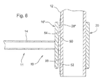
- Fig. 6 shows and alternate embodiment wherein the inner end of the needle 11 is defined by a clamp segment 16" having an inner surface 28" formed at a radius somewhat larger than the radius of the outer surface of the support member 12.
- Inserted between the clamp segment 16" and the support member 12 are two slightly tapered shims or wedges 50 and 52, having their thicker dimensioned ends engaged with each other at a central plane passing through the needle clamp segment 16".
- outer surfaces 54 and 56, respectively, of the shims 50 and 52 diverge from the inner surface 28" of the clamp segment 16" in opposite directions from the central plane.
- the shims 50 and 52 form a crown on the support member 12.
- a pair of shims could similarly be used to form a crown on the cylindrical inner surface 28" of the clamp segment 16", in which case the shims would have outer, cylindrically curved surfaces.
- a slightly tapered shim which extends lengthwise, completely through a gap defined between the clamp segment 16" and the outer surface of the support member 12 could be used, with the direction of insertion into the gap depending on the direction in which the needle 11 needs to be cocked in order to appropriately adjust its outer end.
Landscapes
- Life Sciences & Earth Sciences (AREA)
- Environmental Sciences (AREA)
- Surgical Instruments (AREA)
- Preliminary Treatment Of Fibers (AREA)
Abstract
Description
- The present invention relates to balers for making parallelepiped bales and more particularly relates to needle assemblies for such balers.
- Balers, both large and small, for forming parallelepiped bales typically use a needle assembly including a plurality of needles, cantilever-mounted to a transverse support member, to deliver twine through the bale chamber between adjacent ends of a just finished bale and starting bale to respective knotter mechanisms of a knotter assembly to complete the tie cycle on the finished bale and to start the next. Each of the needles must be accurately positioned at the top of its cycle in order to correctly place the twine in the associated knotter mechanism located on the opposite side of the bale chamber from the area occupied by the needles when the latter are in their at rest or standby position. The support member for the needles is typically mounted for swinging through an arc to move the needles as a unit. In addition to each of the needles having to be properly positioned for placing the twine into the associated knotter mechanism, needle position is also critical as the needles move through the arc because of the close proximity of baler components through which they must pass, e.g., the bale chamber floor and top, the plunger face, and the knotter assembly.
- On large balers, the cantilever connection of each needle is typically through a clamp arrangement. This can consist of two clamp segments that are clamped around a round tube. The length of the tube is perpendicular to the direction of travel of the needle mechanism during the tie cycle. One clamp segment is welded to the tube while the other defines an inner end of a needle. Each clamp segment has a generally semi-cylindrical surface sized to mate with the tube outer surface. The clamp segments each extend around less than half the circumference of the tube which leaves a space between the clamp segments when they are in position so that the clamp segment defining the inner end of the needle can be rotated relative to the tube. Four bolts, one on each corner of a given clamp arrangenent, are used to force the clamp against the tube to provide the desired clamping force. The fore-and-aft position of the needle tip can be adjusted by loosening the two bolts at one end of the clamp arrangement and tightening the opposite pair to rotate the needle clamp segment slightly around the clamp tube. Side-to-side needle tip adjustments however cannot be made in this fashion because the clamp-to-tube contact is solid in this direction. Heretofore, side-to-side needle tip adjustments have been made by physically bending each needle until it is correctly positioned.
- The problem to be solved then is how to construct a needle clamping arrangement so as to permit side-to-side needle adjustments as well as fore-and-aft adjustments.
- This problem is solved according to the invention by the teaching of claim 1 or 9 respectively, while features developing the solution in an advantageous manner are set forth in the further claims.
- According to the present invention there is provided a novel needle clamping arrangement.
- An object of the invention is to provide a needle clamping arrangement permitting both side-to-side needle adjustments, as well as fore-and-aft adjustments, of the needle tip. This object is accomplished by clamping arrangements wherein the interface between clamping surfaces of the clamping arrangement is shaped to permit side-to-side as well as fore-and-aft adjustments to be made to correctly position the needle tip.
- This and other objects will become apparent from a reading of the ensuing description together with the appended drawings.
- FIG. 1
- is a side view of a baler needle assembly constructed in accordance with the present invention.
- FIG. 2
- is a right side view of the baler needle assembly shown in
FIG. 1 , but showing only one needle and showing in broken lines positions at opposite sides of a desired position which the needle may assume before being adjusted. - FIG. 3
- is a perspective view showing the mounting clamp assembly securing the needle to the needle support member.
- FIG. 4
- is a sectional view taken horizontally through the mounting clamp assembly of
FIG. 3 . - FIG. 5
- is a sectional view like that of
FIG. 4 , but showing an alternate embodiment employing a separate mounting piece having an inner cylindrically shaped surface engaged with the needle carrier tube and having an outer surface which is generated by rotating a cylindrical segment about an axis located in a plane bisecting the clamp segment that is fixed to the needle support member. - FIG. 6
- is a sectional view like that of
FIG. 4 , but showing a further alternate embodiment employing a pair of generally semi-cylindrical, tapered shims having ends at their thicker dimensions abutting each other at a central plane passing through the needle. - Referring now to
FIG. 1 , there is shown atypical needle assembly 10 used in a baler for making parallelepiped bales. Theneedle assembly 10 includes a plurality of needles 11 (only one shown) mounted at spaced locations along a tubular cylindricalneedle support member 12, with the total number ofneedles 11 depending on the cross sectional dimension of a bale to be produced by the baler. As is well known, eachneedle 11 is responsible for delivering a strand of twine through the baling chamber of the baler and to an associated knotter mechanism so that the strand may be tied about a bale, which has reached a desired length in the baling chamber. - The
needle 11 includes an elongate,curved body 14 which increases in width from an inner end defined by afirst clamp segment 16 and an outer, twine- delivery end which carries aroller 18 that is used to engage and guide twine towards a knotter mechanism located on an opposite side of the baling chamber from a location where thesupport member 12 is mounted for swinging along an arcuate path between a standby position, wherein theneedles 11 are located with their outer twine-delivery ends withdrawn from, but adjacent to, the baling chamber, and a twine-delivery position, wherein the needles extend through the baling chamber with their outer ends being adjacent respective associated knotter mechanisms. Aclamp segment 20, here shown as a being identical in shape to theclamp segment 16, is welded in place on thesupport member 12. - As can best be seen in
FIG. 3 , each of theclamp segments bottom flanges inner surface 28 shaped substantially complementary to, and engaged with, a cylindrical exterior of thesupport member 12. Each of theflanges holes 30, with the four holes of each clamp half being elongated in a direction parallel with a longitudinal axis of thesupport member 12, arranged in a rectangular pattern, and respectively aligned with the four holes provided in the other clamp half. Abolt 32 is received in each pair of alignedholes 30, with ashoulder nut 34 and ajam nut 36 being received on a threaded end of eachbolt 32. Instead of fourbolts 32 being used, a clamp arrangement employing to U-bolts would work just as well. - Referring now to
FIG. 4 , it can be seen thatinner surface 28 of theclamp segment 16 is tapered from opposite ends to acrown 38 located in a plane in alignment with a plane passing centrally between opposite surfaces of theneedle body 14. This makes it possible to adjust the outer end of theneedle body 14 through a range shown in broken lines inFIG. 2 , by loosening the bolts located on one side of thecrown 38, while tightening the bolts on the other side of thecrown 38. Instead of, or in addition to, thecrown 38, a mirror image to thesurface 28 could be provided on thesupport member 12. -
FIG. 5 shows an alternative embodiment wherein the inner end of theneedle 11 is defined by aclamp segment 16" including an inner surface 28' including acentral surface section 42 shaped cylindrically about an axis extending in a direction perpendicular to a central axis of thesupport member 12. Seated against the cylindrically shapedcentral surface section 42 is a cylindrical outer surface of acrown member 44 having an interior surface shaped complementary to, and seated against, the cylindrical exterior of thetubular support member 12. Thecrown member 44 may be fixed to thesupport member 12, as by welding, for example, and thus may be considered part of the support member, or it may be provided as a separate piece. When the clamp segment 16' is disposed centrally on thecrown member 44,gaps 46 are defined between opposite ends of the inner surface 28' and thesupport member 12. If it is necessary to adjust the side-to-side position of the outer end of theneedle 11, this may be done by loosening thenuts bolts 32, adjusting the clamp segment 16' about the cylindrical surface of thecrown member 44 and re-tightening thenuts surface 42 being formed in the clamp segment 16', it could instead be provided as a cylindrically contoured groove in the exterior of thesupport member 12, with thecrown member 44 then being replaced by a similar member inverted so as to fit the cylindrical surface of the clamp segment 16' and the cylindrical groove provided in thesupport member 12. -
Fig. 6 shows and alternate embodiment wherein the inner end of theneedle 11 is defined by aclamp segment 16" having aninner surface 28" formed at a radius somewhat larger than the radius of the outer surface of thesupport member 12. Inserted between theclamp segment 16" and thesupport member 12 are two slightly tapered shims orwedges needle clamp segment 16". Thus,outer surfaces 54 and 56, respectively, of theshims inner surface 28" of theclamp segment 16" in opposite directions from the central plane. In effect, theshims support member 12. It will be appreciated that a pair of shims could similarly be used to form a crown on the cylindricalinner surface 28" of theclamp segment 16", in which case the shims would have outer, cylindrically curved surfaces. Alternatively, a slightly tapered shim which extends lengthwise, completely through a gap defined between theclamp segment 16" and the outer surface of thesupport member 12 could be used, with the direction of insertion into the gap depending on the direction in which theneedle 11 needs to be cocked in order to appropriately adjust its outer end. - Thus, it will be appreciated, that by providing an appropriate profile at a clamping surface arrangement of the
clamp segments support member 12, clamping forces can be applied to theclamp segments needle 11. - Having described the preferred embodiment, it will become apparent that various modifications can be made without departing from the scope of the invention as defined in the accompanying claims.
Claims (9)
- In a baler needle assembly (10) including a needle support member (12) extending transversely to a direction of movement of the needle support member (12), during a tying cycle, and a plurality of needles (11) mounted at spaced locations along said needle support member (12), each of said needles (11) being curved between an inner end and an outer twine-delivery end, a clamping arrangement securing said inner end of said needle (11) to said needle support member (12) and including a plurality of clamping bolts (32) carrying nuts (34, 36) which may be individually loosened and tightened, characterized in that at least one of said clamping arrangement and needle support member (12) includes clamping surfaces (28) configured such that by selectively loosening and tightening said plurality of clamping bolts (32) said twine delivery end of said needle (11) may be adjusted from side-to-side.
- The baler needle assembly according to claim 1, characterized in that said clamping arrangement includes a first clamp segment (16, 16', 16") defining said inner end of said needle (11) and said clamping surfaces (28, 28', 28") including a first surface of said first clamp segment (16, 16', 16") and a second surface extending lengthwise of said needle support member; a second clamp segment (20) engaging a third surface of said needle support member (12) located on a side opposite from said second surface; one of said first and second surfaces being crowned between opposite ends; and said plurality of clamping bolt assemblies including nut pairs (34, 36) located at opposite sides of said crown (38, 44) and being threaded onto bolt ends for clamping said first and second clamp segments (16, 16', 16", 20) together for causing said first clamp segment (16; 16', 16") to tilt about said crown (38, 44), thereby resulting in side-to-side adjustment of said twine delivery end of the needle (11).
- The baler needle assembly according to claim 1, characterized in that said inner end of said needle (11) is defined by a first clamp segment (16, 16', 16") having an inner surface (28, 28', 28") disposed for being clamped against a first location of said needle support member (12), with the inner surface (28, 28', 28") of the first clamp segment (16, 16', 16") being joined to oppositely extending first and second flanges (24, 26), a second clamp segment (20) being engaged with said needle support member (12) at a second location of said needle support member (12), which is directly opposite from said first location, with said second clamp segment (20) having third and fourth oppositely extending flanges (24, 26) respectively located in opposing relationship to said first and second flanges (24, 26), said first and third flanges (24) containing first and second sets of aligned mounting holes (30), and said second and fourth flanges (26) containing third and fourth sets (26) of aligned mounting holes (30); said first nut (34, 36) and bolt (32) pair being associated with said first and third sets of mounting holes (30) and said second nut (34, 36) and bolt (32) pair being associated with said second and fourth sets of mounting holes (30); and said first location of said clamp needle support member (12) and said inner surface (28, 28', 28") of said first clamp segment (16, 16', 16") being so configured and arranged so as to define said crown (38, 44) permitting said first clamp (16, 16', 16") segment to be tilted about said crown (38, 44) so as to effect said side-to-side adjustment of said twine delivery end of said needle (11).
- The baler needle assembly, as defined in claim 2, wherein said needle (11) is symmetrical about a central plane passing midway between opposite ends of said first clamp segment (16, 16', 16"); and said first clamp segment (16, 16'. 16") including an inner surface (28, 28', 28") having said crown (38, 44) located at said central plane such that, when said crown (38, 44) is in contact with said needle support member (12), an increasing clearance is provided between said inner surface of said first clamp segment (16, 16', 16") and said needle support member (12) in opposite directions from said crown (38, 44).
- The baler needle assembly, as defined in claim 1, wherein said inner end of said needle (11) is defined by a first clamp segment (16, 16', 16") symmetrical about a central plane passing midway between opposite ends of said first clamp segment (16, 16', 16"); and said clamping arrangement including one of said inner surface (28, 28', 28") of said first clamp segment (16, 16', 16") and said first location of said support member (12) including a first region which is concave in cross section, and another of said inner surface of said first clamp segment (16, 16', 16") and said first location of said needle support (12) including a second region shaped complementary to said central region of said inner surface (28, 28', 28") of said first clamp segment (16, 16', 16").
- The baler needle assembly, as defined in claim 5, wherein said second region of said needle support (12) member is a ball segment.
- The baler needle assembly, as defined in claim 1, wherein said clamping arrangement includes said needle support (12) having a substantially cylindrical outer surface and includes said inner end of said needle (11) being defined by a clamp segment (16, 16', 16") having an inner surface (28, 28', 28") formed at a radius larger than that of said cylindrical outer surface of said needle support (12) so as to define a gap between said inner surface (28, 28', 28") of said first clamp segment (16, 16', 16") and said cylindrical outer surface; and said clamping arrangement further including a tapered shim arrangement located in said gap so as to define at least one inclined surface against which said clamp segment (16, 16', 16") of said needle (11) may be clamped so as to effect side-to-side adjustment of said outer end of the needle (11).
- The baler needle assembly, as defined in claim 7, wherein said tapered shim arrangement includes a pair of shims (50, 52) having thicker dimensioned ends located in abutting relationship with each other at a central location between opposite ends of said clamp segment (16, 16'; 16") of said needle (11).
- A baler for forming parallelepiped bales comprising at least one baler needle assembly according to one or several of the previous claims.
Priority Applications (1)
| Application Number | Priority Date | Filing Date | Title |
|---|---|---|---|
| PL08100710T PL1955585T3 (en) | 2007-02-09 | 2008-01-21 | Baler needle assembly and baler |
Applications Claiming Priority (1)
| Application Number | Priority Date | Filing Date | Title |
|---|---|---|---|
| US11/673,216 US7458620B2 (en) | 2007-02-09 | 2007-02-09 | Baler needle clamp arrangement for facilitating side-to-side adjustment of outer needle end |
Publications (2)
| Publication Number | Publication Date |
|---|---|
| EP1955585A1 true EP1955585A1 (en) | 2008-08-13 |
| EP1955585B1 EP1955585B1 (en) | 2015-12-09 |
Family
ID=39412337
Family Applications (1)
| Application Number | Title | Priority Date | Filing Date |
|---|---|---|---|
| EP08100710.6A Active EP1955585B1 (en) | 2007-02-09 | 2008-01-21 | Baler needle assembly and baler |
Country Status (3)
| Country | Link |
|---|---|
| US (1) | US7458620B2 (en) |
| EP (1) | EP1955585B1 (en) |
| PL (1) | PL1955585T3 (en) |
Cited By (1)
| Publication number | Priority date | Publication date | Assignee | Title |
|---|---|---|---|---|
| EP2944181A1 (en) * | 2014-05-07 | 2015-11-18 | Deere & Company | A lift link assembly for coupling a baler needle |
Families Citing this family (12)
| Publication number | Priority date | Publication date | Assignee | Title |
|---|---|---|---|---|
| GB2450716A (en) * | 2007-07-04 | 2009-01-07 | Cnh Belgium Nv | Improvements in square balers |
| US9498795B2 (en) | 2013-09-11 | 2016-11-22 | Building Materials Investment Corporation | Method and apparatus for sharp color definition on the application of granules to roofing substrates |
| US9145084B2 (en) * | 2013-09-18 | 2015-09-29 | Omix-Ada, Inc. | Auxiliary light mount assembly for tubular bumpers |
| US9936646B2 (en) | 2014-11-12 | 2018-04-10 | Deere & Company | Light weight needle construction for delivering twine in a large square baler |
| US10588265B2 (en) | 2016-10-31 | 2020-03-17 | Deere & Company | Individual needle protection system |
| CN107839920B (en) * | 2017-12-06 | 2024-03-19 | 浙江万纳核电检修有限公司 | Combined tool for fire hose binding and use method of combined tool |
| USD887260S1 (en) * | 2018-05-30 | 2020-06-16 | Omix-Ada, Inc. | Grab handle |
| US11240965B2 (en) * | 2018-11-01 | 2022-02-08 | Deere & Company | Multi-material needle for square balers |
| US11457567B2 (en) * | 2019-07-01 | 2022-10-04 | Deere & Company | Needle coupling and frame assembly for agricultural machine |
| US11412662B2 (en) * | 2019-07-01 | 2022-08-16 | Deere & Company | Needle frame yoke and arm assembly for agricultural machine |
| US11419273B2 (en) * | 2019-07-01 | 2022-08-23 | Deere & Company | Needle frame assembly and needle coupling for agricultural machine |
| DE102023124000A1 (en) * | 2023-09-06 | 2025-03-06 | Maschinenfabrik Bernard Krone GmbH & Co. KG | TYING NEEDLE FOR A NEEDLE SWING OF A BALER |
Citations (3)
| Publication number | Priority date | Publication date | Assignee | Title |
|---|---|---|---|---|
| US3036514A (en) | 1960-11-29 | 1962-05-29 | Sperry Rand Corp | Hay baler |
| US4102261A (en) * | 1977-02-11 | 1978-07-25 | Hesston Corporation | Adjustable mounting for tying needles |
| DE4124308A1 (en) * | 1991-07-23 | 1993-01-28 | Fortschritt Erntemaschinen | Binding needle for large bales - has forked end secured to wing and with adjusting screws on either side |
Family Cites Families (6)
| Publication number | Priority date | Publication date | Assignee | Title |
|---|---|---|---|---|
| US2287761A (en) * | 1940-07-17 | 1942-06-23 | Burndy Engineering Co Inc | Electrical cable connector |
| US2547932A (en) * | 1946-11-08 | 1951-04-10 | Jr Alfred B Downs | Ground clamp for electrical circuits |
| US3550969A (en) * | 1967-10-16 | 1970-12-29 | Mayes R Robinson | Tool clamp for agricultural machinery |
| US4102260A (en) * | 1977-02-11 | 1978-07-25 | Hesston Corporation | Cantilevered tying needle construction for crop balers |
| US4463668A (en) * | 1983-01-14 | 1984-08-07 | Sperry Corporation | Baler twine needle with breakoff tip portion |
| US7309054B2 (en) * | 2003-05-27 | 2007-12-18 | Taco Metals, Inc. | Universal clamp |
-
2007
- 2007-02-09 US US11/673,216 patent/US7458620B2/en active Active
-
2008
- 2008-01-21 EP EP08100710.6A patent/EP1955585B1/en active Active
- 2008-01-21 PL PL08100710T patent/PL1955585T3/en unknown
Patent Citations (3)
| Publication number | Priority date | Publication date | Assignee | Title |
|---|---|---|---|---|
| US3036514A (en) | 1960-11-29 | 1962-05-29 | Sperry Rand Corp | Hay baler |
| US4102261A (en) * | 1977-02-11 | 1978-07-25 | Hesston Corporation | Adjustable mounting for tying needles |
| DE4124308A1 (en) * | 1991-07-23 | 1993-01-28 | Fortschritt Erntemaschinen | Binding needle for large bales - has forked end secured to wing and with adjusting screws on either side |
Cited By (1)
| Publication number | Priority date | Publication date | Assignee | Title |
|---|---|---|---|---|
| EP2944181A1 (en) * | 2014-05-07 | 2015-11-18 | Deere & Company | A lift link assembly for coupling a baler needle |
Also Published As
| Publication number | Publication date |
|---|---|
| EP1955585B1 (en) | 2015-12-09 |
| PL1955585T3 (en) | 2016-04-29 |
| US7458620B2 (en) | 2008-12-02 |
| US20080190306A1 (en) | 2008-08-14 |
Similar Documents
| Publication | Publication Date | Title |
|---|---|---|
| EP1955585B1 (en) | Baler needle assembly and baler | |
| US10117677B2 (en) | Fixation clamp | |
| US6423064B1 (en) | Orthopaedic screw variable angle connection to a longitudinal support | |
| US20090182378A1 (en) | Flexible rod for fixing vertebrae | |
| EP2384616B1 (en) | Pickup device on harvesting machines | |
| US9295492B2 (en) | Fixation clamp | |
| AT514980A1 (en) | Swivel bearing and conveyor roller for an oblique installation of the same in a conveyor system | |
| EP2633924B1 (en) | Flip-flow screen | |
| DE102008024915B3 (en) | Conveyor belt steering device for tubular belt conveyor for position correction of conveyor belt in closed condition, has adjustment mechanism, where geometry of mechanism is selected such that lower carrier roller causes steering movement | |
| CA2522514A1 (en) | Breaker bar | |
| AU756799B2 (en) | A nail machine, and a tool ring and fitting for securing holding jaws for such machine | |
| AT519606B1 (en) | bearing cap | |
| DE4024494A1 (en) | SPRING JOINT FOR SWIVELING CONNECTION OF TWO BODIES | |
| CA2563547C (en) | Elastic element produced from radiolucent material for a medical device | |
| US9532507B2 (en) | Guide system for a plunger of a rectangular baler | |
| EP3925434B1 (en) | A crank-operated packer mechanism for an agricultural baler | |
| WO2019091701A1 (en) | Stator assembly for an eccentric screw pump | |
| EP4331345A1 (en) | Attachment device | |
| EP3724625B1 (en) | Linear force-measuring device and hydraulic actuator | |
| DE68906451T2 (en) | Ammunition guide channel for machine guns. | |
| EP1586872A1 (en) | Vibrator-type level meter | |
| US3320875A (en) | Agricultural apparatus | |
| KR200382868Y1 (en) | A cross bar connection apparatus to be used in spinal fixation system | |
| JP5512361B2 (en) | Ball goal | |
| EP0278101A1 (en) | Hay making machine |
Legal Events
| Date | Code | Title | Description |
|---|---|---|---|
| PUAI | Public reference made under article 153(3) epc to a published international application that has entered the european phase |
Free format text: ORIGINAL CODE: 0009012 |
|
| AK | Designated contracting states |
Kind code of ref document: A1 Designated state(s): AT BE BG CH CY CZ DE DK EE ES FI FR GB GR HR HU IE IS IT LI LT LU LV MC MT NL NO PL PT RO SE SI SK TR |
|
| AX | Request for extension of the european patent |
Extension state: AL BA MK RS |
|
| 17P | Request for examination filed |
Effective date: 20090213 |
|
| AKX | Designation fees paid |
Designated state(s): AT BE BG CH CY CZ DE DK EE ES FI FR GB GR HR HU IE IS IT LI LT LU LV MC MT NL NO PL PT RO SE SI SK TR |
|
| 17Q | First examination report despatched |
Effective date: 20090327 |
|
| GRAP | Despatch of communication of intention to grant a patent |
Free format text: ORIGINAL CODE: EPIDOSNIGR1 |
|
| INTG | Intention to grant announced |
Effective date: 20150629 |
|
| GRAS | Grant fee paid |
Free format text: ORIGINAL CODE: EPIDOSNIGR3 |
|
| GRAA | (expected) grant |
Free format text: ORIGINAL CODE: 0009210 |
|
| AK | Designated contracting states |
Kind code of ref document: B1 Designated state(s): AT BE BG CH CY CZ DE DK EE ES FI FR GB GR HR HU IE IS IT LI LT LU LV MC MT NL NO PL PT RO SE SI SK TR |
|
| REG | Reference to a national code |
Ref country code: GB Ref legal event code: FG4D |
|
| REG | Reference to a national code |
Ref country code: AT Ref legal event code: REF Ref document number: 764115 Country of ref document: AT Kind code of ref document: T Effective date: 20151215 Ref country code: CH Ref legal event code: EP |
|
| REG | Reference to a national code |
Ref country code: IE Ref legal event code: FG4D |
|
| REG | Reference to a national code |
Ref country code: DE Ref legal event code: R096 Ref document number: 602008041500 Country of ref document: DE |
|
| REG | Reference to a national code |
Ref country code: FR Ref legal event code: PLFP Year of fee payment: 9 |
|
| REG | Reference to a national code |
Ref country code: LT Ref legal event code: MG4D |
|
| REG | Reference to a national code |
Ref country code: NL Ref legal event code: MP Effective date: 20151209 |
|
| PG25 | Lapsed in a contracting state [announced via postgrant information from national office to epo] |
Ref country code: LT Free format text: LAPSE BECAUSE OF FAILURE TO SUBMIT A TRANSLATION OF THE DESCRIPTION OR TO PAY THE FEE WITHIN THE PRESCRIBED TIME-LIMIT Effective date: 20151209 Ref country code: NO Free format text: LAPSE BECAUSE OF FAILURE TO SUBMIT A TRANSLATION OF THE DESCRIPTION OR TO PAY THE FEE WITHIN THE PRESCRIBED TIME-LIMIT Effective date: 20160309 Ref country code: ES Free format text: LAPSE BECAUSE OF FAILURE TO SUBMIT A TRANSLATION OF THE DESCRIPTION OR TO PAY THE FEE WITHIN THE PRESCRIBED TIME-LIMIT Effective date: 20151209 |
|
| REG | Reference to a national code |
Ref country code: AT Ref legal event code: MK05 Ref document number: 764115 Country of ref document: AT Kind code of ref document: T Effective date: 20151209 |
|
| PG25 | Lapsed in a contracting state [announced via postgrant information from national office to epo] |
Ref country code: GR Free format text: LAPSE BECAUSE OF FAILURE TO SUBMIT A TRANSLATION OF THE DESCRIPTION OR TO PAY THE FEE WITHIN THE PRESCRIBED TIME-LIMIT Effective date: 20160310 Ref country code: NL Free format text: LAPSE BECAUSE OF FAILURE TO SUBMIT A TRANSLATION OF THE DESCRIPTION OR TO PAY THE FEE WITHIN THE PRESCRIBED TIME-LIMIT Effective date: 20151209 Ref country code: BE Free format text: LAPSE BECAUSE OF NON-PAYMENT OF DUE FEES Effective date: 20160131 Ref country code: SE Free format text: LAPSE BECAUSE OF FAILURE TO SUBMIT A TRANSLATION OF THE DESCRIPTION OR TO PAY THE FEE WITHIN THE PRESCRIBED TIME-LIMIT Effective date: 20151209 Ref country code: LV Free format text: LAPSE BECAUSE OF FAILURE TO SUBMIT A TRANSLATION OF THE DESCRIPTION OR TO PAY THE FEE WITHIN THE PRESCRIBED TIME-LIMIT Effective date: 20151209 Ref country code: FI Free format text: LAPSE BECAUSE OF FAILURE TO SUBMIT A TRANSLATION OF THE DESCRIPTION OR TO PAY THE FEE WITHIN THE PRESCRIBED TIME-LIMIT Effective date: 20151209 |
|
| PG25 | Lapsed in a contracting state [announced via postgrant information from national office to epo] |
Ref country code: IS Free format text: LAPSE BECAUSE OF FAILURE TO SUBMIT A TRANSLATION OF THE DESCRIPTION OR TO PAY THE FEE WITHIN THE PRESCRIBED TIME-LIMIT Effective date: 20151209 |
|
| PG25 | Lapsed in a contracting state [announced via postgrant information from national office to epo] |
Ref country code: IT Free format text: LAPSE BECAUSE OF FAILURE TO SUBMIT A TRANSLATION OF THE DESCRIPTION OR TO PAY THE FEE WITHIN THE PRESCRIBED TIME-LIMIT Effective date: 20151209 Ref country code: CZ Free format text: LAPSE BECAUSE OF FAILURE TO SUBMIT A TRANSLATION OF THE DESCRIPTION OR TO PAY THE FEE WITHIN THE PRESCRIBED TIME-LIMIT Effective date: 20151209 |
|
| PG25 | Lapsed in a contracting state [announced via postgrant information from national office to epo] |
Ref country code: PT Free format text: LAPSE BECAUSE OF FAILURE TO SUBMIT A TRANSLATION OF THE DESCRIPTION OR TO PAY THE FEE WITHIN THE PRESCRIBED TIME-LIMIT Effective date: 20160411 Ref country code: AT Free format text: LAPSE BECAUSE OF FAILURE TO SUBMIT A TRANSLATION OF THE DESCRIPTION OR TO PAY THE FEE WITHIN THE PRESCRIBED TIME-LIMIT Effective date: 20151209 Ref country code: EE Free format text: LAPSE BECAUSE OF FAILURE TO SUBMIT A TRANSLATION OF THE DESCRIPTION OR TO PAY THE FEE WITHIN THE PRESCRIBED TIME-LIMIT Effective date: 20151209 Ref country code: LU Free format text: LAPSE BECAUSE OF FAILURE TO SUBMIT A TRANSLATION OF THE DESCRIPTION OR TO PAY THE FEE WITHIN THE PRESCRIBED TIME-LIMIT Effective date: 20160121 Ref country code: RO Free format text: LAPSE BECAUSE OF FAILURE TO SUBMIT A TRANSLATION OF THE DESCRIPTION OR TO PAY THE FEE WITHIN THE PRESCRIBED TIME-LIMIT Effective date: 20151209 Ref country code: SK Free format text: LAPSE BECAUSE OF FAILURE TO SUBMIT A TRANSLATION OF THE DESCRIPTION OR TO PAY THE FEE WITHIN THE PRESCRIBED TIME-LIMIT Effective date: 20151209 Ref country code: IS Free format text: LAPSE BECAUSE OF FAILURE TO SUBMIT A TRANSLATION OF THE DESCRIPTION OR TO PAY THE FEE WITHIN THE PRESCRIBED TIME-LIMIT Effective date: 20160409 |
|
| REG | Reference to a national code |
Ref country code: CH Ref legal event code: PL |
|
| REG | Reference to a national code |
Ref country code: DE Ref legal event code: R097 Ref document number: 602008041500 Country of ref document: DE |
|
| PG25 | Lapsed in a contracting state [announced via postgrant information from national office to epo] |
Ref country code: MC Free format text: LAPSE BECAUSE OF FAILURE TO SUBMIT A TRANSLATION OF THE DESCRIPTION OR TO PAY THE FEE WITHIN THE PRESCRIBED TIME-LIMIT Effective date: 20151209 |
|
| PLBE | No opposition filed within time limit |
Free format text: ORIGINAL CODE: 0009261 |
|
| STAA | Information on the status of an ep patent application or granted ep patent |
Free format text: STATUS: NO OPPOSITION FILED WITHIN TIME LIMIT |
|
| PG25 | Lapsed in a contracting state [announced via postgrant information from national office to epo] |
Ref country code: LI Free format text: LAPSE BECAUSE OF NON-PAYMENT OF DUE FEES Effective date: 20160131 Ref country code: CH Free format text: LAPSE BECAUSE OF NON-PAYMENT OF DUE FEES Effective date: 20160131 Ref country code: DK Free format text: LAPSE BECAUSE OF FAILURE TO SUBMIT A TRANSLATION OF THE DESCRIPTION OR TO PAY THE FEE WITHIN THE PRESCRIBED TIME-LIMIT Effective date: 20151209 |
|
| 26N | No opposition filed |
Effective date: 20160912 |
|
| GBPC | Gb: european patent ceased through non-payment of renewal fee |
Effective date: 20160309 |
|
| PG25 | Lapsed in a contracting state [announced via postgrant information from national office to epo] |
Ref country code: SI Free format text: LAPSE BECAUSE OF FAILURE TO SUBMIT A TRANSLATION OF THE DESCRIPTION OR TO PAY THE FEE WITHIN THE PRESCRIBED TIME-LIMIT Effective date: 20151209 |
|
| PG25 | Lapsed in a contracting state [announced via postgrant information from national office to epo] |
Ref country code: BE Free format text: LAPSE BECAUSE OF FAILURE TO SUBMIT A TRANSLATION OF THE DESCRIPTION OR TO PAY THE FEE WITHIN THE PRESCRIBED TIME-LIMIT Effective date: 20151209 |
|
| REG | Reference to a national code |
Ref country code: FR Ref legal event code: PLFP Year of fee payment: 10 |
|
| PG25 | Lapsed in a contracting state [announced via postgrant information from national office to epo] |
Ref country code: GB Free format text: LAPSE BECAUSE OF NON-PAYMENT OF DUE FEES Effective date: 20160309 |
|
| PG25 | Lapsed in a contracting state [announced via postgrant information from national office to epo] |
Ref country code: MT Free format text: LAPSE BECAUSE OF FAILURE TO SUBMIT A TRANSLATION OF THE DESCRIPTION OR TO PAY THE FEE WITHIN THE PRESCRIBED TIME-LIMIT Effective date: 20151209 |
|
| REG | Reference to a national code |
Ref country code: FR Ref legal event code: PLFP Year of fee payment: 11 |
|
| PG25 | Lapsed in a contracting state [announced via postgrant information from national office to epo] |
Ref country code: CY Free format text: LAPSE BECAUSE OF FAILURE TO SUBMIT A TRANSLATION OF THE DESCRIPTION OR TO PAY THE FEE WITHIN THE PRESCRIBED TIME-LIMIT Effective date: 20151209 Ref country code: HU Free format text: LAPSE BECAUSE OF FAILURE TO SUBMIT A TRANSLATION OF THE DESCRIPTION OR TO PAY THE FEE WITHIN THE PRESCRIBED TIME-LIMIT; INVALID AB INITIO Effective date: 20080121 |
|
| PGFP | Annual fee paid to national office [announced via postgrant information from national office to epo] |
Ref country code: IE Payment date: 20180129 Year of fee payment: 11 Ref country code: PL Payment date: 20180104 Year of fee payment: 11 |
|
| PG25 | Lapsed in a contracting state [announced via postgrant information from national office to epo] |
Ref country code: HR Free format text: LAPSE BECAUSE OF FAILURE TO SUBMIT A TRANSLATION OF THE DESCRIPTION OR TO PAY THE FEE WITHIN THE PRESCRIBED TIME-LIMIT Effective date: 20151209 Ref country code: MT Free format text: LAPSE BECAUSE OF FAILURE TO SUBMIT A TRANSLATION OF THE DESCRIPTION OR TO PAY THE FEE WITHIN THE PRESCRIBED TIME-LIMIT Effective date: 20160131 Ref country code: TR Free format text: LAPSE BECAUSE OF FAILURE TO SUBMIT A TRANSLATION OF THE DESCRIPTION OR TO PAY THE FEE WITHIN THE PRESCRIBED TIME-LIMIT Effective date: 20151209 |
|
| PG25 | Lapsed in a contracting state [announced via postgrant information from national office to epo] |
Ref country code: BG Free format text: LAPSE BECAUSE OF FAILURE TO SUBMIT A TRANSLATION OF THE DESCRIPTION OR TO PAY THE FEE WITHIN THE PRESCRIBED TIME-LIMIT Effective date: 20151209 |
|
| REG | Reference to a national code |
Ref country code: IE Ref legal event code: MM4A |
|
| PG25 | Lapsed in a contracting state [announced via postgrant information from national office to epo] |
Ref country code: IE Free format text: LAPSE BECAUSE OF NON-PAYMENT OF DUE FEES Effective date: 20190121 |
|
| PG25 | Lapsed in a contracting state [announced via postgrant information from national office to epo] |
Ref country code: PL Free format text: LAPSE BECAUSE OF NON-PAYMENT OF DUE FEES Effective date: 20190121 |
|
| PGFP | Annual fee paid to national office [announced via postgrant information from national office to epo] |
Ref country code: DE Payment date: 20241219 Year of fee payment: 18 |
|
| PGFP | Annual fee paid to national office [announced via postgrant information from national office to epo] |
Ref country code: FR Payment date: 20250127 Year of fee payment: 18 |