EP1954616B1 - Device for depositing sheets - Google Patents
Device for depositing sheets Download PDFInfo
- Publication number
- EP1954616B1 EP1954616B1 EP06762221A EP06762221A EP1954616B1 EP 1954616 B1 EP1954616 B1 EP 1954616B1 EP 06762221 A EP06762221 A EP 06762221A EP 06762221 A EP06762221 A EP 06762221A EP 1954616 B1 EP1954616 B1 EP 1954616B1
- Authority
- EP
- European Patent Office
- Prior art keywords
- sheets
- deposit
- angle
- tray
- approximately
- Prior art date
- Legal status (The legal status is an assumption and is not a legal conclusion. Google has not performed a legal analysis and makes no representation as to the accuracy of the status listed.)
- Not-in-force
Links
- 238000000151 deposition Methods 0.000 title claims abstract description 18
- 238000000034 method Methods 0.000 claims abstract description 4
- 238000012546 transfer Methods 0.000 claims description 4
- 238000011144 upstream manufacturing Methods 0.000 claims description 4
- 238000012545 processing Methods 0.000 abstract description 4
- 238000012986 modification Methods 0.000 description 10
- 230000004048 modification Effects 0.000 description 10
- 238000013461 design Methods 0.000 description 2
- 239000000463 material Substances 0.000 description 2
- 230000002787 reinforcement Effects 0.000 description 2
- 230000000630 rising effect Effects 0.000 description 2
- 239000000725 suspension Substances 0.000 description 2
- 230000015572 biosynthetic process Effects 0.000 description 1
- 230000006378 damage Effects 0.000 description 1
- 230000001419 dependent effect Effects 0.000 description 1
- 238000001514 detection method Methods 0.000 description 1
- 230000000694 effects Effects 0.000 description 1
- 125000006850 spacer group Chemical group 0.000 description 1
- 238000012360 testing method Methods 0.000 description 1
Images





Classifications
-
- B—PERFORMING OPERATIONS; TRANSPORTING
- B65—CONVEYING; PACKING; STORING; HANDLING THIN OR FILAMENTARY MATERIAL
- B65H—HANDLING THIN OR FILAMENTARY MATERIAL, e.g. SHEETS, WEBS, CABLES
- B65H31/00—Pile receivers
- B65H31/02—Pile receivers with stationary end support against which pile accumulates
-
- B—PERFORMING OPERATIONS; TRANSPORTING
- B65—CONVEYING; PACKING; STORING; HANDLING THIN OR FILAMENTARY MATERIAL
- B65H—HANDLING THIN OR FILAMENTARY MATERIAL, e.g. SHEETS, WEBS, CABLES
- B65H31/00—Pile receivers
- B65H31/04—Pile receivers with movable end support arranged to recede as pile accumulates
- B65H31/08—Pile receivers with movable end support arranged to recede as pile accumulates the articles being piled one above another
- B65H31/10—Pile receivers with movable end support arranged to recede as pile accumulates the articles being piled one above another and applied at the top of the pile
-
- B—PERFORMING OPERATIONS; TRANSPORTING
- B65—CONVEYING; PACKING; STORING; HANDLING THIN OR FILAMENTARY MATERIAL
- B65H—HANDLING THIN OR FILAMENTARY MATERIAL, e.g. SHEETS, WEBS, CABLES
- B65H31/00—Pile receivers
- B65H31/20—Pile receivers adjustable for different article sizes
-
- B—PERFORMING OPERATIONS; TRANSPORTING
- B65—CONVEYING; PACKING; STORING; HANDLING THIN OR FILAMENTARY MATERIAL
- B65H—HANDLING THIN OR FILAMENTARY MATERIAL, e.g. SHEETS, WEBS, CABLES
- B65H31/00—Pile receivers
- B65H31/34—Apparatus for squaring-up piled articles
-
- B—PERFORMING OPERATIONS; TRANSPORTING
- B65—CONVEYING; PACKING; STORING; HANDLING THIN OR FILAMENTARY MATERIAL
- B65H—HANDLING THIN OR FILAMENTARY MATERIAL, e.g. SHEETS, WEBS, CABLES
- B65H2301/00—Handling processes for sheets or webs
- B65H2301/40—Type of handling process
- B65H2301/42—Piling, depiling, handling piles
- B65H2301/421—Forming a pile
-
- B—PERFORMING OPERATIONS; TRANSPORTING
- B65—CONVEYING; PACKING; STORING; HANDLING THIN OR FILAMENTARY MATERIAL
- B65H—HANDLING THIN OR FILAMENTARY MATERIAL, e.g. SHEETS, WEBS, CABLES
- B65H2404/00—Parts for transporting or guiding the handled material
- B65H2404/60—Other elements in face contact with handled material
- B65H2404/61—Longitudinally-extending strips, tubes, plates, or wires
- B65H2404/611—Longitudinally-extending strips, tubes, plates, or wires arranged to form a channel
- B65H2404/6112—Longitudinally-extending strips, tubes, plates, or wires arranged to form a channel and displaceable for changing direction of transport
-
- B—PERFORMING OPERATIONS; TRANSPORTING
- B65—CONVEYING; PACKING; STORING; HANDLING THIN OR FILAMENTARY MATERIAL
- B65H—HANDLING THIN OR FILAMENTARY MATERIAL, e.g. SHEETS, WEBS, CABLES
- B65H2404/00—Parts for transporting or guiding the handled material
- B65H2404/60—Other elements in face contact with handled material
- B65H2404/65—Other elements in face contact with handled material rotating around an axis parallel to face of material and perpendicular to transport direction, e.g. star wheel
-
- B—PERFORMING OPERATIONS; TRANSPORTING
- B65—CONVEYING; PACKING; STORING; HANDLING THIN OR FILAMENTARY MATERIAL
- B65H—HANDLING THIN OR FILAMENTARY MATERIAL, e.g. SHEETS, WEBS, CABLES
- B65H2404/00—Parts for transporting or guiding the handled material
- B65H2404/70—Other elements in edge contact with handled material, e.g. registering, orientating, guiding devices
- B65H2404/74—Guiding means
- B65H2404/741—Guiding means movable in operation
- B65H2404/7414—Guiding means movable in operation pivotable
-
- B—PERFORMING OPERATIONS; TRANSPORTING
- B65—CONVEYING; PACKING; STORING; HANDLING THIN OR FILAMENTARY MATERIAL
- B65H—HANDLING THIN OR FILAMENTARY MATERIAL, e.g. SHEETS, WEBS, CABLES
- B65H2405/00—Parts for holding the handled material
- B65H2405/10—Cassettes, holders, bins, decks, trays, supports or magazines for sheets stacked substantially horizontally
- B65H2405/11—Parts and details thereof
- B65H2405/111—Bottom
- B65H2405/1111—Bottom with several surface portions forming an angle relatively to each other
-
- B—PERFORMING OPERATIONS; TRANSPORTING
- B65—CONVEYING; PACKING; STORING; HANDLING THIN OR FILAMENTARY MATERIAL
- B65H—HANDLING THIN OR FILAMENTARY MATERIAL, e.g. SHEETS, WEBS, CABLES
- B65H2405/00—Parts for holding the handled material
- B65H2405/10—Cassettes, holders, bins, decks, trays, supports or magazines for sheets stacked substantially horizontally
- B65H2405/11—Parts and details thereof
- B65H2405/111—Bottom
- B65H2405/1115—Bottom with surface inclined, e.g. in width-wise direction
-
- B—PERFORMING OPERATIONS; TRANSPORTING
- B65—CONVEYING; PACKING; STORING; HANDLING THIN OR FILAMENTARY MATERIAL
- B65H—HANDLING THIN OR FILAMENTARY MATERIAL, e.g. SHEETS, WEBS, CABLES
- B65H2405/00—Parts for holding the handled material
- B65H2405/10—Cassettes, holders, bins, decks, trays, supports or magazines for sheets stacked substantially horizontally
- B65H2405/11—Parts and details thereof
- B65H2405/111—Bottom
- B65H2405/1115—Bottom with surface inclined, e.g. in width-wise direction
- B65H2405/11151—Bottom with surface inclined, e.g. in width-wise direction with surface inclined upwardly in transport direction
-
- B—PERFORMING OPERATIONS; TRANSPORTING
- B65—CONVEYING; PACKING; STORING; HANDLING THIN OR FILAMENTARY MATERIAL
- B65H—HANDLING THIN OR FILAMENTARY MATERIAL, e.g. SHEETS, WEBS, CABLES
- B65H2405/00—Parts for holding the handled material
- B65H2405/10—Cassettes, holders, bins, decks, trays, supports or magazines for sheets stacked substantially horizontally
- B65H2405/11—Parts and details thereof
- B65H2405/112—Rear, i.e. portion opposite to the feeding / delivering side
- B65H2405/1122—Rear, i.e. portion opposite to the feeding / delivering side movable linearly, details therefor
-
- B—PERFORMING OPERATIONS; TRANSPORTING
- B65—CONVEYING; PACKING; STORING; HANDLING THIN OR FILAMENTARY MATERIAL
- B65H—HANDLING THIN OR FILAMENTARY MATERIAL, e.g. SHEETS, WEBS, CABLES
- B65H2701/00—Handled material; Storage means
- B65H2701/10—Handled articles or webs
- B65H2701/13—Parts concerned of the handled material
- B65H2701/131—Edges
- B65H2701/1315—Edges side edges, i.e. regarded in context of transport
-
- B—PERFORMING OPERATIONS; TRANSPORTING
- B65—CONVEYING; PACKING; STORING; HANDLING THIN OR FILAMENTARY MATERIAL
- B65H—HANDLING THIN OR FILAMENTARY MATERIAL, e.g. SHEETS, WEBS, CABLES
- B65H2801/00—Application field
- B65H2801/03—Image reproduction devices
- B65H2801/06—Office-type machines, e.g. photocopiers
Definitions
- the invention relates to a device for depositing sheets in a machine that preferably processes sheets by graphic means, in particular for a printing machine, preferably for an electrophotographically operating machine, comprising at least one deposit tray for depositing and preferably also for stacking processed sheets.
- Document DE 101 54 743 A1 discloses, among other things, a simple design of a support tray for a stack of sheets, which tray may optionally also be a component of a device of the aforementioned type and be specifically arranged on the delivery side of a printing machine.
- U.S.Patent No. 4,605,211 discloses an automatic sheet processing device having a simple and compact structure, and in which alignment and binding of sheets are ensured with a high reliability.
- sheets of the most diverse kind are to be processed, for example, sheets having a different weight per unit area, different size, different surface finish and the like, specifically, because a particular advantage of electrophotgraphic printing is that printing may be personalized and customized. Therefore, printing jobs may also be carried out which include a great variety of different printing materials. However, at the same time, there is the demand for carrying out such printing jobs more rapidly and more cost-effectively than before.
- the object of the invention is to provide a device or a deposit tray of the aforementioned type, which permits a controlled depositing and stacking of sheets, in particular, at greater sheet-processing speeds, and, preferably, in a cost-effective manner.
- this object is achieved with a device for depositing sheets cooperating with a machine, as defined in claims 1 and 10, in that a deposit surface of the deposit tray is arranged, or can be arranged, at an angle that deviates from the horizontal.
- a deposit surface of the deposit tray is arranged, or can be arranged, at an angle that deviates from the horizontal.
- An inventive setting angle can advantageously be adapted, in particular, to the sheet quality and the sheet transport speed, in which case this angle can be adjusted about an axis in longitudinal and/or transverse direction with respect to the sheet transport direction.
- a modification of the invention provides that the deposit surface is aligned at an oblique upward angle relative to the horizontal plane.
- the transport speed of the sheets may be slightly reduced before said sheets are deposited.
- the angle ( ⁇ ) is approximately 15° to approximately 30°, preferably approximately 22°. Even a variability of the angle on demand would be conceivable.
- a modification of the invention provides that the deposit surface is configured at an angle having an angle apex line extending transversely with respect to the sheet transport direction. By using such an angle, it is possible to allow, in particular, large sheet formats.
- Depositing and stacking in accordance with the invention are particularly advantageous and safe, in particular, also when large sheet formats are concerned, specifically also in the case of relatively low weights per unit area and/or higher transport speeds, namely when, as provided by another modification, the deposit surface initially rises relatively steeply at a first angle ( ⁇ ) in sheet transport direction in a first section and is oriented at a second angle ( ⁇ ) at a relatively flatter angle with respect to the horizontal plane in a second section.
- this type of deposit tray can be produced in a cost-effective manner, for example, of plastic material.
- the angle ( ⁇ ) preferably is approximately 4° to approximately 12°, preferably approximately 8°.
- the deposit surface is inclined or rotated laterally at an angle relative to a horizontal sheet transport path.
- angle ( ⁇ ) is approximately 5° to approximately 15°, preferably approximately 9°.
- the deposit surface is largely, or at least in sections, provided with a frame in a compartment-like manner, which said frame is essentially configured at a right angle on its side facing the arriving sheets, and when the front side of the thusly created compartment facing the arriving sheets is docked to the machine - with respect to a vertical surface oriented in a direction transverse to the sheet transport direction, when viewed from the top, at approximately the same angle ( ⁇ ) of approximately 5° to approximately 15°, preferably approximately 9° - so that said compartment can be pivoted with respect to the vertical surface, so as to aid the stacking and aligning of the sheets.
- ⁇ the same angle
- the frame may have open sections in the corner areas and/or near-corner areas as free space for the corners of the sheets.
- the frame could be open laterally in the regions of the angle apex line to create free space for the sheets.
- a drawer-like closed frame is not necessary, but the frame can be reduced to guiding and abutment surfaces for the sheets.
- a further modification of the invention provides that, facing the arriving sheets, an approximately horizontal section is provided as the first and deepest section of the deposit surface. This is particularly useful for sheets having low weight per unit area, in order to hold these sheets firmly on the deposit tray, and to prevent these sheets from slipping into or getting stuck in the gap between the deposit tray and the remainder of the machine.
- the horizontal section may extend approximately 10 millimeters to 30 millimeters, preferably approximately 20 millimeters, viewed in transport direction, this being sufficient for the mentioned purposes.
- the aforementioned openings in the frame creating free spaces for the sheets, when they are moving onto the deposit surface may preferably be longer, preferably approximately 50 percent longer, than the said horizontal section, viewed in sheet transport direction.
- the stacking of sheets - including a stacking height control - is facilitated in that the deposit tray is arranged such that it can be raised and lowered.
- the deposit tray or the stack formed on the deposit tray may be guided along a guide, in which case, to achieve guiding, the deposit tray and/or the guide may comprise tooth or gear means.
- the guide has sliding surfaces having a relatively low coefficient of friction for the sheets and relative to the sheets, in order to ensure an unimpaired and proper stacking and subsequent descending of the sheets.
- the deposit tray may be raised or lowered at a rate of 10 millimeters per second.
- the teeth may create a form-closed guide, and may also leave open gaps through which an air exchange is possible in order to avoid air cushions, which could impair the movement of the deposit tray due to said tray's air resistance.
- a further modification of the invention provides that, upstream of the deposit tray, viewed in sheet transport direction, at least one transport element is provided which releases the respective sheet oriented such that it points diagonally upward with respect to the horizontal plane and transfers said sheet onto the deposit tray. Therefore, advantageously, the sheet is released already before or during the transfer to the deposit tray at an approximately appropriate setting angle, which the sheet will assume in the first section of the deposit tray.
- this setting angle or angle of orientation ( ⁇ ) is dimensioned smaller or equal to the oblique angle ( ⁇ ) of the deposit tray itself.
- the angle of orientation ( ⁇ ) is preferably approximately 10° to 20°, preferably approximately 15°.
- a preferred embodiment of the inventive machine provides that a vertical dropping distance, or a step, down to the deposit surface is provided for the arriving sheets. This ensures clean stacking; thus, each subsequent sheet is completely dropped on the existing stack, without having said sheet rub across the stack and, in so doing, potentially shift the uppermost sheet on the stack of sheets.
- the dropping distance, or the step may preferably exhibit a perpendicularly measured level difference of approximately 30 millimeters to approximately 40 millimeters, preferably approximately 35 millimeters.
- an additional sensor device may be provided.
- the height of the stack itself may be 200 millimeters, for example.
- the deposit surface of the deposit tray is aligned at an oblique upward angle relative to the horizontal plane, in which case, preferably, the deposit surface is configured at an angle having an angle apex line extending in a direction transverse to the sheet transport direction, in that, preferably, the deposit surface initially rises relatively steeply at a first angle ( ⁇ ) in sheet transport direction in a first section and is
- a further object of a separate aspect of the invention is to improve a device for depositing sheets for a machine that processes sheets preferably graphically, specifically for a printing machine, preferably for an electrophotographically operating printing machine, said device comprising at least one stacking surface, preferably a stacking tray, for depositing and preferably also for stacking processed sheets, said stacking surface comprising guide surfaces provided on both sides of a stacking area of the sheet or of the stack, in order to ensure an adequate and reliable alignment of the sheets, in particular, also in view of high depositing rates and/or high stacks and/or long sheet formats.
- this object is achieved in that the guide surfaces are suspended above the stacking surface.
- the inventive device advantageously provides that each sheet to be deposited and the substantial part of a stack are guided reliably and accurately, irrespective of the height of this stack, the speed with which the sheet is deposited or the length of the sheet.
- the inventive device may comprise a stacking tray, especially the aforementioned tray, which can be lowered and perfectly interacts with the suspended guide surfaces.
- a device of the aforementioned type is known from US 6 505 830 B2 .
- guide surfaces extend through a stacking tray in order to laterally guide and align a stack of sheets.
- guide surfaces of this type are provided at various distances, allowing guide surfaces that are covered by a wider sheet and thus not utilized to be lowered.
- this known device is rather complex regarding its design and not sturdy enough for commercially operated printing machines.
- only a relatively low stack can be formed in this manner on the stacking tray, which is stationary in this case.
- problems may also arise regarding the productivity level of a printing machine, as well as regarding long sheet formats.
- a preferred embodiment of the inventive device provides that the guide surfaces are pivotably suspended so that they can follow the lowerable stacking tray for a certain distance in a downward moving direction; however, it has been found that approximately 40 millimeters are sufficient.
- the guide surfaces may rest on the stacking tray; for this purpose, the guide surfaces may have bearing rollers in the region of their lower edges.
- the guide surfaces preferably pivot farther down, in which case the bearing rollers roll off the stacking tray until - as the stacking tray is being lowered even further - they finally come off the stacking tray.
- the guide surfaces can be pivoted upward. In their upward pivoted position, the guide surfaces can preferably be fixed or locked in place outside their working position. Consequently, in particular, a finished stack can be removed easily from the stacking surface.
- the guide surfaces can be unhinged from their suspending means, that they can be unlocked from or with a pivoting axle, or that they can be unhinged.
- This is another feature that makes removal of the stack easier.
- the unhinging feature specifically represents a safety feature in order to avoid injuries to an operator, in particular, to prevent their being pinched between the top side of the stack and the guide surface elements.
- the guide surfaces can be unhinged from their suspension in that the stacking tray, in particular the stack on the stacking tray, is raised.
- Another modification of the invention which, likewise, independently solves the posed problem, is characterized in that the guide surfaces are provided for guiding mainly or only a rear area of a sheet or of a stack.
- a part of the lower stack remains visible to the operator, and the stack can be removed more easily. Still, advantageously, a substantial area of the respective sheet and the stack are guided, i.e., the rear area. It has been found that specifically the rear area must be guided securely in order to hold the sheet and the stack in alignment and to prevent a lateral swerving or breaking out of a sheet. Even with an impingement of the sheet on a front stack edge, the rebound would mainly lead to a break-out in the rear area of the sheet. Consequently, a genuine "threading" of the sheet and its front area is not at all that important, but rather a lateral holding of the sheet still in its rear area. Therefore, in accordance with the invention, the front area of the sheet initially moves past the guide surfaces until, finally, its rear area remains between the guide surfaces. This results, in particular, even at high depositing rates, in a precise stack alignment and guiding of the respective sheet.
- the guide surfaces can be changed with respect to their distance from each other.
- the guide surfaces are arranged in such a manner that they adjust themselves by opposing mirror-symmetrical movements symmetrically with respect to the central axis of the sheet or of the stack.
- the inventive device can be adapted to changed sheet widths, in which case the sheet is preferably automatically centered.
- the guide surfaces may be adjusted by means of a motor.
- a device for the detection of the inside distance between the guide surfaces may be provided.
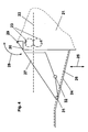
- Fig. 1 shows a schematic sectional view of an inventive device. Specifically shown in Fig. 1 are a deposit tray 1 for a stack 3 formed by sheets 2, and a base frame 4 of the device. Deposit tray 1 can be raised and lowered on base frame 4 in the direction of double arrow 5.
- Sheets 2 are fed to the device along a not specifically illustrated transport path in the direction of arrow 6.
- the device can be mounted or docked to a printing machine on the delivery side.
- the deposit surface of deposit tray 1 for stack 3 comprises, viewed in transport direction 6, essentially three successive zones or sections.
- Section 7 is a front and lowest section of the deposit surface which faces arriving sheets 2 and which extends approximately horizontally, and which extends, in transport direction 6 of sheets 2, for example, approximately 10 millimeters to 30 millimeters, preferably approximately 20 millimeters.
- a first angled section 8 having a relatively steeply rising setting angle ⁇ , which, for example may be approximately 15° to approximately 30°, preferably approximately 22°.
- a relatively flatly rising second angled section 9 having a setting angle ( ⁇ ), which may be, for example, approximately 4° to approximately 12°, preferably approximately 8°.
- Transport rollers 10 which may form the end of a transport path, already feed the respective sheet 2 to stack 3 - which is essentially positioned on section 8 of the deposit surface of deposit tray 1 - at a setting angle or angle of orientation ⁇ , which preferably is dimensioned smaller or equal to setting angle ⁇ of section 8 of deposit tray 1 itself and which, for example, maybe approximately 10° to 20°, preferably approximately 15°.
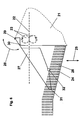
- Fig. 2 shows the device of Fig.1 , again in a perspective view.
- the same component elements have the same reference numbers as in Fig. 1 .
- Fig. 1 illustrates, in particular, that the deposit surface consisting of sections 7, 8, 9 is limited by frame elements 11, 12, 13, so that the stack - which is not shown in Fig. 2 - is deposited in a type of compartment.
- deposit tray 1 is pivoted out of the horizontal plane about an (imaginary) axis extending in transport direction 6 at an angle ⁇ , which may be approximately 5° to approximately 15°, preferably approximately 9°.
- angle ⁇ which may be approximately 5° to approximately 15°, preferably approximately 9°.
- deposit tray 1 - when viewed from the top - is pivoted about an (imaginary) perpendicular axis with frame element 13 about the same angle ⁇ , away from the (remaining) base frame 4.
- Said corner between frame elements 12, 13, however, has a free space for the corner of stack 2, said space extending along a distance b between said two frame elements.
- frame element 12 itself has (in the region of the boundary or apex between sections 8, 9) a free space ⁇ .
- free spaces ⁇ , b for example, may be configured longer, preferably approximately 50 percent longer than the horizontal section 7 of the deposit surface, viewed in transport direction 6 of sheets 2.
- Deposit tray 1 can be arranged in a not specifically illustrated manner on a lateral element 14 of base frame 4, so that it said deposit tray can be raised and lowered. During this movement, the abutment surface of stack 3 slides along frame element 13, which is configured as the stack wall.
- frame element 13 has, in addition, on its upper end, tabs 15 which act as sliding ramps and are angled slightly toward transport direction.
- the angle with respect to the stack wall may be approximately equal to angle ⁇ .
- Fig. 3 shows an exploded view of deposit tray 1 and frame element 13 configured as the stack wall.
- deposit tray 1 has, on its front side facing frame element 13, teeth 16, which act as abutments and spacers relative to frame element 13 in order to permit an air exchange through the gaps between teeth 16, which, however, can also mesh with raised ribs 17 on frame element 13 that support sliding strips 18 in order to improve the sliding motion of the stack abutment surface.
- Fig. 4 shows a side elevation of an inventive device comprising a stacking tray in a first position.
- the device is arranged on the stacker side of a printing machine body 21, of which only a small section is shown schematically.
- a sheet 22 is indicated as it is transported by contradirectionally rotating stiffening rollers 23 in the direction of a stacking tray 24.
- the stacking tray 24 can be moved up and down in the direction of a double arrow 25.
- the stacking tray is brought to a level at which the processed sheet 22 must drop a certain distance to the level of the stacking tray 24, as soon as said sheet is released by the stiffening rollers 23.
- the stacking tray 24 is continuously lowered correspondingly in order to maintain a constant distance between the level of the stiffening rollers 23 and the top side of the stack.
- the stacking tray 24 is angled and has an inclined section, so that the sheets deposited on the stacking tray 24 slide in the direction of the printing machine body 21 and come to a stop.
- An abutment edge for the sheets 2 could also be provided on the free end of the stacking tray 24, where the lead edge of the sheets comes into abutment first.
- a stacking tray 24, as shown by the drawing, is preferably used for printed test sheets. However, in conjunction with the invention, also differently configured stacking surfaces can be used, in particular, for depositing runs of printing sheets.
- Fig. 4 shows a sheet 26 deposited on the stacking tray 24, i.e., for the sake of clarity, only one sheet 26.
- Fig. 4 shows the stacking tray 24 just in a position, in which the guide surfaces 27 still rest on the stacking tray 24 but are already touching down on an edge 30 of the printing machine body 21 at the end of their pivoting movement.
- the guide surfaces 27 contact the stacking tray 24 in different positions by means of different bearing rollers 31, 32.
- the bearing rollers 31 of the guide surfaces 27 rest on the stacking tray 24.
- Fig. 5 shows the device as in Fig. 4 , with the stacking tray 4 in an even more elevated position than in Fig. 4 .
- the guide surfaces 27 do not yet noticeably rest on the edge 30. Almost all the bearing rollers 31 and 32 of the guide surfaces 27 contact the stacking tray 24. In an even more elevated position, the guide surfaces 27 would contact the stacking tray 24 only with the bearing rollers 32. During the movement of the stacking tray 24 in the direction of the double arrow 25 and the simultaneous pivoting movement of the guide surfaces 27 in the direction of the double arrow 8, the respectively contacting bearing rollers 31, 32 roll off the stacking tray 24.
- a small stack of sheets 26 is symbolically indicated.
- Fig. 6 shows the device as in Fig. 4 , depicting a slightly more lowered position of the stacking tray 24 than is shown in Fig. 4 .
- the stack of sheets 26 is symbolically already slightly larger than in Fig. 5 .
- the guide surfaces 27 rest already noticeably on the edge 30. None of the bearing rollers 31 and 32 of the contact surfaces 27 are in contact with the stacking tray 24 any longer.
- Fig. 7 shows the device as in Fig. 4 , on a reduced scale.
- the guide surfaces 27 have been (manually) pivoted all the way up. In this position, a finished stack can be particularly easily removed from the stacking tray 24. In this elevated position, the guide surfaces 27 can preferably be fixed or locked in place. This may be achieved, for example, in a relatively simple way with spring-biased ball plungers, which, for example, come into engagement with cutouts or holes of the guide surfaces, which, however, can also be easily disengaged against a certain resistance.
- the guide surfaces 27 can preferably be unhinged from their suspension on the hinge axle 29. This could be done in the pivoted open position of Fig. 7 , but also in another position.
- Fig. 8 shows a reduced scale plan view of the device as in Fig. 4 .
- corner reinforcements 33 of the guide surfaces 27 can be recognized. These corner reinforcements 33 are also useful for extended hinging on the hinge axle 29.
- the guide surfaces 27 are adjustable with respect to their distance from each other, preferably by means of a motor, in order to accommodate different widths of sheets 26.
- the adjustment is mirror-symmetrical with respect to the longitudinal axis 34 of the stacking tray 24.
- the distance between the guide surfaces 27, or their respective positions, could be specifically optically detected.
- Figs. 4 through 23 and 25 show that the guide surfaces 27 guide the stack of sheets 26, in particular, in a rear area close to the printing machine body 21, this, of course, being relative with respect to the respective length of the sheet 26. Short formats will be guided along their entire length.
- Figs. 4 through 23 also show that the guide surfaces 27 guide the stack of sheets 26 mainly in an upper region, this, of course, also being relative with respect to the individual stack height. Low stacks are guided along their entire height.
- Figs. 4 through 23 show in particular that a sheet 21 is already guided by the guide surfaces 27 when it is ejected from the stiffening rollers 23, i.e., first said sheet's front area and then continuing toward the back.
- the sheet 21 drops or "flies” in a sort of throw trajectory out of the stiffening rollers 23 and then drops onto the stacked sheets 26.
- the guide surfaces 27 arranged in accordance with the invention the sheet 21 is advantageously guided, deflected and aligned during its entire "fight".
Landscapes
- Engineering & Computer Science (AREA)
- Mechanical Engineering (AREA)
- Pile Receivers (AREA)
Abstract
Description
- The invention relates to a device for depositing sheets in a machine that preferably processes sheets by graphic means, in particular for a printing machine, preferably for an electrophotographically operating machine, comprising at least one deposit tray for depositing and preferably also for stacking processed sheets.
- Document
DE 101 54 743 A1 discloses, among other things, a simple design of a support tray for a stack of sheets, which tray may optionally also be a component of a device of the aforementioned type and be specifically arranged on the delivery side of a printing machine. -
U.S.Patent No. 4,605,211 discloses an automatic sheet processing device having a simple and compact structure, and in which alignment and binding of sheets are ensured with a high reliability. - Considering in particular electrophotographically operating printing machines, sheets of the most diverse kind are to be processed, for example, sheets having a different weight per unit area, different size, different surface finish and the like, specifically, because a particular advantage of electrophotgraphic printing is that printing may be personalized and customized. Therefore, printing jobs may also be carried out which include a great variety of different printing materials. However, at the same time, there is the demand for carrying out such printing jobs more rapidly and more cost-effectively than before.
- Depending on the type of sheets, there may be difficulties regarding precise depositing and stacking of the sheets, which may have an unfavorable effect on the subsequent handling of the stack of sheets, for example, if these sheets will have to be bound, stitched or fed to a so-called finishing step in another way.
- Therefore, the object of the invention is to provide a device or a deposit tray of the aforementioned type, which permits a controlled depositing and stacking of sheets, in particular, at greater sheet-processing speeds, and, preferably, in a cost-effective manner.
- In accordance with the invention, this object is achieved with a device for depositing sheets cooperating with a machine, as defined in
claims - An inventive setting angle can advantageously be adapted, in particular, to the sheet quality and the sheet transport speed, in which case this angle can be adjusted about an axis in longitudinal and/or transverse direction with respect to the sheet transport direction.
- A modification of the invention provides that the deposit surface is aligned at an oblique upward angle relative to the horizontal plane.
- As a result of this, arriving sheets can be intercepted and caught, and stacked in proper alignment. In addition, if necessary or desired, the transport speed of the sheets may be slightly reduced before said sheets are deposited. Preferably, the angle (α) is approximately 15° to approximately 30°, preferably approximately 22°. Even a variability of the angle on demand would be conceivable.
- A modification of the invention provides that the deposit surface is configured at an angle having an angle apex line extending transversely with respect to the sheet transport direction. By using such an angle, it is possible to allow, in particular, large sheet formats. Depositing and stacking in accordance with the invention are particularly advantageous and safe, in particular, also when large sheet formats are concerned, specifically also in the case of relatively low weights per unit area and/or higher transport speeds, namely when, as provided by another modification, the deposit surface initially rises relatively steeply at a first angle (α) in sheet transport direction in a first section and is oriented at a second angle (β) at a relatively flatter angle with respect to the horizontal plane in a second section. Also, this type of deposit tray can be produced in a cost-effective manner, for example, of plastic material.
- In this case, the angle (β) preferably is approximately 4° to approximately 12°, preferably approximately 8°.
- According to the invention the deposit surface is inclined or rotated laterally at an angle relative to a horizontal sheet transport path. In so doing, angle (γ) is approximately 5° to approximately 15°, preferably approximately 9°.
- As a result of this inventive arrangement and configuration, advantageously also in the case of larger sheet formats, lower weights per unit area and/or high transport speeds, a defined and cleanly aligned stacking of sheets is ensured in a simple and cost-effective manner, and any subsequent handling is facilitated. This is true as according to the invention the deposit surface is largely, or at least in sections, provided with a frame in a compartment-like manner, which said frame is essentially configured at a right angle on its side facing the arriving sheets, and when the front side of the thusly created compartment facing the arriving sheets is docked to the machine - with respect to a vertical surface oriented in a direction transverse to the sheet transport direction, when viewed from the top, at approximately the same angle (γ) of approximately 5° to approximately 15°, preferably approximately 9° - so that said compartment can be pivoted with respect to the vertical surface, so as to aid the stacking and aligning of the sheets. As a result of the pivotable arrangement, it becomes possible that a right corner angle can be accommodated in this frame, despite the lateral tilt of the deposit surface, and that no oblique-angled deposit surface is created.
- Still, as a precaution, the frame may have open sections in the corner areas and/or near-corner areas as free space for the corners of the sheets. Likewise, the frame could be open laterally in the regions of the angle apex line to create free space for the sheets. Thus, a drawer-like closed frame is not necessary, but the frame can be reduced to guiding and abutment surfaces for the sheets.
- A further modification of the invention provides that, facing the arriving sheets, an approximately horizontal section is provided as the first and deepest section of the deposit surface. This is particularly useful for sheets having low weight per unit area, in order to hold these sheets firmly on the deposit tray, and to prevent these sheets from slipping into or getting stuck in the gap between the deposit tray and the remainder of the machine. In so doing, the horizontal section may extend approximately 10 millimeters to 30 millimeters, preferably approximately 20 millimeters, viewed in transport direction, this being sufficient for the mentioned purposes.
- The aforementioned openings in the frame creating free spaces for the sheets, when they are moving onto the deposit surface, may preferably be longer, preferably approximately 50 percent longer, than the said horizontal section, viewed in sheet transport direction.
- In accordance with a modification of the inventive device, the stacking of sheets - including a stacking height control - is facilitated in that the deposit tray is arranged such that it can be raised and lowered. To achieve this, the deposit tray or the stack formed on the deposit tray may be guided along a guide, in which case, to achieve guiding, the deposit tray and/or the guide may comprise tooth or gear means. Preferably, the guide has sliding surfaces having a relatively low coefficient of friction for the sheets and relative to the sheets, in order to ensure an unimpaired and proper stacking and subsequent descending of the sheets. For example, the deposit tray may be raised or lowered at a rate of 10 millimeters per second. In so doing, the teeth may create a form-closed guide, and may also leave open gaps through which an air exchange is possible in order to avoid air cushions, which could impair the movement of the deposit tray due to said tray's air resistance.
- A further modification of the invention provides that, upstream of the deposit tray, viewed in sheet transport direction, at least one transport element is provided which releases the respective sheet oriented such that it points diagonally upward with respect to the horizontal plane and transfers said sheet onto the deposit tray. Therefore, advantageously, the sheet is released already before or during the transfer to the deposit tray at an approximately appropriate setting angle, which the sheet will assume in the first section of the deposit tray. Preferably, this setting angle or angle of orientation (δ) is dimensioned smaller or equal to the oblique angle (α) of the deposit tray itself. Preferably, the angle of orientation (δ) is preferably approximately 10° to 20°, preferably approximately 15°.
- A preferred embodiment of the inventive machine provides that a vertical dropping distance, or a step, down to the deposit surface is provided for the arriving sheets. This ensures clean stacking; thus, each subsequent sheet is completely dropped on the existing stack, without having said sheet rub across the stack and, in so doing, potentially shift the uppermost sheet on the stack of sheets. Thus, the dropping distance, or the step, may preferably exhibit a perpendicularly measured level difference of approximately 30 millimeters to approximately 40 millimeters, preferably approximately 35 millimeters. In order to control or adjust the level difference, for example, using a tolerance of approximately 5 millimeters, an additional sensor device may be provided. The height of the stack itself may be 200 millimeters, for example.
- Preferably, the deposit surface of the deposit tray is aligned at an oblique upward angle relative to the horizontal plane, in which case, preferably, the deposit surface is configured at an angle having an angle apex line extending in a direction transverse to the sheet transport direction, in that, preferably, the deposit surface initially rises relatively steeply at a first angle (α) in sheet transport direction in a first section and is
- With regard to the formation of a stack, in particular in a commercial printing machine, where a stack is optionally to be transferred for continued processing by binding, stapling, folding or the like, it should be possible to achieve a stack edge alignment whereby the lateral position of the stacked sheets varies only by a maximum of approximately +/- 15 millimeters. In particular with long sheets, which must be transported out more rapidly, even a very minimal angular deviation can lead to much larger deviations. Some large deviations are also caused by the fact that the sheets are transported against an abutment edge in order to align the lead edge of the sheets, in which case rebounding causes even more of a lateral deflection.
- A further object of a separate aspect of the invention is to improve a device for depositing sheets for a machine that processes sheets preferably graphically, specifically for a printing machine, preferably for an electrophotographically operating printing machine, said device comprising at least one stacking surface, preferably a stacking tray, for depositing and preferably also for stacking processed sheets, said stacking surface comprising guide surfaces provided on both sides of a stacking area of the sheet or of the stack, in order to ensure an adequate and reliable alignment of the sheets, in particular, also in view of high depositing rates and/or high stacks and/or long sheet formats.
- In accordance with the invention, this object is achieved in that the guide surfaces are suspended above the stacking surface.
- As a result of this, the inventive device advantageously provides that each sheet to be deposited and the substantial part of a stack are guided reliably and accurately, irrespective of the height of this stack, the speed with which the sheet is deposited or the length of the sheet.
- In particular, the inventive device may comprise a stacking tray, especially the aforementioned tray, which can be lowered and perfectly interacts with the suspended guide surfaces.
- A device of the aforementioned type is known from
US 6 505 830 B2 . With this device, guide surfaces extend through a stacking tray in order to laterally guide and align a stack of sheets. To accommodate different sheet widths, guide surfaces of this type are provided at various distances, allowing guide surfaces that are covered by a wider sheet and thus not utilized to be lowered. But, this known device is rather complex regarding its design and not sturdy enough for commercially operated printing machines. In addition, only a relatively low stack can be formed in this manner on the stacking tray, which is stationary in this case. Further, considering relatively high printing and ejection rates, problems may also arise regarding the productivity level of a printing machine, as well as regarding long sheet formats. - It has been found that it is sufficient, in accordance with the invention, to provide the guide surfaces for guiding only an upper region of the stack. Underneath that, a stacking tray can be lowered almost without restriction in order to build an increasingly taller stack. In contrast, prior art only provided for guiding the foot area of the stack, and too large a stack could then slip off-center or even tip over. Furthermore, an additional advantage of the inventive device is that, underneath the guide surfaces, a part of the stack remains visible to an operator, who can thus monitor it. Even a removal of the finished stack is made easier by the inventive device.
- A preferred embodiment of the inventive device provides that the guide surfaces are pivotably suspended so that they can follow the lowerable stacking tray for a certain distance in a downward moving direction; however, it has been found that approximately 40 millimeters are sufficient.
- With the stacking tray raised, the guide surfaces may rest on the stacking tray; for this purpose, the guide surfaces may have bearing rollers in the region of their lower edges. As the stacking tray is being lowered and the stack is growing, the guide surfaces preferably pivot farther down, in which case the bearing rollers roll off the stacking tray until - as the stacking tray is being lowered even further - they finally come off the stacking tray.
- Another modification of the invention provides that the guide surfaces can be pivoted upward. In their upward pivoted position, the guide surfaces can preferably be fixed or locked in place outside their working position. Consequently, in particular, a finished stack can be removed easily from the stacking surface.
- Another modification of the invention provides that the guide surfaces can be unhinged from their suspending means, that they can be unlocked from or with a pivoting axle, or that they can be unhinged. This is another feature that makes removal of the stack easier. Preferably, however, the unhinging feature specifically represents a safety feature in order to avoid injuries to an operator, in particular, to prevent their being pinched between the top side of the stack and the guide surface elements.
- Preferably, the guide surfaces can be unhinged from their suspension in that the stacking tray, in particular the stack on the stacking tray, is raised.
- Another modification of the invention, which, likewise, independently solves the posed problem, is characterized in that the guide surfaces are provided for guiding mainly or only a rear area of a sheet or of a stack.
- Also, in this case, a part of the lower stack remains visible to the operator, and the stack can be removed more easily. Still, advantageously, a substantial area of the respective sheet and the stack are guided, i.e., the rear area. It has been found that specifically the rear area must be guided securely in order to hold the sheet and the stack in alignment and to prevent a lateral swerving or breaking out of a sheet. Even with an impingement of the sheet on a front stack edge, the rebound would mainly lead to a break-out in the rear area of the sheet. Consequently, a genuine "threading" of the sheet and its front area is not at all that important, but rather a lateral holding of the sheet still in its rear area. Therefore, in accordance with the invention, the front area of the sheet initially moves past the guide surfaces until, finally, its rear area remains between the guide surfaces. This results, in particular, even at high depositing rates, in a precise stack alignment and guiding of the respective sheet.
- Another modification of the invention provides that the guide surfaces can be changed with respect to their distance from each other. Preferably, the guide surfaces are arranged in such a manner that they adjust themselves by opposing mirror-symmetrical movements symmetrically with respect to the central axis of the sheet or of the stack. As a result of this, the inventive device can be adapted to changed sheet widths, in which case the sheet is preferably automatically centered.
- The guide surfaces may be adjusted by means of a motor.
- Also, a device for the detection of the inside distance between the guide surfaces may be provided.
- In combination with the two aforementioned inventive measures, it is possible to additionally advantageously provide a controlling means for the automatic adjustment of the distance between the guide surfaces, in case the detected width deviates from the expected sheet width.
- The schematic drawings show an embodiment of the inventive device without, however, restricting the scope of the invention thereto.
- They show in
- Fig. 1
- a schematic sectional view of an inventive device;
- Fig. 2
- a schematic perspective view of the device as in
Fig. 1 ; - Fig. 3
- a schematic perspective view of a deposit tray for a device as in
Fig. 2 , in an exploded view, relative to a guide or stack wall; - Fig. 4
- a side elevation of an inventive device comprising a stacking tray in a first position;
- Fig. 5
- the device as in
Fig. 4 , with the stacking tray in a more elevated position; - Fig. 6
- the device as in
Fig. 4 , with the stacking tray in a more lowered position; - Fig. 7
- the device as in
Fig. 4 with the guide pivoted up; and - Fig. 8
- the device as in
Fig. 1 , in plan view. -
Fig. 1 shows a schematic sectional view of an inventive device. Specifically shown inFig. 1 are adeposit tray 1 for astack 3 formed by sheets 2, and abase frame 4 of the device.Deposit tray 1 can be raised and lowered onbase frame 4 in the direction ofdouble arrow 5. - Sheets 2 are fed to the device along a not specifically illustrated transport path in the direction of
arrow 6. For example, the device can be mounted or docked to a printing machine on the delivery side. - The deposit surface of
deposit tray 1 forstack 3 comprises, viewed intransport direction 6, essentially three successive zones or sections.Section 7 is a front and lowest section of the deposit surface which faces arriving sheets 2 and which extends approximately horizontally, and which extends, intransport direction 6 of sheets 2, for example, approximately 10 millimeters to 30 millimeters, preferably approximately 20 millimeters. This is followed by a firstangled section 8 having a relatively steeply rising setting angle α, which, for example may be approximately 15° to approximately 30°, preferably approximately 22°. This is followed by a relatively flatly rising secondangled section 9 having a setting angle (β), which may be, for example, approximately 4° to approximately 12°, preferably approximately 8°. -
Transport rollers 10, which may form the end of a transport path, already feed the respective sheet 2 to stack 3 - which is essentially positioned onsection 8 of the deposit surface of deposit tray 1 - at a setting angle or angle of orientation δ, which preferably is dimensioned smaller or equal to setting angle α ofsection 8 ofdeposit tray 1 itself and which, for example, maybe approximately 10° to 20°, preferably approximately 15°. -
Fig. 2 shows the device ofFig.1 , again in a perspective view. The same component elements have the same reference numbers as inFig. 1 . -
Fig. 1 illustrates, in particular, that the deposit surface consisting ofsections frame elements Fig. 2 - is deposited in a type of compartment. In addition, it can be seen thatdeposit tray 1 is pivoted out of the horizontal plane about an (imaginary) axis extending intransport direction 6 at an angle γ, which may be approximately 5° to approximately 15°, preferably approximately 9°. As a result of this, the deposited stack 2 slides into the corner formed byframe elements frame element 13 about the same angle γ, away from the (remaining)base frame 4. Said corner betweenframe elements frame element 12 itself has (in the region of the boundary or apex betweensections 8, 9) a free space α. In so doing, free spaces α, b, for example, may be configured longer, preferably approximately 50 percent longer than thehorizontal section 7 of the deposit surface, viewed intransport direction 6 of sheets 2. -
Deposit tray 1 can be arranged in a not specifically illustrated manner on alateral element 14 ofbase frame 4, so that it said deposit tray can be raised and lowered. During this movement, the abutment surface ofstack 3 slides alongframe element 13, which is configured as the stack wall. For the unimpaired transfer of sheets to deposittray 1,frame element 13 has, in addition, on its upper end,tabs 15 which act as sliding ramps and are angled slightly toward transport direction. Here, the angle with respect to the stack wall may be approximately equal to angle γ. -
Fig. 3 shows an exploded view ofdeposit tray 1 andframe element 13 configured as the stack wall. - This drawing shows that
deposit tray 1 has, on its front side facingframe element 13,teeth 16, which act as abutments and spacers relative to frameelement 13 in order to permit an air exchange through the gaps betweenteeth 16, which, however, can also mesh with raisedribs 17 onframe element 13 that support slidingstrips 18 in order to improve the sliding motion of the stack abutment surface. -
Fig. 4 shows a side elevation of an inventive device comprising a stacking tray in a first position. - The device is arranged on the stacker side of a
printing machine body 21, of which only a small section is shown schematically. In the drawing ofFig. 4 , asheet 22 is indicated as it is transported by contradirectionally rotatingstiffening rollers 23 in the direction of a stackingtray 24. The stackingtray 24 can be moved up and down in the direction of adouble arrow 25. The stacking tray is brought to a level at which the processedsheet 22 must drop a certain distance to the level of the stackingtray 24, as soon as said sheet is released by the stiffeningrollers 23. As the stack ofsheets 26 grows on the stackingtray 24, the stackingtray 24 is continuously lowered correspondingly in order to maintain a constant distance between the level of the stiffeningrollers 23 and the top side of the stack. The stackingtray 24 is angled and has an inclined section, so that the sheets deposited on the stackingtray 24 slide in the direction of theprinting machine body 21 and come to a stop. An abutment edge for the sheets 2 could also be provided on the free end of the stackingtray 24, where the lead edge of the sheets comes into abutment first. A stackingtray 24, as shown by the drawing, is preferably used for printed test sheets. However, in conjunction with the invention, also differently configured stacking surfaces can be used, in particular, for depositing runs of printing sheets.
Fig. 4 shows asheet 26 deposited on the stackingtray 24, i.e., for the sake of clarity, only onesheet 26. Corresponding to the already relatively far lowered position of the stackingtray 24, normally an already larger stack ofsheets 26 would have formed on the stackingtray 24. Thesheet 26 is guided and aligned on both sides byguide surfaces 27, only one of said guide surfaces 27 being shown, of course, in side elevation. The guide surfaces 27 are pivotable along adouble arrow 28 about ahinge axle 29 and are suspended therefrom. -
Fig. 4 shows the stackingtray 24 just in a position, in which the guide surfaces 27 still rest on the stackingtray 24 but are already touching down on anedge 30 of theprinting machine body 21 at the end of their pivoting movement. The guide surfaces 27 contact the stackingtray 24 in different positions by means ofdifferent bearing rollers Fig. 4 , the bearingrollers 31 of the guide surfaces 27 rest on the stackingtray 24. - In the remaining figures, the same reference numbers are used as in
Fig. 4 . -
Fig. 5 shows the device as inFig. 4 , with the stackingtray 4 in an even more elevated position than inFig. 4 . - In this position, the guide surfaces 27 do not yet noticeably rest on the
edge 30. Almost all the bearingrollers tray 24. In an even more elevated position, the guide surfaces 27 would contact the stackingtray 24 only with the bearingrollers 32. During the movement of the stackingtray 24 in the direction of thedouble arrow 25 and the simultaneous pivoting movement of the guide surfaces 27 in the direction of thedouble arrow 8, the respectively contactingbearing rollers tray 24. - In
Fig. 6 , a small stack ofsheets 26 is symbolically indicated. -
Fig. 6 shows the device as inFig. 4 , depicting a slightly more lowered position of the stackingtray 24 than is shown inFig. 4 . The stack ofsheets 26 is symbolically already slightly larger than inFig. 5 .
In this position, the guide surfaces 27 rest already noticeably on theedge 30. None of the bearingrollers tray 24 any longer. -
Fig. 7 shows the device as inFig. 4 , on a reduced scale. In this illustration, the guide surfaces 27 have been (manually) pivoted all the way up. In this position, a finished stack can be particularly easily removed from the stackingtray 24. In this elevated position, the guide surfaces 27 can preferably be fixed or locked in place. This may be achieved, for example, in a relatively simple way with spring-biased ball plungers, which, for example, come into engagement with cutouts or holes of the guide surfaces, which, however, can also be easily disengaged against a certain resistance. - The guide surfaces 27 can preferably be unhinged from their suspension on the
hinge axle 29. This could be done in the pivoted open position ofFig. 7 , but also in another position. - In particular, this could also be useful regarding the work safety of the device.
- If, for example, a stacking
tray 24 fully loaded with a high stack ofsheets 26 is moved up accidentally, the guide surfaces 27 too can be raised or ultimately even completely disengaged automatically. As a result of this, for example, an operator's hands cannot become pinched between the stack surface and the guide surfaces 27. -
Fig. 8 shows a reduced scale plan view of the device as inFig. 4 . - In this illustration,
additional corner reinforcements 33 of the guide surfaces 27 can be recognized. Thesecorner reinforcements 33 are also useful for extended hinging on thehinge axle 29. - The guide surfaces 27 are adjustable with respect to their distance from each other, preferably by means of a motor, in order to accommodate different widths of
sheets 26. The adjustment is mirror-symmetrical with respect to thelongitudinal axis 34 of the stackingtray 24. The distance between the guide surfaces 27, or their respective positions, could be specifically optically detected. -
Figs. 4 through 23 and 25 show that the guide surfaces 27 guide the stack ofsheets 26, in particular, in a rear area close to theprinting machine body 21, this, of course, being relative with respect to the respective length of thesheet 26. Short formats will be guided along their entire length. -
Figs. 4 through 23 also show that the guide surfaces 27 guide the stack ofsheets 26 mainly in an upper region, this, of course, also being relative with respect to the individual stack height. Low stacks are guided along their entire height. - Also,
Figs. 4 through 23 show in particular that asheet 21 is already guided by the guide surfaces 27 when it is ejected from the stiffeningrollers 23, i.e., first said sheet's front area and then continuing toward the back. In the case of high depositing rates, thesheet 21 drops or "flies" in a sort of throw trajectory out of the stiffeningrollers 23 and then drops onto thestacked sheets 26. As a result of the guide surfaces 27 arranged in accordance with the invention, thesheet 21 is advantageously guided, deflected and aligned during its entire "fight".
Claims (13)
- Device for depositing sheets (2) in a machine that processes sheets preferably by graphic means, in particular for a printing machine, preferably for an electrophotographically operating machine, said machine comprising a vertical surface oriented in a direction transverse to a sheet transport direction (6), said device comprising a base frame (4) and at least one deposit tray (1) for depositing and preferably also for stacking processed sheets (2) where a deposit surface consisting of sections (7, 8, 9) of the deposit tray (1) is arranged, or can be arranged, at a first angle (α, β) that deviates in the sheet transport direction (6) from the horizontal plane and the deposit surface is inclined or rotated laterally with respect to the sheet transport path (6) at a second angle (γ) relative to the horizontal plane, characterized in that the deposit surface is largely, or at least in sections, provided with a frame in a compartment-like manner, wherein said frame comprises a first (11), a second (12) and a third (13) frame elements, the first frame element (11) being arranged at the downstream side, the second frame element (12) at the lateral side, and the third frame element at the upstream side with respect to the sheet transport direction (6) to create the compartment, wherein said frame is essentially configured at a right angle on its side facing the arriving sheets, and that the upstream side of the thusly created compartment facing the arriving sheets (2) is dockable to the machine in a pivoted manner with respect to the vertical surface at a third angle approximately the same as the second angle (γ) of approximately 5° to approximately 15°, preferably approximately 9° so that said compartment can be pivoted with respect to the vertical surface, so as to aid the stacking and aligning of the sheets.
- Device as in Claim 1, characterized in that the second (12) and third (13) frame elements have open sections in the corner areas and/or nearcorner areas as free space for the corners of the sheets.
- Device as in one of the previous Claims, characterized in that, in the transport direction (6), the deposit surface is aligned at an oblique upward angle relative to the horizontal plane.
- Device as in Claim 3, characterized in that the sections of the deposit surface comprise a first (8) and second section (9), wherein the first angle (α,β) comprises an angle α and an angle β, the deposit surface initially rises relatively steeply at the angle α in the sheet transport direction (6) in the first section (8) and is oriented at the angle β at a relatively flatter angle with respect to the horizontal plane in the second section (9).
- Device as in Claim 4, characterized in that the second frame element (12) is open laterally in the region of the boundary between the first section (8) and the second section (9) of the deposit surface to create a free space for the sheets.
- Device as in Claim 4, characterized in that the sections of the deposit surface comprise a third section, facing the arriving sheets (2), the approximately horizontal third section is provided as the first and deepest section (7) of the deposit surface.
- Device as in one of the previous Claims, characterized in that the deposit tray (1) is arranged such that it can be raised and lowered.
- Device as in Claim 7, characterized in that the deposit tray (1) is guided along a guide.
- Device as in Claim 8, characterized in that guides, as teeth (16), are provided on the deposit tray (1).
- Machine comprising a device according to any of claims 1 to 9, characterized in that, upstream of the deposit tray (1), viewed in the sheet transport direction (6), at least one transport element is provided which releases the respective sheet (2) oriented such that it points diagonally upward with respect to the horizontal plane and transfers said sheet (2) onto the deposit tray (1).
- Machine as in Claim 10 and comprising at least the features of claim 7, characterized in that a vertical dropping distance, or a step, down to the deposit surface (7, 8, 9) is provided for the arriving sheets (2).
- Machine as in Claim 11, characterized in that the dropping distance, or the step, exhibits a perpendicularly measured level difference of approximately 30 millimeters to approximately 40 millimeters, preferably approximately 35 millimeters.
- Machine as in Claim 12, characterized in that, to control or adjust the level difference, a sensor device is provided.
Applications Claiming Priority (2)
| Application Number | Priority Date | Filing Date | Title |
|---|---|---|---|
| DE102005055890A DE102005055890B4 (en) | 2005-11-22 | 2005-11-22 | Device with guide surfaces for storing sheets for a printing press |
| PCT/EP2006/006219 WO2007059811A2 (en) | 2005-11-22 | 2006-06-27 | Device and tray for depositing sheets |
Publications (2)
| Publication Number | Publication Date |
|---|---|
| EP1954616A2 EP1954616A2 (en) | 2008-08-13 |
| EP1954616B1 true EP1954616B1 (en) | 2012-08-08 |
Family
ID=37057395
Family Applications (1)
| Application Number | Title | Priority Date | Filing Date |
|---|---|---|---|
| EP06762221A Not-in-force EP1954616B1 (en) | 2005-11-22 | 2006-06-27 | Device for depositing sheets |
Country Status (5)
| Country | Link |
|---|---|
| US (1) | US7850167B2 (en) |
| EP (1) | EP1954616B1 (en) |
| JP (1) | JP4920695B2 (en) |
| DE (1) | DE102005055890B4 (en) |
| WO (1) | WO2007059811A2 (en) |
Families Citing this family (5)
| Publication number | Priority date | Publication date | Assignee | Title |
|---|---|---|---|---|
| JP4818133B2 (en) * | 2007-01-17 | 2011-11-16 | ニスカ株式会社 | Printing device |
| DE102009031117B3 (en) * | 2009-06-30 | 2011-02-10 | Eastman Kodak Company | Apparatus and method for the stacked storage of sheet-shaped substrates |
| US20120205862A1 (en) * | 2009-06-30 | 2012-08-16 | Soenke Christian Bluethgen | Device and method for depositing sheet-shaped substrates so as to form a stack |
| JP5780056B2 (en) * | 2011-08-26 | 2015-09-16 | コニカミノルタ株式会社 | Sheet stacking apparatus, document conveying apparatus, image reading apparatus, and image forming apparatus |
| JP7367364B2 (en) * | 2019-07-22 | 2023-10-24 | セイコーエプソン株式会社 | media loading device |
Family Cites Families (21)
| Publication number | Priority date | Publication date | Assignee | Title |
|---|---|---|---|---|
| US3957264A (en) * | 1975-08-07 | 1976-05-18 | International Business Machines Corporation | Collator bins |
| US4265444A (en) * | 1979-09-04 | 1981-05-05 | Minnesota Mining And Manufacturing Company | Paper sheet stacker |
| JPS58202248A (en) * | 1982-05-20 | 1983-11-25 | Fuji Xerox Co Ltd | Freely attachable/detachable sheet discharge tray of copying machine |
| JPS6019642A (en) * | 1983-07-12 | 1985-01-31 | Canon Inc | Sheet collection tray device |
| US4605211A (en) | 1983-07-12 | 1986-08-12 | Canon Kabushiki Kaisha | Automatic sheet processing device having tiltable collecting tray adjacent corner binder station |
| US5215300A (en) * | 1985-03-15 | 1993-06-01 | Canon Kabushiki Kaisha | Tray apparatus |
| JPS61217462A (en) * | 1985-03-20 | 1986-09-27 | Canon Inc | tray device |
| JPS6246862A (en) * | 1985-08-23 | 1987-02-28 | Canon Inc | Sorting/stacking device for sheet material |
| KR880002054A (en) * | 1986-07-28 | 1988-04-28 | 이석형 | Copy paper sorting device |
| JPH03118968A (en) * | 1989-10-02 | 1991-05-21 | Nkk Corp | Test piece cutting device |
| US5374051A (en) * | 1993-04-21 | 1994-12-20 | Xerox Corporation | Relief device for offset stacker tamping mechanism |
| US5497984A (en) * | 1993-07-16 | 1996-03-12 | Sharp Kabushiki Kaisha | Sheet post-processing apparatus |
| JPH10203687A (en) * | 1997-01-17 | 1998-08-04 | Mita Ind Co Ltd | Circulative type document conveyer |
| KR100480463B1 (en) * | 1998-09-17 | 2005-09-12 | 주식회사신도리코 | Paper finishing device |
| JP2001341927A (en) * | 2000-06-05 | 2001-12-11 | Ricoh Co Ltd | Sheet media processing equipment |
| DE10043392A1 (en) * | 2000-09-04 | 2002-03-14 | Heidelberger Druckmasch Ag | Arrangement for stacked storage and alignment of sheet material is separately replaceable unit for manually fitting to output station and manual set up for several formats |
| JP3973836B2 (en) * | 2000-12-15 | 2007-09-12 | 株式会社リコー | Sheet-like medium processing apparatus, image forming apparatus, and sheet-like medium post-processing apparatus |
| JP3675723B2 (en) * | 2001-02-19 | 2005-07-27 | ニスカ株式会社 | Sheet discharging apparatus and image forming apparatus provided with the apparatus |
| US6467769B2 (en) * | 2001-03-22 | 2002-10-22 | Hewlett-Packard Co. | Output bin for printing devices |
| US6832759B2 (en) * | 2001-03-30 | 2004-12-21 | Ricoh Company, Ltd. | Sheet-shaped medium aligning apparatus, image forming apparatus, and sheet-shaped medium after-treatment apparatus |
| DE10154743A1 (en) | 2001-11-09 | 2003-05-22 | Nexpress Solutions Llc | Paper trolley |
-
2005
- 2005-11-22 DE DE102005055890A patent/DE102005055890B4/en not_active Expired - Fee Related
-
2006
- 2006-06-27 EP EP06762221A patent/EP1954616B1/en not_active Not-in-force
- 2006-06-27 JP JP2008540466A patent/JP4920695B2/en not_active Expired - Fee Related
- 2006-06-27 WO PCT/EP2006/006219 patent/WO2007059811A2/en not_active Ceased
- 2006-06-27 US US12/094,289 patent/US7850167B2/en not_active Expired - Fee Related
Also Published As
| Publication number | Publication date |
|---|---|
| US7850167B2 (en) | 2010-12-14 |
| WO2007059811A2 (en) | 2007-05-31 |
| JP2009521376A (en) | 2009-06-04 |
| JP4920695B2 (en) | 2012-04-18 |
| EP1954616A2 (en) | 2008-08-13 |
| DE102005055890B4 (en) | 2013-03-28 |
| DE102005055890A1 (en) | 2007-05-24 |
| WO2007059811A3 (en) | 2010-05-14 |
| US20080230983A1 (en) | 2008-09-25 |
Similar Documents
| Publication | Publication Date | Title |
|---|---|---|
| US6450934B1 (en) | High speed post processing machine | |
| EP1862416B1 (en) | Bill Processor | |
| EP0490272A1 (en) | Guiding device for stacking sheets of paper | |
| CN103974885B (en) | For piling apparatus and the mail machine of the flat article of edge-on accumulation | |
| KR100503595B1 (en) | Sheet aligning apparatus | |
| US4890825A (en) | Paper sheet stacking and jogging apparatus | |
| US7850167B2 (en) | Device and tray for depositing sheets | |
| JP7788086B2 (en) | Sheet stacking device and image forming system | |
| JP6410324B2 (en) | Sheet stacking device | |
| JP2009524533A (en) | Device for collating flat objects and for further conveying collated objects | |
| US6685181B2 (en) | Paper dispensing mechanism | |
| JPS62215464A (en) | Sheet assorting device | |
| US20060267264A1 (en) | Sheet feed apparatus | |
| CA2181966A1 (en) | Apparatus for delivering printed products to a further-processing location | |
| US20020060412A1 (en) | Sheet understacking feeding mechanism | |
| CN101295154B (en) | Paper discharge device, image forming device, and paper discharge method | |
| JP2007145582A (en) | Media separation and removal mechanism | |
| US9394122B2 (en) | Feeder for flat objects, particularly supplement feeder | |
| JPH11513957A (en) | Paper set supply | |
| JP2004538225A (en) | Apparatus and method for aligning a stack of sequentially stacked sheets | |
| JP2018024505A (en) | Paper alignment mechanism | |
| US5695181A (en) | Sheet sorting apparatus | |
| JP6831196B2 (en) | Sheet stacking device | |
| US4164348A (en) | Jogging apparatus | |
| WO2001000517A1 (en) | Bail assembly |
Legal Events
| Date | Code | Title | Description |
|---|---|---|---|
| PUAI | Public reference made under article 153(3) epc to a published international application that has entered the european phase |
Free format text: ORIGINAL CODE: 0009012 |
|
| 17P | Request for examination filed |
Effective date: 20080328 |
|
| AK | Designated contracting states |
Kind code of ref document: A2 Designated state(s): AT BE BG CH CY CZ DE DK EE ES FI FR GB GR HU IE IS IT LI LT LU LV MC NL PL PT RO SE SI SK TR |
|
| AX | Request for extension of the european patent |
Extension state: AL BA HR MK RS |
|
| R17D | Deferred search report published (corrected) |
Effective date: 20100514 |
|
| REG | Reference to a national code |
Ref country code: DE Ref legal event code: 8566 |
|
| 17Q | First examination report despatched |
Effective date: 20101221 |
|
| DAX | Request for extension of the european patent (deleted) | ||
| RBV | Designated contracting states (corrected) |
Designated state(s): FR GB NL |
|
| RTI1 | Title (correction) |
Free format text: DEVICE FOR DEPOSITING SHEETS |
|
| GRAP | Despatch of communication of intention to grant a patent |
Free format text: ORIGINAL CODE: EPIDOSNIGR1 |
|
| GRAS | Grant fee paid |
Free format text: ORIGINAL CODE: EPIDOSNIGR3 |
|
| GRAA | (expected) grant |
Free format text: ORIGINAL CODE: 0009210 |
|
| AK | Designated contracting states |
Kind code of ref document: B1 Designated state(s): FR GB NL |
|
| REG | Reference to a national code |
Ref country code: GB Ref legal event code: FG4D |
|
| REG | Reference to a national code |
Ref country code: NL Ref legal event code: T3 |
|
| PLBE | No opposition filed within time limit |
Free format text: ORIGINAL CODE: 0009261 |
|
| STAA | Information on the status of an ep patent application or granted ep patent |
Free format text: STATUS: NO OPPOSITION FILED WITHIN TIME LIMIT |
|
| 26N | No opposition filed |
Effective date: 20130510 |
|
| PGFP | Annual fee paid to national office [announced via postgrant information from national office to epo] |
Ref country code: GB Payment date: 20130529 Year of fee payment: 8 |
|
| REG | Reference to a national code |
Ref country code: FR Ref legal event code: ST Effective date: 20140228 |
|
| PG25 | Lapsed in a contracting state [announced via postgrant information from national office to epo] |
Ref country code: FR Free format text: LAPSE BECAUSE OF NON-PAYMENT OF DUE FEES Effective date: 20130701 |
|
| GBPC | Gb: european patent ceased through non-payment of renewal fee |
Effective date: 20140627 |
|
| PG25 | Lapsed in a contracting state [announced via postgrant information from national office to epo] |
Ref country code: GB Free format text: LAPSE BECAUSE OF NON-PAYMENT OF DUE FEES Effective date: 20140627 |
|
| PGFP | Annual fee paid to national office [announced via postgrant information from national office to epo] |
Ref country code: NL Payment date: 20170614 Year of fee payment: 12 |
|
| REG | Reference to a national code |
Ref country code: NL Ref legal event code: MM Effective date: 20180701 |
|
| PG25 | Lapsed in a contracting state [announced via postgrant information from national office to epo] |
Ref country code: NL Free format text: LAPSE BECAUSE OF NON-PAYMENT OF DUE FEES Effective date: 20180701 |