EP1954565B1 - Filling machine - Google Patents
Filling machine Download PDFInfo
- Publication number
- EP1954565B1 EP1954565B1 EP06838425A EP06838425A EP1954565B1 EP 1954565 B1 EP1954565 B1 EP 1954565B1 EP 06838425 A EP06838425 A EP 06838425A EP 06838425 A EP06838425 A EP 06838425A EP 1954565 B1 EP1954565 B1 EP 1954565B1
- Authority
- EP
- European Patent Office
- Prior art keywords
- fill
- filling machine
- assembly
- container
- fill line
- Prior art date
- Legal status (The legal status is an assumption and is not a legal conclusion. Google has not performed a legal analysis and makes no representation as to the accuracy of the status listed.)
- Expired - Fee Related
Links
- 239000012530 fluid Substances 0.000 claims description 84
- 238000007789 sealing Methods 0.000 claims description 26
- 238000004891 communication Methods 0.000 claims description 14
- 239000004033 plastic Substances 0.000 claims description 5
- 229920003023 plastic Polymers 0.000 claims description 5
- 238000010276 construction Methods 0.000 description 23
- 239000000243 solution Substances 0.000 description 18
- 238000000034 method Methods 0.000 description 17
- 238000004140 cleaning Methods 0.000 description 9
- 230000001954 sterilising effect Effects 0.000 description 9
- 238000011109 contamination Methods 0.000 description 7
- 229960000074 biopharmaceutical Drugs 0.000 description 5
- 238000004806 packaging method and process Methods 0.000 description 5
- 238000004659 sterilization and disinfection Methods 0.000 description 5
- 239000000126 substance Substances 0.000 description 5
- 235000013305 food Nutrition 0.000 description 4
- -1 biopharmaceuticals Substances 0.000 description 3
- 230000008878 coupling Effects 0.000 description 3
- 238000010168 coupling process Methods 0.000 description 3
- 238000005859 coupling reaction Methods 0.000 description 3
- 230000036512 infertility Effects 0.000 description 3
- 238000009434 installation Methods 0.000 description 3
- 239000000463 material Substances 0.000 description 3
- 238000012360 testing method Methods 0.000 description 3
- 229920001169 thermoplastic Polymers 0.000 description 3
- 239000004416 thermosoftening plastic Substances 0.000 description 3
- IJGRMHOSHXDMSA-UHFFFAOYSA-N Atomic nitrogen Chemical compound N#N IJGRMHOSHXDMSA-UHFFFAOYSA-N 0.000 description 2
- 230000000712 assembly Effects 0.000 description 2
- 238000000429 assembly Methods 0.000 description 2
- 238000003780 insertion Methods 0.000 description 2
- 230000037431 insertion Effects 0.000 description 2
- 238000004519 manufacturing process Methods 0.000 description 2
- 238000003860 storage Methods 0.000 description 2
- 229920002725 thermoplastic elastomer Polymers 0.000 description 2
- 238000012546 transfer Methods 0.000 description 2
- 238000010200 validation analysis Methods 0.000 description 2
- 239000004677 Nylon Substances 0.000 description 1
- 239000004698 Polyethylene Substances 0.000 description 1
- 239000004743 Polypropylene Substances 0.000 description 1
- 238000013459 approach Methods 0.000 description 1
- 238000010364 biochemical engineering Methods 0.000 description 1
- 239000000356 contaminant Substances 0.000 description 1
- 238000012864 cross contamination Methods 0.000 description 1
- 230000001419 dependent effect Effects 0.000 description 1
- 239000003814 drug Substances 0.000 description 1
- 238000005516 engineering process Methods 0.000 description 1
- 230000005284 excitation Effects 0.000 description 1
- 239000007789 gas Substances 0.000 description 1
- 239000001307 helium Substances 0.000 description 1
- 229910052734 helium Inorganic materials 0.000 description 1
- SWQJXJOGLNCZEY-UHFFFAOYSA-N helium atom Chemical compound [He] SWQJXJOGLNCZEY-UHFFFAOYSA-N 0.000 description 1
- 238000011900 installation process Methods 0.000 description 1
- 238000001990 intravenous administration Methods 0.000 description 1
- 238000002955 isolation Methods 0.000 description 1
- 229910052757 nitrogen Inorganic materials 0.000 description 1
- 229920001778 nylon Polymers 0.000 description 1
- 238000012856 packing Methods 0.000 description 1
- 230000002572 peristaltic effect Effects 0.000 description 1
- 239000003186 pharmaceutical solution Substances 0.000 description 1
- 239000004014 plasticizer Substances 0.000 description 1
- 229920000573 polyethylene Polymers 0.000 description 1
- 229920000642 polymer Polymers 0.000 description 1
- 229920000098 polyolefin Polymers 0.000 description 1
- 229920001155 polypropylene Polymers 0.000 description 1
- 238000012545 processing Methods 0.000 description 1
- 230000001681 protective effect Effects 0.000 description 1
- 238000000275 quality assurance Methods 0.000 description 1
- 238000010025 steaming Methods 0.000 description 1
- 238000012414 sterilization procedure Methods 0.000 description 1
- 231100000331 toxic Toxicity 0.000 description 1
- 230000002588 toxic effect Effects 0.000 description 1
- 238000011144 upstream manufacturing Methods 0.000 description 1
- XLYOFNOQVPJJNP-UHFFFAOYSA-N water Substances O XLYOFNOQVPJJNP-UHFFFAOYSA-N 0.000 description 1
Images


Classifications
-
- B—PERFORMING OPERATIONS; TRANSPORTING
- B65—CONVEYING; PACKING; STORING; HANDLING THIN OR FILAMENTARY MATERIAL
- B65B—MACHINES, APPARATUS OR DEVICES FOR, OR METHODS OF, PACKAGING ARTICLES OR MATERIALS; UNPACKING
- B65B3/00—Packaging plastic material, semiliquids, liquids or mixed solids and liquids, in individual containers or receptacles, e.g. bags, sacks, boxes, cartons, cans, or jars
- B65B3/003—Filling medical containers such as ampoules, vials, syringes or the like
-
- B—PERFORMING OPERATIONS; TRANSPORTING
- B65—CONVEYING; PACKING; STORING; HANDLING THIN OR FILAMENTARY MATERIAL
- B65B—MACHINES, APPARATUS OR DEVICES FOR, OR METHODS OF, PACKAGING ARTICLES OR MATERIALS; UNPACKING
- B65B3/00—Packaging plastic material, semiliquids, liquids or mixed solids and liquids, in individual containers or receptacles, e.g. bags, sacks, boxes, cartons, cans, or jars
- B65B3/26—Methods or devices for controlling the quantity of the material fed or filled
- B65B3/30—Methods or devices for controlling the quantity of the material fed or filled by volumetric measurement
-
- B—PERFORMING OPERATIONS; TRANSPORTING
- B65—CONVEYING; PACKING; STORING; HANDLING THIN OR FILAMENTARY MATERIAL
- B65B—MACHINES, APPARATUS OR DEVICES FOR, OR METHODS OF, PACKAGING ARTICLES OR MATERIALS; UNPACKING
- B65B59/00—Arrangements to enable machines to handle articles of different sizes, to produce packages of different sizes, to vary the contents of packages, to handle different types of packaging material, or to give access for cleaning or maintenance purposes
- B65B59/04—Machines constructed with readily-detachable units or assemblies, e.g. to facilitate maintenance
Definitions
- the present invention relates to filling machines.
- Automated fill systems and filling machines are used for transferring fluids from a reservoir to containers.
- these automated systems incorporate a flow meter to accurately control the amount of fluid introduced into each container, either by mass (weight) or volume.
- the automated systems also generally include a stop valve controlled by the flow meter and a nozzle used to transfer the measured amount of fluid to a container.
- US 5129212 discloses a filling machine according to the preamble of claim 1.
- terminal sterilization it is often desirable to sterilize the container and the fluid after the fluid has been placed into the container. Sterilizing the fluid and container after the fluid is placed into the container is known as terminal sterilization.
- Autoclaving is one method of terminal sterilization. Autoclaving typically includes the use of pressurized steam to sterilize the container and fluid.
- biophannaceuticals are typically not suited for such terminal autoclaving because the pressurized steam, which is often superheated, can destroy living organisms in the biopharmaceutical solution. Therefore, manual methods for terminal sterilization have been developed. Such methods are labor intensive, time consuming, and costly.
- US 2003/0230521 has been interpreted by the European Patent Office as disclosing at least a filling machine operable to dispense a fluid from a fluid supply to a container having an opening and a cap configured to cover the opening, the filling machine comprising: a fill line assembly having an inlet and an outlet, the inlet configured to be coupled to the fluid supply, the outlet configured to be placed in fluid communication with the opening of the container, wherein the fill line assembly is removably coupled to the filling machine, and wherein fluid flowing from the fluid supply to the container flows through the fill line assembly.
- US 2003/ 0230521 has likewise been interpreted by the European Patent Office as disclosing a method of operating a filling machine, the method comprising: inserting a fill conduit of a container; removing the cap from the opening of the fill conduit; dispensing a fluid from a fluid supply into the container; and sealing the fill conduit of the container.
- US patent application publication 2003/0178097 teaches a needle holder for use in a filling machine, the needle holder serving for accommodating a plurality of needles for filling vials, ampoules or the like, and the respective needle having a tubular needle section and a needle attachment which can be connected to a filling tube or the like, and with means for fastening the needles on the needle holder.
- a retaining element and clamping elements are provided.
- the retaining element is provided on one side with a plurality of mutually parallel grooves for accommodating the needle sections of the needles.
- the clamping elements can be connected to the retaining element and are intended for fixing the needles in the grooves.
- the present invention provides a filling machine in accordance with independent claim 1. Preferred embodiments of the invention are reflected in the dependent claims.
- a filling machine is provided and operable to dispense a fluid from a fluid supply to a container having an opening and a cap configured to cover the opening.
- the filling machine includes a housing that defines a fill chamber and a cap removal assembly at least partially located within the fill chamber.
- the cap removal assembly is operable to remove the cap from the opening of the container within the fill chamber.
- the filling machine further includes a fill line assembly having an inlet and an outlet.
- the inlet is configured to be coupled to the fluid supply and the outlet is located within the fill chamber.
- the outlet is configured to be placed in fluid communication to the opening of the container.
- the fill line assembly is removably coupled with the filling machine, and fluid flowing from the fluid supply to the container flows through the fill line assembly.
- the filling machine is operable to dispense a fluid from a fluid supply to a container having a body portion and a fill conduit extending from the body portion.
- the fill conduit defines an opening of the container.
- the filling machine includes a housing that defines a fill chamber and an aperture configured to receive the fill conduit to position at least a portion of the fill conduit within the fill chamber.
- the filling machine further includes a fill line assembly and a conduit sealing assembly operable to seal the fill conduit.
- the fill line assembly includes an inlet and an outlet. The inlet is configured to be coupled to the fluid supply and the outlet is located within the fill chamber. The outlet is configured to be placed in fluid communication with the opening of the container.
- the fill line assembly is removably coupled with the filling machine, and fluid flowing from the fluid supply to the container flows through the fill line assembly.
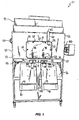
- Fig. 1 is a front view of a filling machine of the present invention.
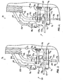
- Fig. 2 is an enlarged view of a filling station of the filling machine of Fig. 1 .
- Fig. 3 is an enlarged rear view of the filling station of Fig. 2 .
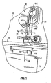
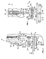
- Fig. 4 is an enlarged front view illustrating a conduit sealing assembly of the filling machine of Fig. 1 .
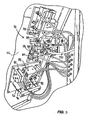
- Fig. 5 is a rear perspective view of the filling machine of Fig. 1 .
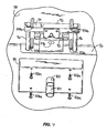
- Fig. 6 is a cross section view of a flow meter and a fill line assembly of the filling machine Fig. 1 .
- Fig. 7 is an enlarged view of the filling station of the filling machine of Fig. 1 .
- Fig. 8 is an enlarged view of a top portion of the flow meter and fill line assembly of the filling machine of Fig. 1 .
- Fig. 9 is an enlarged view of a bottom portion of the flow meter and fill line assembly of the filling machine of Fig. 1 .
- Fig. 10 is an enlarged from view of the filling station of Fig. 1 illustrating containers being inserted into a fill chamber.
- Figs. 11-18 illustrate a method of operating the filling machine of Fig. 1 ; not forming part of this invention.
- Fig. 19 illustrates an alternative construction of the filling machine of Fig. 1 .
- Fig. 1 illustrates a filling machine 51 operable to fill containers, such as thermoplastic bags including, intravenous solution bags (IV bags), pharmaceutical bags, and the like with any suitable fluid such as pharmaceutical solutions, media solutions, biopharmaceuticals, chemicals, foods, etc.
- the filling machine can be utilized to fill other suitable containers.
- the filling machine 51 includes a housing 52 that defines a substantially aseptic fill chamber 53.
- the fill chamber 53 is defined by a front wall 55, a rear wall 56, side walls 57, and a bottom wall 58.
- the illustrated front wall 55 includes a viewing window 59 that includes a plurality of latches 61.
- the latches 61 couple the viewing window 59 to the front wall 55.
- a sensor 63 includes a portion 64 that is coupled to the front wall 55 and a portion 65 that is coupled the viewing window 59. The sensor 63 signals whether the viewing window 59 is in the position as shown in Fig. 1 or if the viewing window 59 has been removed from the front wall 55.
- the illustrated rear wall 56 is located at approximately a 30 degree angle relative to the front wall 55 and slopes from the rear of the filling machine 51 towards the front. In other constructions, the rear wall can be located at any suitable angle relative to the front wall, and in one construction the rear wall is located at approximately 90 degrees relative to the front wall 55.
- a bag support apparatus 70 is coupled to the rear wall 56 outside of the fill chamber 53.
- the illustrated bag support apparatus 70 includes an adjustable bag support 71 and a bag handle support 72.
- An air handling unit 74 is coupled to the top of the filling machine 51 and is in fluid communication with the fill chamber 53.
- the air handling unit 74 includes a fan and an air filter.
- the air filter is a HEPA filter that creates a class 100 environment within the substantially aseptic fill chamber 53.
- the air handling unit 74 is operable to provide an air flow to the fill chamber 53 to maintain the fill chamber 53 under a positive pressure with respect to an atmospheric pressure.
- the air handling unit 74 is configured to achieve laminar flow (i.e. no flow eddies) through the fill chamber 53.
- a pressure measuring device 76 ( Fig. 5 ) is utilized to measure a difference between the fill chamber pressure and the atmospheric pressure.
- a test port 77 ( Fig. 1 ) extends through the bottom wall 58 of the fill chamber 53. The test port 77 can be placed in fluid communication with an air monitor, or other similar device, to test or monitor the air quality within the substantially aseptic fill chamber 53.
- container filling stations 78 are located within the fill chamber 53. While the illustrated filling machine 51 includes two filling stations 78, it should be understood that the filling machine 51 may include any suitable number of filling stations 78. Both of the filling stations 78 are the substantially the same, and therefore only one of the filling stations 78 will be described in detail below.
- the bag filling station 78 includes a corresponding conduit insertion aperture 79a and a cap disposal aperture 79b that extend through the bottom wall 58 of the fill chamber 53.
- a hollow sleeve 80a is aligned with the aperture 79a, and a hollow sleeve 80b is aligned with the aperture 79b.
- the bag filling station 78 includes a tube or fill conduit support clamp 81.
- the tube support clamp 81 includes a tube receiving portion 82 and a sensor 84 located adjacent the tube receiving portion 82.
- Arms 86 extend from the tube receiving portion 82 through openings in the rear wall 56. Seals 90 inhibit fluid communication through the openings between the fill chamber 53 and the exterior atmosphere.
- the arms 86 are coupled to an actuator 88 ( Fig. 3 ) that moves the tube support clamp 81 between an open position ( Fig. 17 ) and a closed position ( Fig. 14 ).
- the actuator 88 is a pneumatic actuator, and in other constructions the actuator can be any suitable actuator, such as an electric actuator and the like.
- a tube or conduit sealing assembly 92 is located outside of the fill chamber 53, beneath the bottom wall 58.
- the sealing assembly 92 can be located within the fill chamber 53, as illustrated in Fig. 19 , generally between the tube support clamp 81 and the bottom wall 58.
- the sealing assembly 92 outside of the fill chamber 53, the number of apertures or openings that extend through exterior walls of the fill chamber 53 to the external environment are reduced.
- the sealing assembly 92 includes a fixed member 93 and a movable member 94.
- the movable member 94 includes two arms 96 that extend through openings in the rear wall 56.
- the two arms 96 are coupled to an actuator 98 ( Fig. 3 ) that moves the sealing assembly 92 between an open position ( Fig. 15 ) and closed position ( Fig. 16 ).
- the sealing assembly 92 is operable to create a radio frequency (RF) seal in a thermoplastic tube.
- RF radio frequency
- the illustrated sealing assembly 92 is a radio frequency sealing assembly, in other constructions other suitable sealing assemblies can be utilized, such as heat sealing assemblies. In yet other constructions, the sealing assembly can be omitted.
- a cover 99 is used to enclose the sealing assembly 92.
- the cover 99 includes hollow sleeves 100 and 101.
- the sleeve 100 is aligned with the aperture 79a ( Fig. 11 ) and the sleeve 101 is aligned with the aperture 79b.
- the cover 99 is coupled to the bottom wall 58 of the fill chamber 53 using screws 102a that are received in corresponding apertures 102b.
- the filling station 78 also includes a fill line bracket 103 that includes a tubular portion 104. A pin 106 is received by apertures 107 in the fill line bracket 103.
- the filing station 78 further includes a cap removal assembly 108.
- the illustrated cap removal assembly 108 includes a cap removal tube 109 that is located adjacent the fill line bracket 103.
- the cap removal tube 109 is a generally hollow member and includes a first portion 111 with a diameter and a second portion 112 with a diameter that is less than the diameter of the first portion 111.
- the cap removal tube 109 is in fluid communication with a vacuum generation device of the cap removal assembly, such that the vacuum generation device is operable to create a vacuum within the cap removal tube 109.
- the cap removal assembly can take other suitable forms.
- the removal assembly is operable to remove a cap that is hingedly coupled to the container (i.e., a flip-open type cap).
- the cap removal assembly can be operable to replace the cap.
- a carrier assembly 116 which is a clamp in the illustrated construction, couples the fill line bracket 103 and the cap removal tube 109, such that the fill line bracket 103 and the cap removal tube 109 move in unison.
- a first actuator 118 and a second actuator 119 are operable to move the carrier 116.
- the first actuator 118 is operable move the carrier 116 in directions parallel to the rear wall 56 and the second actuator 119 is operable to move the carrier 116 in horizontal directions. While the illustrated actuators 118, 119 are air operated or pneumatic actuators, it should be understood that any suitable actuator can be utilized, such as electrically operated actuators.
- the bag filling station 78 further includes a corresponding mass flow meter 121.
- the flow meter 121 includes an enclosed hollow cylinder 122 that defines a centrally located tubular passageway 124 that extends through ends of the cylinder 122.
- the cylinder 122 can contain nitrogen, helium or other gases to facilitate operation of the flow meter 121.
- the flow meter 121 is a Coriolis flow meter such as a Coriolis flow meter available from Micro Motion, Endress + Hauser and others. The operation of a Coriolis flow measuring system is understood to one of ordinary skill in the art and is therefore not presented in detail in this application.
- the filling machine 51 further includes a common disposable fill line assembly 126.
- the fill line assembly 126 is substantially similar to one or more of the embodiments described in U.S. Patent Application Publication No. 2006/0010991, filed July 14, 2005 .
- the disposable fill line assembly 126 includes a solution filter 128, a manifold 130, and fill lines 132.
- the filter 128 defines an inlet 136 of the fill line assembly 126, and the illustrated filter 128 is coupled to a fluid supply 138 such that the inlet 136 of the fill line assembly 126 is in fluid communication with the fluid supply 138.
- the fluid supply 138 can be any suitable source of fluid, which may include biopharmaceuticals, pharmaceuticals, media solutions, other chemicals, foods and the like.
- the source of fluid is at a pressure above atmospheric pressure. In one such method, the pressure is above approximately 8 pounds per square inch (psi). In yet other methods of operating the filling machine 51, the pressure of the fluid is above approximately 8 psi and could be 85 psi or higher.
- the filling machine 51 can be operated with the source of fluid at any suitable pressure.
- the manifold 130 fluidly couples the filter 128 with the fill lines 132. While the illustrated fill line assembly 126 includes two fill lines 132 that correspond with the two container filling stations 78 ( Fig. 1 ), it should be understood that the fill line assembly 126 can include any number of fill lines 132 to correspond to the number of container filling stations 78. Each of the fill lines 132 includes a nozzle 139a that defines an outlet 139b of the fill line assembly 126.
- each fill line 132 further includes a mass flow meter liner portion 140.
- a top liner adapter 142 and a bottom liner adapter 144 fluidly couple the flow meter liner 140 within the fill line 132.
- the mass flow meter liner 140 has a smaller wall thickness and lower durometer value than the other portions of the fill line 132.
- the fill line 132 can be formed from flexible, semi-rigid, or rigid plastic tubing.
- the fill lines 132 can be made of polyethylene, polypropylene, polyolefins, nylon, thermoplastic elastomer, or any combination of these materials. Other formable materials that are resistant to corrosive fluids can also be used.
- the fill line 132 can be irradiated, washed, chemically sterilized, or the like.
- the illustrated fill line 132 includes a cover 146 (see Fig. 7 ) that is placed over the outlet 139b of the fill line assembly 126 after the fill line 132 and fill line assembly 126 are pre-sterilized and before being packaged to maintain sterility.
- the cover 146 substantially prevents contaminants from entering the fill line assembly 126 through the outlet 139b.
- the illustrated fill line 132 is made of commercially available thermoplastic elastomer C-FLEX medical grade tubing available from Consolidated Polymer Technologies, Inc. of Clearwater, FL, however, other suitable tubing, conduit, liner and film materials can also be used.
- C-FLEX tubing is known for its bio-compatibility, temperature stability, moisture stability, sterile compatibility, and is made without toxic plasticizers, making it a good choice for pharmaceutical, chemical, and food packing applications.
- the illustrated filling machine 51 further includes a first pinch valve 148 and a second pinch valve 150 that correspond to one of the filling stations 78.
- the valves 148, 150 are configured to receive the fill line 132 when the fill line assembly 126 is installed into the filling machine 51.
- the illustrated first and second valves 148, 150 are air actuated pinch valves. However, it should be understood that any suitable valve can be utilized, such as butterfly, ball, or diaphragm valves.
- the fill line assembly 126 is first unwrapped from its packaging.
- the packaging is utilized to maintain the sterility of the fill line assembly 126 that can be pre-sterilized as discussed above.
- the solution filter 128 is slid into a filter bracket 154 and the inlet 136 of the fill line assembly 126, which is defined by the filter 128, is coupled to the fluid supply 138.
- the fill line 132 is routed through the flow meter 121.
- the end of the fill line 132 includes the nozzle 139a and the nozzle cover 146 having a lead 158 extending from the nozzle cover 146 ( Fig. 7 ).
- the lead 158 is fed through the mass flow meter 121 from the top to the bottom and after the lead 158 is exposed from the bottom, the fill line 132 is pulled through the mass flow meter 121.
- the fill line 132 can be pulled through the mass flow meter 121 from the bottom of the flow meter 121 to the top of the follow meter 121.
- the fill line 132 is pulled until the mass flow meter liner 140 is positioned within the mass flow meter 121.
- the mass flow meter liner 140 is connected within the fill line 132 through the top and bottom liner adapters 142, 144.
- the liner adapters 142, 144 each include radial alignment marks 168 such that the marks 168 can be aligned with notches 172 on the top and bottom liner holders 174 of the mass flow meter 121 to ensure that the liner 140 is not twisted within the mass flow meter 121.
- the adapters 142, 144 are secured to the holders 174 by sliding retaining clips 178 into the liner holders 174 to clip the liner adapters 142, 144 and liner 140 in place. It may be necessary to use a tie wrap to secure the connection between the fill line 132 and the top and bottom liner adapters 142, 144 so that these components do not disconnect when the fill line 132 is pressurized. Typically, the tie wrap is not pre-assembled because it would be difficult to pass through the constrained spaced within the mass flow meter 121.
- the fill line 132 is routed through an aperture 182 in a panel of the filling machine 51 ( Fig. 5 ).
- the fill line 132 is inserted into the tubular portion 104 of the fill line bracket 103 and carrier assembly 116 until the fill line 132 extends into the fill chamber 53 ( Fig. 7 ).
- the protective viewing window 59 ( Fig. 1 ) is removed by unlocking the latches 61 holding it in place.
- the lead 158 is pulled to draw the fill line 132 and nozzle 139a through the tubular portion 104 ( Fig. 7 ).
- the fill line 132 is routed through the first and second pinch valves 148, 150 at the rear of the filling assembly 51.
- the nozzle 139a that defines the outlet 139b of the fill line assembly 126 is secured within the fill chamber 53 by coupling the nozzle 139a of the fill line 132 to the fill line bracket 103.
- the lead 158 is inserted through the aperture 79a (see Fig. 12 ) at the bottom of the fill chamber 53.
- the nozzle 139a is positioned in the fill line bracket 103, and the pin 106 is then inserted through the aligned apertures 107 to secure the position of the nozzle 139a to the fill line bracket 103 and the carrier assembly 116.
- tie wrap 186 it may be necessary to use a tie wrap 186 to secure the connection between the fill line 132 and the nozzle 139a such that these components do not disconnect when the fill line 132 is pressurized.
- This particular tie wrap 186 is not pre-assembled because it would be difficult to pass through the constrained spaced of the tubular portion 104 of the fill line bracket 103, as well as through the mass flow meter 121.
- the viewing window 59 is replaced and the lead 158 and nozzle cover 146 are then removed from the nozzle 139a by pulling on the lead 158 that is extending through the aperture 79a.
- the fill line 132 can be flooded and pressurized with the solution or fluid from the reservoir or fluid supply 138.
- the pressure of the fluid in the fluid supply 138 pressurizes the fill line 132, thereby expanding the flow meter liner 140 uniformly against the inner wall of the cylinder 122 that defines the passageway 121.
- the expansion of the flow meter liner 140 against the walls of the passageway 121 facilitates proper operation of the flow meter 121.
- a pressure of the fluid of at least about 8 psi facilitates operation of the flow meter 121.
- the pressure of the fluid can be less than 8 psi, or substantially greater than 8 psi.
- the meters 121 may need to be calibrated (also known as re-zeroed) by achieving an acceptable excitation current, drive gain, or frequency or other signal, which can be displayed on a controller display 190.
- the solution in the fill lines 132 is purged to remove any air from the disposable fill line assembly 132.
- the drive gain should reach an acceptable level. If the drive gain does not reach an acceptable level by flooding the fill lines 132, the pressure of the solution supplied to the lines 132 should be increased and the calibration process repeated. After calibration is finished, the filling operation can begin.
- the filling machine 51 is operable to dispense a fluid or solution into a container, which in the illustrated construction is a bag 192.
- the illustrated bag 192 includes a body portion 196 and a fill conduit 198 that is in fluid communication with the body portion 196.
- the illustrated fill conduit 198 is a tubular member formed from a thermoplastic tube and in other constructions the fill conduit or fill tube 198 can take other forms.
- the fill conduit 198 defines an opening 200 (see Fig. 13 ), and the bag 192 further includes a cap 202 that cover the opening 200 and a portion of the fill conduit 198. It should be understood that Fig.
- the illustrated filling machine 51 can fill containers ranging from about 25 ml to about 200 L.
- the bag support apparatus 70 may not be utilized and the container can rest directly on the ground.
- the filling machine 51 begins with the fill line bracket 103 and the cap removal tube 109 in a ready position.
- the cap removal tube 109 and the nozzle 139a are in a lowered position and both the tube support clamp 81 and the sealing assembly 92 are in the open position.
- the cap removal tube 109 is aligned with the aperture 79b located at the bottom of the fill chamber 53 and the cap removal tube 109 is received within the sleeve 80a.
- the user inserts the fill conduit 198, which includes the cap 202, through the sleeve 100 of the cover 99 ( Fig. 4 ) and then through the aperture 79a and the sleeve 80a.
- the user when the user inserts the cap 202 into the cap removal tube 109, the user can only insert the fill tube 198 of the bag 192 a predetermined distance into the fill chamber 53. Because the cap removal tube 109 is received within the sleeve 79a, the outer surface of the cap 202 is not exposed to the fill chamber 53.
- the cap removal tube 109 utilizes the vacuum created by the vacuum generation device to remove the cap 202 from the fill tube 148 and hold the cap 202 substantially within the first portion 111 of the cap removal tube 109.
- the largest outside diameter of the cap 202 is greater than the inside diameter of the second portion 112 of the cap removal tube 109, such that the cap 202 is prevented from traveling further into the second portion 112 of the cap removal tube 109 from the position illustrated in Figs. 12 and 13 .
- the filling machine 51 can include a foot pedal or foot activated switch. When the foot pedal is utilized, the filling machine 51 waits for the user to activate the foot pedal to initiate the filling sequence.
- the sealing assembly 92 moves to an intermediate position, such that the fill tube 198 is coupled between the members 93, 94 of the sealing assembly 92 without permanently sealing the fill tube 198. Then, the cap removal tube 109 and the nozzle 139a are moved in a vertical direction by the actuator 118 ( Fig. 3 ) to an upper position. As illustrated in Fig. 13 , the sleeve 80a surrounds a portion of the fill tube 198 such that only the portion of the fill tube 198 that was covered by the cap 202 is exposed to the fill chamber 53.
- the portion of the fill tube 198 that was covered by the cap 202 is not exposed to potential contamination after pre-irradiation of the bag 192 as discussed above. Therefore, only the portion of the fill tube 198 that was covered by the cap 202 is exposed within the fill chamber 53, and portions of the fill tube 198 that are exposed to potential contamination are surrounded by the sleeve 80a and remain outside of the fill chamber 53. As would be understood by one of skill in the art, it may be desirable to prevent portions of the bag 192, including the fill tube 198 and cap 202 that are exposed to potential contamination, from entering into the fill chamber 53.
- the tube support clamp 81 moves in the directions of arrows 206 to a closed position to properly align and support the fill tube 198 ( Fig. 14 ).
- the sensor 84 verifies that the fill tube 198 is in the correct position as illustrated in Fig. 14 .
- the tube sealing assembly 92 is moved back toward the open position and the nozzle 139a and the cap removal tube 109 is moved in a horizontal direction to a rear position. In the rear position, the nozzle 139a is aligned with the opening 200 of the fill tube 198.
- the nozzle 139a and the cap removal tube 109 are then moved to a lower position ( Fig. 15 ), such that the nozzle 139a is partially received within the fill tube 198.
- the outlet 139b of the nozzle 139a is in fluid communication with the fill tube 198.
- the vacuum can be released and the cap 202 is ejected from the cap removal tube 109 using a blast of air such that the cap 202 will drop out of the fill chamber 53 and into a cap storage container 210 ( Fig. 1 ).
- the bag 192 is filled with the fluid or solution from the fluid supply 138 (see Fig. 5 ).
- the cap removal tube 109 is partially received within the sleeve 80b, when the vacuum is released and the cap 202 drops out of the fill chamber 53 and into the cap storage container 210 ( Fig. 1 ) the outside of the cap 202 is not exposed to the fill chamber 53.
- the outer surfaces of the cap 202 may not be sterilized. Therefore, it may be desirable not to expose the outside of the cap 202 to the fill chamber 53.
- the mass flow meter 121 measures the amount of fluid that is passed into the bag 192.
- the first pinch valve 148 is automatically moved to a closed position thereby pinching the fill line 132 to inhibit the flow of the fluid through the fill line 132.
- the second pinch valve 150 is automatically moved to a closed position thereby pinching the fill line 132. Closing the second pinch valve 150 forces a portion of the fluid within the fill line 132 into the bag 192.
- the second pinch valve 150 then opens at a rate to draw a substantial portion of the fluid remaining in the fill line 132, downstream of the second valve 150, back upstream into the fill line 132 to substantially prevent fluid from dripping uncontrolled out of the nozzle 139a and into the fill chamber 53.
- the nozzle 139a and the cap removal tube 109 are moved vertically toward the upper position. Then, as seen in Fig. 16 , the tube sealing assembly 92 closes and permanently seals the fill tube 198 utilizing a radio frequency seal. After the fill tube 198 is sealed, both the sealing assembly 92 and the tube support clamp 81 are moved to the open position ( Figs. 17 and 18 ). Referring to Figs. 10 and 18 , the bag 192 can then be removed from the bag support apparatus 70 and a portion 212 of the filling tube 198 located above the seal 214 ( Fig. 18 ) can be removed by pulling on the portion 212 such that the seal 214 is located at the end of the fill tube 198. The nozzle 139a and the cap removal tube 109 can then be moved back to the ready position in order to fill additional bags or containers ( Fig. 11 ).
- FIG. 1 The figures illustrate just one size of bag that can be filled using the filling machine 51.
- the adjustable bag support 71 and the bag handle support 72 can be used to support bags of other sizes.
- the filling machine 51 uses the disposable fill line assembly 126.
- the fill line assembly 126 is entirely plastic and inexpensive to manufacture, it can be disposed of after use (e.g., after the reservoir or fluid supply 138 is emptied or when a different type of fluid is utilized), thereby negating the need to clean, sterilize, and validate between batches.
- the disposable fill line assembly 126 is pre-irradiated and ready for use without further steaming or sterilization processing.
- the disposable fill line assembly 126 as previously discussed above, is an assembly of flexible tube portions and plastic connections affixed together by wire ties, plastic straps, or other connectors.
- the disposable fill line 126 can be integrally connected together without the use of external mechanical fastening connectors, such as by heat sealing.
- the disposable fill line assembly 126 can be removed so that a new batch of solution or fluid can be used with a new disposable fill line assembly without requiring additional sterilization and validation procedures to the filling machine 51.
- the installation process is essentially reversed to remove the disposable fill line assembly 126 from the filling machine 51.
- the viewing window 59 is removed and covers are positioned on the nozzles.
- This cover can be similar to the nozzle cover 146 (see Fig. 7 ) described in reference to the installation of the fill line assembly 126 except that the lead 158 is not necessary. The cover will help to deter any solution from leaking from the nozzle 139a while the fill line assembly 126 is removed from the filling machine 51.
- the fill line assembly 126 it may be necessary to remove any tie wraps 186 (see Fig. 2 ) connecting the fill line 132 and the nozzle 139a.
- the pin 106 is removed from the fill line bracket 103 and the nozzle 139a is removed from the fill line bracket 103.
- the nozzle 139a is then passed through the tubular portion 104 of the fill line bracket 103 to the rear of the filling machine 51.
- the fill line 132 is removed from the first and second pinch valves 148, 150 and then pulled out of the aperture 182 ( Fig. 5 ) in the back panel of the filling machine 51.
- the mass flow meter liner 140 is ready to be removed from the mass flow meter 121.
- the clips 178 are removed from the top and bottom liner holders 174. At this point, it may be necessary to remove any tie wraps connecting the fill line 132 and the lower adapter 144. After the clips 178 are removed, the fill line 132 can be pulled out of the mass flow meter 121 from the top of the mass flow meter 121.
- the solution filter 128 is disconnected from the fluid supply 138, and the solution filter 128 is removed from the filter bracket 154.
- the fill line assembly 126 including the fill lines 132 can be properly discarded, and a new pre-irradiated fill line assembly can be installed for use with the next batch of solution.
- the illustrated filling machine 51 includes features that minimize portions of the bag 192 that may not be sterilized, such as the outer surfaces of the cap 202 and the fill conduit or tube 198, from exposure to the fill chamber 53.
- the filling machine 51 generally does not expose the outer surface of the cap 202 to the fill chamber 53.
- the portion of the bag fill tube 198 that is exposed to the fill chamber 53 is generally limited to a portion of the fill tube 198 that was beneath the cap 202, which is not exposed to potential contamination after the bag 192 is irradiated.
- the bag 192 is irradiated then packaged into sterile packaging that includes two bags or wrappers.
- the packaged bags are stored in a box for shipment.
- the filling machine 51 is located in a clean room. The first or outer wrapper that surrounds the bag 192 is removed prior to entering the clean room and the second or inner wrapper is removed when the bag 192 is in the clean room.
- outer surfaces of the bag 192 are exposed to potential contamination except for the portion of the fill tube 198 that is beneath the cap 202.
- the portion of the fill tube 198 previously covered by the cap 202 remains sterile and only a portion of the fill tube 198 that was beneath the cap 202 is exposed to the fill chamber 53 (see Figs. 12 and 13 ).
Landscapes
- Engineering & Computer Science (AREA)
- Mechanical Engineering (AREA)
- Basic Packing Technique (AREA)
Description
- The present invention relates to filling machines.
- Automated fill systems and filling machines are used for transferring fluids from a reservoir to containers. Typically, these automated systems incorporate a flow meter to accurately control the amount of fluid introduced into each container, either by mass (weight) or volume. These systems are typically used in the pharmaceutical, biopharmaceutical, chemical, and food packaging industries. The automated systems also generally include a stop valve controlled by the flow meter and a nozzle used to transfer the measured amount of fluid to a container.
US 5129212 discloses a filling machine according to the preamble of claim 1. - In many industries, such as pharmaceutical and biopharmaceutical, it is important to clean, sterilize, and validate permanent (i.e., non-disposable process piping) conduits within the system to prevent cross-contamination when the fluid reservoir is changed to introduce a different fluid through the system. This is referred to in the industry as changing batches. When changing batches, it is common to inject cleaning chemicals, pure water, and steam through the conduits to clean and sterilize them. Conduit portions may also have to be disassembled for cleaning and sterilization. The cleaning and sterilizing must also be validated or certified as sufficiently aseptic prior to proceeding with the next batch. This results in a process that is time consuming, labor intensive and costly due to the associated downtime of the system.
US 3695 104 discloses an electromagnetic flowmeter having a removable liner to reduce the downtime of the system. - Often, systems and filling machines have added additional valves and fittings at multiple locations along the conduits of the system to facilitate a clean-in-place (CIP) or steam-in-place (SIP) process, and to allow cleaning and validation over smaller sections of the system. For example, if the entire system cannot be validated, the contamination can be isolated to a specific section and then only that specific section can be re-cleaned. In other words, isolation valves allow one or more sections of the flow path to be cut off to allow for further cleaning of only the flow path sections that require cleaning. Although this arrangement simplifies cleaning, sterilizing, and validating between batches, it does not eliminate the costly, labor intensive, and time consuming cleaning process with respect to the flow meter and other process piping of the filling machine.
- In addition, it is often desirable to sterilize the container and the fluid after the fluid has been placed into the container. Sterilizing the fluid and container after the fluid is placed into the container is known as terminal sterilization. Autoclaving is one method of terminal sterilization. Autoclaving typically includes the use of pressurized steam to sterilize the container and fluid. However, biophannaceuticals are typically not suited for such terminal autoclaving because the pressurized steam, which is often superheated, can destroy living organisms in the biopharmaceutical solution. Therefore, manual methods for terminal sterilization have been developed. Such methods are labor intensive, time consuming, and costly.
- Further information pertaining to the prior art can be found in
US patent application publication 2003/0230521 that discloses a single-use manifold for automated, aseptic transfer of solutions in bioprocessing applications. Specifically, it teaches that presterilized manifolds are provided which are designed for sterile packaging and single-use approaches. Disposable tubing and flexible-wall containers are assembled via aseptic connectors. These manifolds interact with at least one remotely controlled pinch valve which engages only the outside surface of the manifold tubing. Such manifold and pinch valve systems can be used in conjunction with a peristaltic type of pump, which, together with the remotely operated pinch valve, can be operated by a controller which provides automated and accurate delivery of biotechnology fluid in an aseptic environment while avoiding or reducing cleaning and quality assurance procedures. The publication also teaches that the aseptic container is covered with an end cap to protect the connector from contamination. -
US 2003/0230521 has been interpreted by the European Patent Office as disclosing at least a filling machine operable to dispense a fluid from a fluid supply to a container having an opening and a cap configured to cover the opening, the filling machine comprising: a fill line assembly having an inlet and an outlet, the inlet configured to be coupled to the fluid supply, the outlet configured to be placed in fluid communication with the opening of the container, wherein the fill line assembly is removably coupled to the filling machine, and wherein fluid flowing from the fluid supply to the container flows through the fill line assembly. -
US 2003/ 0230521 has likewise been interpreted by the European Patent Office as disclosing a method of operating a filling machine, the method comprising: inserting a fill conduit of a container; removing the cap from the opening of the fill conduit; dispensing a fluid from a fluid supply into the container; and sealing the fill conduit of the container. -
US patent application publication 2003/0178097 teaches a needle holder for use in a filling machine, the needle holder serving for accommodating a plurality of needles for filling vials, ampoules or the like, and the respective needle having a tubular needle section and a needle attachment which can be connected to a filling tube or the like, and with means for fastening the needles on the needle holder. To ensure, in the case of such a needle holder, that needles can be changed simply and within a short period of time under optimal sterility conditions, a retaining element and clamping elements are provided. The retaining element is provided on one side with a plurality of mutually parallel grooves for accommodating the needle sections of the needles. The clamping elements can be connected to the retaining element and are intended for fixing the needles in the grooves. - The present invention provides a filling machine in accordance with independent claim 1. Preferred embodiments of the invention are reflected in the dependent claims.
- A filling machine is provided and operable to dispense a fluid from a fluid supply to a container having an opening and a cap configured to cover the opening. The filling machine includes a housing that defines a fill chamber and a cap removal assembly at least partially located within the fill chamber. The cap removal assembly is operable to remove the cap from the opening of the container within the fill chamber. The filling machine further includes a fill line assembly having an inlet and an outlet. The inlet is configured to be coupled to the fluid supply and the outlet is located within the fill chamber. The outlet is configured to be placed in fluid communication to the opening of the container. The fill line assembly is removably coupled with the filling machine, and fluid flowing from the fluid supply to the container flows through the fill line assembly.
- Preferably the filling machine is operable to dispense a fluid from a fluid supply to a container having a body portion and a fill conduit extending from the body portion. The fill conduit defines an opening of the container. The filling machine includes a housing that defines a fill chamber and an aperture configured to receive the fill conduit to position at least a portion of the fill conduit within the fill chamber. The filling machine further includes a fill line assembly and a conduit sealing assembly operable to seal the fill conduit. The fill line assembly includes an inlet and an outlet. The inlet is configured to be coupled to the fluid supply and the outlet is located within the fill chamber. The outlet is configured to be placed in fluid communication with the opening of the container. The fill line assembly is removably coupled with the filling machine, and fluid flowing from the fluid supply to the container flows through the fill line assembly.
-
Fig. 1 is a front view of a filling machine of the present invention. -
Fig. 2 is an enlarged view of a filling station of the filling machine ofFig. 1 . -
Fig. 3 is an enlarged rear view of the filling station ofFig. 2 . -
Fig. 4 is an enlarged front view illustrating a conduit sealing assembly of the filling machine ofFig. 1 . -
Fig. 5 is a rear perspective view of the filling machine ofFig. 1 . -
Fig. 6 is a cross section view of a flow meter and a fill line assembly of the filling machineFig. 1 . -
Fig. 7 is an enlarged view of the filling station of the filling machine ofFig. 1 . -
Fig. 8 is an enlarged view of a top portion of the flow meter and fill line assembly of the filling machine ofFig. 1 . -
Fig. 9 is an enlarged view of a bottom portion of the flow meter and fill line assembly of the filling machine ofFig. 1 . -
Fig. 10 is an enlarged from view of the filling station ofFig. 1 illustrating containers being inserted into a fill chamber. -
Figs. 11-18 illustrate a method of operating the filling machine ofFig. 1 ; not forming part of this invention. -
Fig. 19 illustrates an alternative construction of the filling machine ofFig. 1 . - Before any embodiments of the invention are explained in detail, it is to be understood that the invention is not limited in its application to the details of construction and the arrangement of components set forth in the following description or illustrated in the following drawings. The invention is capable of other embodiments and of being practiced or of being carried out in various ways. Also, it is to be understood that the phraseology and terminology used herein is for the purpose of description and should not be regarded as limiting. The use of "including," "comprising," or "having" and variations thereof herein is meant to encompass the items listed thereafter as well as additional items. Unless specified or limited otherwise, the terms "mounted," "connected," "supported," and "coupled" and variations thereof are used broadly and encompass both direct and indirect mountings, connections, supports, and couplings. Further, "connected" and "coupled" are not restricted to physical or mechanical connections or couplings.
-
Fig. 1 illustrates a fillingmachine 51 operable to fill containers, such as thermoplastic bags including, intravenous solution bags (IV bags), pharmaceutical bags, and the like with any suitable fluid such as pharmaceutical solutions, media solutions, biopharmaceuticals, chemicals, foods, etc. The filling machine can be utilized to fill other suitable containers. The fillingmachine 51 includes ahousing 52 that defines a substantiallyaseptic fill chamber 53. Thefill chamber 53 is defined by afront wall 55, arear wall 56,side walls 57, and abottom wall 58. The illustratedfront wall 55 includes a viewing window 59 that includes a plurality oflatches 61. Thelatches 61 couple the viewing window 59 to thefront wall 55. Asensor 63 includes aportion 64 that is coupled to thefront wall 55 and a portion 65 that is coupled the viewing window 59. Thesensor 63 signals whether the viewing window 59 is in the position as shown inFig. 1 or if the viewing window 59 has been removed from thefront wall 55. - The illustrated
rear wall 56 is located at approximately a 30 degree angle relative to thefront wall 55 and slopes from the rear of the fillingmachine 51 towards the front. In other constructions, the rear wall can be located at any suitable angle relative to the front wall, and in one construction the rear wall is located at approximately 90 degrees relative to thefront wall 55. Abag support apparatus 70 is coupled to therear wall 56 outside of thefill chamber 53. The illustratedbag support apparatus 70 includes anadjustable bag support 71 and a bag handle support 72. - An
air handling unit 74 is coupled to the top of the fillingmachine 51 and is in fluid communication with thefill chamber 53. Theair handling unit 74 includes a fan and an air filter. In one construction, the air filter is a HEPA filter that creates aclass 100 environment within the substantiallyaseptic fill chamber 53. Theair handling unit 74 is operable to provide an air flow to thefill chamber 53 to maintain thefill chamber 53 under a positive pressure with respect to an atmospheric pressure. In one construction, theair handling unit 74 is configured to achieve laminar flow (i.e. no flow eddies) through thefill chamber 53. A pressure measuring device 76 (Fig. 5 ) is utilized to measure a difference between the fill chamber pressure and the atmospheric pressure. A test port 77 (Fig. 1 ) extends through thebottom wall 58 of thefill chamber 53. Thetest port 77 can be placed in fluid communication with an air monitor, or other similar device, to test or monitor the air quality within the substantiallyaseptic fill chamber 53. - With continued reference to
Fig. 1 ,container filling stations 78 are located within thefill chamber 53. While the illustrated fillingmachine 51 includes two fillingstations 78, it should be understood that the fillingmachine 51 may include any suitable number of fillingstations 78. Both of the fillingstations 78 are the substantially the same, and therefore only one of the fillingstations 78 will be described in detail below. - Referring to
Figs. 2 and12 , thebag filling station 78 includes a correspondingconduit insertion aperture 79a and acap disposal aperture 79b that extend through thebottom wall 58 of thefill chamber 53. Ahollow sleeve 80a is aligned with theaperture 79a, and ahollow sleeve 80b is aligned with theaperture 79b. - Referring to
Fig. 2 , thebag filling station 78 includes a tube or fillconduit support clamp 81. Thetube support clamp 81 includes a tube receiving portion 82 and asensor 84 located adjacent the tube receiving portion 82.Arms 86 extend from the tube receiving portion 82 through openings in therear wall 56.Seals 90 inhibit fluid communication through the openings between thefill chamber 53 and the exterior atmosphere. Thearms 86 are coupled to an actuator 88 (Fig. 3 ) that moves thetube support clamp 81 between an open position (Fig. 17 ) and a closed position (Fig. 14 ). In the illustrated construction, theactuator 88 is a pneumatic actuator, and in other constructions the actuator can be any suitable actuator, such as an electric actuator and the like. - Referring to
Figs. 1 and4 , a tube orconduit sealing assembly 92 is located outside of thefill chamber 53, beneath thebottom wall 58. In other constructions, the sealingassembly 92 can be located within thefill chamber 53, as illustrated inFig. 19 , generally between thetube support clamp 81 and thebottom wall 58. However, by having the sealingassembly 92 outside of thefill chamber 53, the number of apertures or openings that extend through exterior walls of thefill chamber 53 to the external environment are reduced. - Referring to
Fig. 4 , the sealingassembly 92 includes a fixedmember 93 and amovable member 94. Themovable member 94 includes twoarms 96 that extend through openings in therear wall 56. The twoarms 96 are coupled to an actuator 98 (Fig. 3 ) that moves the sealingassembly 92 between an open position (Fig. 15 ) and closed position (Fig. 16 ). In the closed position, the sealingassembly 92 is operable to create a radio frequency (RF) seal in a thermoplastic tube. While the illustrated sealingassembly 92 is a radio frequency sealing assembly, in other constructions other suitable sealing assemblies can be utilized, such as heat sealing assemblies. In yet other constructions, the sealing assembly can be omitted. - Referring to
Figs. 1 and4 , acover 99 is used to enclose the sealingassembly 92. Thecover 99 includeshollow sleeves sleeve 100 is aligned with theaperture 79a (Fig. 11 ) and thesleeve 101 is aligned with theaperture 79b. Thecover 99 is coupled to thebottom wall 58 of thefill chamber 53 using screws 102a that are received in corresponding apertures 102b. - Referring to
Fig. 2 , the fillingstation 78 also includes afill line bracket 103 that includes atubular portion 104. Apin 106 is received byapertures 107 in thefill line bracket 103. Thefiling station 78 further includes acap removal assembly 108. The illustratedcap removal assembly 108 includes acap removal tube 109 that is located adjacent thefill line bracket 103. Thecap removal tube 109 is a generally hollow member and includes afirst portion 111 with a diameter and asecond portion 112 with a diameter that is less than the diameter of thefirst portion 111. Thecap removal tube 109 is in fluid communication with a vacuum generation device of the cap removal assembly, such that the vacuum generation device is operable to create a vacuum within thecap removal tube 109. In other constructions, the cap removal assembly can take other suitable forms. For example, in one construction, the removal assembly is operable to remove a cap that is hingedly coupled to the container (i.e., a flip-open type cap). In such constructions, the cap removal assembly can be operable to replace the cap. - Referring to
Figs. 2 and3 , acarrier assembly 116, which is a clamp in the illustrated construction, couples thefill line bracket 103 and thecap removal tube 109, such that thefill line bracket 103 and thecap removal tube 109 move in unison. Afirst actuator 118 and asecond actuator 119 are operable to move thecarrier 116. Thefirst actuator 118 is operable move thecarrier 116 in directions parallel to therear wall 56 and thesecond actuator 119 is operable to move thecarrier 116 in horizontal directions. While the illustratedactuators - Referring to
Fig. 5 , thebag filling station 78 further includes a correspondingmass flow meter 121. As illustrated inFig. 6 , theflow meter 121 includes an enclosedhollow cylinder 122 that defines a centrally located tubular passageway 124 that extends through ends of thecylinder 122. Thecylinder 122 can contain nitrogen, helium or other gases to facilitate operation of theflow meter 121. According to the invention theflow meter 121 is a Coriolis flow meter such as a Coriolis flow meter available from Micro Motion, Endress + Hauser and others. The operation of a Coriolis flow measuring system is understood to one of ordinary skill in the art and is therefore not presented in detail in this application. - Referring to
Figs. 5 and6 , the fillingmachine 51 further includes a common disposable fill line assembly 126. The fill line assembly 126 is substantially similar to one or more of the embodiments described inU.S. Patent Application Publication No. 2006/0010991, filed July 14, 2005 . - The disposable fill line assembly 126 includes a solution filter 128, a manifold 130, and fill
lines 132. The filter 128 defines an inlet 136 of the fill line assembly 126, and the illustrated filter 128 is coupled to afluid supply 138 such that the inlet 136 of the fill line assembly 126 is in fluid communication with thefluid supply 138. Thefluid supply 138 can be any suitable source of fluid, which may include biopharmaceuticals, pharmaceuticals, media solutions, other chemicals, foods and the like. In one method of operating the fillingmachine 51 not forming part of the invention, the source of fluid is at a pressure above atmospheric pressure. In one such method, the pressure is above approximately 8 pounds per square inch (psi). In yet other methods of operating the fillingmachine 51, the pressure of the fluid is above approximately 8 psi and could be 85 psi or higher. Of course, the fillingmachine 51 can be operated with the source of fluid at any suitable pressure. - The manifold 130 fluidly couples the filter 128 with the fill lines 132. While the illustrated fill line assembly 126 includes two
fill lines 132 that correspond with the two container filling stations 78 (Fig. 1 ), it should be understood that the fill line assembly 126 can include any number offill lines 132 to correspond to the number ofcontainer filling stations 78. Each of thefill lines 132 includes anozzle 139a that defines anoutlet 139b of the fill line assembly 126. - Referring to
Figs. 6 ,7 , and9 , eachfill line 132 further includes a mass flow meter liner portion 140. Atop liner adapter 142 and a bottom liner adapter 144 fluidly couple the flow meter liner 140 within thefill line 132. Typically, the mass flow meter liner 140 has a smaller wall thickness and lower durometer value than the other portions of thefill line 132. Thefill line 132 can be formed from flexible, semi-rigid, or rigid plastic tubing. For example, thefill lines 132 can be made of polyethylene, polypropylene, polyolefins, nylon, thermoplastic elastomer, or any combination of these materials. Other formable materials that are resistant to corrosive fluids can also be used. Thefill line 132 can be irradiated, washed, chemically sterilized, or the like. The illustratedfill line 132 includes a cover 146 (seeFig. 7 ) that is placed over theoutlet 139b of the fill line assembly 126 after thefill line 132 and fill line assembly 126 are pre-sterilized and before being packaged to maintain sterility. Thecover 146 substantially prevents contaminants from entering the fill line assembly 126 through theoutlet 139b. The illustratedfill line 132 is made of commercially available thermoplastic elastomer C-FLEX medical grade tubing available from Consolidated Polymer Technologies, Inc. of Clearwater, FL, however, other suitable tubing, conduit, liner and film materials can also be used. C-FLEX tubing is known for its bio-compatibility, temperature stability, moisture stability, sterile compatibility, and is made without toxic plasticizers, making it a good choice for pharmaceutical, chemical, and food packing applications. - Referring to
Fig. 3 , the illustrated fillingmachine 51 further includes afirst pinch valve 148 and asecond pinch valve 150 that correspond to one of the fillingstations 78. Thevalves fill line 132 when the fill line assembly 126 is installed into the fillingmachine 51. The illustrated first andsecond valves - Referring to
Fig. 5 , to install the disposable fill line assembly 126 in the fillingmachine 51, the fill line assembly 126 is first unwrapped from its packaging. The packaging is utilized to maintain the sterility of the fill line assembly 126 that can be pre-sterilized as discussed above. The solution filter 128 is slid into a filter bracket 154 and the inlet 136 of the fill line assembly 126, which is defined by the filter 128, is coupled to thefluid supply 138. - The installation of the both fill
lines 132 of the fill tube assembly 126 are substantially the same, and therefore only the installation of one of thelines 132 will be discussed in detail below. After the solution filter 128 is secured, thefill line 132 is straightened to remove any twisting in thefill line 132. - Referring to
Figs. 5-7 , next, thefill line 132 is routed through theflow meter 121. In the illustrated construction, the end of thefill line 132 includes thenozzle 139a and thenozzle cover 146 having a lead 158 extending from the nozzle cover 146 (Fig. 7 ). Thelead 158 is fed through themass flow meter 121 from the top to the bottom and after thelead 158 is exposed from the bottom, thefill line 132 is pulled through themass flow meter 121. In alternative constructions, thefill line 132 can be pulled through themass flow meter 121 from the bottom of theflow meter 121 to the top of thefollow meter 121. Thefill line 132 is pulled until the mass flow meter liner 140 is positioned within themass flow meter 121. - With reference to
Figs. 6 ,8 and 9 , the mass flow meter liner 140 is connected within thefill line 132 through the top andbottom liner adapters 142, 144. Theliner adapters 142, 144 each include radial alignment marks 168 such that themarks 168 can be aligned withnotches 172 on the top andbottom liner holders 174 of themass flow meter 121 to ensure that the liner 140 is not twisted within themass flow meter 121. After themarks 168 on theadapters 142, 144 are properly aligned with thenotches 172 of theholders 174, theadapters 142, 144 are secured to theholders 174 by sliding retainingclips 178 into theliner holders 174 to clip theliner adapters 142, 144 and liner 140 in place. It may be necessary to use a tie wrap to secure the connection between thefill line 132 and the top andbottom liner adapters 142, 144 so that these components do not disconnect when thefill line 132 is pressurized. Typically, the tie wrap is not pre-assembled because it would be difficult to pass through the constrained spaced within themass flow meter 121. - After the flow meter liner 140 is secured in place, the
fill line 132 is routed through anaperture 182 in a panel of the filling machine 51 (Fig. 5 ). Referring toFig. 3 , next, thefill line 132 is inserted into thetubular portion 104 of thefill line bracket 103 andcarrier assembly 116 until thefill line 132 extends into the fill chamber 53 (Fig. 7 ). At this time, the protective viewing window 59 (Fig. 1 ) is removed by unlocking thelatches 61 holding it in place. When opened, thelead 158 is pulled to draw thefill line 132 andnozzle 139a through the tubular portion 104 (Fig. 7 ). As shown inFig. 3 , thefill line 132 is routed through the first andsecond pinch valves assembly 51. - Referring to
Fig. 7 , thenozzle 139a that defines theoutlet 139b of the fill line assembly 126 is secured within thefill chamber 53 by coupling thenozzle 139a of thefill line 132 to thefill line bracket 103. First, thelead 158 is inserted through theaperture 79a (seeFig. 12 ) at the bottom of thefill chamber 53. Next, thenozzle 139a is positioned in thefill line bracket 103, and thepin 106 is then inserted through the alignedapertures 107 to secure the position of thenozzle 139a to thefill line bracket 103 and thecarrier assembly 116. - Referring to
Fig. 2 , at this point, it may be necessary to use atie wrap 186 to secure the connection between thefill line 132 and thenozzle 139a such that these components do not disconnect when thefill line 132 is pressurized. Thisparticular tie wrap 186 is not pre-assembled because it would be difficult to pass through the constrained spaced of thetubular portion 104 of thefill line bracket 103, as well as through themass flow meter 121. - Referring to
Figs. 1 and7 , the viewing window 59 is replaced and thelead 158 andnozzle cover 146 are then removed from thenozzle 139a by pulling on thelead 158 that is extending through theaperture 79a. After this step, thefill line 132 can be flooded and pressurized with the solution or fluid from the reservoir orfluid supply 138. The pressure of the fluid in thefluid supply 138 pressurizes thefill line 132, thereby expanding the flow meter liner 140 uniformly against the inner wall of thecylinder 122 that defines thepassageway 121. The expansion of the flow meter liner 140 against the walls of thepassageway 121 facilitates proper operation of theflow meter 121. In the illustrated construction, it has been found that a pressure of the fluid of at least about 8 psi facilitates operation of theflow meter 121. In other constructions, the pressure of the fluid can be less than 8 psi, or substantially greater than 8 psi. - Referring to
Figs. 1 and6 , in order for themass flow meter 121 to measure the fluid correctly, themeters 121 may need to be calibrated (also known as re-zeroed) by achieving an acceptable excitation current, drive gain, or frequency or other signal, which can be displayed on acontroller display 190. When the calibration signal is outside the tolerance range, the solution in thefill lines 132 is purged to remove any air from the disposablefill line assembly 132. After a period of approximately ten minutes allowing the drive gain to stabilize, the drive gain should reach an acceptable level. If the drive gain does not reach an acceptable level by flooding thefill lines 132, the pressure of the solution supplied to thelines 132 should be increased and the calibration process repeated. After calibration is finished, the filling operation can begin. - Referring to
Fig. 10 , in operation, the fillingmachine 51 is operable to dispense a fluid or solution into a container, which in the illustrated construction is abag 192. The illustratedbag 192 includes a body portion 196 and afill conduit 198 that is in fluid communication with the body portion 196. The illustratedfill conduit 198 is a tubular member formed from a thermoplastic tube and in other constructions the fill conduit or filltube 198 can take other forms. Thefill conduit 198 defines an opening 200 (seeFig. 13 ), and thebag 192 further includes acap 202 that cover theopening 200 and a portion of thefill conduit 198. It should be understood thatFig. 10 illustrates just one size bag or container that can be filled using the fillingmachine 51 and in other applications any suitable size bag or container can be utilized. For example, the illustrated fillingmachine 51 can fill containers ranging from about 25 ml to about 200 L. When large containers are filled using the fillingmachine 51, thebag support apparatus 70 may not be utilized and the container can rest directly on the ground. - Referring to
Figs. 2 and11 , the fillingmachine 51 begins with thefill line bracket 103 and thecap removal tube 109 in a ready position. In the ready position, thecap removal tube 109 and thenozzle 139a are in a lowered position and both thetube support clamp 81 and the sealingassembly 92 are in the open position. Also, thecap removal tube 109 is aligned with theaperture 79b located at the bottom of thefill chamber 53 and thecap removal tube 109 is received within thesleeve 80a. The user inserts thefill conduit 198, which includes thecap 202, through thesleeve 100 of the cover 99 (Fig. 4 ) and then through theaperture 79a and thesleeve 80a. - Referring to
Fig. 12 , when the user inserts thecap 202 into thecap removal tube 109, the user can only insert thefill tube 198 of the bag 192 a predetermined distance into thefill chamber 53. Because thecap removal tube 109 is received within thesleeve 79a, the outer surface of thecap 202 is not exposed to thefill chamber 53. Thecap removal tube 109 utilizes the vacuum created by the vacuum generation device to remove thecap 202 from thefill tube 148 and hold thecap 202 substantially within thefirst portion 111 of thecap removal tube 109. The largest outside diameter of thecap 202 is greater than the inside diameter of thesecond portion 112 of thecap removal tube 109, such that thecap 202 is prevented from traveling further into thesecond portion 112 of thecap removal tube 109 from the position illustrated inFigs. 12 and13 . When thecap 202 has been removed from thefill tube 198, a change in pressure within thecap removal tube 109 is sensed by the fillingmachine 51 and the following filling sequence is automatically initiated. In other constructions, the fillingmachine 51 can include a foot pedal or foot activated switch. When the foot pedal is utilized, the fillingmachine 51 waits for the user to activate the foot pedal to initiate the filling sequence. - Referring to
Fig. 13 , next, the sealingassembly 92 moves to an intermediate position, such that thefill tube 198 is coupled between themembers assembly 92 without permanently sealing thefill tube 198. Then, thecap removal tube 109 and thenozzle 139a are moved in a vertical direction by the actuator 118 (Fig. 3 ) to an upper position. As illustrated inFig. 13 , thesleeve 80a surrounds a portion of thefill tube 198 such that only the portion of thefill tube 198 that was covered by thecap 202 is exposed to thefill chamber 53. In one application of the fillingmachine 51, the portion of thefill tube 198 that was covered by thecap 202 is not exposed to potential contamination after pre-irradiation of thebag 192 as discussed above. Therefore, only the portion of thefill tube 198 that was covered by thecap 202 is exposed within thefill chamber 53, and portions of thefill tube 198 that are exposed to potential contamination are surrounded by thesleeve 80a and remain outside of thefill chamber 53. As would be understood by one of skill in the art, it may be desirable to prevent portions of thebag 192, including thefill tube 198 andcap 202 that are exposed to potential contamination, from entering into thefill chamber 53. - Next, the
tube support clamp 81 moves in the directions ofarrows 206 to a closed position to properly align and support the fill tube 198 (Fig. 14 ). Thesensor 84 verifies that thefill tube 198 is in the correct position as illustrated inFig. 14 . Then, referring toFig. 15 , thetube sealing assembly 92 is moved back toward the open position and thenozzle 139a and thecap removal tube 109 is moved in a horizontal direction to a rear position. In the rear position, thenozzle 139a is aligned with theopening 200 of thefill tube 198. Thenozzle 139a and thecap removal tube 109 are then moved to a lower position (Fig. 15 ), such that thenozzle 139a is partially received within thefill tube 198. Therefore, theoutlet 139b of thenozzle 139a is in fluid communication with thefill tube 198. With thecap removal tube 109 in the position as shown inFig. 15 , such that thecap removal tube 109 is received within thesleeve 79b, the vacuum can be released and thecap 202 is ejected from thecap removal tube 109 using a blast of air such that thecap 202 will drop out of thefill chamber 53 and into a cap storage container 210 (Fig. 1 ). Meanwhile, thebag 192 is filled with the fluid or solution from the fluid supply 138 (seeFig. 5 ). - Because the
cap removal tube 109 is partially received within thesleeve 80b, when the vacuum is released and thecap 202 drops out of thefill chamber 53 and into the cap storage container 210 (Fig. 1 ) the outside of thecap 202 is not exposed to thefill chamber 53. In one application of the fillingmachine 51, the outer surfaces of thecap 202 may not be sterilized. Therefore, it may be desirable not to expose the outside of thecap 202 to thefill chamber 53. - Referring to
Fig. 5 , themass flow meter 121 measures the amount of fluid that is passed into thebag 192. Referring toFig. 3 , when theflow meter 121 measures that a predetermined amount of fluid has passed into thebag 192, thefirst pinch valve 148 is automatically moved to a closed position thereby pinching thefill line 132 to inhibit the flow of the fluid through thefill line 132. Then, thesecond pinch valve 150 is automatically moved to a closed position thereby pinching thefill line 132. Closing thesecond pinch valve 150 forces a portion of the fluid within thefill line 132 into thebag 192. Thesecond pinch valve 150 then opens at a rate to draw a substantial portion of the fluid remaining in thefill line 132, downstream of thesecond valve 150, back upstream into thefill line 132 to substantially prevent fluid from dripping uncontrolled out of thenozzle 139a and into thefill chamber 53. - Referring to
Fig. 16 , next, thenozzle 139a and thecap removal tube 109 are moved vertically toward the upper position. Then, as seen inFig. 16 , thetube sealing assembly 92 closes and permanently seals thefill tube 198 utilizing a radio frequency seal. After thefill tube 198 is sealed, both the sealingassembly 92 and thetube support clamp 81 are moved to the open position (Figs. 17 and 18 ). Referring toFigs. 10 and18 , thebag 192 can then be removed from thebag support apparatus 70 and aportion 212 of the fillingtube 198 located above the seal 214 (Fig. 18 ) can be removed by pulling on theportion 212 such that the seal 214 is located at the end of thefill tube 198. Thenozzle 139a and thecap removal tube 109 can then be moved back to the ready position in order to fill additional bags or containers (Fig. 11 ). - The figures illustrate just one size of bag that can be filled using the filling
machine 51. Referring toFig. 1 , theadjustable bag support 71 and the bag handle support 72 can be used to support bags of other sizes. - As discussed above and illustrated in
Fig. 5 , the fillingmachine 51 uses the disposable fill line assembly 126. The fill line assembly 126 is entirely plastic and inexpensive to manufacture, it can be disposed of after use (e.g., after the reservoir orfluid supply 138 is emptied or when a different type of fluid is utilized), thereby negating the need to clean, sterilize, and validate between batches. The disposable fill line assembly 126 is pre-irradiated and ready for use without further steaming or sterilization processing. The disposable fill line assembly 126, as previously discussed above, is an assembly of flexible tube portions and plastic connections affixed together by wire ties, plastic straps, or other connectors. The disposable fill line 126 can be integrally connected together without the use of external mechanical fastening connectors, such as by heat sealing. - When the bag filling operation is completed, the disposable fill line assembly 126 can be removed so that a new batch of solution or fluid can be used with a new disposable fill line assembly without requiring additional sterilization and validation procedures to the filling
machine 51. The installation process, discussed above, is essentially reversed to remove the disposable fill line assembly 126 from the fillingmachine 51. Referring toFigs. 1 and5 , to remove the fill line assembly 126, the viewing window 59 is removed and covers are positioned on the nozzles. This cover can be similar to the nozzle cover 146 (seeFig. 7 ) described in reference to the installation of the fill line assembly 126 except that thelead 158 is not necessary. The cover will help to deter any solution from leaking from thenozzle 139a while the fill line assembly 126 is removed from the fillingmachine 51. - At this point, during removal of the fill line assembly 126, it may be necessary to remove any tie wraps 186 (see
Fig. 2 ) connecting thefill line 132 and thenozzle 139a. After thetie wrap 186 is removed, thepin 106 is removed from thefill line bracket 103 and thenozzle 139a is removed from thefill line bracket 103. Thenozzle 139a is then passed through thetubular portion 104 of thefill line bracket 103 to the rear of the fillingmachine 51. Referring toFig. 3 , at the back of the fillingmachine 51, thefill line 132 is removed from the first andsecond pinch valves Fig. 5 ) in the back panel of the fillingmachine 51. - Referring to
Figs. 5 ,6 ,8, and 9 , next, the mass flow meter liner 140 is ready to be removed from themass flow meter 121. First, theclips 178 are removed from the top andbottom liner holders 174. At this point, it may be necessary to remove any tie wraps connecting thefill line 132 and the lower adapter 144. After theclips 178 are removed, thefill line 132 can be pulled out of themass flow meter 121 from the top of themass flow meter 121. - Finally, the solution filter 128 is disconnected from the
fluid supply 138, and the solution filter 128 is removed from the filter bracket 154. At this point, the fill line assembly 126 including thefill lines 132 can be properly discarded, and a new pre-irradiated fill line assembly can be installed for use with the next batch of solution. - Referring to
Fig. 11 , often it may be desirable to minimize portions of thebag 192 that are not sterilized from exposure to thefill camber 53. The illustrated fillingmachine 51 includes features that minimize portions of thebag 192 that may not be sterilized, such as the outer surfaces of thecap 202 and the fill conduit ortube 198, from exposure to thefill chamber 53. For example, in the illustrated construction, the fillingmachine 51 generally does not expose the outer surface of thecap 202 to thefill chamber 53. In addition, the portion of thebag fill tube 198 that is exposed to thefill chamber 53 is generally limited to a portion of thefill tube 198 that was beneath thecap 202, which is not exposed to potential contamination after thebag 192 is irradiated. In one method of manufacturing thebag 192 not forming part of this invention, thebag 192, including thecap 202, is irradiated then packaged into sterile packaging that includes two bags or wrappers. The packaged bags are stored in a box for shipment. In one method of operating the fillingmachine 51 not forming part of this invention, the fillingmachine 51 is located in a clean room. The first or outer wrapper that surrounds thebag 192 is removed prior to entering the clean room and the second or inner wrapper is removed when thebag 192 is in the clean room. When thebag 192 is removed from the inner wrapper for insertion into the fillingmachine 51, outer surfaces of thebag 192 are exposed to potential contamination except for the portion of thefill tube 198 that is beneath thecap 202. Therefore, when thecap 202 is removed from thefill tube 198 within thefill chamber 53, the portion of thefill tube 198 previously covered by thecap 202 remains sterile and only a portion of thefill tube 198 that was beneath thecap 202 is exposed to the fill chamber 53 (seeFigs. 12 and13 ). - Various features and advantages of the invention are set forth in the following claims.
Claims (14)
- A filling machine (51) operable to dispense a fluid from a fluid supply (138) to a container (192) having an opening (200) and a cap (202) configured to cover the opening (200), the filling machine (51) comprising:a housing (52) that defines a fill chamber (53);a cap removal assembly (108) at least partially located within the fill chamber (53) and operable to remove the cap (202) from the opening (200) of the container (192) within the fill chamber (53);a fill line assembly (126) having an inlet (136) and an outlet (139b), the inlet (136) configured to be coupled to the fluid supply (138), the outlet (139b) located within the fill chamber (53) and the outlet (139b) configured to be placed in fluid communication with the opening (200) of the container (192), wherein the fill line assembly (126) is removably coupled to the filling machine (51), and wherein fluid flowing from the fluid supply (138) to the container (192) flows through the fill line assembly (126); anda flow meter (121) including a passageway (124) through which the fluid flows, the flow meter (121) being operable to measure the fluid flowing through the passageway (124),characterized in that:the flow meter (121) is a Coriolis flow meter; andthe fill line assembly (126) includes a liner portion (140) positioned within the passageway (124), the liner portion (140) being removably coupled with the flow meter (121) such that fluid flowing through the passageway (124) flows through the liner portion (140) without contacting an inner surface of the passageway (124).
- The filling machine (51) of claim 1, wherein fluid flowing from the inlet (136) of the fill line assembly (126) to the container (192) flows through the fill line assembly (126) without directly contacting the filling machine (51) except for the fill line assembly (126).
- The filling machine (51) of claim 1, wherein the fill line assembly (126) includes plastic tubing.
- The filling machine (51) of claim 1, further comprising a valve (148, 150) operable to substantially inhibit a flow of the fluid through the fill line assembly (126), wherein the fill line assembly (126) includes a portion positioned within the valve (148, 150), the fill line assembly (126) being removably coupled to the valve (148, 150) such that fluid flowing through the valve (148, 150) flows through the fill line assembly (126) without directly contacting the valve (148, 150).
- The filling machine (51) of claim 4, wherein the fill line assembly (126) includes flexible tubing, and wherein the valve (148, 150) is a pinch valve operable to pinch the flexible tubing to substantially inhibit the flow of the fluid through the fill line assembly (126).
- The filling machine (51) of claim 1, wherein the container (192) defines a body portion (196) and a fill conduit (198) extending from the body portion (196), the fill conduit (198) in fluid communication with the body portion (196), wherein the opening (200) of the container (192) is defined by the fill conduit (198), and wherein the housing (52) further defines an aperture (79a) in fluid communication with the fill chamber (53) and configured to receive the fill conduit (198) of the container (192) such that the body portion (196) of the container (192) does not enter the fill chamber (53).
- The filling machine (51) of claim 1, wherein the fill line assembly (126) includes a nozzle (139a) configured to be at least partially received by the opening (200) of the container (192).
- The filling machine (51) of claim 1, wherein the cap removal assembly (108) includes a hollow member (109) that receives the cap (202), the filling machine (51) further comprising a vacuum generator operable to generate a vacuum within the hollow member (109) to remove the cap (202) from the container (192).
- The filling machine (51) of claim 8, wherein the cap removal assembly (108) is operable to transport the removed cap (202) to a cap disposal container (210).
- The filling machine (51) of claim 1, further comprising a carrier assembly (116), wherein the fill line assembly (126) includes a nozzle (139a) that defines the outlet (139b), the nozzle (139a) removably coupled to the carrier assembly (116) for movement with the carrier assembly (116), and wherein a portion of the cap removal assembly (108) is coupled to the carrier assembly (116) for movement with the carrier assembly (116) and the nozzle (139a).
- The filling machine (51) of claim 1, further comprising an air handling unit in fluid communication with the fill chamber (53) and operable to supply air to the fill chamber (53) such that the fill chamber (53) is at a positive pressure.
- The filling machine (51) of claim 1, wherein the container (192) includes a body portion (196) and a fill conduit (198) extending from the body portion (196), the fill conduit (198) defining the opening (200) of the container (192), the filling machine (51) further comprising a conduit sealing assembly (92) operable to seal the fill conduit (198).
- The filling machine (51) of claim 12, wherein the conduit sealing assembly (92) includes a radio frequency sealer.
- The filling machine (51) of claim 12, wherein the conduit sealing assembly (92) is substantially located outside of the fill chamber (53).
Applications Claiming Priority (3)
| Application Number | Priority Date | Filing Date | Title |
|---|---|---|---|
| US74015605P | 2005-11-28 | 2005-11-28 | |
| US84773506P | 2006-09-28 | 2006-09-28 | |
| PCT/US2006/045443 WO2007062226A1 (en) | 2005-11-28 | 2006-11-27 | Filling machine |
Publications (2)
| Publication Number | Publication Date |
|---|---|
| EP1954565A1 EP1954565A1 (en) | 2008-08-13 |
| EP1954565B1 true EP1954565B1 (en) | 2012-10-24 |
Family
ID=37772633
Family Applications (1)
| Application Number | Title | Priority Date | Filing Date |
|---|---|---|---|
| EP06838425A Expired - Fee Related EP1954565B1 (en) | 2005-11-28 | 2006-11-27 | Filling machine |
Country Status (3)
| Country | Link |
|---|---|
| US (1) | US7484345B2 (en) |
| EP (1) | EP1954565B1 (en) |
| WO (1) | WO2007062226A1 (en) |
Cited By (2)
| Publication number | Priority date | Publication date | Assignee | Title |
|---|---|---|---|---|
| WO2022128415A1 (en) * | 2020-12-16 | 2022-06-23 | Endress+Hauser Flowtec Ag | Process monitoring device |
| EP4260019A1 (en) * | 2020-12-08 | 2023-10-18 | Endress + Hauser Flowtec AG | Process monitoring device |
Families Citing this family (17)
| Publication number | Priority date | Publication date | Assignee | Title |
|---|---|---|---|---|
| US7753085B2 (en) * | 2002-12-03 | 2010-07-13 | Forhealth Technologies, Inc. | Automated drug preparation apparatus including automated drug reconstitution |
| EP1833734A4 (en) * | 2004-12-23 | 2012-06-20 | Hospira Inc | Port closure system for intravenous fluid container |
| WO2009045896A1 (en) * | 2007-09-27 | 2009-04-09 | Prs Mediterranean Ltd. | Sandwich system |
| DE102008016235A1 (en) * | 2008-03-27 | 2009-10-01 | Endress + Hauser Flowtec Ag | A method of operating a meter disposed on a rotary carousel filling machine |
| FI20116059A7 (en) * | 2011-10-28 | 2013-04-29 | Thermo Fisher Scientific Oy | Reagent bottle, system, method and device for handling closure caps and the like |
| ITRE20110111A1 (en) * | 2011-12-23 | 2013-06-24 | Alfa Laval Parma S R L | ASEPTIC FILLING MACHINE |
| US10219957B2 (en) | 2013-02-05 | 2019-03-05 | Medline Industries, Inc. | Method and system for aseptically filling a package |
| HRP20200399T1 (en) * | 2016-01-22 | 2020-06-12 | Baxter International Inc. | PROCEDURE AND MACHINE FOR THE PRODUCTION OF BAGS FOR STERILE SOLUTIONS |
| MX2018008877A (en) | 2016-01-22 | 2018-09-21 | Baxter Int | Sterile solutions product bag. |
| US11053037B2 (en) * | 2017-10-06 | 2021-07-06 | Hikma Pharmaceuticals Usa Inc. | System and method for purging oxygen from medical vials |
| US11472579B2 (en) | 2018-12-04 | 2022-10-18 | Gpcp Ip Holdings Llc | Film securing apparatus and method |
| US12077337B2 (en) | 2018-12-04 | 2024-09-03 | Yum Connect, LLC | Systems and methods for sealing a container |
| CN120327881A (en) | 2019-11-25 | 2025-07-18 | 德卡产品有限公司 | System for producing and packaging fluids, sealing member dispenser, reservoir feeding device, bag sealing device, reservoir filling kit, method for filling a reservoir or bag, filling and sampling nozzle |
| EP4600175A2 (en) | 2020-11-25 | 2025-08-13 | DEKA Products Limited Partnership | Systems, methods, and apparatuses for producing and packaging fluids |
| CA3201387A1 (en) * | 2020-12-28 | 2022-07-07 | Atul MALHOTRA | Method and system for producing sterile solution filled containers |
| WO2025000109A1 (en) | 2023-06-28 | 2025-01-02 | Volumina Medical Sa | Method for successive, pressure-driven dispensation of single doses of a multiphasic mixture with controlled concentration and dose from a larger reservoir to smaller recipients and apparatus for performing the method |
| CN119370374B (en) * | 2024-12-12 | 2025-10-14 | 广州达意隆包装机械股份有限公司 | Filling device |
Family Cites Families (100)
| Publication number | Priority date | Publication date | Assignee | Title |
|---|---|---|---|---|
| US1052379A (en) * | 1910-02-18 | 1913-02-04 | John Francis Ranken | Sanitary refuse-bag. |
| US2088922A (en) * | 1934-07-27 | 1937-08-03 | Us Rubber Co | Pipe construction |
| US2981108A (en) * | 1957-10-24 | 1961-04-25 | Arnold K Andersen | Thermometer assembly for nursing bottles |
| GB1119055A (en) | 1964-10-10 | 1968-07-03 | Mawdsley S Ltd | Improvements in or relating to measuring instruments |
| US3469685A (en) * | 1967-10-23 | 1969-09-30 | Medical Supply Co | Sheath package and method of application |
| US3662517A (en) * | 1970-04-08 | 1972-05-16 | Sherwood Medical Ind Inc | Syringe filling apparatus |
| US3750468A (en) * | 1971-04-08 | 1973-08-07 | Fischer & Porter Co | Lined flow tube for electromagnetic flowmeter |
| US3695104A (en) * | 1971-05-28 | 1972-10-03 | Fischer & Porter Co | Electromagnetic flowmeter having removable liner |
| GB1383346A (en) * | 1972-04-05 | 1974-02-12 | Mather & Platt Ltd | Filling devices |
| BE795470A (en) * | 1972-05-12 | 1973-05-29 | Chapuis Ets M | AUTOMATIC DEVICE FOR PRESENTATION OF BAGS ON A BAGGING MACHINE BEFORE CLOSING |
| FR2225351B1 (en) * | 1973-04-10 | 1978-10-27 | Thimonnier & Cie | |
| US3926229A (en) * | 1974-02-20 | 1975-12-16 | Scholle Corp | Viscous material filling device |
| US4003188A (en) * | 1975-11-24 | 1977-01-18 | Black Products Company | Valve bag filler, handling and sealing system |
| AU505044B2 (en) * | 1975-12-01 | 1979-11-08 | Flex Pack Service and Supplies Pty Ltd | Liquid fill apparatus |
| US4112762A (en) * | 1976-04-28 | 1978-09-12 | Johnson & Johnson | Probe cover grip and release device |
| FR2389538A1 (en) | 1977-05-05 | 1978-12-01 | Remy & Cie E P | Liq. container filling head - has valve mechanism connectable to vacuum source to draw-off vapours |
| US4120134A (en) * | 1977-07-05 | 1978-10-17 | Scholle Corporation | Apparatus for and method of filling flexible containers |
| US4283901A (en) * | 1979-12-20 | 1981-08-18 | Liqui-Box Corporation | Continuous rotary machine for uncapping, filling and recapping flexible bags having separable caps |
| JPS56113528A (en) * | 1980-02-05 | 1981-09-07 | Dainippon Printing Co Ltd | Germless filling method |
| US4388834A (en) * | 1981-03-31 | 1983-06-21 | Fischer & Porter Company | Electromagnetic flowmeter having a monolithic conduit |
| DE3118866C2 (en) * | 1981-05-13 | 1984-04-12 | Haver & Boecker, 4740 Oelde | "Machine for filling and closing plastic sacks, preferably gusseted sacks or flat sacks" |
| US4417607A (en) * | 1981-06-29 | 1983-11-29 | Scholle Corporation | Apparatus and method for aseptically filling flexible containers |
| CA1182269A (en) * | 1981-08-18 | 1985-02-12 | Wrightcel Limited | Aseptic filling station |
| US4524563A (en) * | 1981-12-10 | 1985-06-25 | Tito Manzini & Figli S.P.A. | Process and plant for aseptic filling of pre-sterilized, non-rigid containers |
| US4481753A (en) * | 1981-12-17 | 1984-11-13 | Champion International Corporation | Bag filler-capper |
| US4458734A (en) * | 1982-01-29 | 1984-07-10 | Scholle Corporation | Apparatus and method for aseptically filling a container |
| US4592886A (en) * | 1982-04-28 | 1986-06-03 | Fischer & Porter | Technique for stabilizing injection molded flowmeter liner |
| US4583352A (en) * | 1983-07-14 | 1986-04-22 | Franrica Mfg. Inc. | Apparatus and methods for automaticaly handling aseptic fitmentless pouch |
| US4598529A (en) * | 1985-01-18 | 1986-07-08 | Pongrass Robert G | Method and apparatus for forming, filling and sealing flexible plastic bags |
| IT1192822B (en) * | 1985-07-11 | 1988-05-12 | Kureha Chemical Ind Co Ltd | AUTOMATIC FILLING AND PACKAGING SYSTEM |
| EP0212201A1 (en) * | 1985-07-24 | 1987-03-04 | Ingko GmbH Industrieanlagenbau | Apparatus and method for the vacuum-filling of containers, in particular of flexible bags |
| US4754786A (en) * | 1986-09-05 | 1988-07-05 | Roderick Roberts | Sterile fluid storage and dispensing apparatus and method for filling same |
| NZ222611A (en) * | 1986-11-21 | 1989-09-27 | Courtaulds Packaging Australia | Machine for filling flexible contianers aseptically |
| US4856261A (en) * | 1986-11-27 | 1989-08-15 | Courtaulds Packaging Australia Limited | Forming small flexible containers |
| CH673819A5 (en) * | 1987-03-02 | 1990-04-12 | Nestle Sa | |
| US4842028A (en) * | 1987-05-13 | 1989-06-27 | Baxter International Inc. | Fluid transfer apparatus |
| US4877033A (en) * | 1988-05-04 | 1989-10-31 | Seitz Jr H Michael | Disposable needle guide and examination sheath for transvaginal ultrasound procedures |
| JPH01296112A (en) * | 1988-05-24 | 1989-11-29 | Oval Eng Co Ltd | Coriolis mass flowmeter |
| US4931721A (en) * | 1988-12-22 | 1990-06-05 | E. I. Du Pont De Nemours And Company | Device for automatically ascertaining capacitance, dissipation factor and insulation resistance of a plurality of capacitors |
| US4964261A (en) * | 1989-01-24 | 1990-10-23 | Benn James A | Bag filling method and apparatus for preparing pharmaceutical sterile solutions |
| US5227105A (en) * | 1989-03-10 | 1993-07-13 | The Carborundum Company | Process for manufacturing ceramic tubes |
| CH679768A5 (en) * | 1989-05-02 | 1992-04-15 | Nestle Sa | |
| US4991633A (en) * | 1990-01-31 | 1991-02-12 | Mallinckrodt, Inc. | Sanitary packaging system |
| GB2248599A (en) | 1990-10-10 | 1992-04-15 | Sous Chef Ltd | Filling and sealing sterilised containers |
| US5403533A (en) * | 1991-03-26 | 1995-04-04 | Fischer & Porter Company | Process for lining a tube |
| DE4119396C1 (en) | 1991-06-12 | 1992-08-27 | Georg F. 8240 Berchtesgaden De Wagner | Measuring tube for Coriolis mass flow meter - comprises carbon@ produced by pyrolysis of non-meltable plastics |
| US5301714A (en) * | 1993-03-01 | 1994-04-12 | Johnson Keith E | Multi-position valve apparatus having a return port |
| ES1024044Y (en) * | 1993-03-16 | 1994-04-01 | Grifols Lucas | MACHINE FOR STERILE FILLING AND ITS CHECKING, OF STERILE BAGS FOR PERFUSION LIQUIDS. |
| US5334180A (en) * | 1993-04-01 | 1994-08-02 | Abbott Laboratories | Sterile formed, filled and sealed flexible container |
| JP2760263B2 (en) * | 1993-08-20 | 1998-05-28 | 株式会社村田製作所 | Screening method for early failure products of ceramic capacitors |
| GB9325944D0 (en) * | 1993-12-18 | 1994-02-23 | Smith & Nephew | Dual packaging systems |
| US5465767A (en) * | 1994-02-01 | 1995-11-14 | Lifesource Advanced Bloodbank Systems, Inc. | Premeasured fluids packaging, storing and dispensing apparatus and method |
| SE502182C2 (en) * | 1994-02-15 | 1995-09-11 | Tetra Laval Holdings & Finance | Filling of packaging containers into an expanded form after which the filling goods are re-sucked so that the packaging receives a predetermined volume. |
| DE4411629A1 (en) * | 1994-04-02 | 1995-11-02 | Tetra Laval Holdings & Finance | Valve for filling liquids in packaging |
| FR2719018B1 (en) * | 1994-04-26 | 1996-07-12 | Py Daniel C | Method for filling a closed container under aseptic conditions. |
| FR2719555B1 (en) * | 1994-05-09 | 1996-07-05 | Sege | Tilting table for packaging liquids, especially animal semen inside flexible bags for artificial insemination. |
| US5479955A (en) * | 1994-05-31 | 1996-01-02 | Spartanburg Steel Products, Inc. | Method and apparatus for aseptically filling containers |
| US5474113A (en) * | 1994-08-01 | 1995-12-12 | H & K Machine, Inc. | Can filling machine having a mechanism to prevent overfill |
| FR2728456B1 (en) * | 1994-12-23 | 1997-03-21 | Instr Medecine Veterinaire | MACHINE FOR MANUFACTURING READY-TO-USE DOSES, ANIMAL SEED AND DOSE OF SEED MADE BY THIS MACHINE |
| US5773723A (en) * | 1995-09-29 | 1998-06-30 | Lewis; Peter B. | Flow tube liner |
| US5881535A (en) * | 1996-04-09 | 1999-03-16 | Baxter International, Inc. | Apparatus and method for filling and sealing intravenous solution bags |
| DE19620079C2 (en) * | 1996-05-20 | 2001-08-23 | Krohne Messtechnik Kg | Mass flow meter |
| US5731527A (en) * | 1996-09-20 | 1998-03-24 | Micro Motion, Inc. | Coriolis flowmeters using fibers and anisotropic material to control selected vibrational flowmeter characteristics |
| US6043665A (en) * | 1996-12-05 | 2000-03-28 | Murata Manufacturing Co., Ltd. | Capacitor charging current measurement method |
| US5910104A (en) * | 1996-12-26 | 1999-06-08 | Cryogen, Inc. | Cryosurgical probe with disposable sheath |
| SE511170C2 (en) * | 1997-01-29 | 1999-08-16 | Tetra Laval Holdings & Finance | Ways of handling, filling and sealing packaging containers |
| US5814739A (en) * | 1997-05-30 | 1998-09-29 | Micro Motion, Incorporated | Coriolis flowmeter having corrugated flow tube |
| SE512489C2 (en) * | 1997-07-14 | 2000-03-27 | Arom Pak Ab | Aseptic connection device |
| US6198290B1 (en) * | 1997-07-18 | 2001-03-06 | Mark Krinker | Method to detect defective capacitors in circuit and meters for that |
| US6079095A (en) * | 1997-10-01 | 2000-06-27 | Pipe Rehab International, Inc. | Forming a flange on a tubular member lined with a thermoplastic liner |
| DE19802615A1 (en) * | 1998-01-24 | 1999-08-12 | Manfred Adolfs | Connecting element for connecting a transducer to a sealed fluid system |
| US6070622A (en) * | 1998-05-07 | 2000-06-06 | Packaging Systems, L.L.C. | High speed aseptic filling machine |
| US7264771B2 (en) * | 1999-04-20 | 2007-09-04 | Baxter International Inc. | Method and apparatus for manipulating pre-sterilized components in an active sterile field |
| EP1172315B1 (en) * | 1998-11-04 | 2004-03-03 | AT Anlagetechnik AG | Device for transferring flowable materials |
| US6459707B1 (en) * | 1998-12-22 | 2002-10-01 | National Instruments Corporation | Relay multiplexer system and method for prevention of shock hazard |
| US6677637B2 (en) * | 1999-06-11 | 2004-01-13 | International Business Machines Corporation | Intralevel decoupling capacitor, method of manufacture and testing circuit of the same |
| US6550226B1 (en) * | 1999-10-27 | 2003-04-22 | Gates Automation, Inc. | Bag filling and sealing machine and method for handling bags |
| JP3548887B2 (en) * | 1999-12-20 | 2004-07-28 | 株式会社村田製作所 | Method and apparatus for measuring insulation resistance |
| DE10003784B4 (en) * | 1999-12-27 | 2004-12-09 | Krohne Ag | Coriolis mass flowmeter |
| US6450042B1 (en) * | 2000-03-02 | 2002-09-17 | Micro Motion, Inc. | Apparatus for and a method of fabricating a coriolis flowmeter formed primarily of plastic |
| JP3866485B2 (en) | 2000-05-22 | 2007-01-10 | アロカ株式会社 | Ultrasonic probe connector cover |
| US6450215B1 (en) * | 2000-09-29 | 2002-09-17 | Charter Medical, Ltd. | Apparatus and method for filling bags |
| JP4698889B2 (en) | 2001-06-26 | 2011-06-08 | 株式会社日立メディコ | Body cavity probe and body cavity probe cover |
| US20030017066A1 (en) * | 2001-07-19 | 2003-01-23 | Baxter International Inc. | Apparatus, flexible bag and method for dispensing |
| US20030023181A1 (en) * | 2001-07-26 | 2003-01-30 | Mault James R. | Gas analyzer of the fluorescent-film type particularly useful for respiratory analysis |
| ITBO20010502A1 (en) | 2001-08-02 | 2003-02-02 | Anthea S R L | DISPOSABLE DEVICE FOR SURGICAL INTERVENTIONS ON THE HEMORRHOID ARTERY |
| US6907363B1 (en) * | 2001-10-15 | 2005-06-14 | Sandia Corporation | Automatic insulation resistance testing apparatus |
| JP3954346B2 (en) * | 2001-10-15 | 2007-08-08 | 株式会社山武 | Injection molding apparatus and injection molding method |
| US6776053B2 (en) * | 2001-11-26 | 2004-08-17 | Emerson Electric, Inc. | Flowmeter for the precision measurement of an ultra-pure material flow |
| US6606917B2 (en) * | 2001-11-26 | 2003-08-19 | Emerson Electric Co. | High purity coriolis mass flow controller |
| US20030098069A1 (en) * | 2001-11-26 | 2003-05-29 | Sund Wesley E. | High purity fluid delivery system |
| DE10212008A1 (en) | 2002-03-18 | 2003-10-09 | Aventis Behring Gmbh | needle holder |
| US6712963B2 (en) * | 2002-06-14 | 2004-03-30 | Scilog, Llc | Single-use manifold for automated, aseptic transfer of solutions in bioprocessing applications |
| US6742321B2 (en) * | 2002-09-30 | 2004-06-01 | Gates Automation, Inc. | Flange alignment and grasping assembly for bag handling apparatus |
| US7237949B2 (en) * | 2003-01-06 | 2007-07-03 | Sherwood Services Ag | Tympanic thermometer probe cover |
| US7326355B2 (en) * | 2004-03-31 | 2008-02-05 | Hyclone Laboratories, Inc. | Mobile filtration facility and methods of use |
| US7331156B2 (en) * | 2004-06-29 | 2008-02-19 | Hartness International, Inc. | System for securely conveying articles and related components |
| CA2571977A1 (en) * | 2004-07-15 | 2006-02-23 | Pdc Facilities, Inc. | Liner for a flow meter |
| US7572056B2 (en) * | 2004-11-16 | 2009-08-11 | Welch Allyn, Inc. | Probe cover for thermometry apparatus |
| US7165467B2 (en) * | 2005-03-14 | 2007-01-23 | Endress + Hauser Inc. | Disposable sterilizable liner for a level, pressure or temperature measurement instrument |
-
2006
- 2006-11-27 US US11/563,308 patent/US7484345B2/en active Active
- 2006-11-27 WO PCT/US2006/045443 patent/WO2007062226A1/en not_active Ceased
- 2006-11-27 EP EP06838425A patent/EP1954565B1/en not_active Expired - Fee Related
Cited By (3)
| Publication number | Priority date | Publication date | Assignee | Title |
|---|---|---|---|---|
| EP4260019A1 (en) * | 2020-12-08 | 2023-10-18 | Endress + Hauser Flowtec AG | Process monitoring device |
| EP4260019B1 (en) * | 2020-12-08 | 2025-06-11 | Endress+Hauser Flowtec AG | Process monitoring device |
| WO2022128415A1 (en) * | 2020-12-16 | 2022-06-23 | Endress+Hauser Flowtec Ag | Process monitoring device |
Also Published As
| Publication number | Publication date |
|---|---|
| US20070119121A1 (en) | 2007-05-31 |
| EP1954565A1 (en) | 2008-08-13 |
| WO2007062226A1 (en) | 2007-05-31 |
| US7484345B2 (en) | 2009-02-03 |
Similar Documents
| Publication | Publication Date | Title |
|---|---|---|
| EP1954565B1 (en) | Filling machine | |
| US12291363B2 (en) | Method and system for producing sterile solution product bags | |
| US7497130B2 (en) | Liner for a flow meter | |
| US7819139B2 (en) | Liner for a flow meter | |
| US9765769B2 (en) | Sterile liquid pump with single use elements | |
| US11660553B2 (en) | Method and system for recovering fluid | |
| US10030674B2 (en) | Sterile liquid pump with single use elements | |
| EP4325051B1 (en) | Single use volumetric dosage pump kit | |
| TWI751640B (en) | Probe assembly and method of use | |
| CA3099573C (en) | Method and system for recovering fluid | |
| KR102560628B1 (en) | Method and system for recovering fluid | |
| EP4325051A1 (en) | Single use volumetric dosage pump kit | |
| US11173434B2 (en) | Method and system for recovering fluid | |
| WO2025082844A1 (en) | A sensor arrangement for a bioprocessing system and method for the operation thereof | |
| WO2008067076A2 (en) | Liner for a flow meter |
Legal Events
| Date | Code | Title | Description |
|---|---|---|---|
| PUAI | Public reference made under article 153(3) epc to a published international application that has entered the european phase |
Free format text: ORIGINAL CODE: 0009012 |
|
| 17P | Request for examination filed |
Effective date: 20080527 |
|
| AK | Designated contracting states |
Kind code of ref document: A1 Designated state(s): DE FR GB |
|
| RBV | Designated contracting states (corrected) |
Designated state(s): DE FR GB |
|
| DAX | Request for extension of the european patent (deleted) | ||
| RBV | Designated contracting states (corrected) |
Designated state(s): DE FR GB |
|
| 17Q | First examination report despatched |
Effective date: 20090408 |
|
| GRAP | Despatch of communication of intention to grant a patent |
Free format text: ORIGINAL CODE: EPIDOSNIGR1 |
|
| GRAS | Grant fee paid |
Free format text: ORIGINAL CODE: EPIDOSNIGR3 |
|
| GRAA | (expected) grant |
Free format text: ORIGINAL CODE: 0009210 |
|
| AK | Designated contracting states |
Kind code of ref document: B1 Designated state(s): DE FR GB |
|
| REG | Reference to a national code |
Ref country code: GB Ref legal event code: FG4D |
|
| REG | Reference to a national code |
Ref country code: DE Ref legal event code: R096 Ref document number: 602006032709 Country of ref document: DE Effective date: 20121220 |
|
| PGFP | Annual fee paid to national office [announced via postgrant information from national office to epo] |
Ref country code: GB Payment date: 20121210 Year of fee payment: 7 |
|
| PGFP | Annual fee paid to national office [announced via postgrant information from national office to epo] |
Ref country code: DE Payment date: 20130130 Year of fee payment: 7 Ref country code: FR Payment date: 20130124 Year of fee payment: 7 |
|
| PLBE | No opposition filed within time limit |
Free format text: ORIGINAL CODE: 0009261 |
|
| STAA | Information on the status of an ep patent application or granted ep patent |
Free format text: STATUS: NO OPPOSITION FILED WITHIN TIME LIMIT |
|
| 26N | No opposition filed |
Effective date: 20130725 |
|
| REG | Reference to a national code |
Ref country code: DE Ref legal event code: R097 Ref document number: 602006032709 Country of ref document: DE Effective date: 20130725 |
|
| GBPC | Gb: european patent ceased through non-payment of renewal fee |
Effective date: 20131127 |
|
| REG | Reference to a national code |
Ref country code: FR Ref legal event code: ST Effective date: 20140731 |
|
| PG25 | Lapsed in a contracting state [announced via postgrant information from national office to epo] |
Ref country code: DE Free format text: LAPSE BECAUSE OF NON-PAYMENT OF DUE FEES Effective date: 20140603 |
|
| REG | Reference to a national code |
Ref country code: DE Ref legal event code: R119 Ref document number: 602006032709 Country of ref document: DE Effective date: 20140603 |
|
| PG25 | Lapsed in a contracting state [announced via postgrant information from national office to epo] |
Ref country code: GB Free format text: LAPSE BECAUSE OF NON-PAYMENT OF DUE FEES Effective date: 20131127 Ref country code: FR Free format text: LAPSE BECAUSE OF NON-PAYMENT OF DUE FEES Effective date: 20131202 |