EP1954021A1 - Image forming apparatus and control method thereof - Google Patents
Image forming apparatus and control method thereof Download PDFInfo
- Publication number
- EP1954021A1 EP1954021A1 EP07124135A EP07124135A EP1954021A1 EP 1954021 A1 EP1954021 A1 EP 1954021A1 EP 07124135 A EP07124135 A EP 07124135A EP 07124135 A EP07124135 A EP 07124135A EP 1954021 A1 EP1954021 A1 EP 1954021A1
- Authority
- EP
- European Patent Office
- Prior art keywords
- roller
- printing medium
- printed printing
- reverse
- discharge
- Prior art date
- Legal status (The legal status is an assumption and is not a legal conclusion. Google has not performed a legal analysis and makes no representation as to the accuracy of the status listed.)
- Ceased
Links
Images




Classifications
-
- G—PHYSICS
- G03—PHOTOGRAPHY; CINEMATOGRAPHY; ANALOGOUS TECHNIQUES USING WAVES OTHER THAN OPTICAL WAVES; ELECTROGRAPHY; HOLOGRAPHY
- G03G—ELECTROGRAPHY; ELECTROPHOTOGRAPHY; MAGNETOGRAPHY
- G03G15/00—Apparatus for electrographic processes using a charge pattern
-
- B—PERFORMING OPERATIONS; TRANSPORTING
- B41—PRINTING; LINING MACHINES; TYPEWRITERS; STAMPS
- B41J—TYPEWRITERS; SELECTIVE PRINTING MECHANISMS, i.e. MECHANISMS PRINTING OTHERWISE THAN FROM A FORME; CORRECTION OF TYPOGRAPHICAL ERRORS
- B41J11/00—Devices or arrangements of selective printing mechanisms, e.g. ink-jet printers or thermal printers, for supporting or handling copy material in sheet or web form
- B41J11/0095—Detecting means for copy material, e.g. for detecting or sensing presence of copy material or its leading or trailing end
-
- B—PERFORMING OPERATIONS; TRANSPORTING
- B41—PRINTING; LINING MACHINES; TYPEWRITERS; STAMPS
- B41J—TYPEWRITERS; SELECTIVE PRINTING MECHANISMS, i.e. MECHANISMS PRINTING OTHERWISE THAN FROM A FORME; CORRECTION OF TYPOGRAPHICAL ERRORS
- B41J13/00—Devices or arrangements of selective printing mechanisms, e.g. ink-jet printers or thermal printers, specially adapted for supporting or handling copy material in short lengths, e.g. sheets
- B41J13/0009—Devices or arrangements of selective printing mechanisms, e.g. ink-jet printers or thermal printers, specially adapted for supporting or handling copy material in short lengths, e.g. sheets control of the transport of the copy material
- B41J13/0036—Devices or arrangements of selective printing mechanisms, e.g. ink-jet printers or thermal printers, specially adapted for supporting or handling copy material in short lengths, e.g. sheets control of the transport of the copy material in the output section of automatic paper handling systems
-
- B—PERFORMING OPERATIONS; TRANSPORTING
- B41—PRINTING; LINING MACHINES; TYPEWRITERS; STAMPS
- B41J—TYPEWRITERS; SELECTIVE PRINTING MECHANISMS, i.e. MECHANISMS PRINTING OTHERWISE THAN FROM A FORME; CORRECTION OF TYPOGRAPHICAL ERRORS
- B41J13/00—Devices or arrangements of selective printing mechanisms, e.g. ink-jet printers or thermal printers, specially adapted for supporting or handling copy material in short lengths, e.g. sheets
- B41J13/0009—Devices or arrangements of selective printing mechanisms, e.g. ink-jet printers or thermal printers, specially adapted for supporting or handling copy material in short lengths, e.g. sheets control of the transport of the copy material
- B41J13/0045—Devices or arrangements of selective printing mechanisms, e.g. ink-jet printers or thermal printers, specially adapted for supporting or handling copy material in short lengths, e.g. sheets control of the transport of the copy material concerning sheet refeed sections of automatic paper handling systems, e.g. intermediate stackers
-
- B—PERFORMING OPERATIONS; TRANSPORTING
- B41—PRINTING; LINING MACHINES; TYPEWRITERS; STAMPS
- B41J—TYPEWRITERS; SELECTIVE PRINTING MECHANISMS, i.e. MECHANISMS PRINTING OTHERWISE THAN FROM A FORME; CORRECTION OF TYPOGRAPHICAL ERRORS
- B41J13/00—Devices or arrangements of selective printing mechanisms, e.g. ink-jet printers or thermal printers, specially adapted for supporting or handling copy material in short lengths, e.g. sheets
- B41J13/02—Rollers
- B41J13/025—Special roller holding or lifting means, e.g. for temporarily raising one roller of a pair of nipping rollers for inserting printing material
-
- B—PERFORMING OPERATIONS; TRANSPORTING
- B41—PRINTING; LINING MACHINES; TYPEWRITERS; STAMPS
- B41J—TYPEWRITERS; SELECTIVE PRINTING MECHANISMS, i.e. MECHANISMS PRINTING OTHERWISE THAN FROM A FORME; CORRECTION OF TYPOGRAPHICAL ERRORS
- B41J13/00—Devices or arrangements of selective printing mechanisms, e.g. ink-jet printers or thermal printers, specially adapted for supporting or handling copy material in short lengths, e.g. sheets
- B41J13/02—Rollers
- B41J13/03—Rollers driven, e.g. feed rollers separate from platen
-
- G—PHYSICS
- G03—PHOTOGRAPHY; CINEMATOGRAPHY; ANALOGOUS TECHNIQUES USING WAVES OTHER THAN OPTICAL WAVES; ELECTROGRAPHY; HOLOGRAPHY
- G03G—ELECTROGRAPHY; ELECTROPHOTOGRAPHY; MAGNETOGRAPHY
- G03G15/00—Apparatus for electrographic processes using a charge pattern
- G03G15/22—Apparatus for electrographic processes using a charge pattern involving the combination of more than one step according to groups G03G13/02 - G03G13/20
- G03G15/23—Apparatus for electrographic processes using a charge pattern involving the combination of more than one step according to groups G03G13/02 - G03G13/20 specially adapted for copying both sides of an original or for copying on both sides of a recording or image-receiving material
- G03G15/231—Arrangements for copying on both sides of a recording or image-receiving material
-
- G—PHYSICS
- G03—PHOTOGRAPHY; CINEMATOGRAPHY; ANALOGOUS TECHNIQUES USING WAVES OTHER THAN OPTICAL WAVES; ELECTROGRAPHY; HOLOGRAPHY
- G03G—ELECTROGRAPHY; ELECTROPHOTOGRAPHY; MAGNETOGRAPHY
- G03G15/00—Apparatus for electrographic processes using a charge pattern
- G03G15/65—Apparatus which relate to the handling of copy material
- G03G15/6529—Transporting
-
- H—ELECTRICITY
- H04—ELECTRIC COMMUNICATION TECHNIQUE
- H04N—PICTORIAL COMMUNICATION, e.g. TELEVISION
- H04N1/00—Scanning, transmission or reproduction of documents or the like, e.g. facsimile transmission; Details thereof
- H04N1/00567—Handling of original or reproduction media, e.g. cutting, separating, stacking
-
- H—ELECTRICITY
- H04—ELECTRIC COMMUNICATION TECHNIQUE
- H04N—PICTORIAL COMMUNICATION, e.g. TELEVISION
- H04N1/00—Scanning, transmission or reproduction of documents or the like, e.g. facsimile transmission; Details thereof
- H04N1/00567—Handling of original or reproduction media, e.g. cutting, separating, stacking
- H04N1/0057—Conveying sheets before or after scanning
- H04N1/00591—Conveying sheets before or after scanning from the scanning position
-
- H—ELECTRICITY
- H04—ELECTRIC COMMUNICATION TECHNIQUE
- H04N—PICTORIAL COMMUNICATION, e.g. TELEVISION
- H04N1/00—Scanning, transmission or reproduction of documents or the like, e.g. facsimile transmission; Details thereof
- H04N1/00567—Handling of original or reproduction media, e.g. cutting, separating, stacking
- H04N1/0057—Conveying sheets before or after scanning
- H04N1/00599—Using specific components
- H04N1/00612—Path switches
-
- H—ELECTRICITY
- H04—ELECTRIC COMMUNICATION TECHNIQUE
- H04N—PICTORIAL COMMUNICATION, e.g. TELEVISION
- H04N1/00—Scanning, transmission or reproduction of documents or the like, e.g. facsimile transmission; Details thereof
- H04N1/00567—Handling of original or reproduction media, e.g. cutting, separating, stacking
- H04N1/00631—Ejecting or stacking
-
- H—ELECTRICITY
- H04—ELECTRIC COMMUNICATION TECHNIQUE
- H04N—PICTORIAL COMMUNICATION, e.g. TELEVISION
- H04N1/00—Scanning, transmission or reproduction of documents or the like, e.g. facsimile transmission; Details thereof
- H04N1/00567—Handling of original or reproduction media, e.g. cutting, separating, stacking
- H04N1/00657—Compensating for different handling speeds of different apparatus or arrangements for handling a plurality of sheets simultaneously, e.g. mechanical buffering
-
- B—PERFORMING OPERATIONS; TRANSPORTING
- B65—CONVEYING; PACKING; STORING; HANDLING THIN OR FILAMENTARY MATERIAL
- B65H—HANDLING THIN OR FILAMENTARY MATERIAL, e.g. SHEETS, WEBS, CABLES
- B65H2301/00—Handling processes for sheets or webs
- B65H2301/30—Orientation, displacement, position of the handled material
- B65H2301/33—Modifying, selecting, changing orientation
- B65H2301/333—Inverting
- B65H2301/3332—Tri-rollers type
-
- B—PERFORMING OPERATIONS; TRANSPORTING
- B65—CONVEYING; PACKING; STORING; HANDLING THIN OR FILAMENTARY MATERIAL
- B65H—HANDLING THIN OR FILAMENTARY MATERIAL, e.g. SHEETS, WEBS, CABLES
- B65H2801/00—Application field
- B65H2801/03—Image reproduction devices
- B65H2801/06—Office-type machines, e.g. photocopiers
Definitions
- the present invention relates to an image forming apparatus and a control method thereof, and more particularly to an image forming apparatus including a discharge unit to discharge printed papers successively and promptly and a control method thereof.
- an image forming apparatus such as a printer, a copying machine, a fax machine, or a multi-function printer, includes a paper feeding unit, a print unit, and a paper discharge unit.
- the paper feeding unit supplies paper to the print unit, the print unit prints images on the supplied paper, and the paper discharge unit discharges the printed paper outside.
- a conventional image forming apparatus is classified as a front-input-front-out (FIFO) type or a front-input-side-out (FISO) type according to a paper feeding direction and a paper discharging direction.
- FIFO front-input-front-out
- FISO front-input-side-out
- the FIFO type image forming apparatus is configured such that the paper is supplied from the front and discharged to the front.
- the paper discharge unit of the FIFO type image forming apparatus includes a first discharge roller which feeds the printed paper to the rear from the print unit disposed at the front portion of the image forming apparatus, a reverse roller which reverses the moving direction of the paper fed by the first discharge roller from the rear to the front, and a second discharge roller which discharges the printed paper, whose moving direction is reversed, outside.
- the reverse roller rotates in a forward direction and in a reverse direction sequentially to completely discharge one sheet of printed paper outside. Therefore, when discharging the printed papers successively, the following sheet of printed paper to be discharged should stand by until the preceding sheet of printed paper completely leaves the reverse roller.
- the interval between two papers should be long. Accordingly, in order to prevent a decrease of the overall paper discharging speed (a print speed), the rotational velocity in the reverse direction of the reverse roller is set to be faster by 2 ⁇ 3 times more than the rotational velocity in the forward direction.
- a print speed the overall paper discharging speed
- an operational noise of a driving motor increases.
- a developing device of the print unit idles for a long span, and it results in toner stress and/or abrasion of a photosensitive drum. Accordingly, a lifespan of components reduces, and thus maintenance costs increase.
- the present invention seeks to provide an image forming apparatus to increase a speed of successively discharging the printed printing media in order to increase an overall print speed, and a method to control such an image forming apparatus.
- the present invention provides an image forming apparatus having an intermediate discharge unit to feed printed printing media, comprising a main roller and two secondary rollers in contact with the main roller, wherein the intermediate discharge unit is configured to feed a one printed printing medium in a first direction between the main roller and one secondary roller, whilst simultaneously feeding another printed printing medium in a second direction between the main roller and the other secondary roller.
- the image forming apparatus further comprises a print unit, a first discharge roller to feed a printed printing medium from the print unit, a reverse roller to reverse a feed direction of the printed printing medium fed from the first discharge roller and a second discharge roller to discharge the printed printing medium whose feed direction is reversed, wherein the intermediate discharge unit is provided between the first discharge roller and the reverse roller.
- one secondary roller comprises a sub-supply roller to feed the printed printing medium, from the first discharge roller to the reverse roller, and the other secondary roller comprises a sub-discharge roller to feed the printed printing medium from the reverse roller to the second discharge roller
- the image forming apparatus may further include a swing roller which is provided adjacent to the reverse roller to guide the printed printing medium fed from the first discharge roller to the second discharge roller.
- the swing roller When the rear end of the printed printing medium passes between the main roller and the sub supply roller, the swing roller may contact the reverse roller to reverse the moving direction of the printed printing medium, and when the rear end of the printed printing medium whose moving direction is reversed advances between the main roller and the sub discharge roller, the swing roller may move away from the reverse roller.
- the swing roller may move away from the reverse roller before the following printed printing medium is fed to the main roller and the sub supply roller.
- the image forming apparatus may further comprise a sensor to sense a rear end of the printed printing medium.
- a time required for the rear end of the preceding printed printing medium to advance between the main roller and the sub discharge roller of the intermediate discharge roller unit via the first discharge roller and the reverse roller after the rear end of the preceding printed printing medium is sensed by the sensor may be shorter than a time required for the following printed printing medium to advance between the main roller and the sub supply roller of the intermediate discharge roller unit.
- a time required for the rear end of the printed printing medium to pass between the main roller and the sub supply roller of the intermediate discharge roller unit after the rear end of the printed printing medium is sensed by the sensor may be 50 ms
- an ascending time of the swing roller may be 100 ms
- a descending time of the swing roller may be 100 ms
- a process speed may be 150 mm/sec
- an interval between the printing media may be 75 mm
- a distance between the reverse roller and the intermediate discharge roller unit may be 20 mm.
- the present invention also provides a method to control an image forming apparatus having an intermediate discharge unit to feed printed printing media, comprising a main roller and two secondary rollers in contact with the main roller, wherein the intermediate discharge unit is configured to feed a one printed printing medium in a first direction between the main roller and one secondary roller, whilst simultaneously feeding another printed printing medium in a second direction between the main roller and the other secondary roller, a print unit, and a sensor to sense a rear end of the printed printing medium, the method comprising if the rear end of a preceding printed printing medium is sensed by the sensor, reversing the moving direction of the preceding printed printing medium after lapse of a predetermined time and if the preceding printed printing medium whose moving direction is reversed advances between the main roller and one secondary roller, advancing a following printed printing medium successively fed from the print unit between the main roller and the other secondary roller.
- the image forming apparatus further comprises a first discharge roller to feed a printed printing medium from the print unit, a reverse roller to reverse a feed direction of the printed printing medium fed from the first discharge roller and a second discharge roller to discharge the printed printing medium whose feed direction is reversed, wherein the intermediate discharge unit is provided between the first discharge roller and the reverse roller, the method step of reversing the moving direction of the preceding printed printing medium preferably being effected by the reverse roller.
- a swing roller is preferably provided adjacent to the reverse roller to guide the printed printing medium fed from the first discharge roller to the second discharge roller, and one secondary roller preferably comprises a sub-supply roller to feed the printed printing medium from the first discharge roller to the reverse roller, and the other secondary roller preferably comprises a sub-discharge roller to feed the printed printing medium from the reverse roller to the second discharge roller, the method preferably further comprising if the rear end of the printed printing medium passes between the main roller and the sub supply roller, contacting the swing roller to the reverse roller to reverse the moving direction of the printed printing medium, and if the rear end of the printed printing medium whose moving direction is reversed advances between the main roller and the sub discharge roller, making the swing roller move away from the reverse roller.
- the swing roller may move away from the reverse roller before the following printed printing medium is fed to the main roller and the sub supply roller.
- the present invention also provides an image forming apparatus including an intermediate discharge roller unit having a swing roller to move between a first position and a second position based on at least one or more predetermined time periods and a selected printing mode, and a reverse roller to interact with the swing roller in the second position to change a path of the printing medium.
- the present invention also provides a method of successively transporting printing media in an image forming apparatus, the method including determining whether a rear end of a printing medium is detected and, if so, moving a swing roller to interact with a reverse roller after a predetermined time period to reverse a moving direction of the printing medium, and determining whether the redirected printing medium advances to an intermediate discharge roller unit and, if so, moving the swing roller away from the reverse roller, and advancing a following printing medium successively fed from a print unit to the intermediate discharge roller unit.
- the present invention also provides a computer-readable recording medium having embodied thereon a computer program to execute a method, wherein the method includes determining whether a rear end of a printing medium is detected and, if so, moving a swing roller to interact with a reverse roller after a predetermined time period to reverse a moving direction of the printing medium, and determining whether the redirected printing medium advances to an intermediate discharge roller unit and, if so, moving the swing roller away from the reverse roller, and advancing a following printing medium successively fed from a print unit to the intermediate discharge roller unit.
- the present invention also provides an image forming apparatus including a main body, an image forming unit disposed in the main body to form an image on a print medium and feed the print medium in a direction, a discharge unit disposed on a discharging path of the main body to discharge the print medium to an outside of the main body in a discharge direction and an intermediate discharge roller unit disposed between the image forming unit and the discharge until to first receive a leading edge of the printing medium from the image forming unit and to first feed a trailing edge of the printing medium toward the discharge unit.
- the present invention is applied to a laser printer capable of color printing and duplex printing, however the present invention is not restricted thereto and can also be applied to other types of image forming apparatuses, e.g., an ink-jet printer, a multi-function printer, a copying machine, and the like, through adequate changes or modifications within the scope of the invention.
- Figure 1 shows an image forming apparatus comprising a main body 1 which forms an exterior appearance, a printing medium feeding unit 2 which is mounted to a lower portion of the main body 1 and can be pulled to a front of the image forming apparatus to supply printing media such as paper to be printed, a print unit 3 which is provided at an inner front portion of the main body 1 to print color images on the papers supplied from the printing medium feeding unit 2, and a printing medium discharge unit 10 which discharges the printed papers outwardly to a front exterior of the main body 1.
- the printing medium feeding unit 2 includes a printing medium tray 2a on which the papers P are loaded, and a spring 2b to elastically support the printing medium tray 2a.
- the papers P loaded on the printing medium tray 2a are picked up by a pickup roller 2c sheet by sheet and are moved to the print unit 3 through a register roller 2d.
- a manual printing medium feeding tray 2f is provided at the front portion of the main body 1, on which one or more sheets of paper can be swiftly loaded as needed.
- the print unit 3 includes exposure and developing devices 5 and 6 to form a color toner image (e.g., yellow, magenta, cyan and black) on a photosensitive drum 4, a transfer device 7 to transfer the toner image formed on the photosensitive drum 4 to the paper, and a fixing device 8 to fix the toner image by applying heat pressure to the paper.
- a color toner image e.g., yellow, magenta, cyan and black
- the above devices 5 to 8 are unitarily provided, respectively, for convenient maintenance and repair.
- the exposure device 5 is disposed at the inner rear portion of the main body 1
- the developing device 6, the transfer device 7, and the fixing device 8 are disposed at an inner front portion of the main body 1.
- the print unit 3, the transfer device 7, the fixing device 8, and/or the return unit 9 may constitute an image forming unit to form an image on a printing medium and to feed the printing medium toward the discharge unit 10.
- the printing medium discharge unit 10 feeds the printed paper, which has passed through the fixing device 8, to a discharge tray 1a which is provided at an upper front portion of the main body 1.
- the printing medium discharge unit 10 includes a plurality of discharge rollers 11, 12 and 13.
- the printing medium discharge unit 10 includes a first discharge roller 11 which is provided adjacent to the fixing device 8 to discharge the printed paper, a reverse roller 12 to reverse a moving direction of the paper fed from the first discharge roller 11, and a second discharge roller 13 to discharge the paper fed from the reverse roller 12 outside.
- the first discharge roller 11 and the second discharge roller 13 respectively include a pair of unit rollers.
- the reverse roller 12 In order to discharge the printed paper to the front of the main body 1, the reverse roller 12 is provided at the inner rear portion of the main body 1, and the first discharge roller 11 and the second discharge roller 13 are provided at the inner front portion of the main body 1.
- the second discharge roller 13 is disposed above the first discharge roller 11. In other words, the moving direction of the printed paper from the first discharge roller 11 to the reverse roller 12 is opposite to the moving direction of the printed paper from the reverse roller 12 to the second discharge roller 13.
- an intermediate discharge roller unit 20 is provided between the first discharge roller 11 and the reverse roller 12.
- the intermediate discharge roller unit 20 includes a main roller 21 to generate a driving force, a sub discharge roller 22 and a sub supply roller 23 which are in contact with the main roller 21 to be rotated by the driving force of the main roller 21.
- the positions of the sub discharge roller 22 and the sub supply roller 23 are determined according to the moving direction of the printed paper fed from the first discharge roller 11 to the second discharge roller 13 via the reverse roller 12. Accordingly, the sub discharge roller 22 and the sub supply roller 23 are disposed such that the moving direction of the printed paper passing between the main roller 21 and the sub supply roller 23 is opposite to the moving direction of the printed paper passing between the main roller 21 and the sub discharge roller 22.
- the intermediate discharge roller unit 20 is located adjacent to the reverse roller 12, the detailed description of which will be made later.
- a swing roller 24 is provided adjacent to the reverse roller 12.
- the swing roller 24 functions to guide the paper fed from the first discharge roller 11 to the second discharge roller 13 when the reverse roller 12 rotates in the reverse direction.
- the swing roller 24 is connected to a lever 25 which is pivotably provided, so that the swing roller 24 swings by the lever 25 and selectively comes into contact with the reverse roller 12.
- the image forming apparatus may further include a return unit 9 to perform duplex printing in the main body 1.
- the return unit 9 feeds the paper to a paper return path, which is separately provided in the main body, when the reverse roller 12 rotates in the reverse direction, so that the paper passes again through the print unit 3 via the paper return path and is printed on the other surface.
- the return unit 9 includes a plurality of duplex rollers 9a and 9b that are located on the paper return path.
- a sensor S is provided between the fixing device 8 ( Figure 2 ) of the print unit 3 and the first discharge roller 11 to sense the rear end of the paper. If the sensor S senses a rear end of the paper, the reverse roller 12 rotates in the reverse direction when a predetermined time t1 elapses.
- the printed paper passes through the first discharge roller 11.
- the sensor S senses the rear end of the printed paper P1.
- the timing of rotating the reverse roller 12 in the reverse direction is determined according to a printing mode selected such as single-sided printing or duplex printing.
- a printing mode selected such as single-sided printing or duplex printing.
- the reverse roller 12 rotates in the reverse direction after the paper passes through the first discharge roller 11.
- the duplex printing mode the reverse roller 12 rotates in the reverse direction before the paper passes completely through the first discharge roller 11. In the following description, only the single-sided printing will be described.
- the printed paper P1 moves for the predetermined time t1.
- the printed paper P1 passes between the main roller 21 and the sub supply roller 23 of the intermediate discharge roller unit 20.
- the time t1 is stored in the image forming apparatus in advance, which is calculated from the moving speed and the moving distance of the printed paper.
- the reverse roller 12 operates in advance to prepare to reverse the moving direction of the printed paper P1. That is, when the time t1 elapses, the swing roller 24 comes into contact with the reverse roller 12 to reverse the moving direction of the printed paper P1, and accordingly the rear end of the printed paper P1 advances between the main roller 21 and the sub discharge roller 22 of the intermediate discharge roller unit 20.
- a time t2 required for the printed paper P1 to arrive at the intermediate discharge roller unit 20 from the reverse roller 12 is stored in the image forming apparatus in advance, which is calculated from the moving speed of the printed paper and the distance between the reverse roller 12 and the intermediate discharge roller unit 20.
- the advance of the following sheet of printed paper P2 into the intermediate discharge roller unit 20 is determined from the predetermined interval between the preceding sheet of printed paper and the following sheet of printed paper.
- the interval between the preceding sheet of printed paper P1 and the following sheet of printed paper P2 may be calculated from the total time T which sums up the above described time t1 and t2 and the time required for the swing roller 24 to contact and move away from the reverse roller 12 and the moving speed of the printed paper.
- the discharge of the preceding sheet of printed paper P1 from the intermediate discharge roller unit 20 and the advance of the following sheet of printed paper P2 into the intermediate discharge roller unit 20 can be performed at the same time. Because the interval between the preceding sheet of printed paper P1 and the following sheet of printed paper P2 becomes shorter than that of the conventional image forming apparatus, the overall speed of successively discharging the printed papers increases.
- the operation of the image forming apparatus will be further described based on the experimental results.
- the experiment was made under the conditions that the process speed is 150 mm/sec and the interval between the papers is 75 mm (500 ms).
- the time required for the rear end of the preceding sheet of printed paper P1 to pass between the main roller 21 and the sub supply roller 23 of the intermediate discharge roller unit 20 is 50 ms.
- the reverse roller 12 operates in advance to prepare to reverse the moving direction of the printed paper P1.
- the swing roller 24 swings upward for 100 ms and comes into contact with the reverse roller 12 to reverse the moving direction of the preceding sheet of printed paper P1. Then, the rear end of the preceding sheet of printed paper P1 advances between the main roller 21 and the sub discharge roller 22 of the intermediate discharge roller unit 20.
- the swing roller 24 swings downward for 100 ms to move away from the reverse roller 12 and returns to its original position.
- the present invention can also be embodied as computer-readable codes on a computer-readable medium.
- the computer-readable medium can include a computer-readable recording medium and a computer-readable transmission medium.
- the computer-readable recording medium is any data storage device that can store data that can be thereafter read by a computer system. Examples of the computer-readable recording medium include read-only memory (ROM), random-access memory (RAM), CD-ROMs, magnetic tapes, floppy disks, and optical data storage devices.
- the computer-readable recording medium can also be distributed over network coupled computer systems so that the computer-readable code is stored and executed in a distributed fashion.
- the computer-readable transmission medium can transmit carrier waves or signals (e.g., wired or wireless data transmission through the Internet). Also, functional programs, codes, and code segments to accomplish the present invention can be easily construed by programmers skilled in the art to which the present invention pertains.
- the image forming apparatus is equipped with the intermediate discharge roller unit between the first discharge roller and the reverse roller so that the discharge of the preceding sheet of printed paper from the printing medium discharge unit and the supply of the following sheet of printed paper into the printing medium discharge unit can be performed at the same time. Accordingly, the interval between the preceding sheet of printed paper and the following sheet of printed paper decreases, and thus the overall print speed increases.
Landscapes
- Engineering & Computer Science (AREA)
- Multimedia (AREA)
- Signal Processing (AREA)
- Physics & Mathematics (AREA)
- General Physics & Mathematics (AREA)
- Separation, Sorting, Adjustment, Or Bending Of Sheets To Be Conveyed (AREA)
- Delivering By Means Of Belts And Rollers (AREA)
- Mechanical Engineering (AREA)
- Paper Feeding For Electrophotography (AREA)
- Counters In Electrophotography And Two-Sided Copying (AREA)
Abstract
Description
- The present invention relates to an image forming apparatus and a control method thereof, and more particularly to an image forming apparatus including a discharge unit to discharge printed papers successively and promptly and a control method thereof.
- Generally, an image forming apparatus, such as a printer, a copying machine, a fax machine, or a multi-function printer, includes a paper feeding unit, a print unit, and a paper discharge unit. The paper feeding unit supplies paper to the print unit, the print unit prints images on the supplied paper, and the paper discharge unit discharges the printed paper outside.
- A conventional image forming apparatus is classified as a front-input-front-out (FIFO) type or a front-input-side-out (FISO) type according to a paper feeding direction and a paper discharging direction.
- The FIFO type image forming apparatus is configured such that the paper is supplied from the front and discharged to the front. The paper discharge unit of the FIFO type image forming apparatus includes a first discharge roller which feeds the printed paper to the rear from the print unit disposed at the front portion of the image forming apparatus, a reverse roller which reverses the moving direction of the paper fed by the first discharge roller from the rear to the front, and a second discharge roller which discharges the printed paper, whose moving direction is reversed, outside.
- However, in the conventional image forming apparatus having the above described paper discharge unit, the reverse roller rotates in a forward direction and in a reverse direction sequentially to completely discharge one sheet of printed paper outside. Therefore, when discharging the printed papers successively, the following sheet of printed paper to be discharged should stand by until the preceding sheet of printed paper completely leaves the reverse roller.
- So as to successively discharge the preceding sheet of printed paper and the following sheet of printed paper without interference, the interval between two papers should be long. Accordingly, in order to prevent a decrease of the overall paper discharging speed (a print speed), the rotational velocity in the reverse direction of the reverse roller is set to be faster by 2 ~ 3 times more than the rotational velocity in the forward direction. However, in driving the reverse roller as described above, an operational noise of a driving motor increases. Further, a developing device of the print unit idles for a long span, and it results in toner stress and/or abrasion of a photosensitive drum. Accordingly, a lifespan of components reduces, and thus maintenance costs increase.
- The present invention seeks to provide an image forming apparatus to increase a speed of successively discharging the printed printing media in order to increase an overall print speed, and a method to control such an image forming apparatus.
- Accordingly, the present invention provides an image forming apparatus having an intermediate discharge unit to feed printed printing media, comprising a main roller and two secondary rollers in contact with the main roller, wherein the intermediate discharge unit is configured to feed a one printed printing medium in a first direction between the main roller and one secondary roller, whilst simultaneously feeding another printed printing medium in a second direction between the main roller and the other secondary roller.
- In a preferred embodiment, the image forming apparatus further comprises a print unit, a first discharge roller to feed a printed printing medium from the print unit, a reverse roller to reverse a feed direction of the printed printing medium fed from the first discharge roller and a second discharge roller to discharge the printed printing medium whose feed direction is reversed, wherein the intermediate discharge unit is provided between the first discharge roller and the reverse roller.
- Preferably, one secondary roller comprises a sub-supply roller to feed the printed printing medium, from the first discharge roller to the reverse roller, and the other secondary roller comprises a sub-discharge roller to feed the printed printing medium from the reverse roller to the second discharge roller
- The image forming apparatus may further include a swing roller which is provided adjacent to the reverse roller to guide the printed printing medium fed from the first discharge roller to the second discharge roller.
- When the rear end of the printed printing medium passes between the main roller and the sub supply roller, the swing roller may contact the reverse roller to reverse the moving direction of the printed printing medium, and when the rear end of the printed printing medium whose moving direction is reversed advances between the main roller and the sub discharge roller, the swing roller may move away from the reverse roller.
- The swing roller may move away from the reverse roller before the following printed printing medium is fed to the main roller and the sub supply roller.
- The image forming apparatus may further comprise a sensor to sense a rear end of the printed printing medium. A time required for the rear end of the preceding printed printing medium to advance between the main roller and the sub discharge roller of the intermediate discharge roller unit via the first discharge roller and the reverse roller after the rear end of the preceding printed printing medium is sensed by the sensor may be shorter than a time required for the following printed printing medium to advance between the main roller and the sub supply roller of the intermediate discharge roller unit.
- If a time required for the rear end of the printed printing medium to pass between the main roller and the sub supply roller of the intermediate discharge roller unit after the rear end of the printed printing medium is sensed by the sensor may be 50 ms, an ascending time of the swing roller may be 100 ms, a descending time of the swing roller may be 100 ms, a process speed may be 150 mm/sec, and an interval between the printing media may be 75 mm, a distance between the reverse roller and the intermediate discharge roller unit may be 20 mm.
- The present invention also provides a method to control an image forming apparatus having an intermediate discharge unit to feed printed printing media, comprising a main roller and two secondary rollers in contact with the main roller, wherein the intermediate discharge unit is configured to feed a one printed printing medium in a first direction between the main roller and one secondary roller, whilst simultaneously feeding another printed printing medium in a second direction between the main roller and the other secondary roller, a print unit, and a sensor to sense a rear end of the printed printing medium, the method comprising if the rear end of a preceding printed printing medium is sensed by the sensor, reversing the moving direction of the preceding printed printing medium after lapse of a predetermined time and if the preceding printed printing medium whose moving direction is reversed advances between the main roller and one secondary roller, advancing a following printed printing medium successively fed from the print unit between the main roller and the other secondary roller.
- Preferably, the image forming apparatus further comprises a first discharge roller to feed a printed printing medium from the print unit, a reverse roller to reverse a feed direction of the printed printing medium fed from the first discharge roller and a second discharge roller to discharge the printed printing medium whose feed direction is reversed, wherein the intermediate discharge unit is provided between the first discharge roller and the reverse roller, the method step of reversing the moving direction of the preceding printed printing medium preferably being effected by the reverse roller.
- A swing roller is preferably provided adjacent to the reverse roller to guide the printed printing medium fed from the first discharge roller to the second discharge roller, and one secondary roller preferably comprises a sub-supply roller to feed the printed printing medium from the first discharge roller to the reverse roller, and the other secondary roller preferably comprises a sub-discharge roller to feed the printed printing medium from the reverse roller to the second discharge roller, the method preferably further comprising if the rear end of the printed printing medium passes between the main roller and the sub supply roller, contacting the swing roller to the reverse roller to reverse the moving direction of the printed printing medium, and if the rear end of the printed printing medium whose moving direction is reversed advances between the main roller and the sub discharge roller, making the swing roller move away from the reverse roller.
- The swing roller may move away from the reverse roller before the following printed printing medium is fed to the main roller and the sub supply roller.
- The present invention also provides an image forming apparatus including an intermediate discharge roller unit having a swing roller to move between a first position and a second position based on at least one or more predetermined time periods and a selected printing mode, and a reverse roller to interact with the swing roller in the second position to change a path of the printing medium.
- The present invention also provides a method of successively transporting printing media in an image forming apparatus, the method including determining whether a rear end of a printing medium is detected and, if so, moving a swing roller to interact with a reverse roller after a predetermined time period to reverse a moving direction of the printing medium, and determining whether the redirected printing medium advances to an intermediate discharge roller unit and, if so, moving the swing roller away from the reverse roller, and advancing a following printing medium successively fed from a print unit to the intermediate discharge roller unit.
- The present invention also provides a computer-readable recording medium having embodied thereon a computer program to execute a method, wherein the method includes determining whether a rear end of a printing medium is detected and, if so, moving a swing roller to interact with a reverse roller after a predetermined time period to reverse a moving direction of the printing medium, and determining whether the redirected printing medium advances to an intermediate discharge roller unit and, if so, moving the swing roller away from the reverse roller, and advancing a following printing medium successively fed from a print unit to the intermediate discharge roller unit.
- The present invention also provides an image forming apparatus including a main body, an image forming unit disposed in the main body to form an image on a print medium and feed the print medium in a direction, a discharge unit disposed on a discharging path of the main body to discharge the print medium to an outside of the main body in a discharge direction and an intermediate discharge roller unit disposed between the image forming unit and the discharge until to first receive a leading edge of the printing medium from the image forming unit and to first feed a trailing edge of the printing medium toward the discharge unit.
- Preferred embodiments of the present invention will now be described, by way of example only, with reference to the accompanying drawings, in which:
-
Figure 1 is a sectional view illustrating an image forming apparatus in accordance with the present invention; -
Figure 2 is a schematic view illustrating a printing medium discharge unit of the image forming apparatus ofFigure 1 ; -
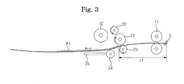
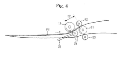
Figures 3 to 5 are views illustrating a printing medium discharging operation of the image forming apparatus ofFigure 1 ; and -
Figure 6 is a flowchart illustrating a method of successively transporting printing media in an image forming apparatus according to an exemplary embodiment of the present invention. - In the following description, it will be explained that the present invention is applied to a laser printer capable of color printing and duplex printing, however the present invention is not restricted thereto and can also be applied to other types of image forming apparatuses, e.g., an ink-jet printer, a multi-function printer, a copying machine, and the like, through adequate changes or modifications within the scope of the invention.
-
Figure 1 shows an image forming apparatus comprising a main body 1 which forms an exterior appearance, a printing medium feeding unit 2 which is mounted to a lower portion of the main body 1 and can be pulled to a front of the image forming apparatus to supply printing media such as paper to be printed, aprint unit 3 which is provided at an inner front portion of the main body 1 to print color images on the papers supplied from the printing medium feeding unit 2, and a printingmedium discharge unit 10 which discharges the printed papers outwardly to a front exterior of the main body 1. - The printing medium feeding unit 2 includes a
printing medium tray 2a on which the papers P are loaded, and aspring 2b to elastically support theprinting medium tray 2a. The papers P loaded on theprinting medium tray 2a are picked up by a pickup roller 2c sheet by sheet and are moved to theprint unit 3 through aregister roller 2d. A manual printingmedium feeding tray 2f is provided at the front portion of the main body 1, on which one or more sheets of paper can be swiftly loaded as needed. - The
print unit 3 includes exposure and developing devices 5 and 6 to form a color toner image (e.g., yellow, magenta, cyan and black) on aphotosensitive drum 4, a transfer device 7 to transfer the toner image formed on thephotosensitive drum 4 to the paper, and afixing device 8 to fix the toner image by applying heat pressure to the paper. Typically, the above devices 5 to 8 are unitarily provided, respectively, for convenient maintenance and repair. Especially, the exposure device 5 is disposed at the inner rear portion of the main body 1, and the developing device 6, the transfer device 7, and thefixing device 8 are disposed at an inner front portion of the main body 1. - The
print unit 3, the transfer device 7, thefixing device 8, and/or the return unit 9 may constitute an image forming unit to form an image on a printing medium and to feed the printing medium toward thedischarge unit 10. The printingmedium discharge unit 10 feeds the printed paper, which has passed through thefixing device 8, to adischarge tray 1a which is provided at an upper front portion of the main body 1. The printingmedium discharge unit 10 includes a plurality ofdischarge rollers - Referring to
Figure 2 , the printingmedium discharge unit 10 includes afirst discharge roller 11 which is provided adjacent to thefixing device 8 to discharge the printed paper, areverse roller 12 to reverse a moving direction of the paper fed from thefirst discharge roller 11, and asecond discharge roller 13 to discharge the paper fed from thereverse roller 12 outside. Thefirst discharge roller 11 and thesecond discharge roller 13 respectively include a pair of unit rollers. - In order to discharge the printed paper to the front of the main body 1, the
reverse roller 12 is provided at the inner rear portion of the main body 1, and thefirst discharge roller 11 and thesecond discharge roller 13 are provided at the inner front portion of the main body 1. Thesecond discharge roller 13 is disposed above thefirst discharge roller 11. In other words, the moving direction of the printed paper from thefirst discharge roller 11 to thereverse roller 12 is opposite to the moving direction of the printed paper from thereverse roller 12 to thesecond discharge roller 13. - Also, an intermediate
discharge roller unit 20 is provided between thefirst discharge roller 11 and thereverse roller 12. The intermediatedischarge roller unit 20 includes amain roller 21 to generate a driving force, asub discharge roller 22 and asub supply roller 23 which are in contact with themain roller 21 to be rotated by the driving force of themain roller 21. The positions of thesub discharge roller 22 and thesub supply roller 23 are determined according to the moving direction of the printed paper fed from thefirst discharge roller 11 to thesecond discharge roller 13 via thereverse roller 12. Accordingly, thesub discharge roller 22 and thesub supply roller 23 are disposed such that the moving direction of the printed paper passing between themain roller 21 and thesub supply roller 23 is opposite to the moving direction of the printed paper passing between themain roller 21 and thesub discharge roller 22. The intermediatedischarge roller unit 20 is located adjacent to thereverse roller 12, the detailed description of which will be made later. - Further, a
swing roller 24 is provided adjacent to thereverse roller 12. Theswing roller 24 functions to guide the paper fed from thefirst discharge roller 11 to thesecond discharge roller 13 when thereverse roller 12 rotates in the reverse direction. Theswing roller 24 is connected to alever 25 which is pivotably provided, so that theswing roller 24 swings by thelever 25 and selectively comes into contact with thereverse roller 12. - Meanwhile, as illustrated in
Figure 1 , the image forming apparatus may further include a return unit 9 to perform duplex printing in the main body 1. Before the printing medium which is printed on one surface is completely discharged from the printingmedium discharge unit 10, the return unit 9 feeds the paper to a paper return path, which is separately provided in the main body, when thereverse roller 12 rotates in the reverse direction, so that the paper passes again through theprint unit 3 via the paper return path and is printed on the other surface. The return unit 9 includes a plurality ofduplex rollers - Hereinafter, the operation of the image forming apparatus according to the present invention structured as above will be described with reference to
Figures 3 to 5 . A sensor S is provided between the fixing device 8 (Figure 2 ) of theprint unit 3 and thefirst discharge roller 11 to sense the rear end of the paper. If the sensor S senses a rear end of the paper, thereverse roller 12 rotates in the reverse direction when a predetermined time t1 elapses. - Referring to
Figures 1 and2 , if an image signal is input to the image forming apparatus to perform the print operation, the paper P1 loaded on theprinting medium tray 2a is picked up by the pickup roller 2c, and the toner image is formed on the paper P1 while the paper P1 passes through theprint unit 3. While the paper passes through the fixingdevice 8, the toner image is fixed to the paper. - Referring to
Figures 2-5 , after passing through the fixingdevice 8, the printed paper passes through thefirst discharge roller 11. At this time, the sensor S senses the rear end of the printed paper P1. The timing of rotating thereverse roller 12 in the reverse direction is determined according to a printing mode selected such as single-sided printing or duplex printing. For example, in the single-sided printing mode, thereverse roller 12 rotates in the reverse direction after the paper passes through thefirst discharge roller 11. Alternatively, in the duplex printing mode, thereverse roller 12 rotates in the reverse direction before the paper passes completely through thefirst discharge roller 11. In the following description, only the single-sided printing will be described. - Referring to
Figure 3 , after the sensor S senses the rear end of the printed paper P1 having passed through thefirst discharge roller 11, the printed paper P1 moves for the predetermined time t1. For the predetermined time t1, the printed paper P1 passes between themain roller 21 and thesub supply roller 23 of the intermediatedischarge roller unit 20. The time t1 is stored in the image forming apparatus in advance, which is calculated from the moving speed and the moving distance of the printed paper. - Referring to
Figures 2 and4 , thereverse roller 12 operates in advance to prepare to reverse the moving direction of the printed paper P1. That is, when the time t1 elapses, theswing roller 24 comes into contact with thereverse roller 12 to reverse the moving direction of the printed paper P1, and accordingly the rear end of the printed paper P1 advances between themain roller 21 and thesub discharge roller 22 of the intermediatedischarge roller unit 20. A time t2 required for the printed paper P1 to arrive at the intermediatedischarge roller unit 20 from thereverse roller 12 is stored in the image forming apparatus in advance, which is calculated from the moving speed of the printed paper and the distance between thereverse roller 12 and the intermediatedischarge roller unit 20. - Referring to
Figure 5 , when the printed paper P1 advances between themain roller 21 and thesub discharge roller 22 after the predetermined time t2 elapses, theswing roller 24 moves away from thereverse roller 12 and returns to its original position. At this time, the front end of the following sheet of printed paper P2 advances between themain roller 21 and thesub supply roller 23 of the intermediatedischarge roller unit 20. - The advance of the following sheet of printed paper P2 into the intermediate
discharge roller unit 20 is determined from the predetermined interval between the preceding sheet of printed paper and the following sheet of printed paper. For instance, the interval between the preceding sheet of printed paper P1 and the following sheet of printed paper P2 may be calculated from the total time T which sums up the above described time t1 and t2 and the time required for theswing roller 24 to contact and move away from thereverse roller 12 and the moving speed of the printed paper. - That is, by regulating the above described time T required to move the preceding sheet of printed paper P1 and the time required for the following sheet of printed paper P2 to arrive the intermediate
discharge roller unit 20, the discharge of the preceding sheet of printed paper P1 from the intermediatedischarge roller unit 20 and the advance of the following sheet of printed paper P2 into the intermediatedischarge roller unit 20 can be performed at the same time. Because the interval between the preceding sheet of printed paper P1 and the following sheet of printed paper P2 becomes shorter than that of the conventional image forming apparatus, the overall speed of successively discharging the printed papers increases. - The operation of the image forming apparatus will be further described based on the experimental results. The experiment was made under the conditions that the process speed is 150 mm/sec and the interval between the papers is 75 mm (500 ms).
- After the sensor S senses the rear end of the preceding sheet of printed paper P1, the time required for the rear end of the preceding sheet of printed paper P1 to pass between the
main roller 21 and thesub supply roller 23 of the intermediatedischarge roller unit 20 is 50 ms. At this time, thereverse roller 12 operates in advance to prepare to reverse the moving direction of the printed paper P1. - After the lapse of 50 ms, the
swing roller 24 swings upward for 100 ms and comes into contact with thereverse roller 12 to reverse the moving direction of the preceding sheet of printed paper P1. Then, the rear end of the preceding sheet of printed paper P1 advances between themain roller 21 and thesub discharge roller 22 of the intermediatedischarge roller unit 20. - After the lapse of 200 ms, the
swing roller 24 swings downward for 100 ms to move away from thereverse roller 12 and returns to its original position. - Accordingly, the total time required for the rear end of the preceding sheet of printed paper P1 to advance between the
main roller 21 and thesub discharge roller 22 of the intermediatedischarge roller unit 20 is 450 ms (50 + 100 + 200 + 100 = 450). Because the interval between the preceding sheet of printed paper P1 and the following sheet of printed paper P2 is 500 ms, the front end of the following sheet of printed paper P2 advances between themain roller 21 and thesub supply roller 23 while the preceding sheet of printed paper P1 arrives between themain roller 21 and thesub discharge roller 22. The front end of the preceding sheet of printed paper P1 passes through thereverse roller 21 before the rear end of the following sheet of printed paper P2 passes through the intermediatedischarge roller unit 20. - Referring to
Figure 6 , inoperation 610, a determination is made as to whether a rear end of a printing medium is detected. If so, inoperation 620, a swing roller moves to interact with a reverse roller after a predetermined time period to reverse a moving direction of the printing medium. Inoperation 630, a determination is made as to whether the redirected printing medium advances to an intermediate discharge roller unit. If so, inoperation 640, the swing roller is moved away from the reverse roller. Inoperation 650, a following printing medium successively fed from a print unit is advanced to the intermediate discharge roller unit. - The present invention can also be embodied as computer-readable codes on a computer-readable medium. The computer-readable medium can include a computer-readable recording medium and a computer-readable transmission medium. The computer-readable recording medium is any data storage device that can store data that can be thereafter read by a computer system. Examples of the computer-readable recording medium include read-only memory (ROM), random-access memory (RAM), CD-ROMs, magnetic tapes, floppy disks, and optical data storage devices. The computer-readable recording medium can also be distributed over network coupled computer systems so that the computer-readable code is stored and executed in a distributed fashion. The computer-readable transmission medium can transmit carrier waves or signals (e.g., wired or wireless data transmission through the Internet). Also, functional programs, codes, and code segments to accomplish the present invention can be easily construed by programmers skilled in the art to which the present invention pertains.
- As apparent from various embodiments of the image forming apparatus according to the present invention is equipped with the intermediate discharge roller unit between the first discharge roller and the reverse roller so that the discharge of the preceding sheet of printed paper from the printing medium discharge unit and the supply of the following sheet of printed paper into the printing medium discharge unit can be performed at the same time. Accordingly, the interval between the preceding sheet of printed paper and the following sheet of printed paper decreases, and thus the overall print speed increases.
- Although various embodiments of the present invention have been illustrated and described, it would be appreciated by those skilled in the art that changes may be made within the scope of the invention, defined in the claims hereafter.
Claims (16)
- An image forming apparatus having an intermediate discharge unit to feed printed printing media, comprising a main roller and two secondary rollers in contact with the main roller, wherein the intermediate discharge unit is configured to feed one printed printing medium in a first direction between the main roller and one secondary roller, whilst simultaneously feeding another printed printing medium in a second direction between the main roller and the other secondary roller.
- The image forming apparatus according to claim 1 further comprising a print unit, a first discharge roller to feed a printed printing medium from the print unit, a reverse roller to reverse a feed direction of the printed printing medium fed from the first discharge roller and a second discharge roller to discharge the printed printing medium whose feed direction is reversed, wherein the intermediate discharge unit is provided between the first discharge roller and the reverse roller.
- The image forming apparatus according to claim 2, wherein one secondary roller comprises a sub-supply roller to feed the printed printing medium from the first discharge roller to the reverse roller, and the other secondary roller comprises a sub-discharge roller to feed the printed printing medium from the reverse roller to the second discharge roller.
- The image forming apparatus according to claim 3, further comprising a swing roller which is provided adjacent to the reverse roller to guide the printed printing medium fed from the first discharge roller to the second discharge roller.
- The image forming apparatus according to claim 4, wherein when a rear end of the printed printing medium passes between the main roller and the sub supply roller, the swing roller contacts the reverse roller to reverse the moving direction of the printed printing medium, and when the rear end of the printed printing medium whose moving direction is reversed advances between the main roller and the sub discharge roller, the swing roller moves away from the reverse roller.
- The image forming apparatus according to claim 5, wherein the swing roller moves away from the reverse roller before the following printed printing medium is fed to the main roller and the sub supply roller.
- The image forming apparatus according to claim 5, further comprising a sensor to sense a rear end of the printed printing medium, wherein a time required for the rear end of the preceding printed printing medium to advance between the main roller and the sub discharge roller of the intermediate discharge roller unit via the first discharge roller and the reverse roller after the rear end of the preceding printed printing medium is sensed by the sensor is shorter than a time required for the following printed printing medium to advance between the main roller and the sub supply roller of the intermediate discharge roller unit.
- The image forming apparatus according to claim 7, wherein if a time required for the rear end of the printed printing medium to pass between the main roller and the sub supply roller of the intermediate discharge roller unit after the rear end of the printed printing medium is sensed by the sensor is 50 ms, an ascending time of the swing roller is 100 ms, a descending time of the swing roller is 100 ms, a process speed is 150 mm/sec, and an interval between the printing media is 75 mm, a distance between the reverse roller and the intermediate discharge roller unit is 20 mm.
- A method to control an image forming apparatus having an intermediate discharge unit to feed printed printing media, comprising a main roller and two secondary rollers in contact with the main roller, wherein the intermediate discharge unit is configured to feed a one printed printing medium in a first direction between the main roller and one secondary roller, whilst simultaneously feeding another printed printing medium in a second direction between the main roller and the other secondary roller, a print unit, and a sensor to sense a rear end of the printed printing medium, the method comprising if the rear end of a preceding printed printing medium is sensed by the sensor, reversing the moving direction of the preceding printed printing medium after lapse of a predetermined time and if the preceding printed printing medium whose moving direction is reversed advances between the main roller and one secondary roller, advancing a following printed printing medium successively fed from the print unit between the main roller and the other secondary roller.
- The method according to claim 9, wherein the image forming apparatus further comprises a first discharge roller to feed a printed printing medium from the print unit, a reverse roller to reverse a feed direction of the printed printing medium fed from the first discharge roller and a second discharge roller to discharge the printed printing medium whose feed direction is reversed, wherein the intermediate discharge unit is provided between the first discharge roller and the reverse roller, the step of reversing the moving direction of the preceding printed printing medium is effected by the reverse roller.
- The method according to claim 10, wherein a swing roller is provided adjacent to the reverse roller to guide the printed printing medium fed from the first discharge roller to the second discharge roller, and one secondary roller comprises a sub-supply roller to feed the printed printing medium from the first discharge roller to the reverse roller, and the other secondary roller comprises a sub-discharge roller to feed the printed printing medium from the reverse roller to the second discharge roller, the method further comprises if the rear end of the printed printing medium passes between the main roller and the sub supply roller, contacting the swing roller to the reverse roller to reverse the moving direction of the printed printing medium, and if the rear end of the printed printing medium whose moving direction is reversed advances between the main roller and the sub discharge roller, making the swing roller move away from the reverse roller.
- The method according to claim 11, wherein the swing roller moves away from the reverse roller before the following printed printing medium is fed to the main roller and the sub supply roller.
- An image forming apparatus, comprising an intermediate discharge roller unit having a swing roller to move between a first position and a second position based on at least one or more predetermined time periods and a selected printing mode, and a reverse roller to interact with the swing roller in the second position to change a path of the printing medium.
- The apparatus of claim 13, further comprising a sensor to sense the printing medium, and the swing roller moves to the second position and interacts with the reverse roller based on a first predetermined time period after the sensor senses the printing medium.
- The apparatus of claim 14, further comprising an intermediate discharge roller unit disposed proximate to the reverse roller, and to discharge the printing medium, and the swing roller moves to the first position away from the reverse roller based on a second predetermined time period corresponding to an amount of time for the printing medium to arrive at the intermediate discharge roller unit from the reverse roller.
- The apparatus of claim 15, wherein a front end of a preceding printing medium passes through the reverse roller before a rear end of a following printing medium passes through the intermediate discharge roller unit.
Applications Claiming Priority (1)
| Application Number | Priority Date | Filing Date | Title |
|---|---|---|---|
| KR1020070010657A KR101460537B1 (en) | 2007-02-01 | 2007-02-01 | Image forming apparatus and control method therefor |
Publications (1)
| Publication Number | Publication Date |
|---|---|
| EP1954021A1 true EP1954021A1 (en) | 2008-08-06 |
Family
ID=39365841
Family Applications (1)
| Application Number | Title | Priority Date | Filing Date |
|---|---|---|---|
| EP07124135A Ceased EP1954021A1 (en) | 2007-02-01 | 2007-12-28 | Image forming apparatus and control method thereof |
Country Status (4)
| Country | Link |
|---|---|
| US (2) | US8750779B2 (en) |
| EP (1) | EP1954021A1 (en) |
| KR (1) | KR101460537B1 (en) |
| CN (2) | CN101236370B (en) |
Families Citing this family (8)
| Publication number | Priority date | Publication date | Assignee | Title |
|---|---|---|---|---|
| KR101460537B1 (en) * | 2007-02-01 | 2014-11-12 | 삼성전자 주식회사 | Image forming apparatus and control method therefor |
| KR101674563B1 (en) * | 2009-01-12 | 2016-11-22 | 삼성전자주식회사 | Reversely transferring unit of a printing medium and image forming apparatus including the same |
| JP5488790B2 (en) * | 2009-05-20 | 2014-05-14 | セイコーエプソン株式会社 | Recording device |
| JP5970895B2 (en) | 2012-03-22 | 2016-08-17 | 富士ゼロックス株式会社 | Sheet conveying apparatus, image reading apparatus, and image forming apparatus |
| JP6171521B2 (en) * | 2013-04-16 | 2017-08-02 | カシオ電子工業株式会社 | Transport direction switching device, transport direction switching method, and image forming apparatus |
| KR101532205B1 (en) * | 2014-07-23 | 2015-07-01 | 삼성전자주식회사 | Image Forming Apparatus and Control Method Thereof |
| JP6397268B2 (en) * | 2014-08-25 | 2018-09-26 | キヤノン株式会社 | Recording apparatus, control method therefor, program, and storage medium |
| KR101953783B1 (en) * | 2016-05-24 | 2019-03-11 | 심상영 | Duplex printing method using the seat printer which was available for a duplex printing |
Citations (9)
| Publication number | Priority date | Publication date | Assignee | Title |
|---|---|---|---|---|
| US5689792A (en) * | 1995-12-01 | 1997-11-18 | Xerox Corporation | Simplified and higher productivity duplex document scanning systems |
| EP0851310A2 (en) * | 1996-12-24 | 1998-07-01 | Canon Kabushiki Kaisha | Sheet conveying apparatus |
| US6145834A (en) | 1997-06-12 | 2000-11-14 | Konica Corporation | Automatic document feeder having a document shunting path |
| JP2001159835A (en) * | 1999-12-02 | 2001-06-12 | Matsushita Electric Ind Co Ltd | Automatic double-sided printing device for electrophotographic equipment |
| US6304743B1 (en) * | 1998-12-15 | 2001-10-16 | Canon Kabushiki Kaisha | Image formation method and apparatus for double-faced originals with different orders of image reading and image forming |
| US20020054382A1 (en) * | 2000-08-25 | 2002-05-09 | Murata Kikai Kabushiki Kaisha | Duplex automatic document feeder |
| US6574011B1 (en) * | 1997-10-27 | 2003-06-03 | Canon Kabushiki Kaisha | Image formation apparatus |
| US20060220309A1 (en) * | 2005-03-17 | 2006-10-05 | Brother Kogyo Kabushiki Kaisha | Image-forming device |
| US20060291898A1 (en) * | 2005-06-24 | 2006-12-28 | Fuji Xerox Co., Ltd. | Image forming device and process cartridge |
Family Cites Families (29)
| Publication number | Priority date | Publication date | Assignee | Title |
|---|---|---|---|---|
| US3942785A (en) * | 1974-11-25 | 1976-03-09 | Xerox Corporation | Self-actuating sheet inverter reverser |
| JPS6012557A (en) | 1983-07-04 | 1985-01-22 | Ricoh Co Ltd | Carrier for electrostatic latent image developer |
| JPS60216346A (en) * | 1984-04-11 | 1985-10-29 | Sharp Corp | Automatic original feeding device of copying machine |
| JPS6188956U (en) * | 1984-11-17 | 1986-06-10 | ||
| JPS62140969A (en) * | 1985-12-17 | 1987-06-24 | Ricoh Co Ltd | Paper reversal conveyance device |
| JPH0825695B2 (en) * | 1986-05-30 | 1996-03-13 | 日立工機株式会社 | Duplex printing device |
| JP2763359B2 (en) * | 1989-12-28 | 1998-06-11 | 三田工業株式会社 | Sheet reversing device |
| JP3099871B2 (en) * | 1996-07-31 | 2000-10-16 | キヤノン株式会社 | Image forming device |
| US6239864B1 (en) * | 1998-04-30 | 2001-05-29 | Ricoh Co., Ltd. | Image forming apparatus with a paper positioning device |
| JP2000321953A (en) * | 1999-05-10 | 2000-11-24 | Minolta Co Ltd | Image forming device |
| US6446958B1 (en) * | 1999-11-18 | 2002-09-10 | Pitney Bowes Inc. | Method and system for directing an item through the feed path of a folding apparatus |
| US6798430B2 (en) * | 2000-06-14 | 2004-09-28 | Brother Kogyo Kabushiki Kaisha | Tandem type color image forming device having a plurality of process cartridges arrayed in running direction of intermediate image transfer member |
| US6567643B2 (en) * | 2000-09-27 | 2003-05-20 | Ricoh Company, Ltd. | Apparatuses for color image formation, tandem color image formation and image formation |
| JP3754899B2 (en) * | 2001-03-09 | 2006-03-15 | キヤノン株式会社 | Sheet guide means and image forming apparatus provided with the same |
| JP2003300642A (en) * | 2002-04-09 | 2003-10-21 | Canon Inc | Image forming device |
| JP2003323100A (en) * | 2002-05-02 | 2003-11-14 | Canon Inc | Image forming device |
| JP2004037685A (en) * | 2002-07-02 | 2004-02-05 | Canon Inc | Image forming device |
| JP2004292150A (en) * | 2003-03-28 | 2004-10-21 | Canon Inc | Image forming device |
| JP4455160B2 (en) * | 2003-06-16 | 2010-04-21 | キヤノン株式会社 | Image forming apparatus |
| JP4482297B2 (en) * | 2003-07-31 | 2010-06-16 | 株式会社リコー | Electrophotographic equipment |
| JP2005219273A (en) * | 2004-02-04 | 2005-08-18 | Ricoh Co Ltd | Power storage device, fixing device, and image forming apparatus |
| KR100622401B1 (en) * | 2004-05-17 | 2006-09-19 | 삼성전자주식회사 | Paper reversing device of image forming apparatus |
| JP2006058459A (en) * | 2004-08-18 | 2006-03-02 | Canon Inc | Spacing member, process cartridge, and electrophotographic image forming apparatus |
| JP4417281B2 (en) * | 2005-03-18 | 2010-02-17 | ブラザー工業株式会社 | Image forming apparatus |
| JP4232106B2 (en) * | 2005-04-22 | 2009-03-04 | 村田機械株式会社 | Image forming apparatus |
| JP4561515B2 (en) * | 2005-07-25 | 2010-10-13 | 富士ゼロックス株式会社 | Image forming apparatus |
| JP4176100B2 (en) * | 2005-10-06 | 2008-11-05 | シャープ株式会社 | Image forming apparatus |
| KR101460537B1 (en) * | 2007-02-01 | 2014-11-12 | 삼성전자 주식회사 | Image forming apparatus and control method therefor |
| JP4950014B2 (en) * | 2007-12-09 | 2012-06-13 | 株式会社リコー | Sheet conveying apparatus, image forming apparatus equipped with the same, electrophotographic copying machine, printer, facsimile, digital multifunction machine |
-
2007
- 2007-02-01 KR KR1020070010657A patent/KR101460537B1/en not_active Expired - Fee Related
- 2007-12-10 US US11/953,236 patent/US8750779B2/en active Active
- 2007-12-28 CN CN2007103058733A patent/CN101236370B/en not_active Expired - Fee Related
- 2007-12-28 EP EP07124135A patent/EP1954021A1/en not_active Ceased
- 2007-12-28 CN CN200910205042A patent/CN101676813A/en active Pending
-
2014
- 2014-05-01 US US14/267,269 patent/US9213285B2/en not_active Expired - Fee Related
Patent Citations (9)
| Publication number | Priority date | Publication date | Assignee | Title |
|---|---|---|---|---|
| US5689792A (en) * | 1995-12-01 | 1997-11-18 | Xerox Corporation | Simplified and higher productivity duplex document scanning systems |
| EP0851310A2 (en) * | 1996-12-24 | 1998-07-01 | Canon Kabushiki Kaisha | Sheet conveying apparatus |
| US6145834A (en) | 1997-06-12 | 2000-11-14 | Konica Corporation | Automatic document feeder having a document shunting path |
| US6574011B1 (en) * | 1997-10-27 | 2003-06-03 | Canon Kabushiki Kaisha | Image formation apparatus |
| US6304743B1 (en) * | 1998-12-15 | 2001-10-16 | Canon Kabushiki Kaisha | Image formation method and apparatus for double-faced originals with different orders of image reading and image forming |
| JP2001159835A (en) * | 1999-12-02 | 2001-06-12 | Matsushita Electric Ind Co Ltd | Automatic double-sided printing device for electrophotographic equipment |
| US20020054382A1 (en) * | 2000-08-25 | 2002-05-09 | Murata Kikai Kabushiki Kaisha | Duplex automatic document feeder |
| US20060220309A1 (en) * | 2005-03-17 | 2006-10-05 | Brother Kogyo Kabushiki Kaisha | Image-forming device |
| US20060291898A1 (en) * | 2005-06-24 | 2006-12-28 | Fuji Xerox Co., Ltd. | Image forming device and process cartridge |
Also Published As
| Publication number | Publication date |
|---|---|
| US20140241774A1 (en) | 2014-08-28 |
| US8750779B2 (en) | 2014-06-10 |
| KR101460537B1 (en) | 2014-11-12 |
| CN101236370B (en) | 2010-09-29 |
| US9213285B2 (en) | 2015-12-15 |
| CN101236370A (en) | 2008-08-06 |
| CN101676813A (en) | 2010-03-24 |
| US20080187381A1 (en) | 2008-08-07 |
| KR20080072215A (en) | 2008-08-06 |
Similar Documents
| Publication | Publication Date | Title |
|---|---|---|
| US9213285B2 (en) | Image forming apparatus and control method thereof | |
| US8833893B2 (en) | Method of printing and printing apparatus | |
| JP2005200133A (en) | Image forming apparatus | |
| US8428505B2 (en) | Image forming apparatus | |
| KR100655931B1 (en) | Recording medium conveying apparatus and recording medium conveying method | |
| US20070071461A1 (en) | Printing apparatus | |
| US10534301B2 (en) | Medium supply device and image forming apparatus | |
| JP4674473B2 (en) | Image forming apparatus and post-processing apparatus | |
| JP4360165B2 (en) | Printing apparatus and gap adjusting method | |
| JP5359428B2 (en) | Belt conveying device and belt conveying program | |
| US8768236B2 (en) | Duplex image forming apparatus | |
| JP4367303B2 (en) | Image recording device | |
| JP6403617B2 (en) | Image forming apparatus | |
| US7155153B2 (en) | Image transfer mechanism and image forming device using the mechanism | |
| JP4963632B2 (en) | Image forming apparatus | |
| JP6173096B2 (en) | Image forming apparatus | |
| JP3591976B2 (en) | Image forming device | |
| JP4995528B2 (en) | Image forming apparatus | |
| JP3896249B2 (en) | Paper feeding method in image forming apparatus | |
| JP7413838B2 (en) | Image forming device, paper feeding method for image forming device, paper feeding control program for image forming device | |
| JP2006030736A (en) | Color image forming apparatus | |
| JP4007259B2 (en) | Image forming apparatus | |
| JP2024147376A (en) | Image forming apparatus and image forming method | |
| JP2007193268A (en) | Image forming apparatus | |
| JP2011141463A (en) | Image forming apparatus and medium conveying method |
Legal Events
| Date | Code | Title | Description |
|---|---|---|---|
| PUAI | Public reference made under article 153(3) epc to a published international application that has entered the european phase |
Free format text: ORIGINAL CODE: 0009012 |
|
| AK | Designated contracting states |
Kind code of ref document: A1 Designated state(s): AT BE BG CH CY CZ DE DK EE ES FI FR GB GR HU IE IS IT LI LT LU LV MC MT NL PL PT RO SE SI SK TR |
|
| AX | Request for extension of the european patent |
Extension state: AL BA HR MK RS |
|
| 17P | Request for examination filed |
Effective date: 20080929 |
|
| 17Q | First examination report despatched |
Effective date: 20081030 |
|
| AKX | Designation fees paid |
Designated state(s): DE FR GB NL |
|
| RAP1 | Party data changed (applicant data changed or rights of an application transferred) |
Owner name: SAMSUNG ELECTRONICS CO., LTD. |
|
| RAP1 | Party data changed (applicant data changed or rights of an application transferred) |
Owner name: S-PRINTING SOLUTION CO., LTD. |
|
| RAP1 | Party data changed (applicant data changed or rights of an application transferred) |
Owner name: HP PRINTING KOREA CO., LTD. |
|
| APBK | Appeal reference recorded |
Free format text: ORIGINAL CODE: EPIDOSNREFNE |
|
| APBN | Date of receipt of notice of appeal recorded |
Free format text: ORIGINAL CODE: EPIDOSNNOA2E |
|
| APBR | Date of receipt of statement of grounds of appeal recorded |
Free format text: ORIGINAL CODE: EPIDOSNNOA3E |
|
| APAF | Appeal reference modified |
Free format text: ORIGINAL CODE: EPIDOSCREFNE |
|
| RAP1 | Party data changed (applicant data changed or rights of an application transferred) |
Owner name: HEWLETT-PACKARD DEVELOPMENT COMPANY, L.P. |
|
| APAF | Appeal reference modified |
Free format text: ORIGINAL CODE: EPIDOSCREFNE |
|
| APBX | Invitation to file observations in appeal sent |
Free format text: ORIGINAL CODE: EPIDOSNOBA2E |
|
| STAA | Information on the status of an ep patent application or granted ep patent |
Free format text: STATUS: EXAMINATION IS IN PROGRESS |
|
| APBT | Appeal procedure closed |
Free format text: ORIGINAL CODE: EPIDOSNNOA9E |
|
| STAA | Information on the status of an ep patent application or granted ep patent |
Free format text: STATUS: THE APPLICATION HAS BEEN REFUSED |
|
| 18R | Application refused |
Effective date: 20221217 |