EP1953911A2 - Control apparatus for automotive alternator and automotive power generation system - Google Patents
Control apparatus for automotive alternator and automotive power generation system Download PDFInfo
- Publication number
- EP1953911A2 EP1953911A2 EP08001429A EP08001429A EP1953911A2 EP 1953911 A2 EP1953911 A2 EP 1953911A2 EP 08001429 A EP08001429 A EP 08001429A EP 08001429 A EP08001429 A EP 08001429A EP 1953911 A2 EP1953911 A2 EP 1953911A2
- Authority
- EP
- European Patent Office
- Prior art keywords
- power generation
- control apparatus
- reset
- control circuit
- electric generator
- Prior art date
- Legal status (The legal status is an assumption and is not a legal conclusion. Google has not performed a legal analysis and makes no representation as to the accuracy of the status listed.)
- Granted
Links
- 238000010248 power generation Methods 0.000 title claims abstract description 123
- 230000001276 controlling effect Effects 0.000 claims description 17
- 230000004044 response Effects 0.000 claims description 14
- 230000001105 regulatory effect Effects 0.000 claims description 5
- 238000000034 method Methods 0.000 description 23
- 230000008569 process Effects 0.000 description 23
- 238000004891 communication Methods 0.000 description 19
- 230000005540 biological transmission Effects 0.000 description 11
- 238000010586 diagram Methods 0.000 description 4
- 230000008859 change Effects 0.000 description 3
- 239000000446 fuel Substances 0.000 description 3
- 230000006641 stabilisation Effects 0.000 description 2
- 238000011105 stabilization Methods 0.000 description 2
- 230000001939 inductive effect Effects 0.000 description 1
- 238000002347 injection Methods 0.000 description 1
- 239000007924 injection Substances 0.000 description 1
- 230000007257 malfunction Effects 0.000 description 1
- 239000000203 mixture Substances 0.000 description 1
- 238000012986 modification Methods 0.000 description 1
- 230000004048 modification Effects 0.000 description 1
Images




Classifications
-
- H—ELECTRICITY
- H02—GENERATION; CONVERSION OR DISTRIBUTION OF ELECTRIC POWER
- H02P—CONTROL OR REGULATION OF ELECTRIC MOTORS, ELECTRIC GENERATORS OR DYNAMO-ELECTRIC CONVERTERS; CONTROLLING TRANSFORMERS, REACTORS OR CHOKE COILS
- H02P9/00—Arrangements for controlling electric generators for the purpose of obtaining a desired output
- H02P9/14—Arrangements for controlling electric generators for the purpose of obtaining a desired output by variation of field
- H02P9/26—Arrangements for controlling electric generators for the purpose of obtaining a desired output by variation of field using discharge tubes or semiconductor devices
- H02P9/30—Arrangements for controlling electric generators for the purpose of obtaining a desired output by variation of field using discharge tubes or semiconductor devices using semiconductor devices
Definitions
- the present invention relates generally to control apparatus for electric generators and electric power generation systems.
- the invention relates to a control apparatus for an automotive alternator, which can reliably inform a reset thereof to an engine control unit (ECU), and an automotive power generation system that includes such a control apparatus.
- ECU engine control unit
- a conventional power generation system for a motor vehicle such as the one disclosed in U.S. Patent No. 5767636 , includes an automotive alternator, a voltage regulator for regulating the output voltage of the alternator, and an ECU that communicates with the voltage regulator for controlling power generation of the alternator. More specifically, the ECU sends to the voltage regulator a command signal that represents command values for power generation control parameters; the voltage regulator regulates the output voltage of the alternator according to the command signal. With such a configuration, it is possible to suitably control the power generation of the alternator according to the operating condition of the engine.
- the alternator is generally installed in an engine compartment and supplies electric power to both a battery and electric loads via a charge line.
- the alternator also supplies power to the voltage regulator which is generally built in the alternator.
- the voltage regulator may be falsely reset due to various noises imposed on the power lines of the power generation system.
- ignition noises may be imposed in the case of the engine being a gasoline engine; power noises may be imposed when the alternator drives an inductive load, such as a motor; great voltage ripples may be imposed when the power generation system operates without the battery.
- the present invention has been made in view of the above-mentioned problems.
- a control apparatus which controls power generation of an electric generator and communicates with an external control apparatus.
- the control apparatus includes: a control circuit that controls the power generation of the electric generator according to a command signal transmitted from the external control apparatus; means for reseting the control circuit; and means for informing the external control apparatus of a power generation condition of the electric generator by transmitting a condition signal, the condition signal indicating both the power generation condition of the electric generator and information on whether a reset of the control circuit is made by the reseting means.
- the control apparatus can reliably inform the external control apparatus of the reset of the control circuit.
- the informing means transmits the condition signal in a cycle of less than a half of a time consonant of field current supplied to the electric generator.
- the informing means sets a reset flag to a first value, cyclically transmits for a predetermined time period the condition signal which represents the first value of the reset flag, and then sets the reset flag to a second value, the first value of the reset flag indicating that a reset of the control circuit is made, the second value of the reset flag indicating that no reset of the control circuit is made, the predetermined time period being longer than at least twice the cycle in which the condition signal is transmitted.
- the external control apparatus can detect the occurrence rate of reset for the control circuit. Consequently, on the basis of the occurrence rate of reset, the external control apparatus can detect the fault conditions and optimally determine the command signal.
- the command signal may represent command values for power generation control parameters
- the condition signal may represent actual values of the power generation control parameters.
- the power generation control parameters may include an output voltage of the electric generator, field current supplied to the electric generator, and a duty of a power transistor for controlling the field current.
- the electric generator may be an automotive alternator; the control apparatus may be a voltage regulator for regulating an output voltage of the automotive alternator; the external control apparatus may be an engine control unit.
- an electric power generation system which includes an electric generator, and first and second control apparatus that communicate with each other to control power generation of the electric generator.
- the first control apparatus includes: a control circuit that controls the power generation of the electric generator according to a command signal transmitted from the second control apparatus; means for reseting the control circuit; and means for informing the second control apparatus of a power generation condition of the electric generator by transmitting a condition signal, the condition signal indicating both the power generation condition of the electric generator and information on whether a reset of the control circuit is made by the reseting means.
- the second control apparatus determines whether a reset of the control circuit of the first control apparatus is made on the basis of the condition signal transmitted from the first control apparatus.
- the first control apparatus can reliably inform the second control apparatus of the reset of the control circuit.
- the second control circuit when it is determined that a reset of the control circuit of the first control apparatus is made, transmits the command signal to the first control circuit.
- the informing means of the first control apparatus sets a reset flag to a first value, transmits to the second control apparatus the condition signal which represents the first value of the reset flag, and then sets the reset flag to a second value upon safe receipt of the command signal which is transmitted by the second control apparatus in response to the condition signal, the first value of the reset flag indicating that a reset of the control circuit is made, the second value of the reset flag indicating that no reset of the control circuit is made.
- the first control apparatus can be prevented from further informing the second control apparatus of the reset of the control circuit after the safe receipt of the command signal.
- the command signal may represent command values for power generation control parameters
- the condition signal may represent actual values of the power generation control parameters.
- the power generation control parameters may include an output voltage of the electric generator, field current supplied to the electric generator, and a duty of a power transistor for controlling the field current.
- the electric power generation system may be for use in a motor vehicle with the electric generator being an automotive alternator, the first control apparatus being a voltage regulator for regulating an output voltage of the automotive alternator, and the second control apparatus being an engine control unit for controlling an engine of the vehicle.
- FIGS. 1 - 7 One preferred embodiment of the present invention will be described hereinafter with reference to FIGS. 1 - 7 .
- FIG. 1 shows the overall configuration of an automotive power generation system S1 according to the present embodiment.
- the power generation system S1 includes an Engine Control Unit (ECU) 1, an engine 2, an automotive alternator (abbreviated to ALT in FIG.1 ) 3, a voltage regulator 4, a battery (abbreviated to BATT in FIG.1 ) 5, a motor 6, and electric loads 7.
- ECU Engine Control Unit
- ALT automotive alternator
- BATT battery
- the ECU 1 controls the output of the engine 2 on the basis of sensing signals output from various sensors for sensing the running condition of a vehicle driven by the engine 2.
- the ECU 1 also functions as an external control apparatus to the alternator 3.
- the alternator 3 is driven by the engine 2 via a belt 23.
- the electric power generated by the alternator 3 is used to charge the battery 5 and power the motor 6 and electric loads 7. More specifically, an output terminal of the alternator 3 is electrically connected to a positive terminal of the battery 5 via a charge line 43; both the motor 6 and electric loads 7 are connected to the charge line 43 via respective switches.
- the engine 2 includes a plurality of ignition devices 2A, each of which is powered by the battery 5 to ignite the air/fuel mixture in a corresponding a cylinder of the engine 2.
- the voltage regulator 4 which is built in the alternator 3 in the present embodiment, regulates the output voltage of alternator 3 by controlling field current supply to the alternator 3.
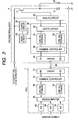
- FIG. 2 shows the detailed configuration of the ECU 1 and voltage regulator 4.
- the voltage regulator 4 includes a power transistor 11, a free-wheeling diode 12, an analog circuit 20, a power generation control circuit (abbreviated to P.G.C.C. in FIG. 2 ) 30, a driver 40, a power circuit 50, and a reset circuit 52.
- P.G.C.C. power generation control circuit
- the power transistor 11 is connected in series with a field coil 3A of the alternator 3, so that the field coil 3A can be supplied with field current when the power transistor 11 is turned on. More specifically, the power transistor 11 has its drain connected to the output terminal of the alternator 3 and its source connected to the field coil 3A.
- the free-wheeling diode 12 is connected in parallel with the field coil 3A, so that the electric energy stored in the field coil 3A can be removed from the field coil 3A when the power transistor 11 is turned off. More specifically, the free-wheeling diode 12 has its cathode connected to the source of the power transistor 11 and its anode grounded.
- the analog circuit 20 has both a function of detecting the power generating condition of the alternator 3 and a function of driving the power transistor 11 by sending a drive signal to the gate of the power transistor 11.
- the power generating condition of the alternator 3 is represented by actual values of power generation control parameters, such as the output voltage of the alternator 3, the field current supplied to the field coil 3A, and the duty of the power transistor 11.
- the analog circuit 20 includes a driver for driving the power transistor 11, an analog control circuit for controlling the driver, and detecting circuits for respectively detecting the output voltage of the alternator 3, the field current supplied to the field coil 3A, and the duty of the power transistor 11.
- the analog control circuit is controlled by the power generation control circuit 30.
- the power generation control circuit 30 has both a function of controlling the power generation of the alternator 3 according to a command signal sent from the ECU 1 and a function of sending to the ECU 1 a condition signal that indicates the power generating condition of the alternator 3.
- the command signal represents command values for the power generation control parameters
- the condition signal represents the actual values of the power generation control parameters detected by the analog circuit 20.
- the power generation control circuit 30 includes a digital circuit 32, a condition signal storage 34 in which the condition signal (i.e., the actual values of the power generation control parameters) is stored, a communication controller 36, and a command signal storage 38 in which the command signal (i.e., the command values for the power generation control parameters) is stored.
- the digital circuit 32 generates the condition signal on the basis of the actual values of the power generation control parameters detected by the analog circuit 20. The generated condition signal is then stored in the condition signal storage 34.
- the digital circuit 32 also has a power generation control function which is to be described in detail later.
- FIG. 3 shows a digital format of the condition signal that is transmitted from the voltage regulator 4 to the ECU 1 via a serial communication according to the LIN protocol.
- the condition signal includes, after the sync field and transmission ID field, a voltage response field, a field current response field, a duty response field, a diagnostic information field, and a check data field.
- the transmission ID field contains an identifier which is assigned according to a transmission request from the ECU 1 and has a value set according to the transmission request.
- the voltage response field contains response data representing the actual value of the output voltage of the alternator 3 which is detected by the analog circuit 20.
- the field current response field contains response data representing the actual value of the field current supplied to the field coil 3A which is detected by the analog circuit 20.
- the duty response field contains response data representing the actual value of the duty of the power transistor 11 which is detected by the analog circuit 20.
- the diagnostic information field contains response data of predetermined bits representing diagnostic information.
- the head bit of the diagnostic information field is used for a reset flag which is described in detail later.
- the check data field contains data for check, such as parity and CRC data.
- the communication controller 36 of the power generation control circuit 30 has a function of modulating the condition signal stored in the condition signal storage 34 into the digital format shown in FIG. 3 .
- the driver 40 functions both as a transmitter to transmit the modulated condition signal to the ECU 1 via a communication line 80 and as a receiver to receive a modulated command signal from the ECU 1 via the communication line 80.
- the above-described communication controller 36 also has a function of demodulating the modulated command signal received by the driver 40.
- the command signal demodulated by the communication controller 36 is then stored in the command signal storage 38.
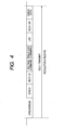
- FIG. 4 shows a digital format of the command signal that is transmitted from the ECU 1 to the voltage regulator 4 via the serial communication according to the LIN protocol.
- the command signal includes, after the sync filed and reception ID field, a voltage command field, a field current command field, an LRC field, a vehicle information field, and a check data field.
- the voltage command field contains command data representing the target value of the output voltage of the alternator 3.
- the field current command field contains command data representing limit values of the field current supplied to the field coil 3A.
- the LRC field contains command data representing limit values of changes in the field current supplied to the field coil 3A and in the duty of the power transistor 11 when the total load of the alternator 3 (i.e., the motor 6 plus the electric loads 7) changes rapidly.
- the digital circuit 32 controls, via the analog circuit 20, the power generation of the alternator 3 according to the command signal stored in the command signal storage 38.
- the digital circuit 32 controls the analog circuit 20 to drive the power transistor 11 so as to bring the actual value of the output voltage detected by the analog circuit 20 into agreement with the target value of the output voltage indicated by the command signal.
- the digital circuit 32 controls the analog circuit 20 to drive the power transistor 11 so as to limit the actual value of the field current detected by the analog circuit 20 within the limit values of the field current indicated by the command signal.
- the digital circuit 32 controls the analog circuit 20 to drive the power transistor 11 so as to limit the changes in the actual values of the field current and duty of the power transistor 11 detected by the analog circuit 20 within the respective limit values of those changes indicated by the command signal.
- the power circuit 50 serves to supply electric power to each component of the voltage regulator 4.
- the reset circuit 52 resets the power generation control circuit 30 at predetermined timings.
- the reset operation of the reset circuit 52 is generally made when the voltage regulator 4 is activated.
- the reset operation also may be falsely made when great ignition noises are induced in sync with the ignition timings of the ignition devices 2A and transmitted to the voltage regulator 4 via the output terminal of the alternator 3.
- the reset circuit 52 sends a reset signal to the power generation control circuit 30.
- the power generation control circuit 30 is reset, so that the command signal (i.e., the command values) stored in the command signal storage 38 is initialized.
- the digital circuit 32 sets to "1" the value of the reset flag which is the head bit of the condition signal stored in the condition signal storage 34.
- the ECU 1 includes, as shown in FIG. 2 , a microcomputer 60, A/D converters 62, 64, and 66, a command signal storage 70 in which the command signal (i.e., the command values for the power generation control parameters) is stored, a communication controller 72, a driver 74, and a condition signal storage 76 in which the condition signal (i.e., the actual values of the power generation control parameters) is stored.
- the microcomputer 60 adjusts, for example, the fuel injection quantities of the engine 2 and the ignition timings of the ignition devices 2A on the basis of the sensing signals input via the A/D converters 62, 64, and 66, thereby controlling the engine 2.
- the sensing signals are output from various sensors, such as a vehicle speed sensor, a throttle sensor, and an 02 sensor. Further, the microcomputer 60 generates the command signal according to the operating condition of the engine 2. The generated command single is then stored in the command signal storage 70.
- the communication controller 72 has a function of modulating the command signal stored in the command signal storage 70 into the digital format shown in FIG. 4 .
- the driver 74 functions both as a transmitter to transit the modulated command signal to the voltage regulator 4 via the communication line 80 and as a receiver to receive the modulated condition signal from the voltage regulator 4 via the communication line 80.
- the above-described communication controller 72 also has a function of demodulating the modulated condition signal received by the driver 74.
- the condition signal demodulated by the communication controller 72 is then stored in the condition single storage 76 and further used by the microcomputer 60 to control the engine 2.
- the reset circuit 52 makes up means for resetting the power generation control circuit 30; the digital circuit 32, condition signal storage 34, communication controller 36, and driver 40 together make up means for informing the ECU 1 of a reset of the power generation control circuit.
- FIG. 5 shows a process of the ECU 1 for controlling the power generation of the alternator 3 in cooperation with the voltage regulator 4.
- the ECU 1 receives the condition signal transmitted by the voltage regulator 4.
- the ECU 1 determines whether or not the reset flag is included in the condition signal.
- step 101 determines a failure in resetting the power generation control circuit 30 of the voltage regulator 4 and performs necessary processes.
- the determination at step 101 will produce a "NO" answer.
- the ECU 1 determines that a reset of the power generation control circuit 30 of the voltage regulator 4 has failed and takes necessary steps.
- step 101 determines whether the command values for the power generation control parameters. If the determination at step 101 produces a "YES" answer, then the process goes on to step 103, at which the ECU 1 transmits to the voltage regulator 4 the command signal that indicates the command values for the power generation control parameters.
- the ECU 1 receives again the condition signal (more precisely, the next condition signal).
- the ECU 1 determines whether or not the value of the reset flag in the condition signal received at step S104 is equal to "1".
- step 105 determines whether the determination at step 105 produces a "NO" answer. If the determination at step 105 produces a "NO" answer, then the process proceeds to step 106, at which the ECU 1 performs its normal control on the power generation of the alternator 3. Thereafter, the process returns to step 104 to repeat the subsequent steps.
- the ECU 1 determines that no reset of the power generation control circuit 30 of the voltage regulator 4 has been made in the present cycle, and thus does not send to the voltage regulator 4 the command values for the power generation control parameters.
- step 105 determines whether the ECU 1 transmits the command signal to the voltage regulator 4.
- step 107 the ECU 1 transmits the command signal to the voltage regulator 4. Then, the process returns to step 104 to repeat the subsequent steps.
- the ECU 1 determines that a reset of the power generation control circuit 30 of the voltage regulator 4 has been made in the present cycle, and thus sends to the voltage regulator 4 the command values for the power generation control parameters by transmitting the command signal.
- FIG. 6 shows a process of the voltage regulator 4 for controlling the power generation of the alternator 3 in cooperation with the ECU 1.
- the voltage regulator 4 determines whether a reset of the power generation control circuit 30 has been made in the present cycle.
- step 200 determines whether the determination at step 200 produces a "NO" answer. If the determination at step 200 produces a "NO" answer, then the process proceeds to step 201, at which the voltage regulator 4 performs its normal control on the power generation of the alternator 3.
- the digital circuit 32 controls the power generation of the alternator 3 according to the command signal stored in the command signal storage 38; the digital circuit 32 also generates the condition signal which represents the actual values of the power generation control parameters most recently detected by the analog circuit 20 and the value of the reset flag being equal to "0".
- step 202 the voltage regulator 4 transmits to the ECU 1 the condition signal generated at step 201. Then, the process returns to step 200 to repeat the subsequent steps.
- step 200 determines whether the determination at step 200 produces a "YES" answer. If the determination at step 200 produces a "YES" answer, then the process goes on to step 203, at which the value of the reset flag is set to "1".
- the digital circuit 32 generates the condition signal which represents the actual values of the power generation control parameters most recently detected by the analog circuit 20 and the value of the reset flag being equal to "1".
- the voltage regulator 4 transmits to the ECU 1 the condition signal generated at step 203.
- the voltage regulator 4 receives the command signal that is transmitted by the ECU 1 in response to the condition signal transmitted at step 204.
- the voltage regulator 4 determines whether the command signal has been safely received at step 205.
- step 206 If the determination at step 206 produces a "NO" answer, then the process returns to step 204 to repeat the subsequent steps.
- step 206 determines whether the determination at step 206 produces a "YES" answer. If the determination at step 206 produces a "YES" answer, then the process proceeds to step 207.
- step 207 the voltage regulator 4 sets to "0" the value of the reset flag in the condition signal stored in the condition signal storage 34. Then, the process returns to step 200 to repeat the subsequent steps.
- FIG. 7 shows a sequence of the serial communication between the ECU 1 and voltage regulator 4.
- the command values for the power generation control parameters stored in the command signal storage 38 of the voltage regulator 4 are those values which are obtained through the (n-1)th transmission of the command signal by the ECU 1.
- the command values stored in the command signal storage 38 are those values which are obtained through the nth transmission of the command signal.
- the value of the reset flag in the condition signal transmitted from the voltage regulator 4 to the ECU 1 is equal to "0".
- the voltage regulator 4 transmits to the ECU 1 the condition signal which represents the value of the reset flag being equal to "1".
- the ECU 1 Upon receipt of the condition signal, the ECU 1 conducts the (n+1)th transmission of the command signal.
- the voltage regulator 4 can reliably inform the ECU 1 of the reset of the power generation control circuit 30.
- the ECU 1 upon being informed of the reset of the power generation control circuit 30, the ECU 1 immediately transmits to the voltage regulator 4 the command signal that represents the command values for the power generation control parameters. Therefore, though the command values stored in the power generation control circuit 30 were initialized during the reset, it is still possible for the voltage regulator 4 to immediately resume a suitable control on the power generation of the alternator 3 according to the command signal transmitted by the ECU 1.
- the voltage regulator 4 sets the value of the reset flag to "1", transmits to the ECU 1 the condition signal which represents the value "1" of the reset flag, and then sets the reset flag to "0" upon safe receipt of the command signal which is transmitted by the ECU 1 in response to the condition signal.
- the voltage regulator 4 can be prevented from further informing the ECU 1 of the reset of the power generation control circuit 30 after the safe receipt of the command signal.
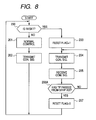
- the voltage regulator 4 can be modified to perform, instead of the process shown in FIG. 6 , a process shown in FIG. 8 .
- step 206 of FIG. 6 differs from the process of FIG. 6 only in that step 206 of FIG. 6 is replaced with step 206A in FIG. 8 .
- step 206A a determination is made as to whether a predetermined time period TP has passed from step 203.
- the voltage regulator 4 cyclically transmits the condition signal which represents the value "1" of the reset flag for the predetermined time period TP (i.e., steps 204, 205, and 206A), and then sets the value of reset flag to "0".
- the cycle Tc in which the condition signal is transmitted, is less than a half of the time consonant of the field current supplied to the field coil 3A of the alternator 3.
- the predetermined time period Tp, for which the condition signal is cyclically transmitted is longer than at least twice the cycle Tc.
- the ECU 1 can detect the occurrence rate of reset for the power generation control circuit 30.
- the fault conditions may include, for example, conditions where the noises imposed on the charge line 43 change with the rotational speed of the engine or great voltage ripples occur due to a disconnection of the charge line 43 from the battery 5.
- the ECU 1 will receive the condition signal transmitted from the voltage regulator 4 10 times.
- the ECU 1 will receive the condition signal less than 10 times; this is because the voltage regulator 4 cannot transmit the condition signal during the resets of the power generation control circuit 30. Accordingly, the ECU 1 can detect the occurrence rate of reset for the power generation control circuit 30 on the basis of the number of times it receives the condition signal transmitted from the voltage regulator 4.
- the ECU 1 can detect the fault conditions and optimally determine the command signal (more specifically, the command values for the power generation control parameters).
- the previous embodiment is directed to the automotive power generation system S1
- the invention also can be applied to other control apparatus for electric generators and electric power generation systems.
Landscapes
- Engineering & Computer Science (AREA)
- Power Engineering (AREA)
- Control Of Eletrric Generators (AREA)
- Control Of Charge By Means Of Generators (AREA)
Abstract
Description
- This application is based on and claims priority from
Japanese Patent Application No. 2007 - 19078, filed on January 30, 2007 - The present invention relates generally to control apparatus for electric generators and electric power generation systems.
- More particularly, the invention relates to a control apparatus for an automotive alternator, which can reliably inform a reset thereof to an engine control unit (ECU), and an automotive power generation system that includes such a control apparatus. 2 Description of the Related Art
- A conventional power generation system for a motor vehicle, such as the one disclosed in
U.S. Patent No. 5767636 , includes an automotive alternator, a voltage regulator for regulating the output voltage of the alternator, and an ECU that communicates with the voltage regulator for controlling power generation of the alternator. More specifically, the ECU sends to the voltage regulator a command signal that represents command values for power generation control parameters; the voltage regulator regulates the output voltage of the alternator according to the command signal. With such a configuration, it is possible to suitably control the power generation of the alternator according to the operating condition of the engine. - Moreover, the alternator is generally installed in an engine compartment and supplies electric power to both a battery and electric loads via a charge line. The alternator also supplies power to the voltage regulator which is generally built in the alternator.
- Furthermore, the voltage regulator may be falsely reset due to various noises imposed on the power lines of the power generation system. For example, on the power lines, ignition noises may be imposed in the case of the engine being a gasoline engine; power noises may be imposed when the alternator drives an inductive load, such as a motor; great voltage ripples may be imposed when the power generation system operates without the battery.
- When the voltage regulator is reset, all the command values for the power generation control parameters having been sent from the ECU to the voltage regulator are initialized. However, since the ECU cannot be aware of the initialization of those command values, it continues its control on the power generation of the alternator on the assumption that those command values are still effective in the voltage regulator. As a result, malfunctions will be caused in performing a stabilization control of the output voltage of the alternator, a fuel economy-improving control, or a stabilization control of idle rotation. Furthermore, when the command values for the power generation control parameters are incorrectly initialized in the reset of the voltage regulator caused by the noises, the voltage regulator can no longer suitably control the alternator; however, the ECU cannot be aware of such a wrong condition of the voltage regulator.
- The present invention has been made in view of the above-mentioned problems.
- It is, therefore, one object of the present invention to provide a control apparatus for an automotive alternator, which can reliably inform a reset thereof to an external control apparatus that communicates with the control apparatus for controlling power generation of the alternator.
- It is another object of the present invention to provide an automotive power generation system, in which a first control apparatus can reliably inform a reset thereof to a second control apparatus that communicates with the first control apparatus for controlling power generation of an automotive alternator.
- According to one aspect of the present invention, there is provided a control apparatus which controls power generation of an electric generator and communicates with an external control apparatus. The control apparatus includes: a control circuit that controls the power generation of the electric generator according to a command signal transmitted from the external control apparatus; means for reseting the control circuit; and means for informing the external control apparatus of a power generation condition of the electric generator by transmitting a condition signal, the condition signal indicating both the power generation condition of the electric generator and information on whether a reset of the control circuit is made by the reseting means.
- With the above configuration, when the control circuit is reset due to, for example, noises, the control apparatus can reliably inform the external control apparatus of the reset of the control circuit.
- According to a further implementation, the informing means transmits the condition signal in a cycle of less than a half of a time consonant of field current supplied to the electric generator.
- Specifying the cycle as above, it is possible for the control apparatus to inform a reset of the control circuit before a great change in the power generation of the electric generator takes place due to the reset.
- Further, when a reset of the control circuit is made by the resetting means, the informing means sets a reset flag to a first value, cyclically transmits for a predetermined time period the condition signal which represents the first value of the reset flag, and then sets the reset flag to a second value, the first value of the reset flag indicating that a reset of the control circuit is made, the second value of the reset flag indicating that no reset of the control circuit is made, the predetermined time period being longer than at least twice the cycle in which the condition signal is transmitted.
- Specifying the predetermined time period as above, when the control circuit is repeatedly reset in some fault conditions, the external control apparatus can detect the occurrence rate of reset for the control circuit. Consequently, on the basis of the occurrence rate of reset, the external control apparatus can detect the fault conditions and optimally determine the command signal.
- Moreover, in the above control apparatus, the command signal may represent command values for power generation control parameters, and the condition signal may represent actual values of the power generation control parameters. The power generation control parameters may include an output voltage of the electric generator, field current supplied to the electric generator, and a duty of a power transistor for controlling the field current. The electric generator may be an automotive alternator; the control apparatus may be a voltage regulator for regulating an output voltage of the automotive alternator; the external control apparatus may be an engine control unit.
- According to another aspect of the present invention, there is provided an electric power generation system which includes an electric generator, and first and second control apparatus that communicate with each other to control power generation of the electric generator. The first control apparatus includes: a control circuit that controls the power generation of the electric generator according to a command signal transmitted from the second control apparatus; means for reseting the control circuit; and means for informing the second control apparatus of a power generation condition of the electric generator by transmitting a condition signal, the condition signal indicating both the power generation condition of the electric generator and information on whether a reset of the control circuit is made by the reseting means. The second control apparatus determines whether a reset of the control circuit of the first control apparatus is made on the basis of the condition signal transmitted from the first control apparatus.
- With the above configuration, when the control circuit is reset due to, for example, noises, the first control apparatus can reliably inform the second control apparatus of the reset of the control circuit.
- According to a further implementation, when it is determined that a reset of the control circuit of the first control apparatus is made, the second control circuit transmits the command signal to the first control circuit.
- With the above configuration, when the command signal is lost in the first control apparatus due to the reset, it is still possible for the first control apparatus to immediately resume a suitable control on the power generation of the electric generator according to the command signal transmitted by the second control apparatus.
- Further, when a reset of the control circuit is made by the resetting means, the informing means of the first control apparatus sets a reset flag to a first value, transmits to the second control apparatus the condition signal which represents the first value of the reset flag, and then sets the reset flag to a second value upon safe receipt of the command signal which is transmitted by the second control apparatus in response to the condition signal, the first value of the reset flag indicating that a reset of the control circuit is made, the second value of the reset flag indicating that no reset of the control circuit is made.
- With the above configuration, the first control apparatus can be prevented from further informing the second control apparatus of the reset of the control circuit after the safe receipt of the command signal.
- Moreover, in the above electric power generation system, the command signal may represent command values for power generation control parameters, and the condition signal may represent actual values of the power generation control parameters. The power generation control parameters may include an output voltage of the electric generator, field current supplied to the electric generator, and a duty of a power transistor for controlling the field current. The electric power generation system may be for use in a motor vehicle with the electric generator being an automotive alternator, the first control apparatus being a voltage regulator for regulating an output voltage of the automotive alternator, and the second control apparatus being an engine control unit for controlling an engine of the vehicle.
- The present invention will be understood more fully from the detailed description given hereinafter and from the accompanying drawings of one preferred embodiment of the invention, which, however, should not be taken to limit the invention to the specific embodiment but are for the purpose of explanation and understanding only.
- In the accompanying drawings:
-
FIG. 1 is a schematic diagram showing the overall configuration of an automotive power generation system according to an embodiment of the invention; -
FIG. 2 is a functional block diagram showing the detailed configuration of an ECU and a voltage regulator in the power generation system; -
FIG. 3 is a schematic diagram illustrating a digital format of a condition signal that is transmitted from the voltage regulator to the ECU via a serial communication according to LIN protocol; -
FIG. 4 is a schematic diagram illustrating a digital format of a command signal that is transmitted from the ECU to the voltage regulator via the serial communication; -
FIG. 5 is a flow chart illustrating a process of the ECU for controlling the power generation of an automotive alternator in cooperation with the voltage regulator; -
Fig. 6 is a flow chart illustrating a process of the voltage regulator for controlling the power generation of the alternator in cooperation with the ECU; -
FIG. 7 is a schematic view illustrating a sequence of the serial communication between the ECU and alternator; and -
FIG. 8 is a flow chart illustrating a variation of the process ofFIG. 6 . - One preferred embodiment of the present invention will be described hereinafter with reference to
FIGS. 1 - 7 . -
FIG. 1 shows the overall configuration of an automotive power generation system S1 according to the present embodiment. As shown, the power generation system S1 includes an Engine Control Unit (ECU) 1, anengine 2, an automotive alternator (abbreviated to ALT inFIG.1 ) 3, avoltage regulator 4, a battery (abbreviated to BATT inFIG.1 ) 5, a motor 6, andelectric loads 7. - The ECU 1 controls the output of the
engine 2 on the basis of sensing signals output from various sensors for sensing the running condition of a vehicle driven by theengine 2. TheECU 1 also functions as an external control apparatus to the alternator 3. - The alternator 3 is driven by the
engine 2 via abelt 23. The electric power generated by the alternator 3 is used to charge thebattery 5 and power the motor 6 andelectric loads 7. More specifically, an output terminal of the alternator 3 is electrically connected to a positive terminal of thebattery 5 via acharge line 43; both the motor 6 andelectric loads 7 are connected to thecharge line 43 via respective switches. In addition, theengine 2 includes a plurality ofignition devices 2A, each of which is powered by thebattery 5 to ignite the air/fuel mixture in a corresponding a cylinder of theengine 2. - The
voltage regulator 4, which is built in the alternator 3 in the present embodiment, regulates the output voltage of alternator 3 by controlling field current supply to the alternator 3. -
FIG. 2 shows the detailed configuration of theECU 1 andvoltage regulator 4. As shown, thevoltage regulator 4 includes apower transistor 11, a free-wheelingdiode 12, ananalog circuit 20, a power generation control circuit (abbreviated to P.G.C.C. inFIG. 2 ) 30, adriver 40, apower circuit 50, and areset circuit 52. - The
power transistor 11 is connected in series with afield coil 3A of the alternator 3, so that thefield coil 3A can be supplied with field current when thepower transistor 11 is turned on. More specifically, thepower transistor 11 has its drain connected to the output terminal of the alternator 3 and its source connected to thefield coil 3A. - The free-wheeling
diode 12 is connected in parallel with thefield coil 3A, so that the electric energy stored in thefield coil 3A can be removed from thefield coil 3A when thepower transistor 11 is turned off. More specifically, the free-wheelingdiode 12 has its cathode connected to the source of thepower transistor 11 and its anode grounded. - The
analog circuit 20 has both a function of detecting the power generating condition of the alternator 3 and a function of driving thepower transistor 11 by sending a drive signal to the gate of thepower transistor 11. The power generating condition of the alternator 3 is represented by actual values of power generation control parameters, such as the output voltage of the alternator 3, the field current supplied to thefield coil 3A, and the duty of thepower transistor 11. To this end, though not shown inFIG. 2 , theanalog circuit 20 includes a driver for driving thepower transistor 11, an analog control circuit for controlling the driver, and detecting circuits for respectively detecting the output voltage of the alternator 3, the field current supplied to thefield coil 3A, and the duty of thepower transistor 11. Moreover, the analog control circuit is controlled by the powergeneration control circuit 30. - The power
generation control circuit 30 has both a function of controlling the power generation of the alternator 3 according to a command signal sent from theECU 1 and a function of sending to the ECU 1 a condition signal that indicates the power generating condition of the alternator 3. The command signal represents command values for the power generation control parameters, whereas the condition signal represents the actual values of the power generation control parameters detected by theanalog circuit 20. To this end, as shown inFIG. 2 , the powergeneration control circuit 30 includes adigital circuit 32, acondition signal storage 34 in which the condition signal (i.e., the actual values of the power generation control parameters) is stored, acommunication controller 36, and acommand signal storage 38 in which the command signal (i.e., the command values for the power generation control parameters) is stored. - The
digital circuit 32 generates the condition signal on the basis of the actual values of the power generation control parameters detected by theanalog circuit 20. The generated condition signal is then stored in thecondition signal storage 34. Thedigital circuit 32 also has a power generation control function which is to be described in detail later. -
FIG. 3 shows a digital format of the condition signal that is transmitted from thevoltage regulator 4 to theECU 1 via a serial communication according to the LIN protocol. - As shown in
FIG. 3 , the condition signal includes, after the sync field and transmission ID field, a voltage response field, a field current response field, a duty response field, a diagnostic information field, and a check data field. - The transmission ID field contains an identifier which is assigned according to a transmission request from the
ECU 1 and has a value set according to the transmission request. - The voltage response field contains response data representing the actual value of the output voltage of the alternator 3 which is detected by the
analog circuit 20. - The field current response field contains response data representing the actual value of the field current supplied to the
field coil 3A which is detected by theanalog circuit 20. - The duty response field contains response data representing the actual value of the duty of the
power transistor 11 which is detected by theanalog circuit 20. - The diagnostic information field contains response data of predetermined bits representing diagnostic information. In the present embodiment, the head bit of the diagnostic information field is used for a reset flag which is described in detail later.
- The check data field contains data for check, such as parity and CRC data.
- Referring again to
FIG. 2 , thecommunication controller 36 of the powergeneration control circuit 30 has a function of modulating the condition signal stored in thecondition signal storage 34 into the digital format shown inFIG. 3 . - The
driver 40 functions both as a transmitter to transmit the modulated condition signal to theECU 1 via acommunication line 80 and as a receiver to receive a modulated command signal from theECU 1 via thecommunication line 80. - In addition, the above-described
communication controller 36 also has a function of demodulating the modulated command signal received by thedriver 40. The command signal demodulated by thecommunication controller 36 is then stored in thecommand signal storage 38. -
FIG. 4 shows a digital format of the command signal that is transmitted from theECU 1 to thevoltage regulator 4 via the serial communication according to the LIN protocol. - As shown in
FIG. 4 , the command signal includes, after the sync filed and reception ID field, a voltage command field, a field current command field, an LRC field, a vehicle information field, and a check data field. - The voltage command field contains command data representing the target value of the output voltage of the alternator 3.
- The field current command field contains command data representing limit values of the field current supplied to the
field coil 3A. - The LRC field contains command data representing limit values of changes in the field current supplied to the
field coil 3A and in the duty of thepower transistor 11 when the total load of the alternator 3 (i.e., the motor 6 plus the electric loads 7) changes rapidly. - Turning back to
FIG. 2 , thedigital circuit 32 controls, via theanalog circuit 20, the power generation of the alternator 3 according to the command signal stored in thecommand signal storage 38. For example, in one control mode, thedigital circuit 32 controls theanalog circuit 20 to drive thepower transistor 11 so as to bring the actual value of the output voltage detected by theanalog circuit 20 into agreement with the target value of the output voltage indicated by the command signal. In another control mode, thedigital circuit 32 controls theanalog circuit 20 to drive thepower transistor 11 so as to limit the actual value of the field current detected by theanalog circuit 20 within the limit values of the field current indicated by the command signal. In yet another control mode, thedigital circuit 32 controls theanalog circuit 20 to drive thepower transistor 11 so as to limit the changes in the actual values of the field current and duty of thepower transistor 11 detected by theanalog circuit 20 within the respective limit values of those changes indicated by the command signal. - The
power circuit 50 serves to supply electric power to each component of thevoltage regulator 4. - The
reset circuit 52 resets the powergeneration control circuit 30 at predetermined timings. For example, the reset operation of thereset circuit 52 is generally made when thevoltage regulator 4 is activated. However, the reset operation also may be falsely made when great ignition noises are induced in sync with the ignition timings of theignition devices 2A and transmitted to thevoltage regulator 4 via the output terminal of the alternator 3. In the reset operation, thereset circuit 52 sends a reset signal to the powergeneration control circuit 30. Upon receipt of the reset signal, the powergeneration control circuit 30 is reset, so that the command signal (i.e., the command values) stored in thecommand signal storage 38 is initialized. After the reset of the powergeneration control circuit 30, thedigital circuit 32 sets to "1" the value of the reset flag which is the head bit of the condition signal stored in thecondition signal storage 34. - The
ECU 1 includes, as shown inFIG. 2 , amicrocomputer 60, A/D converters command signal storage 70 in which the command signal (i.e., the command values for the power generation control parameters) is stored, acommunication controller 72, adriver 74, and acondition signal storage 76 in which the condition signal (i.e., the actual values of the power generation control parameters) is stored. - The
microcomputer 60 adjusts, for example, the fuel injection quantities of theengine 2 and the ignition timings of theignition devices 2A on the basis of the sensing signals input via the A/D converters engine 2. The sensing signals are output from various sensors, such as a vehicle speed sensor, a throttle sensor, and an 02 sensor. Further, themicrocomputer 60 generates the command signal according to the operating condition of theengine 2. The generated command single is then stored in thecommand signal storage 70. - The
communication controller 72 has a function of modulating the command signal stored in thecommand signal storage 70 into the digital format shown inFIG. 4 . - The
driver 74 functions both as a transmitter to transit the modulated command signal to thevoltage regulator 4 via thecommunication line 80 and as a receiver to receive the modulated condition signal from thevoltage regulator 4 via thecommunication line 80. - In addition, the above-described
communication controller 72 also has a function of demodulating the modulated condition signal received by thedriver 74. The condition signal demodulated by thecommunication controller 72 is then stored in the conditionsingle storage 76 and further used by themicrocomputer 60 to control theengine 2. - In the present embodiment, the
reset circuit 52 makes up means for resetting the powergeneration control circuit 30; thedigital circuit 32,condition signal storage 34,communication controller 36, anddriver 40 together make up means for informing theECU 1 of a reset of the power generation control circuit. - After having described the configurations of the
ECU 1 andvoltage regulator 4 according to the present embodiment, operations thereof will be described hereinafter. -
FIG. 5 shows a process of theECU 1 for controlling the power generation of the alternator 3 in cooperation with thevoltage regulator 4. - First, at
step 100, theECU 1 receives the condition signal transmitted by thevoltage regulator 4. - At
step 101, the ECU 1 (more specifically, themicrocomputer 60 thereof) determines whether or not the reset flag is included in the condition signal. - If the determination at
step 101 produces a "NO" answer, then the process proceeds to step 102, at which theECU 1 determines a failure in resetting the powergeneration control circuit 30 of thevoltage regulator 4 and performs necessary processes. - For example, when the condition signal transmitted from the
voltage regulator 4 includes no diagnostic information field, the determination atstep 101 will produce a "NO" answer. In this case, theECU 1 determines that a reset of the powergeneration control circuit 30 of thevoltage regulator 4 has failed and takes necessary steps. - On the contrary, if the determination at
step 101 produces a "YES" answer, then the process goes on to step 103, at which theECU 1 transmits to thevoltage regulator 4 the command signal that indicates the command values for the power generation control parameters. - After that, at
step 104, theECU 1 receives again the condition signal (more precisely, the next condition signal). - At
step 105, theECU 1 determines whether or not the value of the reset flag in the condition signal received at step S104 is equal to "1". - If the determination at
step 105 produces a "NO" answer, then the process proceeds to step 106, at which theECU 1 performs its normal control on the power generation of the alternator 3. Thereafter, the process returns to step 104 to repeat the subsequent steps. - More specifically, in this case, the
ECU 1 determines that no reset of the powergeneration control circuit 30 of thevoltage regulator 4 has been made in the present cycle, and thus does not send to thevoltage regulator 4 the command values for the power generation control parameters. - On the contrary, if the determination at
step 105 produces a "YES" answer, then the process goes on to step 107, at which theECU 1 transmits the command signal to thevoltage regulator 4. Then, the process returns to step 104 to repeat the subsequent steps. - More specifically, in this case, the
ECU 1 determines that a reset of the powergeneration control circuit 30 of thevoltage regulator 4 has been made in the present cycle, and thus sends to thevoltage regulator 4 the command values for the power generation control parameters by transmitting the command signal. -
FIG. 6 shows a process of thevoltage regulator 4 for controlling the power generation of the alternator 3 in cooperation with theECU 1. - First, at
step 200, the voltage regulator 4 (More specifically, thedigital circuit 32 thereof) determines whether a reset of the powergeneration control circuit 30 has been made in the present cycle. - If the determination at
step 200 produces a "NO" answer, then the process proceeds to step 201, at which thevoltage regulator 4 performs its normal control on the power generation of the alternator 3. - More specifically, at
step 201, thedigital circuit 32 controls the power generation of the alternator 3 according to the command signal stored in thecommand signal storage 38; thedigital circuit 32 also generates the condition signal which represents the actual values of the power generation control parameters most recently detected by theanalog circuit 20 and the value of the reset flag being equal to "0". - At succeeding
step 202, thevoltage regulator 4 transmits to theECU 1 the condition signal generated atstep 201. Then, the process returns to step 200 to repeat the subsequent steps. - On the contrary, if the determination at
step 200 produces a "YES" answer, then the process goes on to step 203, at which the value of the reset flag is set to "1". - More specifically, at
step 203, thedigital circuit 32 generates the condition signal which represents the actual values of the power generation control parameters most recently detected by theanalog circuit 20 and the value of the reset flag being equal to "1". - At succeeding
step 204, thevoltage regulator 4 transmits to theECU 1 the condition signal generated atstep 203. - At
step 205, thevoltage regulator 4 receives the command signal that is transmitted by theECU 1 in response to the condition signal transmitted atstep 204. - At
step 206, thevoltage regulator 4 determines whether the command signal has been safely received atstep 205. - If the determination at
step 206 produces a "NO" answer, then the process returns to step 204 to repeat the subsequent steps. - On the contrary, if the determination at
step 206 produces a "YES" answer, then the process proceeds to step 207. - At
step 207, thevoltage regulator 4 sets to "0" the value of the reset flag in the condition signal stored in thecondition signal storage 34. Then, the process returns to step 200 to repeat the subsequent steps. -
FIG. 7 shows a sequence of the serial communication between theECU 1 andvoltage regulator 4. - As shown in
FIG. 7 , before completion of the nth transmission of the command signal by theECU 1, the command values for the power generation control parameters stored in thecommand signal storage 38 of thevoltage regulator 4 are those values which are obtained through the (n-1)th transmission of the command signal by theECU 1. - After completion of the nth transmission of the command signal by the
ECU 1, i.e., after completion of the nth reception of the command signal by thevoltage regulator 4, the command values stored in thecommand signal storage 38 are those values which are obtained through the nth transmission of the command signal. - Moreover, at this stage, the value of the reset flag in the condition signal transmitted from the
voltage regulator 4 to theECU 1 is equal to "0". - When a reset of the power generation control circuit (abbreviated to P.G.C.C. in
FIG. 7 ) 30 of thevoltage regulator 4 is made due to noises, the command values stored in thecommand signal storage 38 are initialized to default values. - Then, the
voltage regulator 4 transmits to theECU 1 the condition signal which represents the value of the reset flag being equal to "1". Upon receipt of the condition signal, theECU 1 conducts the (n+1)th transmission of the command signal. - After completion of the (n+1)th transmission of the command signal by the
ECU 1, i.e., after completion of the (n+1)th reception of the command signal by thevoltage regulator 4, the default values in thecommand signal storage 38 are overwritten with the command values which are obtained through the (n+1) transmission of the command signal. - As above, in the automotive power
generation system S 1 according to the present embodiment, when the powergeneration control circuit 30 is reset due to noises imposed on thecharge line 43, thevoltage regulator 4 can reliably inform theECU 1 of the reset of the powergeneration control circuit 30. - Further, upon being informed of the reset of the power
generation control circuit 30, theECU 1 immediately transmits to thevoltage regulator 4 the command signal that represents the command values for the power generation control parameters. Therefore, though the command values stored in the powergeneration control circuit 30 were initialized during the reset, it is still possible for thevoltage regulator 4 to immediately resume a suitable control on the power generation of the alternator 3 according to the command signal transmitted by theECU 1. - Furthermore, when the reset of the power
generation control circuit 30 is made, thevoltage regulator 4 sets the value of the reset flag to "1", transmits to theECU 1 the condition signal which represents the value "1" of the reset flag, and then sets the reset flag to "0" upon safe receipt of the command signal which is transmitted by theECU 1 in response to the condition signal. - With the above configuration, the
voltage regulator 4 can be prevented from further informing theECU 1 of the reset of the powergeneration control circuit 30 after the safe receipt of the command signal. - While the above particular embodiment of the present invention has been shown and described, it will be understood by those skilled in the art that various modifications, changes, and improvements may be made without departing from the spirit of the invention.
- For example, the
voltage regulator 4 can be modified to perform, instead of the process shown inFIG. 6 , a process shown inFIG. 8 . - The process of
FIG. 8 differs from the process ofFIG. 6 only in thatstep 206 ofFIG. 6 is replaced withstep 206A inFIG. 8 . Atstep 206A, a determination is made as to whether a predetermined time period TP has passed fromstep 203. - More specifically, according to the process of
FIG. 8 , thevoltage regulator 4 cyclically transmits the condition signal which represents the value "1" of the reset flag for the predetermined time period TP (i.e., steps 204, 205, and 206A), and then sets the value of reset flag to "0". - Further, the cycle Tc, in which the condition signal is transmitted, is less than a half of the time consonant of the field current supplied to the
field coil 3A of the alternator 3. - Specifying the cycle Tc as above, it is possible for the
voltage regulator 4 to inform a reset of the powergeneration control circuit 30 before a great change in the power generation of the alternator 3 takes place due to the reset. - Furthermore, the predetermined time period Tp, for which the condition signal is cyclically transmitted, is longer than at least twice the cycle Tc.
- Specifying Tp as above, when the power
generation control circuit 30 is repeatedly reset in some fault conditions, theECU 1 can detect the occurrence rate of reset for the powergeneration control circuit 30. The fault conditions may include, for example, conditions where the noises imposed on thecharge line 43 change with the rotational speed of the engine or great voltage ripples occur due to a disconnection of thecharge line 43 from thebattery 5. - More specifically, suppose that the cycle Tc is 20 ms and the predetermined time period Tp is 200 ms. Then, when no further reset of the power
generation control circuit 30 is made for the predetermined time period Tp, theECU 1 will receive the condition signal transmitted from thevoltage regulator 4 10 times. On the contrary, when further resets are made for the predetermined time period Tp, theECU 1 will receive the condition signal less than 10 times; this is because thevoltage regulator 4 cannot transmit the condition signal during the resets of the powergeneration control circuit 30. Accordingly, theECU 1 can detect the occurrence rate of reset for the powergeneration control circuit 30 on the basis of the number of times it receives the condition signal transmitted from thevoltage regulator 4. - Consequently, on the basis of the occurrence rate of reset, the
ECU 1 can detect the fault conditions and optimally determine the command signal (more specifically, the command values for the power generation control parameters). - Moreover, although the previous embodiment is directed to the automotive power generation system S1, the invention also can be applied to other control apparatus for electric generators and electric power generation systems.
Claims (12)
- A control apparatus which controls power generation of an electric generator and communicates with an external control apparatus, the control apparatus comprising:a control circuit that controls the power generation of the electric generator according to a command signal transmitted from the external control apparatus;means for reseting the control circuit; andmeans for informing the external control apparatus of a power generation condition of the electric generator by transmitting a condition signal, the condition signal indicating both the power generation condition of the electric generator and information on whether a reset of the control circuit is made by the reseting means.
- The control apparatus as set forth in Claim 1, wherein the informing means transmits the condition signal in a cycle of less than a half of a time consonant of field current supplied to the electric generator.
- The control apparatus as set forth in Claim 2,
wherein when a reset of the control circuit is made by the resetting means, the informing means sets a reset flag to a first value, cyclically transmits for a predetermined time period the condition signal which represents the first value of the reset flag, and then sets the reset flag to a second value, the first value of the reset flag indicating that a reset of the control circuit is made, the second value of the reset flag indicating that no reset of the control circuit is made, the predetermined time period being longer than at least twice the cycle in which the condition signal is transmitted. - The control apparatus as set forth in Claim 1, wherein the command signal represents command values for power generation control parameters, and the condition signal represents actual values of the power generation control parameters.
- The control apparatus as set forth in Claim 4,
wherein the power generation control parameters include an output voltage of the electric generator, field current supplied to the electric generator, and a duty of a power transistor for controlling the field current. - The control apparatus as set forth in Claim 1,
wherein the electric generator is an automotive alternator, the control apparatus is a voltage regulator for regulating an output voltage of the automotive alternator, and the external control apparatus is an engine control unit. - An electric power generation system comprising:an electric generator; andfirst and second control apparatus that communicate with each other to control power generation of the electric generator,whereinthe first control apparatus comprises:a control circuit that controls the power generation of the electric generator according to a command signal transmitted from the second control apparatus;means for reseting the control circuit; andmeans for informing the second control apparatus of a power generation condition of the electric generator by transmitting a condition signal, the condition signal indicating both the power generation condition of the electric generator and information on whether a reset of the control circuit is made by the reseting means, andwhereinthe second control apparatus determines whether a reset of the control circuit of the first control apparatus is made on the basis of the condition signal transmitted from the first control apparatus.
- The electric power generation system as set forth in Claim 7, wherein when it is determined that a reset of the control circuit of the first control apparatus is made, the second control circuit transmits the command signal to the first control circuit.
- The electric power generation system as set forth in Claim 8, wherein when a reset of the control circuit is made by the resetting means, the informing means of the first control apparatus sets a reset flag to a first value, transmits to the second control apparatus the condition signal which represents the first value of the reset flag, and then sets the reset flag to a second value upon safe receipt of the command signal which is transmitted by the second control apparatus in response to the condition signal, the first value of the reset flag indicating that a reset of the control circuit is made, the second value of the reset flag indicating that no reset of the control circuit is made.
- The electric power generation system as set forth in Claim 7, wherein the command signal represents command values for power generation control parameters, and the condition signal represents actual values of the power generation control parameters.
- The electric power generation system as set forth in Claim 10, wherein the power generation control parameters include an output voltage of the electric generator, field current supplied to the electric generator, and a duty of a power transistor for controlling the field current.
- The electric power generation system as set forth in Claim 7, wherein the electric power generation system is for use in a motor vehicle with the electric generator being an automotive alternator, the first control apparatus being a voltage regulator for regulating an output voltage of the automotive alternator, and the second control apparatus being an engine control unit for controlling an engine of the vehicle.
Applications Claiming Priority (1)
| Application Number | Priority Date | Filing Date | Title |
|---|---|---|---|
| JP2007019078A JP4281805B2 (en) | 2007-01-30 | 2007-01-30 | Vehicle power generation control device and vehicle power generation system |
Publications (3)
| Publication Number | Publication Date |
|---|---|
| EP1953911A2 true EP1953911A2 (en) | 2008-08-06 |
| EP1953911A3 EP1953911A3 (en) | 2010-06-16 |
| EP1953911B1 EP1953911B1 (en) | 2014-11-12 |
Family
ID=39427731
Family Applications (1)
| Application Number | Title | Priority Date | Filing Date |
|---|---|---|---|
| EP08001429.3A Ceased EP1953911B1 (en) | 2007-01-30 | 2008-01-25 | Control apparatus for automotive alternator and automotive power generation system |
Country Status (3)
| Country | Link |
|---|---|
| US (1) | US7948216B2 (en) |
| EP (1) | EP1953911B1 (en) |
| JP (1) | JP4281805B2 (en) |
Families Citing this family (2)
| Publication number | Priority date | Publication date | Assignee | Title |
|---|---|---|---|---|
| DE102012204918A1 (en) * | 2012-03-27 | 2013-10-02 | Robert Bosch Gmbh | Method for activating e.g. asynchronous operation function in hybrid vehicle, involves deactivating functions if state variable comprises ground state, and activating functions if state variable comprises ground state |
| US9929685B2 (en) * | 2015-06-10 | 2018-03-27 | Infineon Technologies Ag | Safety circuit and brush holder for preventing fault conditions in an alternator |
Citations (2)
| Publication number | Priority date | Publication date | Assignee | Title |
|---|---|---|---|---|
| US5767636A (en) | 1995-01-31 | 1998-06-16 | Nippondenso Co., Ltd. | Vehicle power generating apparatus |
| JP2007019078A (en) | 2005-07-05 | 2007-01-25 | Shindo Denshi Kogyo Kk | Printed circuit board, flexible printed circuit board, and manufacturing method thereof |
Family Cites Families (35)
| Publication number | Priority date | Publication date | Assignee | Title |
|---|---|---|---|---|
| US4701588A (en) * | 1984-02-09 | 1987-10-20 | Sanyo Electric Co., Ltd. | Oscillation control circuit of an induction heating apparatus |
| JP3102981B2 (en) * | 1993-12-28 | 2000-10-23 | 三菱電機株式会社 | Output control device for vehicle alternator |
| JP3214224B2 (en) * | 1994-04-22 | 2001-10-02 | 株式会社日立製作所 | Vehicle generator |
| JP3565613B2 (en) * | 1995-03-20 | 2004-09-15 | 株式会社ルネサステクノロジ | Semiconductor integrated circuit device |
| US6137247A (en) * | 1997-12-08 | 2000-10-24 | Denso Corporation | Electric power generation control for vehicles using a plurality of control signals |
| JP3509007B2 (en) * | 2000-06-29 | 2004-03-22 | 株式会社デンソー | AC generator for vehicles |
| US6366064B1 (en) * | 2000-09-29 | 2002-04-02 | American Superconductor Corporation | Dual mode controller for switching circuirty |
| JP3624821B2 (en) * | 2000-11-22 | 2005-03-02 | 日産自動車株式会社 | Vehicle control device |
| JP4239402B2 (en) | 2000-11-30 | 2009-03-18 | 株式会社デンソー | Vehicle power generation control device |
| JP4438260B2 (en) * | 2001-08-30 | 2010-03-24 | 株式会社デンソー | Vehicle power generation control device |
| JP4001072B2 (en) * | 2003-01-29 | 2007-10-31 | 株式会社デンソー | Vehicle power generation system |
| JP4061238B2 (en) * | 2003-05-07 | 2008-03-12 | 三菱電機株式会社 | Control device and control method for vehicle generator |
| JP4166669B2 (en) * | 2003-10-28 | 2008-10-15 | 三菱電機株式会社 | Vehicle power control device |
| JP3997987B2 (en) * | 2003-12-25 | 2007-10-24 | 株式会社デンソー | Power generation control system |
| US7446518B2 (en) * | 2004-03-08 | 2008-11-04 | Semtech Corporation | Method and apparatus for enhancing voltage regulator transient response |
| JP4182957B2 (en) * | 2004-07-06 | 2008-11-19 | 株式会社デンソー | Power generation control device |
| WO2006046372A1 (en) * | 2004-10-29 | 2006-05-04 | Rohm Co., Ltd | Switching regulator control circuit, switching regulator using the circuit, and switching signal generating apparatus |
| JP4189765B2 (en) * | 2005-03-23 | 2008-12-03 | 株式会社デンソー | Power generation control device |
| JP4182954B2 (en) | 2005-04-12 | 2008-11-19 | 株式会社デンソー | Vehicle power generation control device |
| JP4017637B2 (en) * | 2005-04-21 | 2007-12-05 | 三菱電機株式会社 | Control device for vehicle generator |
| JP2007043825A (en) * | 2005-08-03 | 2007-02-15 | Denso Corp | Vehicle power generation control device |
| US7777460B2 (en) * | 2005-09-16 | 2010-08-17 | International Rectifier Corporation | Multi-phase converter with improved current sharing |
| JP4497077B2 (en) * | 2005-10-17 | 2010-07-07 | 株式会社デンソー | Power generation abnormality monitoring system |
| JP4969943B2 (en) * | 2006-08-10 | 2012-07-04 | 株式会社デンソー | Battery charge / discharge current detector |
| JP4595933B2 (en) * | 2006-12-12 | 2010-12-08 | 株式会社デンソー | Battery current detection device for vehicle |
| US8016433B2 (en) * | 2007-03-09 | 2011-09-13 | Sony Corporation | Projector and control method thereof |
| TWI343694B (en) * | 2007-12-31 | 2011-06-11 | Fitipower Integrated Tech Inc | Voltage converter |
| US9059632B2 (en) * | 2008-03-24 | 2015-06-16 | O2Micro, Inc. | Controllers for DC to DC converters |
| US7777469B2 (en) * | 2008-07-01 | 2010-08-17 | International Rectifier Corporation | Converter having PWM ramp adjustable in discontinuous mode operation |
| TWI401695B (en) * | 2009-01-23 | 2013-07-11 | Nanya Technology Corp | Signal adjusting system and signal adjusting method |
| US7973523B2 (en) * | 2009-02-02 | 2011-07-05 | Texas Instruments Incorporated | Reverse current sensing regulator system and method |
| CN101856912B (en) * | 2009-04-01 | 2013-05-22 | 精工爱普生株式会社 | Memory device and system including memory device electronically connectable to host circuit |
| EP2237163B1 (en) * | 2009-04-01 | 2013-05-01 | Seiko Epson Corporation | System having a plurality of memory devices and data transfer method for the same |
| JP2010267341A (en) * | 2009-05-15 | 2010-11-25 | Renesas Electronics Corp | Semiconductor device |
| JP5458825B2 (en) * | 2009-07-10 | 2014-04-02 | 富士通株式会社 | Voltage regulator circuit |
-
2007
- 2007-01-30 JP JP2007019078A patent/JP4281805B2/en active Active
-
2008
- 2008-01-25 EP EP08001429.3A patent/EP1953911B1/en not_active Ceased
- 2008-01-28 US US12/010,631 patent/US7948216B2/en not_active Expired - Fee Related
Patent Citations (2)
| Publication number | Priority date | Publication date | Assignee | Title |
|---|---|---|---|---|
| US5767636A (en) | 1995-01-31 | 1998-06-16 | Nippondenso Co., Ltd. | Vehicle power generating apparatus |
| JP2007019078A (en) | 2005-07-05 | 2007-01-25 | Shindo Denshi Kogyo Kk | Printed circuit board, flexible printed circuit board, and manufacturing method thereof |
Also Published As
| Publication number | Publication date |
|---|---|
| JP2008184021A (en) | 2008-08-14 |
| US20080179890A1 (en) | 2008-07-31 |
| EP1953911B1 (en) | 2014-11-12 |
| JP4281805B2 (en) | 2009-06-17 |
| EP1953911A3 (en) | 2010-06-16 |
| US7948216B2 (en) | 2011-05-24 |
Similar Documents
| Publication | Publication Date | Title |
|---|---|---|
| US7816893B2 (en) | Control apparatus for automotive alternator with function of initialization state detection | |
| US7391186B2 (en) | Vehicle alternator monitoring system and related failure monitoring method | |
| US8297390B2 (en) | Vehicular system capable of suitably controlling engine speed and gear ratio according to battery charge state | |
| KR102796850B1 (en) | Communication system for vehicle and control method of the same | |
| US20080264374A1 (en) | Fail-safe starter control system | |
| EP1524749A2 (en) | Controller for electric power supply of electronic device supplied with electric power from battery of vehicle | |
| JP3518183B2 (en) | Vehicle generator control device and vehicle power generator using the same | |
| CN101371523A (en) | Method for transmitting information by means of self-diagnostic pulse width modulation | |
| JP2012116470A (en) | Engine start control method for hybrid electric powertrain | |
| US7150253B2 (en) | Engine start control system and engine start control method | |
| US20040041691A1 (en) | Remote vehicle security system | |
| EP1953911B1 (en) | Control apparatus for automotive alternator and automotive power generation system | |
| US11225210B2 (en) | Vehicle power supply system and power supply control device | |
| JP4487461B2 (en) | Generator control system | |
| JP2009147999A (en) | Vehicle power generation control device | |
| KR20130079345A (en) | Method of controlling the regulation of a motor vehicle alternator, and corresponding devices | |
| US20110190949A1 (en) | Method and Device For Assigning Addresses in a System Having a Plurality of Generator Units Positioned in Parallel | |
| US7521904B2 (en) | Method and device for detecting errors in charging lines | |
| US12168949B2 (en) | Method for powering a heating device for a catalytic converter | |
| CN207029079U (en) | Onboard diagnostic system | |
| KR100459325B1 (en) | Automobile seat motor control system | |
| KR20180105422A (en) | Apparatus for protecting circuit by controlling battery relay of construction equipment | |
| JPH08116346A (en) | Controller provided with data communication function | |
| CN121854285A (en) | An engine preheating control system, method and apparatus | |
| CN107168286A (en) | The control method and OBD of OBD output voltages |
Legal Events
| Date | Code | Title | Description |
|---|---|---|---|
| PUAI | Public reference made under article 153(3) epc to a published international application that has entered the european phase |
Free format text: ORIGINAL CODE: 0009012 |
|
| AK | Designated contracting states |
Kind code of ref document: A2 Designated state(s): AT BE BG CH CY CZ DE DK EE ES FI FR GB GR HR HU IE IS IT LI LT LU LV MC MT NL NO PL PT RO SE SI SK TR |
|
| AX | Request for extension of the european patent |
Extension state: AL BA MK RS |
|
| PUAL | Search report despatched |
Free format text: ORIGINAL CODE: 0009013 |
|
| AK | Designated contracting states |
Kind code of ref document: A3 Designated state(s): AT BE BG CH CY CZ DE DK EE ES FI FR GB GR HR HU IE IS IT LI LT LU LV MC MT NL NO PL PT RO SE SI SK TR |
|
| AX | Request for extension of the european patent |
Extension state: AL BA MK RS |
|
| 17P | Request for examination filed |
Effective date: 20101112 |
|
| AKX | Designation fees paid |
Designated state(s): DE FR |
|
| 17Q | First examination report despatched |
Effective date: 20120216 |
|
| GRAP | Despatch of communication of intention to grant a patent |
Free format text: ORIGINAL CODE: EPIDOSNIGR1 |
|
| INTG | Intention to grant announced |
Effective date: 20140704 |
|
| GRAS | Grant fee paid |
Free format text: ORIGINAL CODE: EPIDOSNIGR3 |
|
| GRAA | (expected) grant |
Free format text: ORIGINAL CODE: 0009210 |
|
| AK | Designated contracting states |
Kind code of ref document: B1 Designated state(s): DE FR |
|
| REG | Reference to a national code |
Ref country code: DE Ref legal event code: R096 Ref document number: 602008035262 Country of ref document: DE Effective date: 20141231 |
|
| REG | Reference to a national code |
Ref country code: DE Ref legal event code: R084 Ref document number: 602008035262 Country of ref document: DE |
|
| REG | Reference to a national code |
Ref country code: DE Ref legal event code: R097 Ref document number: 602008035262 Country of ref document: DE |
|
| PLBE | No opposition filed within time limit |
Free format text: ORIGINAL CODE: 0009261 |
|
| STAA | Information on the status of an ep patent application or granted ep patent |
Free format text: STATUS: NO OPPOSITION FILED WITHIN TIME LIMIT |
|
| 26N | No opposition filed |
Effective date: 20150813 |
|
| REG | Reference to a national code |
Ref country code: FR Ref legal event code: PLFP Year of fee payment: 9 |
|
| REG | Reference to a national code |
Ref country code: FR Ref legal event code: PLFP Year of fee payment: 10 |
|
| REG | Reference to a national code |
Ref country code: FR Ref legal event code: PLFP Year of fee payment: 11 |
|
| PGFP | Annual fee paid to national office [announced via postgrant information from national office to epo] |
Ref country code: DE Payment date: 20200121 Year of fee payment: 13 |
|
| PGFP | Annual fee paid to national office [announced via postgrant information from national office to epo] |
Ref country code: FR Payment date: 20200121 Year of fee payment: 13 |
|
| REG | Reference to a national code |
Ref country code: DE Ref legal event code: R119 Ref document number: 602008035262 Country of ref document: DE |
|
| PG25 | Lapsed in a contracting state [announced via postgrant information from national office to epo] |
Ref country code: FR Free format text: LAPSE BECAUSE OF NON-PAYMENT OF DUE FEES Effective date: 20210131 |
|
| PG25 | Lapsed in a contracting state [announced via postgrant information from national office to epo] |
Ref country code: DE Free format text: LAPSE BECAUSE OF NON-PAYMENT OF DUE FEES Effective date: 20210803 |