EP1953679A2 - Imaging apparatus and photographic subject detection method thereof - Google Patents
Imaging apparatus and photographic subject detection method thereof Download PDFInfo
- Publication number
- EP1953679A2 EP1953679A2 EP08250391A EP08250391A EP1953679A2 EP 1953679 A2 EP1953679 A2 EP 1953679A2 EP 08250391 A EP08250391 A EP 08250391A EP 08250391 A EP08250391 A EP 08250391A EP 1953679 A2 EP1953679 A2 EP 1953679A2
- Authority
- EP
- European Patent Office
- Prior art keywords
- detection
- photographic subject
- processing
- target photographic
- detection mode
- Prior art date
- Legal status (The legal status is an assumption and is not a legal conclusion. Google has not performed a legal analysis and makes no representation as to the accuracy of the status listed.)
- Granted
Links
Images



Classifications
-
- G—PHYSICS
- G06—COMPUTING OR CALCULATING; COUNTING
- G06V—IMAGE OR VIDEO RECOGNITION OR UNDERSTANDING
- G06V40/00—Recognition of biometric, human-related or animal-related patterns in image or video data
- G06V40/10—Human or animal bodies, e.g. vehicle occupants or pedestrians; Body parts, e.g. hands
- G06V40/16—Human faces, e.g. facial parts, sketches or expressions
- G06V40/161—Detection; Localisation; Normalisation
-
- G—PHYSICS
- G06—COMPUTING OR CALCULATING; COUNTING
- G06F—ELECTRIC DIGITAL DATA PROCESSING
- G06F18/00—Pattern recognition
- G06F18/20—Analysing
- G06F18/25—Fusion techniques
- G06F18/254—Fusion techniques of classification results, e.g. of results related to same input data
-
- G—PHYSICS
- G06—COMPUTING OR CALCULATING; COUNTING
- G06V—IMAGE OR VIDEO RECOGNITION OR UNDERSTANDING
- G06V10/00—Arrangements for image or video recognition or understanding
- G06V10/20—Image preprocessing
- G06V10/255—Detecting or recognising potential candidate objects based on visual cues, e.g. shapes
-
- G—PHYSICS
- G06—COMPUTING OR CALCULATING; COUNTING
- G06V—IMAGE OR VIDEO RECOGNITION OR UNDERSTANDING
- G06V10/00—Arrangements for image or video recognition or understanding
- G06V10/70—Arrangements for image or video recognition or understanding using pattern recognition or machine learning
- G06V10/77—Processing image or video features in feature spaces; using data integration or data reduction, e.g. principal component analysis [PCA] or independent component analysis [ICA] or self-organising maps [SOM]; Blind source separation
- G06V10/80—Fusion, i.e. combining data from various sources at the sensor level, preprocessing level, feature extraction level or classification level
- G06V10/809—Fusion, i.e. combining data from various sources at the sensor level, preprocessing level, feature extraction level or classification level of classification results, e.g. where the classifiers operate on the same input data
-
- H—ELECTRICITY
- H04—ELECTRIC COMMUNICATION TECHNIQUE
- H04N—PICTORIAL COMMUNICATION, e.g. TELEVISION
- H04N23/00—Cameras or camera modules comprising electronic image sensors; Control thereof
- H04N23/60—Control of cameras or camera modules
- H04N23/61—Control of cameras or camera modules based on recognised objects
-
- H—ELECTRICITY
- H04—ELECTRIC COMMUNICATION TECHNIQUE
- H04N—PICTORIAL COMMUNICATION, e.g. TELEVISION
- H04N23/00—Cameras or camera modules comprising electronic image sensors; Control thereof
- H04N23/60—Control of cameras or camera modules
- H04N23/61—Control of cameras or camera modules based on recognised objects
- H04N23/611—Control of cameras or camera modules based on recognised objects where the recognised objects include parts of the human body
Definitions
- the present invention relates to an imaging apparatus equipped with an image recognition means as a detector which detects at least one target subject to be photographed from images continuously imaged by an imaging section, and to a photographic subject detection method.
- a digital camera as an imaging apparatus that is equipped with an image recognition means as a detector which detects at least one target photographic subject from images continuously imaged by an imaging section.
- a digital camera is disclosed in Japanese patent publication numbers 2003-107335 and 2006-60329 as an imaging apparatus which detects a face of a person as a main photographic subject by an image recognition process from imaged images, and performs a so-called autofocus function based on a result of this detection.
- a digital camera which does not use an entire imaged image area as a detection area but limits the detection area based on a focusing result, and uses a part of the entire imaged image area as the detection area.
- a digital camera having a posture sensor which judges if a photographic subject is imaged in a horizontal format or in a vertical format, that is, whether a camera is held horizontally or vertically when photographing. It is known that in this digital camera, for example, when the photographic subject is imaged in the vertical format in which a frequency of photographing is low relative to the horizontal format-in-which a frequency of photographing is high, a direction of a face detection process is changed and the face of the photographic subject is detected.
- the digital camera disclosed in Japanese patent publication number 2005-130468 has a posture sensor, and thereby it is judged if a photographic subject is imaged in a horizontal format, i.e. a user holds a camera horizontally when photographing, or in a vertical format, i.e. a user holds a camera vertically when photographing.
- a posture sensor judges that a photographic subject, in this case the person who is lying down, is imaged in the horizontal format, therefore a face contour of the person can not be detected.
- the digital camera has the posture sensor, therefore it is more expensive to manufacture.
- An object of the invention is to provide an imaging apparatus and a photographic subj ect detection method, which can prevent a detection error from occurring as much as possible in a photographic subject detection process and also before photographing, and which can improve an average performance rate of a detection mode corresponding to a scene assuming that a frequency of photographing is relatively high without a significant rise in cost.
- An imaging apparatus comprises: an imaging section; a detector which detects at least one target subject to be photographed from images continuously imaged by the imaging section; and a controller which sets to the detector a detection mode including a first detection mode, a second detection mode and a third detection mode, the first detection mode corresponding to a scene in which a frequency of photographing is relatively high and having relatively the fastest detection processing speed for detecting the at least one target photographic subject, the second detection mode corresponding to a scene in which the frequency of photographing is relatively low and having relatively the slowest detection processing speed for detecting the at least one target photographic subject, and the third detection mode corresponding to a scene in which the frequency of photographing is less than the first detection mode and having a detection processing speed for detecting the at least one target photographic subject slower than that of the first detection mode, and which controls the detector to perform successively each of the first detection mode to the third detection mode in order of the first detection mode, the third detection mode and the second detection mode.
- the detection mode includes at least two processing patterns in which the detection processing speed is different and which are classified corresponding to a direction of the at least one target photographic subject.
- the detection mode includes at least two processing patterns in which the detection processing speed is different and which are classified corresponding to a size of the at least one target photographic subject. '
- the detection mode includes at least two processing patterns in which the detection processing speed is different and which are classified corresponding to a detection area where the at least one target photographic subject is detected.
- the detection mode includes at least two processing patterns in which the detection processing speed is different and which are classified corresponding to the direction of the at least one target photographic subject, the at least two processing patterns in which the detection processing speed is different and which are classified corresponding to the size of the at least one target photographic subject and the at least two processing patterns in which the detection processing speed is different and which are classified corresponding to the detection area where the at least one target photographic subject is detected, and wherein the first detection mode includes processing patterns in which each of the detection processing speed is fast and which are classified corresponding to the direction of the at least one target photographic subject, corresponding to the size of the at least one target photographic subject in an image area and corresponding to the detection area where the at least one target photographic subject is detected, and wherein the second detection mode includes processing patterns in which each of the detection processing speed is slow and which are classified corresponding to the direction of the at least one target photographic subject, corresponding to the size of the at least one target photographic subject in an image area and corresponding to the detection area where the at least one target photographic subject is detected.
- the at least two processing patterns in which the detection processing speed is different and which are classified corresponding to the direction of the at least one target photographic subject include a fast processing pattern in which a detection process is performed in a horizontal direction relative to a photographic subject as an object, and a slow processing pattern in which the detection process is performed in horizontal and vertical directions relative to the photographic subject as the object.
- the at least two processing patterns in which the detection processing speed is different and which are classified corresponding to the size of the at least one target photographic subject include a fast processing pattern in which a detection process is performed on a large photographic subject in an image area as an object, and a slow processing pattern in which the detection process is performed on large and small photographic subjects in the image area as the objects.
- the at least two processing patterns in which the detection processing speed is different and which are classified corresponding to the detection area where the at least one target photographic subject is detected include a fast processing pattern in which a detection process is performed on a small detection area of a central part in regard to an entire image area as an object, and a slow processing pattern in which the detection process is performed on a larger detection area than the small detection area as the object.
- the controller repeatedly performs the detection mode when the at least one target photographic subject is detected by performing the detection mode.
- the at least one target photographic subject includes a face of a person.
- a photographic subject detection method comprises: performing a first detection process of detecting at least one target subject to be photographed by setting a first detection mode which corresponds to a scene in which a frequency of photographing is relatively high and which has relatively the fastest detection process speed for detecting the at least the one target photographic subject; performing a second detection process of detecting the at least one target photographic subject by setting a second detection mode having a detection processing speed for detecting the at least one target photographic subject slower than that of the first detection mode, when the at least one target photographic subject is not detected by the first detection mode; and performing a third detection process of detecting the at least one target photographic subject by setting a third detection mode corresponding to a scene in which the frequency of photographing is relatively low and which has relatively the slowest detection processing speed for detecting the at least one target photographic subject, when the at least one target photographic subject is not detected by the second detection mode.
- the photographic subject detection method further comprises: repeating the same detection process of the first detection process to the third detection process when the at least one target photographic subject is detected by that one of the first detection process to the third detection process.
- the target photographic subject includes a face of a person.
- the at least one of the first to the third detection modes includes at least two processing patterns in which the detection processing speed is different and which are classified corresponding to a direction of the at least one target photographic subject.
- the at least one of the first to the third detection modes includes at least two processing patterns in which the detection processing speed is different and which are classified corresponding to a size of the at least one target photographic subject.
- the at least one of the first to the third detection modes includes at least two processing patterns in which the detection processing speed is different and which are classified corresponding to a detection area where the at least one target photographic subject is detected.
- the at least two processing patterns in which the detection processing speed is different and which are classified corresponding to the direction of the at least one target photographic subject include a fast processing pattern in which a detection process is performed in a horizontal direction relative to a photographic subject as an object, and a slow processing pattern in which the detection process is performed in horizontal and vertical directions relative to the photographic subject as the object.
- the at least two processing patterns in which the detection processing speed is different and which are classified corresponding to the size of the at least one target photographic subject include a fast processing pattern in which a detection process is performed on a large photographic subject in an image area as an object, and a slow processing pattern in which the detection process is performed on large and small photographic subjects in the image area as the objects.
- the at least two processing patterns in which the detection processing speed is different and which are classified corresponding to the detection area where the at least one target photographic subject is detected include a fast processing pattern in which a detection process is performed on a small detection area of a central part in regard to an entire image area as an object, and a slow processing pattern in which the detection process is performed on a larger detection area than the small detection area as the object.
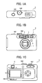
- FIGS. 1A to 1C are external views of a digital camera as an imaging apparatus according to the embodiment of the present invention.
- FICx 1A is a top view thereof
- FIG. 1B is a front view thereof
- FIG. 1C is a rear view thereof.
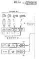
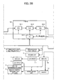
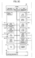
- FIG 2 is a block diagram which illustrates a system configuration inside the digital camera.
- a symbol C denotes the digital camera as the imaging apparatus.
- a sub-liquid crystal display 1 On a top surface of the digital camera C, a sub-liquid crystal display 1, a release switch SW1 and a mode dial SW2 are provided.
- a stroboscopic light emitting section 3 In a front side of the digital camera C, a stroboscopic light emitting section 3, an optical finder 4, a ranging unit 5, a remote control receiving light section 6 and a lens barrel unit 7 are provided.
- the lens barrel unit 7 is equipped with photographing lenses.
- the optical finder 4 In a rear side of the digital camera C, the optical finder 4, an LED (Light-Emitting Diode) for AF 8, an LED for stroboscopic light 9, an LCD (Liquid Crystal Display) monitor 10 and so on are provided.
- a numeral 104 denotes a digital still camera processor. (Hereinafter, simply called a processor.)
- the processor 104 has a built-in CPU (Central processing Unit). Each part of the digital camera C is controlled by the processor 104.
- the processor 104 is equipped with a CCD (Charge-Coupled Device) 1 signal processing block 104-1, a CCD 2 signal processing block 104-2, a CPU block 104-3, a local SRAM (Static Random Access Memory) block 104-4, a USB block 104-5, a serial block 104-6, a JPEG codec block 104-7, a resize block 104-8, a video signal output block 104-9 and a memory card controller block 104-10.
- CCD Charge-Coupled Device
- CCD 2 Charge-Coupled Device
- CPU block 104-3 a local SRAM (Static Random Access Memory) block 104-4
- USB block 104-5 a serial block 104-6
- JPEG codec block 104-7 Joint Photographic Codec
- resize block 104-8 a video signal output block 104-9
- a memory card controller block 104-10 Each of these blocks 104-1 to 104-10 is mutually connected via a bus line.
- an SDRAM Serial Dynamic Random Access Memory
- a RAM Random Access Memory
- a ROM Read Only Memory
- an internal memory 120 stores a control program Pro, a parameter and so on.
- the internal memory 120 memorizes image data of photographed images. And these are also connected to the processor 104 via the bus line.
- RAW-RGB image data image data on which a white balance correction and a ⁇ correction are performed.
- YUV image data image data converted into brightness data and color difference data
- JPEG image data image data compressed in a JPEG format
- control program Pro stored in the ROM 108 is loaded into a memory of the processor 104, and then is run. Each part of the digital camera C is controlled by this control program Pro.
- the lens barrel unit 7 includes a zoom optical system 7-1, a focus optical system 7-2, an aperture stop unit 7-3 and a mechanical shutter unit 7-4.
- the zoom optical system 7-1, the focus optical system 7-2, the aperture stop unit 7-3 and the mechanical shutter unit 7-4 are respectively driven by a zoom motor 7-1b, a focus motor 7-2b, an aperture stop motor 7-3b and a mechanical shutter motor 7-4b.
- each of these motors 7-1b to 7-4b is driven by a motor driver 7-5.
- the motor driver 7-5 is controlled by the CPU block 104-3 of the processor 104,
- F/E-IC Front-End Integrated Circuit
- the F/E-IC 102 is composed of a CDS (Correlated Double Sampling) 102-1, an AGC (Automatic Gain Control) 102-2, an ADC (Analog Digital Convertor) 102-3 and a TG (Timing Generator) 102-4.
- the ADC 102-3 converts an analog image signal into a digital image signal.
- the FB-IC 102 converts the analog image signal into the digital image signal, and then outputs to the CCD 1 signal processing block 104-1.
- the lens barrel unit 7, the CCD 1 O1 and the F/E-IC 102 have a function as an imaging section which continuously images a photographic subject.
- the CCD 1 signal processing block 104-1 works as an image data processing section which processes image data.
- a timing of sampling the image signal is that a VD ⁇ HD (Vertical Synchronization-Horizontal Synchronization) signal from the CCD 1 signal processing block 104-1 is fed back to the TG 102-4 and thereby is performed.
- VD ⁇ HD Very Synchronization-Horizontal Synchronization
- the CPU block 104-3 of the processor 104 is connected to a sound recording circuit 115-1, a sound reproducing circuit 116-1, a stroboscopic light circuit 114, a ranging unit 5 and a sub-CPU 109.
- the stroboscopic light circuit 114 emits light from the stroboscopic light emitting section 3.
- the ranging unit 5 measures a distance between a photographic subject.
- the sub-LCD 1 via the LCD driver 111, the remote control receiving light section 6, the LED for AF 8, the LED for stroboscopic light 9, an operation key unit and a buzzer 113 arc connected to and controlled by the sub-CPU 109.
- the operation key unit includes each switch SW1, SW14 and so on.
- the sub CPU 109 observes an input state of a signal to the remote control receiving light section 6 and an input state to the operation key unit.
- An LCD driver 117 and a video amplifier 118 are connected to the video signal output block 104-9 of the processor 104.
- the LCD driver 117 drives the LCD monitor 10.
- the video amplifier 118 amplifies a video signal and performs an impedance matching.
- the LCD monitor 10 is connected to the LCD driver 117.
- a video jack 119 which is for connecting to external monitor devices such as TV and so on is connected to the video amplifier 118.
- the video signal output block 104-9 converts image data into a video signal and outputs to the external monitor devices connected to the LCD monitor 10 or the video jack 119.
- the LCD monitor 10 is used for monitoring a photographic subject while photographing, for displaying a photographed image and for displaying a recorded image in a memory card or an internal memory 120.
- a function as a detector which detects at least one target photographic subject from images continuously imaged by the imaging section, is performed.
- plural detection modes are prepared as a detection mode which detects the photographic subject.
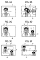
- FIGS. 3A to 3F are explanatory drawings for explaining various kinds of processing patterns being set corresponding to the detection mode which detects a target photographic subject.
- FIGS. 3A and 3B illustrate at least two different detection processing speed processing patterns, A0 and A1, which are classified corresponding to a direction of the target photographic subject in an entire image area.
- FIGS. 3C and 3D illustrate at least two different detection processing speed processing patterns, B0 and B1, which are classified corresponding to a proportion (size) of the target photographic subject in the entire image area.
- FIGS. 3E and 3F illustrate at least two different detection processing speed processing patterns, C0 and C1, which are classified corresponding to a range of a detection area where the target photographic subject is detected.
- a face image P of a person as a photographic subject (Hereinafter, simply called a face.) on an image plane is illustrated.
- FIG. 3A a state in which a photographic subject is scanned in a horizontal direction H relative to the image plane so that a detector can detect a face P of a target photographic subject is illustrated.
- FIG. 3B a state in which the subjects are scanned in the horizontal direction H and in a vertical direction V to the image plane so that the detector can detect the faces P of the target photographic subjects is illustrated.
- FIG. 3B In the processing pattern A1 illustrated in FIG. 3B , twofold scanning compared with the processing pattern A0 illustrated in FIG. 3A is performed, therefore the processing pattern A1 illustrated in FIG. 3B is a relatively slow processing pattern compared with the processing pattern A0 illustrated in FIG. 3A , when the processing pattern A0 is regarded as a fast processing pattern.
- camera users usually photograph in a horizontal format (i.e. holding a camera horizontally when photographing.), therefore FIG. 3A corresponds to a scene assuming that a frequency of photographing is relatively high.
- FIG. 3B corresponds to a scene assuming that a frequency of photographing is relatively low.
- FIG. 3C a state in which a large face P of the photographic subject in a frame L0 is scanned so that the detector can detect the face P of the target photographic subject is illustrated.
- FIG. 3D a state in which a large face P of the photographic subject in the frame L0 and a small face P of the photographic subject in the frame L1 are scanned so that the detector can detect faces P of the target photographic subjects is illustrated.
- a processing pattern B1 illustrated in FIG. 3D twofold scanning compared with a processing pattern B0 illustrated in FIG. 3C is performed, therefore the processing pattern B1 illustrated in FIG. 3D is a relatively slow processing pattern compared with the processing pattern B0 illustrated in FIG. 3C , when the processing pattern B0 is regarded as a fast processing pattern.
- FIG. 3C corresponds to a scene assuming that the frequency of photographing is relatively high.
- FIG. 3D corresponds to a scene assuming that the frequency of photographing is relatively low.
- FIG. 3E a state in which a small detection area K0 of a central part relative to the entire image area is scanned so that the detector can detect the face P of the target photographic subject is illustrated.
- FIG. 3F a larger detection area K1 than the small detection area K0 of the central part in regard to the entire image area is scanned so that the detector can detect the face P of the target photographic subj ect.
- the processing pattern C1 illustrated in FIG. 3F scans a larger area than the detection area illustrated in FIG. 3E . Therefore, the processing pattern C1 illustrated in FIG. 3F is a relatively slow processing pattern compared with the processing pattern C0 illustrated in FIG. 3E , when the processing pattern C0 is regarded as a fast processing pattern.
- FIG. 3E corresponds to a scene assumed that the frequency of photographing is relatively high.
- FIG. 3F corresponds to a scene assuming that the frequency of photographing is relatively low.
- Each processing pattern of these is memorized and stored, for example, in the ROM 108.
- the processer 104 has a role of setting a detection mode by choosing processing patterns and making a combination of three types of processing patterns. These are the three types of processing patterns. A0 and A1 are the processing patterns which perform detections corresponding to a direction of the face P. B0 and B1 are the processing patterns which perform detections corresponding to a size of the face P. C0 and C1 are the processing patterns which perform detections corresponding to a detection area. The processor 104 respectively chooses either A0 or A1, either B0 or B1 and either C0 or C1, and then those three processing patterns are combined. And the detection mode is set by the processor 104.
- the number of the detection modes by combinations of those three processing patterns is 8 in total, however, here, the number of the detection modes set by a setting means is 6.
- the detection modes m are variables having integers 0, 1, 2, 3, 4 and 5. Each detection mode m is described in a Table 1 below.
- the combination of these processing patterns corresponds to a scene assuming that a frequency of photographing is relatively the highest, and corresponds to a mode that the frequency of photographing is high in which a detection processing speed for detecting a target photographic subject is relatively the fastest.
- this combination is the most commonly used type of the processing pattern combination. Moreover, this combination is a combination of the processing patterns in which each the detection processing speed is relatively fast.
- the combination of these processing patterns (A0, B0, C1) corresponds to a middle mode assuming that the frequency of photographing is low next to a mode corresponding to a low frequency of photographing mode in which a detection processing speed for detecting a target photographic subject is relatively the slowest described later.
- the combination of these processing patterns (A1, B1, C1) corresponds to a scene assuming that the frequency of photographing is relatively low, and corresponds to a low frequency of photographing mode in which a detection processing speed for detecting a target photographic subject is relatively the slowest.
- this combination is a combination of the processing patterns in which each the detection processing speed is slow, therefore it is a mode in which the detection processing speed is the slowest.
- the processor 104 sets these detection modes described above for the CCD 1 signal processing block 104-1, and the processor 104 also has a function as a controller which controls the CCD 1 signal processing block 104-1 such that each of these detection modes described above is sequentially set for the CCD 1 signal processing block 104-1.
- the processor 104 controls the CCD 1 signal processing block 104-1 such that each detection mode is performed sequentially from a mode in which a frequency of photographing is high toward a mode in which the frequency of photographing is low through a middle mode.
- a digital camera when a face detection mode is set, performs a process flow illustrated in FIG. 4 .
- This face detection process is performed alongside a focusing process, an exposure adjustment process and a monitoring image displaying process.
- a combination of processing patterns (A0, B0, C0) is set for the CCD 1 signal processing block 104-1.
- the CCD 1 signal processing block 104-1 captures image data G1 at a predetermined timing from image data G continuously obtained as image data while monitoring (image data while photographing standby), and performs a detection process based on the combination of the processing patterns (A0, B0, C0).
- the CCD 1 signal processing block 104-1 performs the detection process in a horizontal direction in a small area K0, and performs the detection process for a face P in which a size is equivalent to a frame L0.
- This face recognition process technology is known and disclosed in such as Japanese patent publication number 2003-107335 and so on, therefore it is not explained in detail.
- the processor 104 judges whether at least one face P is detected by the CCD 1 signal processing block 104-1 in the detection area K0 or not (Step S.3). When at least one face P is detected, the face detection process is shifted to Step S.5 and the face detection is judged to be ended or not. When the face detection process is ended, the process flow is ended. When the face detection process continues, the face detection process is shifted to Step S.2. In the Step S.2, as illustrated in FIG. 5 , new data G1' are captured and the face detection process is performed, and a loop of the Steps S.2, S.3 and S.5 is repeated.
- the processor 104 sets the CCD 1 signal processing block 104-1 for a combination of processing patterns (A1, B0, C0).
- the face detection process is shifted to the Step S.5.
- the face detection process is shifted to the Step S.2 by the processor 104, and the processor 104 makes the CCD 1 signal processing block 104-1 perform the detection process having a combination of processing patterns (A1, B0, C0).
- the CCD 1 signal processing block 104-1 performs the detection process in a horizontal direction and in a vertical direction in a small area K0, and performs the detection process for a face P in which a size is equivalent to a frame L0.
- a coordinate value of a face image detected by the processes described above, for example, is successively memorized in the RAM 107, is updated, and is referred to in processes of a focusing control, an exposure adjustment and a monitoring image displaying.
- FIG. 9 is a flowchart for explaining an embodiment when performing a tracking process based on a result of a face image detection process.
- a combination of processing patterns (A0, B0, C0) is set for the CCD 1 signal processing block 104-1.
- the CCD 1 signal processing block 104-1 captures image data G1 at a predetermined timing from image data G while monitoring, which is illustrated in FIG. 10 , and performs the detection process based on the combination of the processing patterns (A0, B0, C0) (Step S.12).
- the processor 104 judges whether at least one face P is detected in a detection area K0 or not (Step S.13). When at least one face P is not detected, the face detection process is shifted to Step 5.14, the detection mode m is set to a next detection mode and the face detection is judged to be ended or not (Step S.15). Contents of controlling processes from the Steps S.11 to S.15 are the same as the contents of the processes from the Steps S.1 to S.5 explained before, therefore they are not explained in detail.
- Step S.13 when at least one face is detected, the face detection process is shifted to a tracking process mode after Step S.16 by the processor 104.
- Step S.18 the processor 104 judges whether the tracking is successful or not (Step S.18).
- the tracking counter is incremented by one by the processor 104 (Step S.19), and the processor 104 judges whether the number of times of the tracking is over a predetermined number of times N or not (Step S.20).
- the number of times of the tracking is defined as a limit value, which clears an accumulation of a tracking error. Because while the tracking is repeated many times, tracking not a target photographic subject but a different photographic subject may be occurring. In addition, the different photographic subject from the target photographic subject may be captured as image data and this different photographic subject may be also a new target photographic subject.
- the face detection process is shifted to Step S.21 and the processor 104 judges whether the face detection is ended or not. And when the face detection is not ended, the face detection process is shifted to the Step S.17 and the tracking process is repeated. When the face detection is ended, the face detection process is shifted to the Step. S 15, and the processor 104 judges again whether the face detection is ended or not and makes the face detection process end.
- Step S.20 when the tracking counter n is over the predetermined number of times N, the face detection process is shifted to the Step S.15 and the processor 104 judges whether the face detection is ended or not. And when the face detection is not ended, the face detection process is shifted to the Step S.12 and the processor 104 performs the face detection process. When making the face detection mode end, the face detection process is shifted to END and the processor 104 makes the face detection end.
- image data G1 are captured and a face image detection is performed.
- image data G1" are captured from the image data G at a predetermined timing.
- the captured image data G1" are judged as to whether there is a face image as a tracking object or not.
- new image data G1 are captured and the face image detection process is repeatedly performed.
- the face image detection process is skipped while tracking, therefore a speed-up of the face image detection can be achieved.
- An imaging apparatus is configured to classify detection modes in three types to shift detection modes stepwise and to detect a target photographic subject.
- the three types of the detection modes are a first mode which corresponds to a scene assuming that a frequency of photographing is relatively high and a detection processing speed detecting a target photographic subject is relatively the fastest, a second mode which corresponds to a scene assuming that the frequency of photographing is relatively low and the detection processing speed detecting the target photographic subject is relatively the slowest and a third mode (middle mode) is between the both modes described above.
- an imaging apparatus can be obtained without a significant rise in cost, can prevent a detection error from occurring as much as possible in a photographic subject detection process and also before photographing, and can improve an average performance rate of a detection mode corresponding to a scene assuming that the frequency of photographing is relatively high.
Landscapes
- Engineering & Computer Science (AREA)
- Theoretical Computer Science (AREA)
- Multimedia (AREA)
- Physics & Mathematics (AREA)
- General Physics & Mathematics (AREA)
- Computer Vision & Pattern Recognition (AREA)
- Health & Medical Sciences (AREA)
- General Health & Medical Sciences (AREA)
- Signal Processing (AREA)
- Evolutionary Computation (AREA)
- Artificial Intelligence (AREA)
- Databases & Information Systems (AREA)
- Computing Systems (AREA)
- Human Computer Interaction (AREA)
- Medical Informatics (AREA)
- Software Systems (AREA)
- Oral & Maxillofacial Surgery (AREA)
- Data Mining & Analysis (AREA)
- Life Sciences & Earth Sciences (AREA)
- Bioinformatics & Cheminformatics (AREA)
- Bioinformatics & Computational Biology (AREA)
- Evolutionary Biology (AREA)
- General Engineering & Computer Science (AREA)
- Studio Devices (AREA)
- Exposure Control For Cameras (AREA)
- Image Processing (AREA)
- Image Analysis (AREA)
Abstract
Description
- The present invention relates to an imaging apparatus equipped with an image recognition means as a detector which detects at least one target subject to be photographed from images continuously imaged by an imaging section, and to a photographic subject detection method.
- There is known a digital camera as an imaging apparatus that is equipped with an image recognition means as a detector which detects at least one target photographic subject from images continuously imaged by an imaging section. For example, a digital camera is disclosed in
Japanese patent publication numbers 2003-107335 2006-60329 - In addition, to improve a spced-up of a processing speed of a detector, there is also known, for example, in
Japanese patent publication number 2005-215750 - Moreover, there is also known, for example, in
Japanese patent publication number 2005-130468 - However, in the digital camera disclosed in
Japanese patent publication number 2005-215750 - In addition, in the digital camera disclosed in
Japanese patent publication number 2005-130468 Japanese patent publication number 2005-130468 - Moreover, in
Japanese patent publication numbers 2003-107335 2006-60329 - An object of the invention is to provide an imaging apparatus and a photographic subj ect detection method, which can prevent a detection error from occurring as much as possible in a photographic subject detection process and also before photographing, and which can improve an average performance rate of a detection mode corresponding to a scene assuming that a frequency of photographing is relatively high without a significant rise in cost.
- An imaging apparatus according to an embodiment of the present invention comprises: an imaging section; a detector which detects at least one target subject to be photographed from images continuously imaged by the imaging section; and a controller which sets to the detector a detection mode including a first detection mode, a second detection mode and a third detection mode, the first detection mode corresponding to a scene in which a frequency of photographing is relatively high and having relatively the fastest detection processing speed for detecting the at least one target photographic subject, the second detection mode corresponding to a scene in which the frequency of photographing is relatively low and having relatively the slowest detection processing speed for detecting the at least one target photographic subject, and the third detection mode corresponding to a scene in which the frequency of photographing is less than the first detection mode and having a detection processing speed for detecting the at least one target photographic subject slower than that of the first detection mode, and which controls the detector to perform successively each of the first detection mode to the third detection mode in order of the first detection mode, the third detection mode and the second detection mode.
- Preferably, the detection mode includes at least two processing patterns in which the detection processing speed is different and which are classified corresponding to a direction of the at least one target photographic subject.
- Preferably, the detection mode includes at least two processing patterns in which the detection processing speed is different and which are classified corresponding to a size of the at least one target photographic subject. '
- Preferably, the detection mode includes at least two processing patterns in which the detection processing speed is different and which are classified corresponding to a detection area where the at least one target photographic subject is detected.
- Preferably, the detection mode includes at least two processing patterns in which the detection processing speed is different and which are classified corresponding to the direction of the at least one target photographic subject, the at least two processing patterns in which the detection processing speed is different and which are classified corresponding to the size of the at least one target photographic subject and the at least two processing patterns in which the detection processing speed is different and which are classified corresponding to the detection area where the at least one target photographic subject is detected, and wherein the first detection mode includes processing patterns in which each of the detection processing speed is fast and which are classified corresponding to the direction of the at least one target photographic subject, corresponding to the size of the at least one target photographic subject in an image area and corresponding to the detection area where the at least one target photographic subject is detected, and wherein the second detection mode includes processing patterns in which each of the detection processing speed is slow and which are classified corresponding to the direction of the at least one target photographic subject, corresponding to the size of the at least one target photographic subject in an image area and corresponding to the detection area where the at least one target photographic subject is detected.
- Preferably, the at least two processing patterns in which the detection processing speed is different and which are classified corresponding to the direction of the at least one target photographic subject, include a fast processing pattern in which a detection process is performed in a horizontal direction relative to a photographic subject as an object, and a slow processing pattern in which the detection process is performed in horizontal and vertical directions relative to the photographic subject as the object.
- Preferably, the at least two processing patterns in which the detection processing speed is different and which are classified corresponding to the size of the at least one target photographic subject, include a fast processing pattern in which a detection process is performed on a large photographic subject in an image area as an object, and a slow processing pattern in which the detection process is performed on large and small photographic subjects in the image area as the objects.
- Preferably, the at least two processing patterns in which the detection processing speed is different and which are classified corresponding to the detection area where the at least one target photographic subject is detected, include a fast processing pattern in which a detection process is performed on a small detection area of a central part in regard to an entire image area as an object, and a slow processing pattern in which the detection process is performed on a larger detection area than the small detection area as the object.
- Preferably, the controller repeatedly performs the detection mode when the at least one target photographic subject is detected by performing the detection mode.
- Preferably, the at least one target photographic subject includes a face of a person.
- A photographic subject detection method according to an embodiment of the present invention comprises: performing a first detection process of detecting at least one target subject to be photographed by setting a first detection mode which corresponds to a scene in which a frequency of photographing is relatively high and which has relatively the fastest detection process speed for detecting the at least the one target photographic subject; performing a second detection process of detecting the at least one target photographic subject by setting a second detection mode having a detection processing speed for detecting the at least one target photographic subject slower than that of the first detection mode, when the at least one target photographic subject is not detected by the first detection mode; and performing a third detection process of detecting the at least one target photographic subject by setting a third detection mode corresponding to a scene in which the frequency of photographing is relatively low and which has relatively the slowest detection processing speed for detecting the at least one target photographic subject, when the at least one target photographic subject is not detected by the second detection mode.
- Preferably, the photographic subject detection method further comprises: repeating the same detection process of the first detection process to the third detection process when the at least one target photographic subject is detected by that one of the first detection process to the third detection process.
- Preferably, the target photographic subject includes a face of a person.
- Preferably, the at least one of the first to the third detection modes includes at least two processing patterns in which the detection processing speed is different and which are classified corresponding to a direction of the at least one target photographic subject.
- Preferably, the at least one of the first to the third detection modes includes at least two processing patterns in which the detection processing speed is different and which are classified corresponding to a size of the at least one target photographic subject.
- Preferably, the at least one of the first to the third detection modes includes at least two processing patterns in which the detection processing speed is different and which are classified corresponding to a detection area where the at least one target photographic subject is detected.
- Preferably, the at least two processing patterns in which the detection processing speed is different and which are classified corresponding to the direction of the at least one target photographic subject, include a fast processing pattern in which a detection process is performed in a horizontal direction relative to a photographic subject as an object, and a slow processing pattern in which the detection process is performed in horizontal and vertical directions relative to the photographic subject as the object.
- Preferably, the at least two processing patterns in which the detection processing speed is different and which are classified corresponding to the size of the at least one target photographic subject, include a fast processing pattern in which a detection process is performed on a large photographic subject in an image area as an object, and a slow processing pattern in which the detection process is performed on large and small photographic subjects in the image area as the objects.
- Preferably, the at least two processing patterns in which the detection processing speed is different and which are classified corresponding to the detection area where the at least one target photographic subject is detected, include a fast processing pattern in which a detection process is performed on a small detection area of a central part in regard to an entire image area as an object, and a slow processing pattern in which the detection process is performed on a larger detection area than the small detection area as the object.
- The invention will now be described by way of non-limiting example, with reference to the accompanying drawings, in which:
-
FIG 1A is a top view illustrating an external appearance of a digital camera as an imaging apparatus according to an embodiment of the present invention. -
FIG. 1B is a front view illustrating the external appearance of the digital camera as the imaging apparatus according to the embodiment of the present invention. -
FIG. 1C is a rear view illustrating the external appearance of the digital camera as the imaging apparatus according to the embodiment of the present invention. -
FIG. 2 is a block diagram which illustrates a system configuration inside the digital camera illustrated inFIGS. 1A to 1C . -
FIG. 3A explains a processing pattern being set corresponding to a detection mode which detects a target photographic subject, and illustrates one of at least two different detection processing speed processing patterns which are classified corresponding to a direction of the target photographic subject in an entire image area. -
FIG 3B explains a processing pattern being set corresponding to the detection mode which detects the target photographic subject, and illustrates another one of at least two different detection processing speed processing patterns which are classified corresponding to the direction of the target photographic subject in the entire image area. -
FIG. 3C explains a processing pattern being set corresponding to the detection mode which detects the target photographic subject, and illustrates one of at least two different detection processing speed processing patterns which are classified corresponding to a proportion (size) of the target photographic subject in the entire image area. -
FIG. 3D explains a processing pattern being set corresponding to the detection mode which detects the target photographic subject, and illustrates another one of at least two different detection processing speed processing patterns which are classified corresponding to the proportion (size) of the target photographic subject in the entire image area. -
FIG. 3E explains a processing pattern being set corresponding to the detection mode which detects the target photographic subject, and illustrates one of at least two different detection processing speed processing patterns which are classified corresponding to a range of detection area in which the target photographic subject is detected. -
FIG. 3F explains a processing pattern being set corresponding to the detection mode which detects the target photographic subject, and illustrates another one of at least two different detection processing speed processing patterns which are classified corresponding to the range of detection area in which the target photographic subject is detected. -
FIG. 4 is a flowchart which explains a setting of the detection mode according to the embodiment of the present invention. -
FIG 5 explains an image data capture in the detection process illustrated inFIG. 4 . -
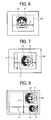
FIG. 6 explains a detection process, which is a combination of processing patterns ofFIGS. 3A, 3C and 3E among processing patterns illustrated inFIGS. 3A to 3F . -
FIG. 7 explains a detection process, which is a combination of processing patterns ofFIGS. 3B, 3C and 3E among processing patterns illustrated inFIGS. 3A to 3F . -
FIG. 8 explains a detection process, which is a combination of processing patterns ofFIGS. 3B, 3D and 3F among processing patterns illustrated inFIGS. 3A to 3F . -
FIG. 9 is a flowchart which explains an embodiment when a tracking process is performed based on a result of a face image detection process. -
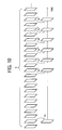
FIG. 10 explains an image data capture in the tracking process illustrated inFIG. 9 . - Hereinafter, with reference to drawings, an embodiment according to the present invention will be explained.
-
FIGS. 1A to 1C , are external views of a digital camera as an imaging apparatus according to the embodiment of the present invention. FICx 1A is a top view thereof,FIG. 1B is a front view thereof andFIG. 1C is a rear view thereof.FIG 2 is a block diagram which illustrates a system configuration inside the digital camera. - In
FIGS. 1A to 1C , a symbol C denotes the digital camera as the imaging apparatus. On a top surface of the digital camera C, asub-liquid crystal display 1, a release switch SW1 and a mode dial SW2 are provided. - In a front side of the digital camera C, a stroboscopic
light emitting section 3, anoptical finder 4, a rangingunit 5, a remote control receivinglight section 6 and alens barrel unit 7 are provided. Thelens barrel unit 7 is equipped with photographing lenses. In a rear side of the digital camera C, theoptical finder 4, an LED (Light-Emitting Diode) forAF 8, an LED forstroboscopic light 9, an LCD (Liquid Crystal Display) monitor 10 and so on are provided. - In
FIG. 2 , a numeral 104 denotes a digital still camera processor. (Hereinafter, simply called a processor.) Theprocessor 104 has a built-in CPU (Central processing Unit). Each part of the digital camera C is controlled by theprocessor 104. - The
processor 104 is equipped with a CCD (Charge-Coupled Device) 1 signal processing block 104-1, a CCD 2 signal processing block 104-2, a CPU block 104-3, a local SRAM (Static Random Access Memory) block 104-4, a USB block 104-5, a serial block 104-6, a JPEG codec block 104-7, a resize block 104-8, a video signal output block 104-9 and a memory card controller block 104-10. Each of these blocks 104-1 to 104-10 is mutually connected via a bus line. - In the outside of the
processor 104, an SDRAM (Synchronous Dynamic Random Access Memory) 103, a RAM (Random Access Memory) 107, a ROM (Read Only Memory) 108 and aninternal memory 120 are provided. TheROM 108 stores a control program Pro, a parameter and so on. Theinternal memory 120 memorizes image data of photographed images. And these are also connected to theprocessor 104 via the bus line. - In the
SDRAM 103, RAW-RGB image data (image data on which a white balance correction and a γ correction are performed.), YUV image data (image data converted into brightness data and color difference data) and JPEG image data (image data compressed in a JPEG format) are saved. - When a power switch SW14 is on, the control program Pro stored in the
ROM 108 is loaded into a memory of theprocessor 104, and then is run. Each part of the digital camera C is controlled by this control program Pro. - All the processes described later are performed by mainly the
processor 104 by performing this control program Pro. - The
lens barrel unit 7 includes a zoom optical system 7-1, a focus optical system 7-2, an aperture stop unit 7-3 and a mechanical shutter unit 7-4. - The zoom optical system 7-1, the focus optical system 7-2, the aperture stop unit 7-3 and the mechanical shutter unit 7-4 are respectively driven by a zoom motor 7-1b, a focus motor 7-2b, an aperture stop motor 7-3b and a mechanical shutter motor 7-4b.
- In addition, each of these motors 7-1b to 7-4b is driven by a motor driver 7-5. The motor driver 7-5 is controlled by the CPU block 104-3 of the
processor 104, - A photographic subject image formed in a receiving light section of the
CCD 101 by each of the zoom optical system 7-1 and the focus optical system 7-2, is converted into an image signal by theCCD 101, and this image signal is outputted to an F/E-IC (Front-End Integrated Circuit) 102. - The F/
E-IC 102 is composed of a CDS (Correlated Double Sampling) 102-1, an AGC (Automatic Gain Control) 102-2, an ADC (Analog Digital Convertor) 102-3 and a TG (Timing Generator) 102-4. The ADC 102-3 converts an analog image signal into a digital image signal. - After the F/
E-IC 102 has performed predetermined processes such as a noise reduction process, a gain adjustment process and so on, the FB-IC 102 converts the analog image signal into the digital image signal, and then outputs to theCCD 1 signal processing block 104-1. - The
lens barrel unit 7, theCCD 1 O1 and the F/E-IC 102 have a function as an imaging section which continuously images a photographic subject. TheCCD 1 signal processing block 104-1 works as an image data processing section which processes image data. - In addition, a timing of sampling the image signal is that a VD·HD (Vertical Synchronization-Horizontal Synchronization) signal from the
CCD 1 signal processing block 104-1 is fed back to the TG 102-4 and thereby is performed. - The CPU block 104-3 of the
processor 104 is connected to a sound recording circuit 115-1, a sound reproducing circuit 116-1, a stroboscopiclight circuit 114, a rangingunit 5 and a sub-CPU 109. The stroboscopiclight circuit 114 emits light from the stroboscopiclight emitting section 3. The rangingunit 5 measures a distance between a photographic subject. These circuits described above are controlled by the CPU block 104-3. - The sub-LCD 1 via the
LCD driver 111, the remote control receivinglight section 6, the LED forAF 8, the LED forstroboscopic light 9, an operation key unit and abuzzer 113 arc connected to and controlled by thesub-CPU 109. The operation key unit includes each switch SW1, SW14 and so on. In addition, thesub CPU 109 observes an input state of a signal to the remote control receivinglight section 6 and an input state to the operation key unit. - An
LCD driver 117 and avideo amplifier 118 are connected to the video signal output block 104-9 of theprocessor 104. TheLCD driver 117 drives theLCD monitor 10. Thevideo amplifier 118 amplifies a video signal and performs an impedance matching. The LCD monitor 10 is connected to theLCD driver 117. Avideo jack 119 which is for connecting to external monitor devices such as TV and so on is connected to thevideo amplifier 118. - The video signal output block 104-9 converts image data into a video signal and outputs to the external monitor devices connected to the
LCD monitor 10 or thevideo jack 119. - The LCD monitor 10 is used for monitoring a photographic subject while photographing, for displaying a photographed image and for displaying a recorded image in a memory card or an
internal memory 120. - In this digital camera, when the power switch SW14 is on, a key of the operation key unit is operated and a detecting menu which detects a face of a target photographic subject from a menu displayed on the
LCD monitor 10 is chosen, and the CPU block 104-3 enters a mode which performs a detection process. - When the
CCD 1 signal processing block 104-1 enters a mode which performs a detection process, a function as a detector, which detects at least one target photographic subject from images continuously imaged by the imaging section, is performed. Here, plural detection modes are prepared as a detection mode which detects the photographic subject. -
FIGS. 3A to 3F are explanatory drawings for explaining various kinds of processing patterns being set corresponding to the detection mode which detects a target photographic subject.FIGS. 3A and 3B illustrate at least two different detection processing speed processing patterns, A0 and A1, which are classified corresponding to a direction of the target photographic subject in an entire image area.FIGS. 3C and 3D illustrate at least two different detection processing speed processing patterns, B0 and B1, which are classified corresponding to a proportion (size) of the target photographic subject in the entire image area.FIGS. 3E and 3F illustrate at least two different detection processing speed processing patterns, C0 and C1, which are classified corresponding to a range of a detection area where the target photographic subject is detected. In each of these drawings, a face image P of a person as a photographic subject (Hereinafter, simply called a face.) on an image plane is illustrated. - In
FIG. 3A , a state in which a photographic subject is scanned in a horizontal direction H relative to the image plane so that a detector can detect a face P of a target photographic subject is illustrated. InFIG. 3B , a state in which the subjects are scanned in the horizontal direction H and in a vertical direction V to the image plane so that the detector can detect the faces P of the target photographic subjects is illustrated. - In the processing pattern A1 illustrated in
FIG. 3B , twofold scanning compared with the processing pattern A0 illustrated inFIG. 3A is performed, therefore the processing pattern A1 illustrated inFIG. 3B is a relatively slow processing pattern compared with the processing pattern A0 illustrated inFIG. 3A , when the processing pattern A0 is regarded as a fast processing pattern. In addition, camera users usually photograph in a horizontal format (i.e. holding a camera horizontally when photographing.), thereforeFIG. 3A corresponds to a scene assuming that a frequency of photographing is relatively high. On the other hand,FIG. 3B corresponds to a scene assuming that a frequency of photographing is relatively low. - In
FIG. 3C , a state in which a large face P of the photographic subject in a frame L0 is scanned so that the detector can detect the face P of the target photographic subject is illustrated. InFIG. 3D , a state in which a large face P of the photographic subject in the frame L0 and a small face P of the photographic subject in the frame L1 are scanned so that the detector can detect faces P of the target photographic subjects is illustrated. In a processing pattern B1 illustrated inFIG. 3D , twofold scanning compared with a processing pattern B0 illustrated inFIG. 3C is performed, therefore the processing pattern B1 illustrated inFIG. 3D is a relatively slow processing pattern compared with the processing pattern B0 illustrated inFIG. 3C , when the processing pattern B0 is regarded as a fast processing pattern. - In addition, when photographing a person as a photographic subject, there are many opportunities for a proportion of a face P of a target photographic subject in an entire image area to be large. Therefore,
FIG. 3C corresponds to a scene assuming that the frequency of photographing is relatively high. On the other hand,FIG. 3D corresponds to a scene assuming that the frequency of photographing is relatively low. - In
FIG. 3E , a state in which a small detection area K0 of a central part relative to the entire image area is scanned so that the detector can detect the face P of the target photographic subject is illustrated. InFIG. 3F , a larger detection area K1 than the small detection area K0 of the central part in regard to the entire image area is scanned so that the detector can detect the face P of the target photographic subj ect. - The processing pattern C1 illustrated in
FIG. 3F scans a larger area than the detection area illustrated inFIG. 3E . Therefore, the processing pattern C1 illustrated inFIG. 3F is a relatively slow processing pattern compared with the processing pattern C0 illustrated inFIG. 3E , when the processing pattern C0 is regarded as a fast processing pattern. - In addition, when photographing a person as a photographic subject, there usually are many opportunities for a face P of a target photographic subject to be in a center of an image plane and there usually are few opportunities for the face P of the target photographic subject to be in a peripheral part of the image plane. Therefore,
FIG. 3E corresponds to a scene assumed that the frequency of photographing is relatively high. On the other hand,FIG. 3F corresponds to a scene assuming that the frequency of photographing is relatively low. - Each processing pattern of these is memorized and stored, for example, in the
ROM 108. - The
processer 104 has a role of setting a detection mode by choosing processing patterns and making a combination of three types of processing patterns. These are the three types of processing patterns. A0 and A1 are the processing patterns which perform detections corresponding to a direction of the face P. B0 and B1 are the processing patterns which perform detections corresponding to a size of the face P. C0 and C1 are the processing patterns which perform detections corresponding to a detection area. Theprocessor 104 respectively chooses either A0 or A1, either B0 or B1 and either C0 or C1, and then those three processing patterns are combined. And the detection mode is set by theprocessor 104. - The number of the detection modes by combinations of those three processing patterns is 8 in total, however, here, the number of the detection modes set by a setting means is 6. The detection modes m are
variables having integers -
[Table 1] DETECTION MODE (m) 0 1 2 3 4 5 DIRECTION(S) OF FACE(S) VERTICAL VERTICAL AND HORIZONTAL VERTICAL VERTICAL AND HORIZONTAL VERTICAL VERTICAL AND HORIZONTAL SIZE(S) OF FACE(S) LARGE LARGE LARGE AND SMALL LARGE LARGE LARGE AND SMALL SIZE OF DETECTION AREA SMALL SMALL SMALL LARGE LARGE LARGE - This is because there are many opportunities for a face of a photographic subject to be in close-up and to be in a center of an image plane as a composition of a photograph when usual photographing is performed in a horizontal format. Therefore, this combination is the most commonly used type of the processing pattern combination. Moreover, this combination is a combination of the processing patterns in which each the detection processing speed is relatively fast.
- The detection mode m=1 is a mode to detect an image of the face, in which the directions of the faces are vertical and horizontal, the sizes of the faces are large and the detection area is small as an object. The combination of these processing patterns (A1, B0, C0), corresponds to a scene assuming that the frequency of photographing is relatively high next to the detection mode m=0, and corresponds to a middle mode in which a detection processing speed for detecting a target photographic subject is relatively fast.
- This is because it is assumed that there are fairly many opportunities for camera users to photograph in a vertical format by holding a camera vertically.
- The detection mode m=2 is a mode to detect an image of the face, in which the direction of the face is vertical, the sizes of the faces are large and small and the detection area is small as an object. The combination of these processing patterns (A0, B1, C0) corresponds to a scene assuming that the frequency of photographing is relatively high next to the detection mode m=1, and corresponds to a middle mode in which a detection processing speed for detecting a target photographic subject is relatively fast.
- This is because there also are fairly many opportunities for a proportion of each face P to be small in an entire image plane, for example, when photographing many people such as a group photograph and so on.
- The detection mode m=3 is a mode to detect an image of the face, in which the directions of the faces are vertical and horizontal, the size of the face is large and the detection area is large as an object. The combination of these processing patterns (A1, B0, C1) corresponds to a scene assuming that the frequency of photographing is relatively high next to the detection mode m=2, and corresponds to a middle mode in which a detection processing speed for detecting a target photographic subject is relatively fast.
- This is because it is considered that there are not so many opportunities for camera users to photograph a face P of a photographic subject at an edge of an image plane when photographing in a horizontal format. However, it is also assumed that there are some opportunities for camera users to photograph the face P of the photographic subject at the edge of the image plane when photographing in a vertical format.
- The detection mode m=4 is a mode to detect an image of the face, in which the direction of the face is vertical, the size of the face is large and the detection area is large as an object. The combination of these processing patterns (A0, B0, C1) corresponds to a middle mode assuming that the frequency of photographing is low next to a mode corresponding to a low frequency of photographing mode in which a detection processing speed for detecting a target photographic subject is relatively the slowest described later.
- This is because it is considered that there are not so many opportunities for camera users to photograph a face P of a target photographic subject which is large at an edge of an image plane when photographing in a horizontal format.
- The detection mode m=5 is a mode to detect an image of the face, in which the directions of the faces are vertical and horizontal, the sizes of the faces are large and small and the detection area is large as an object. The combination of these processing patterns (A1, B1, C1) corresponds to a scene assuming that the frequency of photographing is relatively low, and corresponds to a low frequency of photographing mode in which a detection processing speed for detecting a target photographic subject is relatively the slowest.
- This is because it is considered that there are almost few opportunities for camera users to photograph a face P of a target subject which is small at an edge of an image plane when photographing in a vertical format. In addition, this combination is a combination of the processing patterns in which each the detection processing speed is slow, therefore it is a mode in which the detection processing speed is the slowest.
- The
processor 104 sets these detection modes described above for theCCD 1 signal processing block 104-1, and theprocessor 104 also has a function as a controller which controls theCCD 1 signal processing block 104-1 such that each of these detection modes described above is sequentially set for theCCD 1 signal processing block 104-1. - Here, the
processor 104 controls theCCD 1 signal processing block 104-1 such that each detection mode is performed sequentially from a mode in which a frequency of photographing is high toward a mode in which the frequency of photographing is low through a middle mode. - A digital camera, when a face detection mode is set, performs a process flow illustrated in
FIG. 4 . This face detection process is performed alongside a focusing process, an exposure adjustment process and a monitoring image displaying process. - When starting the face detection process, the
processor 1 04 sets a detection mode m=0 (Step S.1). When the detection mode m=0 is set, a combination of processing patterns (A0, B0, C0) is set for theCCD 1 signal processing block 104-1. TheCCD 1 signal processing block 104-1, as illustrated inFIG. 5 , captures image data G1 at a predetermined timing from image data G continuously obtained as image data while monitoring (image data while photographing standby), and performs a detection process based on the combination of the processing patterns (A0, B0, C0). - The
CCD 1 signal processing block 104-1, as illustrated in XFIG. 6, performs the detection process in a horizontal direction in a small area K0, and performs the detection process for a face P in which a size is equivalent to a frame L0. This face recognition process technology is known and disclosed in such as Japanese patent publication number2003-107335 - The
processor 104 judges whether at least one face P is detected by theCCD 1 signal processing block 104-1 in the detection area K0 or not (Step S.3). When at least one face P is detected, the face detection process is shifted to Step S.5 and the face detection is judged to be ended or not. When the face detection process is ended, the process flow is ended. When the face detection process continues, the face detection process is shifted to Step S.2. In the Step S.2, as illustrated inFIG. 5 , new data G1' are captured and the face detection process is performed, and a loop of the Steps S.2, S.3 and S.5 is repeated. - For example, when a direction of a face P is vertical and the face P remains being in a small area K0 of a central part, the detection mode m=0 including a combination of process patterns (A0, B0, C0) is performed repeatedly.
- In the Step S.3, when at least one face is not detected by the
CCD 1 signal processing block 104-1, theprocessor 104 sets the detection mode for the detection mode m=1 (Step S.4). When the detection mode m=1 is set, theprocessor 104 sets theCCD 1 signal processing block 104-1 for a combination of processing patterns (A1, B0, C0). After theprocessor 104 sets the detection mode m=1, the face detection process is shifted to the Step S.5. In the Step S.5, when the face detection process continues, the face detection process is shifted to the Step S.2 by theprocessor 104, and theprocessor 104 makes theCCD 1 signal processing block 104-1 perform the detection process having a combination of processing patterns (A1, B0, C0). - The
CCD 1 signal processing block 104-1, as illustrated inFIG 7 , performs the detection process in a horizontal direction and in a vertical direction in a small area K0, and performs the detection process for a face P in which a size is equivalent to a frame L0. - For example, when a direction of a face P is horizontal and the face P is in a small area K0 of a central part, the face P is detected by this detection mode m=1.
- The
processor 104 performs the detection modes m from m=0 to m=4. When a face P is not detected by each of these modes, a detection process, a detection mode m=5 including a combination of processing patterns (A1, B1, C1) is performed. - In this detection mode m=5, as illustrated in
FIG. 8 , scanning is performed in a vertical direction and in a horizontal direction in a large area K1, and the detection processes for faces P in which sizes are a frame L0 and a frame L1 are performed. - For example, when a direction of a face P is horizontal and the face P is small at an edge of an image plane, the face P is detected by this detection mode m=5.
- When a face P is not detected also by this detection process of the detection mode m=5, the
processor 104, in the Step S.4, sets the detection mode m to 6 and newly sets a remainder divided by 6 for the detection mode m. That is, in the Step S.4, the detection mode m=0 is set, again, the detection processes of the detection modes m=0 to m=5 are repeated, and this process repeatedly continues until the end of the face detection process. - A coordinate value of a face image detected by the processes described above, for example, is successively memorized in the
RAM 107, is updated, and is referred to in processes of a focusing control, an exposure adjustment and a monitoring image displaying. -
FIG. 9 is a flowchart for explaining an embodiment when performing a tracking process based on a result of a face image detection process. - When starting the face detection, the
processor 104 sets the detection mode m=0 for theCCD 1 signal processing block 104-1 (Step S.11). When the detection mode m=0 is set, a combination of processing patterns (A0, B0, C0) is set for theCCD 1 signal processing block 104-1. TheCCD 1 signal processing block 104-1 captures image data G1 at a predetermined timing from image data G while monitoring, which is illustrated inFIG. 10 , and performs the detection process based on the combination of the processing patterns (A0, B0, C0) (Step S.12). - The
processor 104 judges whether at least one face P is detected in a detection area K0 or not (Step S.13). When at least one face P is not detected, the face detection process is shifted to Step 5.14, the detection mode m is set to a next detection mode and the face detection is judged to be ended or not (Step S.15). Contents of controlling processes from the Steps S.11 to S.15 are the same as the contents of the processes from the Steps S.1 to S.5 explained before, therefore they are not explained in detail. - In the Step S.13, when at least one face is detected, the face detection process is shifted to a tracking process mode after Step S.16 by the
processor 104. - In the Step S.16, the
processor 104 sets a tracking counter n to n=0 and performs a tracking process (Step S.17). Next, theprocessor 104 judges whether the tracking is successful or not (Step S.18). When the tracking is successful, the tracking counter is incremented by one by the processor 104 (Step S.19), and theprocessor 104 judges whether the number of times of the tracking is over a predetermined number of times N or not (Step S.20). - Here, the number of times of the tracking is defined as a limit value, which clears an accumulation of a tracking error. Because while the tracking is repeated many times, tracking not a target photographic subject but a different photographic subject may be occurring. In addition, the different photographic subject from the target photographic subject may be captured as image data and this different photographic subject may be also a new target photographic subject.
- When a counter value of the tracking counter n is less than or equal to the predetermined number of times N, the face detection process is shifted to Step S.21 and the
processor 104 judges whether the face detection is ended or not. And when the face detection is not ended, the face detection process is shifted to the Step S.17 and the tracking process is repeated. When the face detection is ended, the face detection process is shifted to the Step. S 15, and theprocessor 104 judges again whether the face detection is ended or not and makes the face detection process end. - In the Step S.20, when the tracking counter n is over the predetermined number of times N, the face detection process is shifted to the Step S.15 and the
processor 104 judges whether the face detection is ended or not. And when the face detection is not ended, the face detection process is shifted to the Step S.12 and theprocessor 104 performs the face detection process. When making the face detection mode end, the face detection process is shifted to END and theprocessor 104 makes the face detection end. - In the Step S.18, when the tracking is ended unsuccessfully, the face detection process is shifted to Step S.22, and the
processor 104 sets the detection mode to m=0 and then the face detection process is shifted to the Step S.15. In the Step S.15, when the face detection is not ended, the face detection process is shifted to the Step S.12 and again the detection process is sequentially performed from the detection mode m=0 toward m=5. - That is, in this tracking process mode, as illustrated in
FIG. 10 , image data G1 are captured and a face image detection is performed. When the face image is detected, image data G1" are captured from the image data G at a predetermined timing. The captured image data G1" are judged as to whether there is a face image as a tracking object or not. When the number of times of the tracking n is over the predetermined number of times N, new image data G1 are captured and the face image detection process is repeatedly performed. - According to this tracking process performing mode, the face image detection process is skipped while tracking, therefore a speed-up of the face image detection can be achieved.
- An imaging apparatus according to the embodiment of the present invention is configured to classify detection modes in three types to shift detection modes stepwise and to detect a target photographic subject. The three types of the detection modes are a first mode which corresponds to a scene assuming that a frequency of photographing is relatively high and a detection processing speed detecting a target photographic subject is relatively the fastest, a second mode which corresponds to a scene assuming that the frequency of photographing is relatively low and the detection processing speed detecting the target photographic subject is relatively the slowest and a third mode (middle mode) is between the both modes described above. Therefore, an imaging apparatus according to an embodiment of the present invention can be obtained without a significant rise in cost, can prevent a detection error from occurring as much as possible in a photographic subject detection process and also before photographing, and can improve an average performance rate of a detection mode corresponding to a scene assuming that the frequency of photographing is relatively high.
- Although the present invention has been described in terms of exemplary embodiments, it is not limited thereto. It should be appreciated that variations may be made un the embodiments described by persons skilled in the art without departing from the scope of the present invention as defined by the following claims.
Claims (19)
- An imaging apparatus, comprising:an imaging section (7, 101 and 102);a detector (104-1) which detects at least one target subject to be photographed from images continuously imaged by the imaging section (7, 101 and 102); anda controller (104) which sets to the detector a detection mode including a first detection mode, a second detection mode and a third detection mode,the first detection mode corresponding to a scene in which a frequency of photographing is relatively high and having relatively the fastest detection processing speed for detecting the at least one target photographic subject,the second detection mode corresponding to a scene in which the frequency of photographing is relatively low and having relatively the slowest detection processing speed for detecting the at least one target photographic subject, andthe third detection mode corresponding to a scene in which the frequency of photographing is less than the first detection mode and having a detection processing speed for detecting the at least one target photographic subject slower than that of the first detection mode,and which controls the detector (104-1) to perform successively each of the first detection mode to the third detection mode in order of the first detection mode, the third detection mode and the second detection mode.
- An imaging apparatus according to Claim 1, wherein the detection mode includes at least two processing patterns in which the detection processing speed is different and which are classified corresponding to a direction of the at least one target photographic subject.
- An imaging apparatus according to Claim 1 or 2, wherein the detection mode includes at least two processing patterns in which the detection processing speed is different and which are classified corresponding to a size of the at least one target photographic subject.
- An imaging apparatus according to Claim 1, 2 or 3, wherein the detection mode includes at least two processing patterns in which the detection processing speed is different and which are classified corresponding to a detection area where the at least one target photographic subject is detected.
- An imaging apparatus according to any one of Claims 1 to 4, wherein the detection mode includes at least two processing patterns in which the detection processing speed is different and which are classified corresponding to the direction of the at least one target photographic subject, the at least two processing patterns in which the detection processing speed is different and which are classified corresponding to the size of the at least one target photographic subject and the at least two processing patterns in which the detection processing speed is different and which are classified corresponding to the detection area where the at least one target photographic subject is detected,
and wherein the first detection mode includes processing patterns in which each of the detection processing speed is fast and which are classified corresponding to the direction of the at least one target photographic subj ect, corresponding to the size of the at least one target photographic subject in an image area and corresponding to the detection area where the at least one target photographic subject is detected,
and wherein the second detection mode includes processing patterns in which each of the detection processing speed is slow and which are classified corresponding to the direction of the at least one target photographic subject, corresponding to the size of the at least one target photographic subject in an image area and corresponding to the detection area where the at least one target photographic subject is detected. - An imaging apparatus according to Claim 5, wherein the at least two processing patterns in which the detection processing speed is different and which are classified corresponding to the direction of the at least one target photographic subject, include a fast processing pattern in which a detection process is performed in a horizontal direction relative to a photographic subject as an object, and a slow processing pattern in which the detection process is performed in horizontal and vertical directions relative to the photographic subject as the object.
- An imaging apparatus according to Claim 5 or 6, wherein the at least two processing patterns in which the detection processing speed is different and which are classified corresponding to the size of the at least one target photographic subject, include a fast processing pattern in which a detection process is performed on a large photographic subject in an image area as an object, and a slow processing pattern in which the detection process is performed on large and small photographic subjects in the image area as the objects.
- An imaging apparatus according to Claim 5, 6 or 7, wherein the at least two processing patterns in which the detection processing speed is different and which are classified corresponding to the detection area where the at least one target photographic subject is detected, include a fast processing pattern in which a detection process is performed on a small detection area of a central part in regard to an entire image area as an object, and a slow processing pattern in which the detection process is performed on a larger detection area than the small detection area as the object.
- An imaging apparatus according to any one of Claim 1 to Claim 5, wherein the controller (104) repeatedly performs the detection mode when the at least one target photographic subject is detected by performing the detection mode.
- An imaging apparatus according to any one of Claim 1 to Claim 9, wherein the at least one target photographic subject includes a face of a person.
- A photographic subject detection method, comprising:performing a first detection process of detecting at least one target subject to be photographed by setting a first detection mode which corresponds to a scene in which a frequency of photographing is relatively high and which has relatively the fastest detection process speed for detecting the at least the one target photographic subject;performing a second detection process of detecting the at least one target photographic subject by setting a second detection mode having a detection processing speed for detecting the at least one target photographic subject slower than that of the first detection mode, when the at least one target photographic subject is not detected by the first detection mode; andperforming a third detection process of detecting the at least one target photographic subject by setting a third detection mode corresponding to a scene in which the frequency of photographing is relatively low and which has relatively the slowest detection processing speed for detecting the at least one target photographic subject, when the at least one target photographic subject is not detected by the second detection mode.
- A photographic subject detection method according to Claim 11, further comprising:repeating the same detection process of the first detection process to the third detection process when the at least one target photographic subject is detected by that one of the first detection process to the third detection process.
- A photographic subject detection method according to Claim 11 or 12, wherein the target photographic subject includes a face of a person.
- A photographic subject detection method according to Claim 11, 12 or 13, wherein the at least one of the first to the third detection modes includes at least two processing patterns in which the detection processing speed is different and which are classified corresponding to a direction of the at least one target photographic subject.
- A photographic subject detection method according to any one of Claims 11 to 14, wherein the at least one of the first to the third detection modes includes at least two processing patterns in which the detection processing speed is different and which are classified corresponding to a size of the at least one target photographic subject.
- A photographic subject detection method according to any one of Claims 11 to 15, wherein the at least one of the first to the third detection modes includes at least two processing patterns in which the detection processing speed is different and which are classified corresponding to a detection area where the at least one target photographic subject is detected.
- A photographic subject detection method according to Claim 14,15 or 16 wherein the at least two processing patterns in which the detection processing speed is different and which are classified corresponding to the direction of the at least one target photographic subject, include a fast processing pattern in which a detection process is performed in a horizontal direction relative to a photographic subject as an object, and a slow processing pattern in which the detection process is performed in horizontal and vertical directions relative to the photographic subject as the objects.
- A photographic subject detection method according to Claim 15 or 16, wherein the at least two processing patterns in which the detection processing speed is different and which are classified corresponding to the size of the at least one target photographic subject, include a fast processing pattern in which a detection process is performed on a large photographic subject in an image area as an object, and a slow processing pattern in which the detection process is performed on large and small photographic subjects in the image area as the objects.
- A photographic subject detection method according to Claim 18, wherein the at least two processing patterns in which the detection processing speed is different and which are classified corresponding to the detection area where the at Icast one target photographic subject is detected, include a fast processing pattern in which a detection process is performed on a small detection area of a central part in regard to an entire image area as an object, and a slow processing pattern in which the detection process is performed on a larger detection area than the small detection area as the object.
Applications Claiming Priority (1)
| Application Number | Priority Date | Filing Date | Title |
|---|---|---|---|
| JP2007025396A JP4989243B2 (en) | 2007-02-05 | 2007-02-05 | Imaging device and subject detection method thereof |
Publications (3)
| Publication Number | Publication Date |
|---|---|
| EP1953679A2 true EP1953679A2 (en) | 2008-08-06 |
| EP1953679A3 EP1953679A3 (en) | 2009-08-12 |
| EP1953679B1 EP1953679B1 (en) | 2012-04-04 |
Family
ID=39535716
Family Applications (1)
| Application Number | Title | Priority Date | Filing Date |
|---|---|---|---|
| EP08250391A Ceased EP1953679B1 (en) | 2007-02-05 | 2008-02-01 | Imaging apparatus and photographic subject detection method thereof |
Country Status (2)
| Country | Link |
|---|---|
| EP (1) | EP1953679B1 (en) |
| JP (1) | JP4989243B2 (en) |
Cited By (2)
| Publication number | Priority date | Publication date | Assignee | Title |
|---|---|---|---|---|
| EP2189927A1 (en) * | 2008-11-24 | 2010-05-26 | Samsung Electronics Co., Ltd. | Method and apparatus for taking images using portable terminal |
| US7978253B2 (en) | 2007-07-18 | 2011-07-12 | Ricoh Company, Ltd. | Image pickup device using blur processing and control method thereof |
Families Citing this family (1)
| Publication number | Priority date | Publication date | Assignee | Title |
|---|---|---|---|---|
| JP2009054130A (en) | 2007-07-27 | 2009-03-12 | Ricoh Co Ltd | Image processing apparatus, image processing method, and digital still camera |
Citations (4)
| Publication number | Priority date | Publication date | Assignee | Title |
|---|---|---|---|---|
| JP2003107335A (en) | 2001-09-28 | 2003-04-09 | Ricoh Co Ltd | Imaging device, automatic focusing method, and program for causing computer to execute the method |
| JP2005130468A (en) | 2003-09-29 | 2005-05-19 | Canon Inc | Imaging apparatus and control method thereof |
| JP2005215750A (en) | 2004-01-27 | 2005-08-11 | Canon Inc | Face detection device and face detection method |
| JP2006060329A (en) | 2004-08-17 | 2006-03-02 | Fuji Photo Film Co Ltd | Device, method, and program for imaging |
Family Cites Families (5)
| Publication number | Priority date | Publication date | Assignee | Title |
|---|---|---|---|---|
| US7508961B2 (en) * | 2003-03-12 | 2009-03-24 | Eastman Kodak Company | Method and system for face detection in digital images |
| KR100580626B1 (en) * | 2003-10-31 | 2006-05-16 | 삼성전자주식회사 | Face detection method and device and security monitoring system using the same |
| JP2005322220A (en) * | 2004-04-06 | 2005-11-17 | Fuji Photo Film Co Ltd | Particular region detecting method, particular region detecting apparatus, and program therefor |
| JP4143656B2 (en) * | 2005-08-02 | 2008-09-03 | キヤノン株式会社 | Image processing apparatus, image processing method, computer program, and storage medium |
| JP4360369B2 (en) * | 2005-11-25 | 2009-11-11 | 株式会社ニコン | Electronic camera |
-
2007
- 2007-02-05 JP JP2007025396A patent/JP4989243B2/en not_active Expired - Fee Related
-
2008
- 2008-02-01 EP EP08250391A patent/EP1953679B1/en not_active Ceased
Patent Citations (4)
| Publication number | Priority date | Publication date | Assignee | Title |
|---|---|---|---|---|
| JP2003107335A (en) | 2001-09-28 | 2003-04-09 | Ricoh Co Ltd | Imaging device, automatic focusing method, and program for causing computer to execute the method |
| JP2005130468A (en) | 2003-09-29 | 2005-05-19 | Canon Inc | Imaging apparatus and control method thereof |
| JP2005215750A (en) | 2004-01-27 | 2005-08-11 | Canon Inc | Face detection device and face detection method |
| JP2006060329A (en) | 2004-08-17 | 2006-03-02 | Fuji Photo Film Co Ltd | Device, method, and program for imaging |
Cited By (2)
| Publication number | Priority date | Publication date | Assignee | Title |
|---|---|---|---|---|
| US7978253B2 (en) | 2007-07-18 | 2011-07-12 | Ricoh Company, Ltd. | Image pickup device using blur processing and control method thereof |
| EP2189927A1 (en) * | 2008-11-24 | 2010-05-26 | Samsung Electronics Co., Ltd. | Method and apparatus for taking images using portable terminal |
Also Published As
| Publication number | Publication date |
|---|---|
| JP4989243B2 (en) | 2012-08-01 |
| JP2008193387A (en) | 2008-08-21 |
| EP1953679B1 (en) | 2012-04-04 |
| EP1953679A3 (en) | 2009-08-12 |
Similar Documents
| Publication | Publication Date | Title |
|---|---|---|
| US8477993B2 (en) | Image taking apparatus and image taking method | |
| EP2026567B1 (en) | Imaging device and imaging method | |
| JP4674471B2 (en) | Digital camera | |
| CN101931752B (en) | Imaging apparatus and focusing method | |
| US8624988B2 (en) | Image pickup apparatus, image pickup method, and program thereof | |
| US8885090B2 (en) | Imaging apparatus and autofocus control method thereof | |
| KR20110062991A (en) | Digital photographing apparatus for notifying subject recognition, control method of digital photographing apparatus | |
| JP2008288975A (en) | Imaging apparatus, imaging method, and imaging program | |
| TW201301866A (en) | Image processing device, image processing method, and recording medium capable of generating wide-angle image | |
| EP1953679B1 (en) | Imaging apparatus and photographic subject detection method thereof | |
| US8514305B2 (en) | Imaging apparatus | |
| JP5429588B2 (en) | Imaging apparatus and imaging method | |
| JP2014106324A (en) | Autofocus device and imaging device | |
| JP2009017427A (en) | Imaging device | |
| JP4344622B2 (en) | Digital camera | |
| JP2001255451A (en) | Autofocus device, digital camera, and portable information input device | |
| JP2009124309A (en) | Imaging device | |
| JP2009182880A (en) | Imaging apparatus and program thereof | |
| US7864860B2 (en) | Image pickup apparatus and motion vector deciding method | |
| CN106464783B (en) | Image pickup control device, image pickup device, and image pickup control method | |
| JP5641411B2 (en) | Imaging apparatus, electronic device, image processing system, and computer-readable recording medium | |
| JP2010062825A (en) | Imaging device and method of controlling imaging | |
| JP2008090059A (en) | Imaging apparatus and autofocus control method thereof | |
| JP5641415B2 (en) | Imaging apparatus and electronic apparatus | |
| EP2091233A2 (en) | Imaging apparatus |
Legal Events
| Date | Code | Title | Description |
|---|---|---|---|
| PUAI | Public reference made under article 153(3) epc to a published international application that has entered the european phase |
Free format text: ORIGINAL CODE: 0009012 |
|
| AK | Designated contracting states |
Kind code of ref document: A2 Designated state(s): AT BE BG CH CY CZ DE DK EE ES FI FR GB GR HR HU IE IS IT LI LT LU LV MC MT NL NO PL PT RO SE SI SK TR |
|
| AX | Request for extension of the european patent |
Extension state: AL BA MK RS |
|
| PUAL | Search report despatched |
Free format text: ORIGINAL CODE: 0009013 |
|
| AK | Designated contracting states |
Kind code of ref document: A3 Designated state(s): AT BE BG CH CY CZ DE DK EE ES FI FR GB GR HR HU IE IS IT LI LT LU LV MC MT NL NO PL PT RO SE SI SK TR |
|
| AX | Request for extension of the european patent |
Extension state: AL BA MK RS |
|
| 17P | Request for examination filed |
Effective date: 20091209 |
|
| AKX | Designation fees paid |
Designated state(s): DE FR GB |
|
| 17Q | First examination report despatched |
Effective date: 20101228 |
|
| GRAP | Despatch of communication of intention to grant a patent |
Free format text: ORIGINAL CODE: EPIDOSNIGR1 |
|
| RIC1 | Information provided on ipc code assigned before grant |
Ipc: H04N 5/232 20060101ALI20110923BHEP Ipc: G06K 9/00 20060101AFI20110923BHEP Ipc: G06K 9/32 20060101ALI20110923BHEP Ipc: G06K 9/62 20060101ALI20110923BHEP |
|
| GRAS | Grant fee paid |
Free format text: ORIGINAL CODE: EPIDOSNIGR3 |
|
| GRAA | (expected) grant |
Free format text: ORIGINAL CODE: 0009210 |
|
| AK | Designated contracting states |
Kind code of ref document: B1 Designated state(s): DE FR GB |
|
| REG | Reference to a national code |
Ref country code: GB Ref legal event code: FG4D |
|
| REG | Reference to a national code |
Ref country code: DE Ref legal event code: R096 Ref document number: 602008014587 Country of ref document: DE Effective date: 20120531 |
|
| PLBE | No opposition filed within time limit |
Free format text: ORIGINAL CODE: 0009261 |
|
| STAA | Information on the status of an ep patent application or granted ep patent |
Free format text: STATUS: NO OPPOSITION FILED WITHIN TIME LIMIT |
|
| 26N | No opposition filed |
Effective date: 20130107 |
|
| REG | Reference to a national code |
Ref country code: DE Ref legal event code: R097 Ref document number: 602008014587 Country of ref document: DE Effective date: 20130107 |
|
| REG | Reference to a national code |
Ref country code: FR Ref legal event code: PLFP Year of fee payment: 9 |
|
| REG | Reference to a national code |
Ref country code: FR Ref legal event code: PLFP Year of fee payment: 10 |
|
| REG | Reference to a national code |
Ref country code: FR Ref legal event code: PLFP Year of fee payment: 11 |
|
| PGFP | Annual fee paid to national office [announced via postgrant information from national office to epo] |
Ref country code: DE Payment date: 20180219 Year of fee payment: 11 Ref country code: GB Payment date: 20180216 Year of fee payment: 11 |
|
| PGFP | Annual fee paid to national office [announced via postgrant information from national office to epo] |
Ref country code: FR Payment date: 20180223 Year of fee payment: 11 |
|
| REG | Reference to a national code |
Ref country code: DE Ref legal event code: R119 Ref document number: 602008014587 Country of ref document: DE |
|
| GBPC | Gb: european patent ceased through non-payment of renewal fee |
Effective date: 20190201 |
|
| PG25 | Lapsed in a contracting state [announced via postgrant information from national office to epo] |
Ref country code: GB Free format text: LAPSE BECAUSE OF NON-PAYMENT OF DUE FEES Effective date: 20190201 Ref country code: DE Free format text: LAPSE BECAUSE OF NON-PAYMENT OF DUE FEES Effective date: 20190903 |
|
| PG25 | Lapsed in a contracting state [announced via postgrant information from national office to epo] |
Ref country code: FR Free format text: LAPSE BECAUSE OF NON-PAYMENT OF DUE FEES Effective date: 20190228 |