EP1953591A2 - Camera system and lens apparatus - Google Patents
Camera system and lens apparatus Download PDFInfo
- Publication number
- EP1953591A2 EP1953591A2 EP08100022A EP08100022A EP1953591A2 EP 1953591 A2 EP1953591 A2 EP 1953591A2 EP 08100022 A EP08100022 A EP 08100022A EP 08100022 A EP08100022 A EP 08100022A EP 1953591 A2 EP1953591 A2 EP 1953591A2
- Authority
- EP
- European Patent Office
- Prior art keywords
- diaphragm
- value
- flicker
- coils
- camera system
- Prior art date
- Legal status (The legal status is an assumption and is not a legal conclusion. Google has not performed a legal analysis and makes no representation as to the accuracy of the status listed.)
- Withdrawn
Links
- 238000001514 detection method Methods 0.000 claims description 30
- 230000008859 change Effects 0.000 claims description 11
- 238000012937 correction Methods 0.000 claims description 8
- 230000006870 function Effects 0.000 description 24
- 230000005284 excitation Effects 0.000 description 22
- 230000007246 mechanism Effects 0.000 description 16
- 238000000034 method Methods 0.000 description 15
- 230000008569 process Effects 0.000 description 13
- 238000012545 processing Methods 0.000 description 12
- 230000006835 compression Effects 0.000 description 10
- 238000007906 compression Methods 0.000 description 10
- 230000003287 optical effect Effects 0.000 description 10
- 238000004891 communication Methods 0.000 description 7
- 239000004973 liquid crystal related substance Substances 0.000 description 7
- 238000006243 chemical reaction Methods 0.000 description 6
- 238000010586 diagram Methods 0.000 description 6
- 238000003384 imaging method Methods 0.000 description 6
- 230000011514 reflex Effects 0.000 description 6
- 230000009467 reduction Effects 0.000 description 2
- 238000002310 reflectometry Methods 0.000 description 2
- 230000002411 adverse Effects 0.000 description 1
- 230000005540 biological transmission Effects 0.000 description 1
- 230000000903 blocking effect Effects 0.000 description 1
- 238000001444 catalytic combustion detection Methods 0.000 description 1
- 230000006866 deterioration Effects 0.000 description 1
- 238000011156 evaluation Methods 0.000 description 1
- 238000003702 image correction Methods 0.000 description 1
- 230000010354 integration Effects 0.000 description 1
- 238000012423 maintenance Methods 0.000 description 1
- 229910044991 metal oxide Inorganic materials 0.000 description 1
- 150000004706 metal oxides Chemical class 0.000 description 1
- 238000012986 modification Methods 0.000 description 1
- 230000004048 modification Effects 0.000 description 1
- 230000004044 response Effects 0.000 description 1
- 239000004065 semiconductor Substances 0.000 description 1
- 230000035945 sensitivity Effects 0.000 description 1
Images





Classifications
-
- G—PHYSICS
- G03—PHOTOGRAPHY; CINEMATOGRAPHY; ANALOGOUS TECHNIQUES USING WAVES OTHER THAN OPTICAL WAVES; ELECTROGRAPHY; HOLOGRAPHY
- G03B—APPARATUS OR ARRANGEMENTS FOR TAKING PHOTOGRAPHS OR FOR PROJECTING OR VIEWING THEM; APPARATUS OR ARRANGEMENTS EMPLOYING ANALOGOUS TECHNIQUES USING WAVES OTHER THAN OPTICAL WAVES; ACCESSORIES THEREFOR
- G03B9/00—Exposure-making shutters; Diaphragms
- G03B9/02—Diaphragms
- G03B9/06—Two or more co-operating pivoted blades, e.g. iris type
-
- G—PHYSICS
- G03—PHOTOGRAPHY; CINEMATOGRAPHY; ANALOGOUS TECHNIQUES USING WAVES OTHER THAN OPTICAL WAVES; ELECTROGRAPHY; HOLOGRAPHY
- G03B—APPARATUS OR ARRANGEMENTS FOR TAKING PHOTOGRAPHS OR FOR PROJECTING OR VIEWING THEM; APPARATUS OR ARRANGEMENTS EMPLOYING ANALOGOUS TECHNIQUES USING WAVES OTHER THAN OPTICAL WAVES; ACCESSORIES THEREFOR
- G03B7/00—Control of exposure by setting shutters, diaphragms or filters, separately or conjointly
- G03B7/08—Control effected solely on the basis of the response, to the intensity of the light received by the camera, of a built-in light-sensitive device
- G03B7/081—Analogue circuits
- G03B7/085—Analogue circuits for control of aperture
-
- H—ELECTRICITY
- H04—ELECTRIC COMMUNICATION TECHNIQUE
- H04N—PICTORIAL COMMUNICATION, e.g. TELEVISION
- H04N23/00—Cameras or camera modules comprising electronic image sensors; Control thereof
- H04N23/60—Control of cameras or camera modules
- H04N23/63—Control of cameras or camera modules by using electronic viewfinders
-
- H—ELECTRICITY
- H04—ELECTRIC COMMUNICATION TECHNIQUE
- H04N—PICTORIAL COMMUNICATION, e.g. TELEVISION
- H04N23/00—Cameras or camera modules comprising electronic image sensors; Control thereof
- H04N23/60—Control of cameras or camera modules
- H04N23/66—Remote control of cameras or camera parts, e.g. by remote control devices
- H04N23/663—Remote control of cameras or camera parts, e.g. by remote control devices for controlling interchangeable camera parts based on electronic image sensor signals
-
- H—ELECTRICITY
- H04—ELECTRIC COMMUNICATION TECHNIQUE
- H04N—PICTORIAL COMMUNICATION, e.g. TELEVISION
- H04N23/00—Cameras or camera modules comprising electronic image sensors; Control thereof
- H04N23/60—Control of cameras or camera modules
- H04N23/667—Camera operation mode switching, e.g. between still and video, sport and normal or high- and low-resolution modes
-
- H—ELECTRICITY
- H04—ELECTRIC COMMUNICATION TECHNIQUE
- H04N—PICTORIAL COMMUNICATION, e.g. TELEVISION
- H04N23/00—Cameras or camera modules comprising electronic image sensors; Control thereof
- H04N23/70—Circuitry for compensating brightness variation in the scene
- H04N23/745—Detection of flicker frequency or suppression of flicker wherein the flicker is caused by illumination, e.g. due to fluorescent tube illumination or pulsed LED illumination
-
- H—ELECTRICITY
- H04—ELECTRIC COMMUNICATION TECHNIQUE
- H04N—PICTORIAL COMMUNICATION, e.g. TELEVISION
- H04N23/00—Cameras or camera modules comprising electronic image sensors; Control thereof
- H04N23/70—Circuitry for compensating brightness variation in the scene
- H04N23/75—Circuitry for compensating brightness variation in the scene by influencing optical camera components
Definitions
- the present invention relates to power saving measures for diaphragm driving control of a camera system and a lens apparatus.
- the presently used digital single lens reflex camera includes a live view function (moving image checking function) which enables a user to check captured images by sequentially displaying image signals read from an image sensor on a display unit such as a liquid crystal display (LCD) mounted on the back of the camera.
- a live view function moving image checking function
- LCD liquid crystal display
- an exposure value during shooting of a still image is determined by metering light of the captured scenes. Further, an exposure value of an image displayed as a live view image on the display unit such as an LCD is controlled by an automatic exposure control function.
- the number of diaphragm driving times is reduced as much as possible to prevent a deterioration in focus detection accuracy and to secure quietness, and the diaphragm is controlled with full aperture priority.
- the image sensor has to be used as both an imaging sensor and a light metering sensor to realize the live view function in the digital single lens reflex camera.
- the aperture needs to be reduced in order to prevent saturation.
- the aperture needs to be reduced in order to detect flicker occurring due to an illuminance change of the captured scene.
- the reduced state of the aperture cannot be maintained, which causes a change in the aperture reducing position.
- the aperture becomes different from the set aperture, which causes an error in the light metering value and accuracy of exposure control is reduced.
- This phenomenon is not only applicable to a digital single lens reflex camera equipped with the live view function. Also in a camera system equipped with a diaphragm control device which drives a diaphragm by a stepping motor, the above described phenomenon occurs if the camera is configured to enter a power cut-off state after a diaphragm button is pressed to reduce the aperture.
- Japanese Patent Application Laid-Open No. 2002-156681 discusses a camera system which drives the diaphragm using a stepping motor.
- the camera system discussed there opens the diaphragm again to execute light metering anew if a shooting instruction is received while a diaphragm button is pressed, and carries out shooting while the current is being applied.
- the present invention in its first aspect provides a camera system for driving a diaphragm by a stepping motor including first and second coils and capable of 2-phase driving as specified in claims 1 to 4.
- the present invention in its second aspect provides a camera system for driving a diaphragm by a stepping motor including first and second coils and capable of 2-phase driving as specified in claims 5 to 8.
- the present invention in its third aspect provides a lens apparatus as specified in claim 9.
- Fig. 1 is a block diagram illustrating a configuration of an imaging apparatus according to a first exemplary embodiment of the present invention.
- Fig. 2 is a flowchart illustrating an operation flow according to the first exemplary embodiment of the present invention.
- Fig. 3 is a diagram illustrating a configuration of a stepping motor according to the first exemplary embodiment of the present invention.
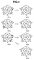
- Fig. 4 is a schematic diagram illustrating an operation of the stepping motor according to the first exemplary embodiment of the present invention.
- Fig. 5 is a block diagram illustrating a configuration of an imaging apparatus according to a second exemplary embodiment of the present invention.
- Fig. 6 is a flowchart illustrating an operation flow according to the second exemplary embodiment of the present invention.
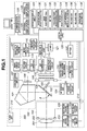
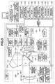
- Fig. 7 is a table illustrating a control phase of diaphragm driving in each shooting mode.
- Fig. 1 is a block diagram illustrating an electrical configuration incorporated in a single lens reflex type digital camera system according to a first exemplary embodiment of the present invention.
- the camera system of the exemplary embodiment includes a camera body 100, a lens unit 200 detachably attached by a mount mechanism (not illustrated), and a first electrical contact point group 210 disposed in the mount unit (not illustrated).
- a single photographic lens 201 is illustrated for convenience.
- camera systems usually include a plurality of lenses.
- the camera system also includes a diaphragm 202 which has a light amount adjust mechanism.
- the first electrical contact point group 210 transfers a control signal, a state signal, and a data signal between the camera body 100 and the lens unit 200. Further, the first electrical contact point group 210 includes a function of supplying currents of various voltages, and a function of transmitting a signal to a system controller 120 upon connection with the lens unit 200.
- communication is carried out between the camera body 100 and the lens unit 200 to enable driving of the photographic lens 201 and the diaphragm 202 in the lens unit 200.
- the system controller 120 includes a central processing unit (CPU) for controlling the camera body 100.
- the system controller 120 also functions as a correction unit.
- the first electrical contact point group 210 can be configured to transmit not only electrical communication but also optical communication or voice communication.
- the first electrical contact point group 210 and the system controller 120 constitute a lens detection unit.
- a shooting beam of light from a subject is guided through the photographic lens 201 and the diaphragm 202 to a quick return mirror 102 that can be driven in an arrow direction (illustrated).
- a center of the quick return mirror 102 is a half mirror through which a part of light beam passes when the quick return mirror 102 is lowered.
- the passed light beam is reflected downward at a submirror 103 mounted on the quick return mirror 102.
- An AF sensor unit 104 operating in a well-known phase difference detection method includes a field lens, a reflection mirror, a secondary image forming lens, a stop, and a line sensor constituted of a plurality of CCDs which are arranged near an image forming plane (not illustrated).
- a focus detection circuit 105 controls the AF sensor unit 104 to detect focus using the phase difference detection method.
- the focus detection unit includes the AF sensor unit 104 and the focus detection circuit 105.
- a pentaprism 101 reverses a subject image formed on a focusing screen (not illustrated) left, right, up and down to convert the image into an erect image.
- An eyepiece lens 106 guides the light beam (finder image) emitted from the pentaprism 101 to the eyes of a photographer (not illustrated).
- the shooting light beam reflected on the quick return mirror 102 reaches the eyes of the photographer through the pentaprism 101 and the eyepiece 106.
- An image sensor 112 for example, a charge coupled device (CCD) sensor or a complementally metal oxide semiconductor (CMOS) sensor, has a photoelectric conversion function.
- a focal plane shutter 108 includes leading and trailing shutter blades, and controls transmission/blocking of the light beam from the photographic lens 201.
- the leading and trailing shutter blades of the focal plane shutter 108 are driven by a driving source including a spring. The spring has to be charged to resume an operation after the shutter travels.
- a filter 109 has a function of guiding only visible light to the image sensor 112 while cutting off infrared light, as well as a function as an optical low-pass filter.
- the quick return mirror 102 When the quick return mirror 102 is raised, the light beam from the photographic lens 201 reaches the image sensor 112 through the focal plane shutter 108 and the filter 109.
- a lens driving mechanism 203 moves the photographic lens 201 in an optical axis direction to focus the camera.
- a lens control circuit 204 controls the lens driving mechanism 203.
- a diaphragm driving mechanism 205 drives the diaphragm 202.
- a diaphragm control circuit 206 controls the diaphragm driving mechanism.
- the lens control circuit 204 and the diaphragm control circuit 206 are connected to the system controller 120.
- a shutter charge mirror driving mechanism 110 controls up-and-down driving of the quick return mirror 102 and charging of the focal plane shutter 108.
- a shutter control circuit 111 controls travel of the leading and trailing shutter blades of the focal plane shutter 108.
- a light metering circuit 107 is an automatic exposure device connected to a light metering sensor (not illustrated) arranged near the eyepiece lens 106.
- An EEPROM 122 is a storage unit for storing parameters necessary for controlling the camera body 100, camera ID information for enabling individual identification of the camera body 100, AF correction data adjusted by a reference lens, or an automatic exposure correction value.
- the shutter charge mirror driving mechanism 110, the shutter control circuit 111, the light metering circuit 107, and the EEPROM 122 are connected to the system controller 120.
- the light metering sensor (not illustrated) connected to the light metering circuit 107 measures luminance of a subject. Its output is supplied through the light metering circuit 107 to the system controller 120.
- the lens control circuit 204 includes a lens storage device for storing information unique to a lens, such as a focal length, a full aperture value, or lens ID allocated to each lens, and information received from the system controller 120.
- the system controller 120 controls the lens driving mechanism 203 to form a subject image on the image sensor 112.
- the system controller 120 controls the diaphragm driving mechanism 205 for driving the diaphragm 202 based on a set Av value (diaphragm value), and outputs a control signal to the shutter control circuit 111 based on a set Tv value (shutter speed).
- An image data controller 115 (hereinafter, referred to as digital signal processor (DSP)) performs control of the image sensor 112, and correction or processing of image data input from the image sensor 112 based on commands from the system controller 120.
- DSP digital signal processor
- the correction or the processing of the image data includes white balance processing.
- the white balance processing is a function of correcting a largest luminance part of a shot image to a predetermined color (white color).
- the white balance processing can change a correction amount according to a command from the system controller 120.
- the system controller 120 and the DSP 115 constitute a light metering unit.
- the light metering unit divides an image signal into areas by the DSP 115, supplies an integrated value for each Bayer pixel in each area, to the system controller 120, and evaluates an integration signal by causing the system controller 120 to perform light metering.
- a timing pulse generation circuit 114 outputs a timing signal necessary for driving the image sensor 112.
- An analog-to-digital (A/D) converter 113 receives a timing pulse generated by the timing pulse generation circuit 114 together with the image sensor 112, and converts an analog signal corresponding to the subject image output from the image sensor 112, into a digital signal.
- a DRAM 121 temporarily stores image data before it is subjected to processing or data conversion into a predetermined format.
- a digital-to-analog (D/A) converter 116 converts digital data obtained from the DSP 115 into analog data.
- An image compression circuit 119 compresses or converts the image data stored in the DRAM 121 (e.g., compression by JPEG compression system).
- the converted image data is stored in a recording medium 401 (i.e., a recording unit) such as for example a hard disk, a flash memory or a floppy disk.
- a contrast detection circuit 140 passes the image data corrected by the DSP 115 through a filter of predetermined frequency characteristics based on a command from the system controller 120. Then, the contrast detection circuit 140 evaluates contrast in a predetermined direction of the image signal obtained by executing predetermined gamma processing, and supplies its result to the system controller 120.
- the timing pulse generation circuit 114, the A/D converter 113, the D/A converter 121, the image compression circuit 119, and the contrast detection circuit 140 are connected to the DSP 115.
- the recording medium 401 is connected to the image compression circuit 119.
- the DSP 115, the image compression circuit 119, and the recording medium 401 constitute a recording unit.
- An encoder circuit 117 converts an output of the D/A converter 116 into a video signal (e.g., NTSC signal) necessary for driving an image display device 118.
- the image display device 118 displays image data captured by the image sensor 112, and it is generally an image display device such as an LCD which includes a color liquid crystal display device.
- the image display device 118 is connected to the D/A converter 116 via the encoder circuit 117.
- the DSP 115 converts the image data of the DRAM 121 into an analog signal by the D/A converter 116 to output the signal to the encoder circuit 117.
- the D/A converter 116, the image display device 118, and the encoder circuit 117 constitute an image display unit.
- the system controller 120 communicates with the lens control circuit 204 to adjust the focal position so that the contrast evaluation value can be higher than a predetermined level.
- the DSP 115, the contrast detection circuit 140, the system controller 120, the lens control circuit 204, the lens driving mechanism 203, and the photographic lens 201 constitute a second automatic focus detection unit.
- An operation display unit (123, 124, 125) displays information about an operation mode or exposure information (shutter time of second or diaphragm value) of the digital camera according to the exemplary embodiment in an external liquid crystal display device 124 or an internal liquid crystal display device 125.
- a shooting mode selection button 130 sets a mode to cause the digital camera to execute an operation desired by the user.
- a main electronic dial 131, and a setting switch (SW) 132 are provided.
- a focusing point selection button 133 (corresponding to focusing point selection unit) selects a focus detection position to be used from among a plurality of focus detection positions of the AF sensor unit 104.
- an AF selection button 134, and a light metering mode selection button 135 are provided.
- a release switch (SW1) 136 starts a shooting preparation such as light metering or focusing.
- a release switch (SW2) 137 starts an imaging operation.
- a finder mode selection switch 138 is also provided.
- the operation display circuit 123, the shooting mode selection button 130, the main electronic dial 131, the setting SW 132, the focusing point selection button 133, the AF mode selection button 134, and the light metering mode selection button 135 are connected to the system controller 120.
- the release switch (SW1) 136, the release switch (SW2) 137, and the finder mode selection switch SW1 138 are connected to the system controller 120.
- the external and internal liquid crystal display devices 124 and 125 constitute the operation display unit while the external liquid crystal display device 124 corresponds to an external display unit, and the internal liquid crystal display unit 125 corresponds to an internal display unit.
- the operation display circuit 123 and the system controller 120 constitute a display control unit.
- the finder mode selection switch 138 is configured to switch between an optical finder mode and a live view display mode.
- the optical finder mode enables checking of a light beam passed through the eyepiece lens 106.
- image signals received by the image sensor 112 are sequentially displayed by the image display device 118.
- a flash unit 300 is detachably attached to the camera body 100 by a mount mechanism (not illustrated), and is configured to emit a flash light.
- a second electrical contact point group 310 is disposed in the mount unit.
- the second electrical contact point group 310 has a function of transferring a control signal, a state signal, or a data signal between the camera body 100 and the flash unit 300, and a function of transmitting a signal to the system controller 120 when the flash unit 300 is connected.
- the camera body 100 communicates with the flash unit 300 to enable controlling of flash light emission.
- the contact point group 310 can be configured to transmit not only electrical communication but also optical communication or voice communication.
- FIG. 2 illustrates an operation flow according to the first exemplary embodiment of the present invention.
- step S001 by powering ON when the battery is changed, the system controller 120 initializes a flag or a control variable, and records a control parameter or a set value in the EEPROM 122 which is a nonvolatile memory.
- step S002 the system controller 120 checks the state of the finder mode selection switch 138.
- step S003 if the optical finder mode is selected, and to step S011 if the live view display mode is selected.
- step S003 the system controller 120 checks the state of the release switch (SW1) 136, and returns to step S002 if the state is OFF. If the state is ON, the process proceeds to step S004.
- step S004 the system controller 120 communicates with the lens control circuit 204 in response to outputs from the AF sensor unit 104 and the focus detection unit 105, and drives the photographic lens 201 to move to a desired position with the lens driving mechanism 203 in order to adjust the focus state.
- step S005 the system controller 120 carries out light metering calculation to obtain an exposure control value (i.e. Bv value) according to the state of the light metering mode selection button 135 and an output from the light metering circuit 107, and holds the exposure control value.
- an exposure control value i.e. Bv value
- step S006 the system controller 120 checks the state of the release switch (SW 2) 137. If the release switch (SW2) 137 is in the OFF state, the process proceeds to step S007. If the release switch (SW2) 137 is in the ON state, the process proceeds to step S008, and the system controller 120 starts a shooting operation.
- step S007 the system controller 120 checks the state of the release switch (SW1) 136, and returns to step S006 if the ON state is maintained. If the release switch (SW1) 136 is in an OFF state, the system controller 120 discards the exposure control value it holds, and the process returns to step S002.
- step S008 the system controller 120 determines a Tv value, an Av value, and an Sv value for the shooting operation, according to the exposure control value (Bv value) calculated in step S005 and the state of the shooting mode.
- the shooting mode is a shooting parameter which can be set by the shooting mode selection button 130.
- an Av priority mode, a Tv priority mode, an automatic setting mode, and a manual setting mode can be selected.
- the shooting mode is not limited to such modes.
- the system controller 120 notifies the determined Av value to the diaphragm control circuit 206. Based on the notified Av value, the diaphragm control circuit 206 sends a pulse corresponding to a diaphragm driving amount to the diaphragm driving mechanism 205 so as to drive a diaphragm to the desired diaphragm position.
- the diaphragm driving mechanism 205 operates the stepping motor based on the received pulse signal, reduces the aperture to the desired position, and keeps a coil in an energized state to maintain the aperture position.
- the stepping motor of the exemplary embodiment illustrated in Fig. 3 is a 1-2 phase excitation type which includes yokes 251 and 252, a rotor 253, and coils 254 and 255.
- the rotational angle (step angle) of the rotor 253 can be finely controlled. Accordingly, an aperture reducing position of the diaphragm can be controlled with a fine phase.
- magnetic poles of the rotor are divided into six: three S poles and three N poles.
- the stepping motor of the 1-2 phase excitation is stabilized in a state of 1-phase excitation (401a and 402a), and a state of 2-phase excitation (403a).
- the stable state continues (401b and 402b) causing no change in the aperture reducing position.
- the rotor rotates to a stable position (403b and 403c) causing a change in the diaphragm state.
- the energization has to be continued even after the diaphragm is driven to the desired position.
- step S009 the system controller 120 causes the leading and trailing shutter blades to travel, through the shutter control circuit 111 using the Tv value set in step S008 to read an image signal from the image sensor 112.
- the read image signal is subjected to image correction processing by the DSP 115.
- image correction processing by the DSP 115.
- image conversion is carried out by the image compression circuit 119 in the JPEG compression format, an image is recorded in the recording medium 401.
- step S010 the system controller 120 checks a state of the release switch (SW1) 136, and returns to step S006 if the ON state is maintained. If the release switch (SW1) 136 is in the OFF state, the system controller 120 discards the exposure control value it holds, and drives the diaphragm to the fully open aperture position. Then, the process returns to step S002 after cutting-off the coil energization.
- step S011 the mirror is raised, and the mechanical shutter is opened. A light beam passing through the lens unit 200 is incident on the image sensor 112 to start exposure.
- the system controller 120 converts image signals sequentially read from the image sensor 112 into digital signals using the A/D converter 113, and subjects the images to image processing at the DSP 115.
- the images are subjected to D/A conversion at the D/A converter 116, and encoded by the encoder circuit 117. Then, the images are transferred to a VRAM (not illustrated), and sequentially displayed by the image display device 118 mounted on the backside of the camera, or the like.
- the system controller 120 calculates a light metering value based on signals sequentially read from the image sensor 112. During the live view function operation, the light metering operation is periodically repeated.
- the system controller 120 obtains an exposure control value (Bv value) based on the calculated light metering value, and calculates an Av value, a Tv value, and an Sv value so that an output signal from the image sensor 112 can be equal to a predetermined luminance level.
- Bv value exposure control value
- the Av value is preferentially set so that diaphragm driving can be operated in a manner matching a phase of 1-phase excitation of the stepping motor, and the diaphragm is driven to a position corresponding to the Av value.
- the Av value, the Tv value, and the Sv value used for this shooting are calculated to satisfy a Bv value, based on a program diagram different from that used for automatic exposure control of live view displaying.
- Diaphragm control during a live view operation will be described referring to Fig. 4 .
- the diaphragm is preferentially controlled to a full aperture to prevent a reduction in accuracy of focus detection. Therefore, exposure control is carried out by adjusting storage time or the gain value.
- the diaphragm is driven to reduce the amount of light received by the image sensor 112.
- an exposure control value (diaphragm position based on a diaphragm value during live view) calculated based on a result of light metering calculation has to match actual exposure conditions (diaphragm position during the shooting).
- the diaphragm position has to be maintained and not be allowed to change.
- the diaphragm changes its position if the energization is cut off from the state of 2-phase excitation. Accordingly, the energization has to be continued to maintain the diaphragm position.
- the diaphragm position moves from the actual diaphragm position based on a diaphragm value which is set during the live view. However, since the set value is not changed, it is determined that the diaphragm position has not moved.
- the diaphragm is in a position (e.g., shifted to the full aperture side by 1/3 stages) different from a position set according to the diaphragm value.
- the diaphragm position moves by an amount equal to 1 + 1/3 stages as a result, so that a diaphragm value intended by the photographer is not realized.
- the aperture is reduced by matching diaphragm driving during the live view operation, with a phase of 1-phase excitation of the stepping motor whose aperture reduced state is not changed even when coil energization is cut off.
- Fig. 7 illustrates the control phase of diaphragm driving (optical finder mode or live view display mode) of the stepping motor for 1-2 phase excitation in the shooting mode.
- driving of the stepping motor is controlled not to hold a diaphragm position in 2-phase excitation in the live view display mode.
- control resolution of the diaphragm becomes rough (i.e. the resolution is reduced) in the live view display mode.
- the diaphragm is controlled in a state other than the full aperture during the live view operation.
- application of the invention is not limited to this exemplary embodiment.
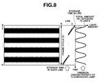
- Fig. 8 is a view illustrating a relation between an emission cycle of a fluorescent lamp and a signal of an image sensor in each line. As illustrated in Fig.
- a stripe pattern i.e., line flicker
- the stripe pattern appears according to a large and small amount of light from the fluorescent lamp.
- An interval of the stripe corresponds to a flicker cycle. Therefore, the flicker cycle can be obtained by calculating the interval of the stripe. More specifically, the cycle can be calculated by detecting a horizontal projection image.
- an actual object has various degrees of reflection within an image plane. Accordingly, the horizontal projection of an image signal in Fig. 8 is influenced by the reflectivity of the object.
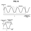
- a horizontal axis denotes a number of vertical lines. If the number of vertical lines is multiplied by scanning time of one horizontal line, time is obtained. If the amplitude of the waveform illustrated in Fig. 10 (A) exceeds a predetermined value, a flicker phenomenon is confirmed.
- the following process is performed. Two windows are provided in the waveform as illustrated in Fig. 10(A) , and self-correlation of the waveforms within both windows is computed. As a result, a waveform of the correlation result is obtained as illustrated in Fig. (B) .
- a waveform cycle of the correlation result in Fig. 10 (B) is a flicker cycle and, when there is no flicker, amplitude of the waveform in Fig. 10 (B) becomes small. Accordingly, a correlation value threshold is predefined, and it is determined that there is flicker if the peak of the waveform in fig.
- the trough value is equal to or less than the correlation value threshold. If not, it is determined that there is no flicker. According to the method as above described, it is possible to detect existence or non-existence of flicker and to detect a flicker cycle if the flicker exists. However, as can be seen, several frames need to be processed before the detection is performed.
- step S013 the system controller 120 checks the state of the finder mode selection switch 138. The system controller 120 proceeds to step S014 if the optical finder mode is selected, and to step S015 if the live view display mode is selected.
- step S014 the system controller 120 stops signal reading from the image sensor 112 to close the focal plane shutter 108, and lowers the main mirror 102. Then, the process returns to step S002.
- step S015 the system controller 120 checks the state of the release switch (SW1) 136, and the process returns to step S012 if the state is OFF. If the state is ON, the system controller 120 holds an exposure control value at that time, and the process proceeds to step S016.
- SW1 release switch
- step S016 the system controller 120 detects the focus state by using the second focus detection unit for detecting focus based on an output signal of the image sensor 112.
- the system controller 120 communicates with the lens control circuit 204, and drives the photographic lens 201 to a desired position using the lens driving mechanism 203 to adjust the focus state.
- step S017 the system controller 120 checks the state of the release switch (SW2) 137, and proceeds to step S018 if the state is OFF. If the state is ON, the system controller 120 proceeds to step S020 to start the shooting operation.
- SW2 release switch
- step S018 the system controller 120 checks the state of the release switch (SW1) 136, and returns to step S017 if the ON state is maintained. If the state is OFF, the system controller 120 discards the exposure control value it holds, and the process returns to step S012.
- step S019 the system controller 120 determines a Tv value, an Av value, and an ISO value used for shooting according to the exposure control value (Bv value) calculated in step S015 and the state of the shooting mode.
- the system controller 120 communicates with the diaphragm control circuit 206 to reduce the aperture of the diaphragm 202 to a position according to the Av value, and continues the energized state of the coil to maintain the aperture reduced state.
- step S020 the system controller 120 causes the leading and trailing shutter blades to travel, based on the Tv value set in step S017 via the shutter control circuit 111, so as to read an image signal from the image sensor 112.
- the read image signal is subjected to image processing at the DSP 115, subjected to image conversion in the image compression circuit 119 in the JPEG compression format, and recorded in the recording medium 401.
- step S021 the system controller 120 checks the state of the release switch (SW1) 136, and returns to step S017 if the ON state is maintained. If the state is OFF, the system controller 120 discards the exposure control value it holds, drives the diaphragm 202 to the full aperture position, and cuts off the coil energization. Then, the process returns to step S012.
- SW1 release switch
- the present invention can be applied to all types of camera systems that drive diaphragms using stepping motor operations and maintaining aperture reduced states.
- a single lens reflex type digital camera of the second exemplary embodiment illustrated in Fig. 5 is similar in configuration to that of the first exemplary embodiment. Therefore, description of components denoted by similar reference numerals in the block diagram will be omitted.
- a diaphragm position detection unit 207 disposed in lens unit 200 includes a sensor capable of detecting the diaphragm position and has a function of notifying, through the first electrical contact point group 210, the detected diaphragm position to the system controller 120.
- step S012b the system controller 120 converts image signals continuously read from the image sensor 112 into digital signals with an A/D converter 113, and then carries out image processing using DSP 115.
- the image signals are subjected to D/A conversion at a D/A converter 116, encoded by an encoder circuit 117, and transferred to a VRAM (not illustrated). Then, the image signals are sequentially displayed in an image display device 118 mounted, for example, on the backside of a camera.
- the system controller 120 calculates a light metering value based on signals sequentially read from the image sensor 112. During the live view function operation, the light metering operation is periodically repeated.
- the system controller 120 Based on the calculated light metering value, the system controller 120 obtains an exposure control value (Bv value), and calculates an Av value, a Tv value, and an Sv value so that an output signal from the image sensor 112 can be equal to a predetermined luminance level.
- Bv value exposure control value
- Driving of the diaphragm by a stepping motor of 1-2 phase excitation is controlled in both 1-phase excitation and 2-phase excitation.
- the aperture is reduced up to a reducing position according to the set Av value, and then energization of the coil is cut off.
- the system controller 120 properly corrects the light metering result according to the changing amount of the diaphragm position notified from the diaphragm position detection unit 207.
- the light metering result is corrected based on the difference between the positions.
- the light metering value is corrected. Therefore, since no error occurs in the light metering value even if energization of all the coils is cut off in a state of 2-phase excitation, exposure accuracy can be maintained.
- the system controller 120 communicates with the diaphragm control circuit 206 to carry out diaphragm control.
- the system controller 120 can communicate with a lens microcomputer (not illustrated) in the lens unit 200, and receive an instruction from the lens microcomputer to carry out diaphragm control.
- the system controller 120 transmits exposure control information calculated in the camera body 100 to the lens microcomputer (not illustrated) .
- the lens microcomputer can execute control to reduce the aperture according to a phase of 1-phase excitation of the stepping motor based on the received exposure control information.
Landscapes
- Engineering & Computer Science (AREA)
- Multimedia (AREA)
- Signal Processing (AREA)
- Physics & Mathematics (AREA)
- General Physics & Mathematics (AREA)
- Studio Devices (AREA)
- Indication In Cameras, And Counting Of Exposures (AREA)
- Lens Barrels (AREA)
- Exposure Control For Cameras (AREA)
- Diaphragms For Cameras (AREA)
Abstract
Description
- The present invention relates to power saving measures for diaphragm driving control of a camera system and a lens apparatus.
- The presently used digital single lens reflex camera includes a live view function (moving image checking function) which enables a user to check captured images by sequentially displaying image signals read from an image sensor on a display unit such as a liquid crystal display (LCD) mounted on the back of the camera.
- In addition, an exposure value during shooting of a still image is determined by metering light of the captured scenes. Further, an exposure value of an image displayed as a live view image on the display unit such as an LCD is controlled by an automatic exposure control function.
- Generally, during a live view function operation, the number of diaphragm driving times is reduced as much as possible to prevent a deterioration in focus detection accuracy and to secure quietness, and the diaphragm is controlled with full aperture priority.
- However, when shooting a scene in a high luminance state, live view needs to be displayed by maintaining an aperture in a reduced state.
- That is, the image sensor has to be used as both an imaging sensor and a light metering sensor to realize the live view function in the digital single lens reflex camera.
- In other words, since the image sensor having a restricted dynamic range is used as the light metering sensor, the aperture needs to be reduced in order to prevent saturation.
- Further, when a still image is captured with a camera system which includes no live view function, the aperture needs to be reduced in order to detect flicker occurring due to an illuminance change of the captured scene.
- In this case, in a diaphragm driving device which drives the diaphragm by a stepping motor, power consumption is increased, since a current has to be continuously applied to maintain the aperture reduced state.
- Unless the current is continuously applied, the reduced state of the aperture cannot be maintained, which causes a change in the aperture reducing position. In other words, the aperture becomes different from the set aperture, which causes an error in the light metering value and accuracy of exposure control is reduced.
- This phenomenon is not only applicable to a digital single lens reflex camera equipped with the live view function. Also in a camera system equipped with a diaphragm control device which drives a diaphragm by a stepping motor, the above described phenomenon occurs if the camera is configured to enter a power cut-off state after a diaphragm button is pressed to reduce the aperture.
-
Japanese Patent Application Laid-Open No. 2002-156681 - In the camera system discussed in
Japanese Patent Application Laid-Open No. 2002-156681 - Therefore, the above-described problem cannot be solved by the discussed camera system. The same holds true for the camera system equipped with no live view function.
- It is desirable to provide an imaging system for driving a diaphragm using a stepping motor, which can maintain a power saving feature, and perform highly accurate exposure control.
- The present invention in its first aspect provides a camera system for driving a diaphragm by a stepping motor including first and second coils and capable of 2-phase driving as specified in
claims 1 to 4. - The present invention in its second aspect provides a camera system for driving a diaphragm by a stepping motor including first and second coils and capable of 2-phase driving as specified in claims 5 to 8.
- The present invention in its third aspect provides a lens apparatus as specified in claim 9.
- Further features and aspects of the present invention will become apparent from the following detailed description of exemplary embodiments with reference to the attached drawings.
- The accompanying drawings, which are incorporated in and constitute a part of the specification, illustrate exemplary embodiments, features, and aspects of the invention and, together with the description, serve to explain the principles of the invention.
-
Fig. 1 is a block diagram illustrating a configuration of an imaging apparatus according to a first exemplary embodiment of the present invention. -
Fig. 2 is a flowchart illustrating an operation flow according to the first exemplary embodiment of the present invention. -
Fig. 3 is a diagram illustrating a configuration of a stepping motor according to the first exemplary embodiment of the present invention. -
Fig. 4 is a schematic diagram illustrating an operation of the stepping motor according to the first exemplary embodiment of the present invention. -
Fig. 5 is a block diagram illustrating a configuration of an imaging apparatus according to a second exemplary embodiment of the present invention. -
Fig. 6 is a flowchart illustrating an operation flow according to the second exemplary embodiment of the present invention. -
Fig. 7 is a table illustrating a control phase of diaphragm driving in each shooting mode. -
Fig. 8 is a view illustrating a relation between an image sensor and each line. -
Fig. 9 is a view illustrating a phase difference with respect to the line flicker stripe between two images. -
Fig. 10 (A) is a view illustrating two windows provided in a waveform.Fig. 10 (B) is a view illustrating a waveform of the correlation result. - Various exemplary embodiments, features, and aspects of the invention will now be described in detail with reference to the drawings.
-
Fig. 1 is a block diagram illustrating an electrical configuration incorporated in a single lens reflex type digital camera system according to a first exemplary embodiment of the present invention. - The camera system of the exemplary embodiment includes a
camera body 100, alens unit 200 detachably attached by a mount mechanism (not illustrated), and a first electricalcontact point group 210 disposed in the mount unit (not illustrated). - In the exemplary embodiment, a single
photographic lens 201 is illustrated for convenience. As well known, however, camera systems usually include a plurality of lenses. The camera system also includes adiaphragm 202 which has a light amount adjust mechanism. - The first electrical
contact point group 210 transfers a control signal, a state signal, and a data signal between thecamera body 100 and thelens unit 200. Further, the first electricalcontact point group 210 includes a function of supplying currents of various voltages, and a function of transmitting a signal to asystem controller 120 upon connection with thelens unit 200. - Thus, communication is carried out between the
camera body 100 and thelens unit 200 to enable driving of thephotographic lens 201 and thediaphragm 202 in thelens unit 200. - The
system controller 120 includes a central processing unit (CPU) for controlling thecamera body 100. Thesystem controller 120 also functions as a correction unit. The first electricalcontact point group 210 can be configured to transmit not only electrical communication but also optical communication or voice communication. The first electricalcontact point group 210 and thesystem controller 120 constitute a lens detection unit. - A shooting beam of light from a subject (not illustrated) is guided through the
photographic lens 201 and thediaphragm 202 to aquick return mirror 102 that can be driven in an arrow direction (illustrated). - A center of the
quick return mirror 102 is a half mirror through which a part of light beam passes when thequick return mirror 102 is lowered. The passed light beam is reflected downward at asubmirror 103 mounted on thequick return mirror 102. - An
AF sensor unit 104 operating in a well-known phase difference detection method includes a field lens, a reflection mirror, a secondary image forming lens, a stop, and a line sensor constituted of a plurality of CCDs which are arranged near an image forming plane (not illustrated). - Based on a control signal from the
system controller 120, afocus detection circuit 105 controls theAF sensor unit 104 to detect focus using the phase difference detection method. - The focus detection unit includes the
AF sensor unit 104 and thefocus detection circuit 105. - A
pentaprism 101 reverses a subject image formed on a focusing screen (not illustrated) left, right, up and down to convert the image into an erect image. Aneyepiece lens 106 guides the light beam (finder image) emitted from thepentaprism 101 to the eyes of a photographer (not illustrated). - The shooting light beam reflected on the
quick return mirror 102 reaches the eyes of the photographer through thepentaprism 101 and theeyepiece 106. - An
image sensor 112, for example, a charge coupled device (CCD) sensor or a complementally metal oxide semiconductor (CMOS) sensor, has a photoelectric conversion function. Afocal plane shutter 108 includes leading and trailing shutter blades, and controls transmission/blocking of the light beam from thephotographic lens 201. The leading and trailing shutter blades of thefocal plane shutter 108 are driven by a driving source including a spring. The spring has to be charged to resume an operation after the shutter travels. - A
filter 109 has a function of guiding only visible light to theimage sensor 112 while cutting off infrared light, as well as a function as an optical low-pass filter. - When the
quick return mirror 102 is raised, the light beam from thephotographic lens 201 reaches theimage sensor 112 through thefocal plane shutter 108 and thefilter 109. - When the
quick return mirror 102 is raised, thesubmirror 103 is folded. - A
lens driving mechanism 203 moves thephotographic lens 201 in an optical axis direction to focus the camera. Alens control circuit 204 controls thelens driving mechanism 203. Adiaphragm driving mechanism 205 drives thediaphragm 202. Adiaphragm control circuit 206 controls the diaphragm driving mechanism. Thelens control circuit 204 and thediaphragm control circuit 206 are connected to thesystem controller 120. - A shutter charge
mirror driving mechanism 110 controls up-and-down driving of thequick return mirror 102 and charging of thefocal plane shutter 108. Ashutter control circuit 111 controls travel of the leading and trailing shutter blades of thefocal plane shutter 108. Alight metering circuit 107 is an automatic exposure device connected to a light metering sensor (not illustrated) arranged near theeyepiece lens 106. AnEEPROM 122 is a storage unit for storing parameters necessary for controlling thecamera body 100, camera ID information for enabling individual identification of thecamera body 100, AF correction data adjusted by a reference lens, or an automatic exposure correction value. - The shutter charge
mirror driving mechanism 110, theshutter control circuit 111, thelight metering circuit 107, and theEEPROM 122 are connected to thesystem controller 120. - The light metering sensor (not illustrated) connected to the
light metering circuit 107 measures luminance of a subject. Its output is supplied through thelight metering circuit 107 to thesystem controller 120. - The
lens control circuit 204 includes a lens storage device for storing information unique to a lens, such as a focal length, a full aperture value, or lens ID allocated to each lens, and information received from thesystem controller 120. - The
system controller 120 controls thelens driving mechanism 203 to form a subject image on theimage sensor 112. - The
system controller 120 controls thediaphragm driving mechanism 205 for driving thediaphragm 202 based on a set Av value (diaphragm value), and outputs a control signal to theshutter control circuit 111 based on a set Tv value (shutter speed). - An image data controller 115 (hereinafter, referred to as digital signal processor (DSP)) performs control of the
image sensor 112, and correction or processing of image data input from theimage sensor 112 based on commands from thesystem controller 120. - The correction or the processing of the image data includes white balance processing. The white balance processing is a function of correcting a largest luminance part of a shot image to a predetermined color (white color). The white balance processing can change a correction amount according to a command from the
system controller 120. - The
system controller 120 and theDSP 115 constitute a light metering unit. - The light metering unit divides an image signal into areas by the
DSP 115, supplies an integrated value for each Bayer pixel in each area, to thesystem controller 120, and evaluates an integration signal by causing thesystem controller 120 to perform light metering. - A timing
pulse generation circuit 114 outputs a timing signal necessary for driving theimage sensor 112. - An analog-to-digital (A/D)
converter 113 receives a timing pulse generated by the timingpulse generation circuit 114 together with theimage sensor 112, and converts an analog signal corresponding to the subject image output from theimage sensor 112, into a digital signal. - A
DRAM 121 temporarily stores image data before it is subjected to processing or data conversion into a predetermined format. A digital-to-analog (D/A)converter 116 converts digital data obtained from theDSP 115 into analog data. - An
image compression circuit 119 compresses or converts the image data stored in the DRAM 121 (e.g., compression by JPEG compression system). The converted image data is stored in a recording medium 401 (i.e., a recording unit) such as for example a hard disk, a flash memory or a floppy disk. - A
contrast detection circuit 140 passes the image data corrected by theDSP 115 through a filter of predetermined frequency characteristics based on a command from thesystem controller 120. Then, thecontrast detection circuit 140 evaluates contrast in a predetermined direction of the image signal obtained by executing predetermined gamma processing, and supplies its result to thesystem controller 120. - The timing
pulse generation circuit 114, the A/D converter 113, the D/A converter 121, theimage compression circuit 119, and thecontrast detection circuit 140 are connected to theDSP 115. Therecording medium 401 is connected to theimage compression circuit 119. - The
DSP 115, theimage compression circuit 119, and therecording medium 401 constitute a recording unit. - An
encoder circuit 117 converts an output of the D/A converter 116 into a video signal (e.g., NTSC signal) necessary for driving animage display device 118. Theimage display device 118 displays image data captured by theimage sensor 112, and it is generally an image display device such as an LCD which includes a color liquid crystal display device. - The
image display device 118 is connected to the D/A converter 116 via theencoder circuit 117. TheDSP 115 converts the image data of theDRAM 121 into an analog signal by the D/A converter 116 to output the signal to theencoder circuit 117. - The D/
A converter 116, theimage display device 118, and theencoder circuit 117 constitute an image display unit. - The
system controller 120 communicates with thelens control circuit 204 to adjust the focal position so that the contrast evaluation value can be higher than a predetermined level. TheDSP 115, thecontrast detection circuit 140, thesystem controller 120, thelens control circuit 204, thelens driving mechanism 203, and thephotographic lens 201 constitute a second automatic focus detection unit. - An operation display unit (123, 124, 125) displays information about an operation mode or exposure information (shutter time of second or diaphragm value) of the digital camera according to the exemplary embodiment in an external liquid
crystal display device 124 or an internal liquidcrystal display device 125. A shootingmode selection button 130 sets a mode to cause the digital camera to execute an operation desired by the user. Also, a mainelectronic dial 131, and a setting switch (SW) 132 are provided. A focusing point selection button 133 (corresponding to focusing point selection unit) selects a focus detection position to be used from among a plurality of focus detection positions of theAF sensor unit 104. Also, anAF selection button 134, and a light meteringmode selection button 135 are provided. A release switch (SW1) 136 starts a shooting preparation such as light metering or focusing. A release switch (SW2) 137 starts an imaging operation. A findermode selection switch 138 is also provided. Theoperation display circuit 123, the shootingmode selection button 130, the mainelectronic dial 131, the settingSW 132, the focusingpoint selection button 133, the AFmode selection button 134, and the light meteringmode selection button 135 are connected to thesystem controller 120. - The release switch (SW1) 136, the release switch (SW2) 137, and the finder mode
selection switch SW1 138 are connected to thesystem controller 120. - The external and internal liquid
crystal display devices crystal display device 124 corresponds to an external display unit, and the internal liquidcrystal display unit 125 corresponds to an internal display unit. Theoperation display circuit 123 and thesystem controller 120 constitute a display control unit. - The finder
mode selection switch 138 is configured to switch between an optical finder mode and a live view display mode. - The optical finder mode enables checking of a light beam passed through the
eyepiece lens 106. In the live view display mode, image signals received by theimage sensor 112 are sequentially displayed by theimage display device 118. - A
flash unit 300 is detachably attached to thecamera body 100 by a mount mechanism (not illustrated), and is configured to emit a flash light. A second electricalcontact point group 310 is disposed in the mount unit. - The second electrical
contact point group 310 has a function of transferring a control signal, a state signal, or a data signal between thecamera body 100 and theflash unit 300, and a function of transmitting a signal to thesystem controller 120 when theflash unit 300 is connected. - Thus, the
camera body 100 communicates with theflash unit 300 to enable controlling of flash light emission. Thecontact point group 310 can be configured to transmit not only electrical communication but also optical communication or voice communication. - The system configured in the above-described manner will be described in detail referring to
FIG. 2 , which illustrates an operation flow according to the first exemplary embodiment of the present invention. - In step S001, by powering ON when the battery is changed, the
system controller 120 initializes a flag or a control variable, and records a control parameter or a set value in theEEPROM 122 which is a nonvolatile memory. - In step S002, the
system controller 120 checks the state of the findermode selection switch 138. - The process proceeds to step S003 if the optical finder mode is selected, and to step S011 if the live view display mode is selected.
- An operation in the optical finder mode will be described referring to steps S003 through S010 in
Fig. 2 . - In step S003, the
system controller 120 checks the state of the release switch (SW1) 136, and returns to step S002 if the state is OFF. If the state is ON, the process proceeds to step S004. - In step S004, the
system controller 120 communicates with thelens control circuit 204 in response to outputs from theAF sensor unit 104 and thefocus detection unit 105, and drives thephotographic lens 201 to move to a desired position with thelens driving mechanism 203 in order to adjust the focus state. - In step S005, the
system controller 120 carries out light metering calculation to obtain an exposure control value (i.e. Bv value) according to the state of the light meteringmode selection button 135 and an output from thelight metering circuit 107, and holds the exposure control value. - The exposure control value (i.e., Bv value) is an index indicating a luminance level, and represented by the following equation:

- Tv: shutter speed (corresponding to storage time)
- Av: diaphragm value
- Sv: gain level such as ISO sensitivity.
- In step S006, the
system controller 120 checks the state of the release switch (SW 2) 137. If the release switch (SW2) 137 is in the OFF state, the process proceeds to step S007. If the release switch (SW2) 137 is in the ON state, the process proceeds to step S008, and thesystem controller 120 starts a shooting operation. - In step S007, the
system controller 120 checks the state of the release switch (SW1) 136, and returns to step S006 if the ON state is maintained. If the release switch (SW1) 136 is in an OFF state, thesystem controller 120 discards the exposure control value it holds, and the process returns to step S002. - In step S008, the
system controller 120 determines a Tv value, an Av value, and an Sv value for the shooting operation, according to the exposure control value (Bv value) calculated in step S005 and the state of the shooting mode. - The shooting mode is a shooting parameter which can be set by the shooting
mode selection button 130. For example, an Av priority mode, a Tv priority mode, an automatic setting mode, and a manual setting mode can be selected. However, the shooting mode is not limited to such modes. - The
system controller 120 notifies the determined Av value to thediaphragm control circuit 206. Based on the notified Av value, thediaphragm control circuit 206 sends a pulse corresponding to a diaphragm driving amount to thediaphragm driving mechanism 205 so as to drive a diaphragm to the desired diaphragm position. - The
diaphragm driving mechanism 205 operates the stepping motor based on the received pulse signal, reduces the aperture to the desired position, and keeps a coil in an energized state to maintain the aperture position. - Operation of the stepping motor will be described referring to
Figs. 3 and4 . - The stepping motor of the exemplary embodiment illustrated in
Fig. 3 is a 1-2 phase excitation type which includesyokes rotor 253, and coils 254 and 255. - By switching between 1-phase excitation (where one of the
coils coils rotor 253 can be finely controlled. Accordingly, an aperture reducing position of the diaphragm can be controlled with a fine phase. According to the exemplary embodiment, magnetic poles of the rotor are divided into six: three S poles and three N poles. - While the coil is energized, the stepping motor of the 1-2 phase excitation is stabilized in a state of 1-phase excitation (401a and 402a), and a state of 2-phase excitation (403a). In the state of 1-phase excitation, even if the energization of the coil is cut off, the stable state continues (401b and 402b) causing no change in the aperture reducing position.
- However, if energization of all the coils is cut off in the 2-phase excitation state, the rotor rotates to a stable position (403b and 403c) causing a change in the diaphragm state.
- Thus, to phase-drive the diaphragm with finer accuracy as in the case of still image shooting, the energization has to be continued even after the diaphragm is driven to the desired position.
- In step S009, the
system controller 120 causes the leading and trailing shutter blades to travel, through theshutter control circuit 111 using the Tv value set in step S008 to read an image signal from theimage sensor 112. - The read image signal is subjected to image correction processing by the
DSP 115. After image conversion is carried out by theimage compression circuit 119 in the JPEG compression format, an image is recorded in therecording medium 401. - In step S010, the
system controller 120 checks a state of the release switch (SW1) 136, and returns to step S006 if the ON state is maintained. If the release switch (SW1) 136 is in the OFF state, thesystem controller 120 discards the exposure control value it holds, and drives the diaphragm to the fully open aperture position. Then, the process returns to step S002 after cutting-off the coil energization. - Operation in the live view display mode will now be described (steps S011 to S021).
- In step S011, the mirror is raised, and the mechanical shutter is opened. A light beam passing through the
lens unit 200 is incident on theimage sensor 112 to start exposure. - In a live view operation of step S012, the
system controller 120 converts image signals sequentially read from theimage sensor 112 into digital signals using the A/D converter 113, and subjects the images to image processing at theDSP 115. - The images are subjected to D/A conversion at the D/
A converter 116, and encoded by theencoder circuit 117. Then, the images are transferred to a VRAM (not illustrated), and sequentially displayed by theimage display device 118 mounted on the backside of the camera, or the like. - The
system controller 120 calculates a light metering value based on signals sequentially read from theimage sensor 112. During the live view function operation, the light metering operation is periodically repeated. - The
system controller 120 obtains an exposure control value (Bv value) based on the calculated light metering value, and calculates an Av value, a Tv value, and an Sv value so that an output signal from theimage sensor 112 can be equal to a predetermined luminance level. - In this case, the Av value is preferentially set so that diaphragm driving can be operated in a manner matching a phase of 1-phase excitation of the stepping motor, and the diaphragm is driven to a position corresponding to the Av value.
- The Av value, the Tv value, and the Sv value used for this shooting are calculated to satisfy a Bv value, based on a program diagram different from that used for automatic exposure control of live view displaying.
- Diaphragm control during a live view operation will be described referring to
Fig. 4 . - Normally, during the live view operation, the diaphragm is preferentially controlled to a full aperture to prevent a reduction in accuracy of focus detection. Therefore, exposure control is carried out by adjusting storage time or the gain value.
- However, when luminance of a captured scene is high, white saturation may occur, and maintenance of proper exposure conditions only based on the storage time and the gain can become difficult. Thus, the diaphragm is driven to reduce the amount of light received by the
image sensor 112. - In this case, to maintain accuracy of the exposure control, an exposure control value (diaphragm position based on a diaphragm value during live view) calculated based on a result of light metering calculation has to match actual exposure conditions (diaphragm position during the shooting).
- Thus, the diaphragm position has to be maintained and not be allowed to change.
- However, in the case of the stepping motor of 1-2 phase excitation illustrated in
Fig. 4 , the diaphragm changes its position if the energization is cut off from the state of 2-phase excitation. Accordingly, the energization has to be continued to maintain the diaphragm position. - In the case of a system where imaging is carried out for a long time as in the case of the live view function or moving image recording, energization should not be continued, because it will increase power consumption.
- If the aperture is reduced in the state (position of 403a) of 2-phase excitation illustrated in
Fig. 4 , when the energization is cut off, the rotor rotates to a stable position as indicated by 403b or 403c, which causes a change in the diaphragm state. - As a result, the diaphragm position moves from the actual diaphragm position based on a diaphragm value which is set during the live view. However, since the set value is not changed, it is determined that the diaphragm position has not moved.
- In other words, the diaphragm is in a position (e.g., shifted to the full aperture side by 1/3 stages) different from a position set according to the diaphragm value.
- If a moving amount from a currently set diaphragm position to a diaphragm position corresponding to a diaphragm value instructed by the photographer is equal to one stage, the diaphragm position moves by an amount equal to 1 + 1/3 stages as a result, so that a diaphragm value intended by the photographer is not realized.
- In consequence, light metering is adversely affected, and exposure accuracy is reduced.
- Therefore, according to the present invention, the aperture is reduced by matching diaphragm driving during the live view operation, with a phase of 1-phase excitation of the stepping motor whose aperture reduced state is not changed even when coil energization is cut off.
-
Fig. 7 illustrates the control phase of diaphragm driving (optical finder mode or live view display mode) of the stepping motor for 1-2 phase excitation in the shooting mode. - According to the exemplary embodiment, as illustrated in
Fig. 7 , in the stepping motor driven by a 1/8 phase unit, driving of the stepping motor is controlled not to hold a diaphragm position in 2-phase excitation in the live view display mode. In other words, control resolution of the diaphragm becomes rough (i.e. the resolution is reduced) in the live view display mode. - According to the exemplary embodiment of the present invention, as an example, the diaphragm is controlled in a state other than the full aperture during the live view operation. However, application of the invention is not limited to this exemplary embodiment.
- The invention can also be applied to a case where the aperture has to be reduced to limit a light receiving amount such as when an aperture reduction button for checking the depth of field is pressed, or when a flicker phenomenon caused by a change in illuminance of a captured scene is detected.
Now, a method for detecting flicker will be described in detail with reference toFig. 8. Fig. 8 is a view illustrating a relation between an emission cycle of a fluorescent lamp and a signal of an image sensor in each line. As illustrated inFig. 8 , if a light amount of a fluorescent lamp varies in a cycle and storage timing of a pixel of the image sensor is different in each line, a stripe pattern (i.e., line flicker) appears in a signal read out from the image sensor as illustrated inFig. 8 . The stripe pattern appears according to a large and small amount of light from the fluorescent lamp. An interval of the stripe corresponds to a flicker cycle. Therefore, the flicker cycle can be obtained by calculating the interval of the stripe. More specifically, the cycle can be calculated by detecting a horizontal projection image. However, an actual object has various degrees of reflection within an image plane. Accordingly, the horizontal projection of an image signal inFig. 8 is influenced by the reflectivity of the object. Therefore, in a case where an object is the same and there is a phase difference of 180° with respect to the line flicker stripe between two images A and B as supposedly shown inFig. 9 , horizontal projection images Ah and Bh of an image signal are calculated respectively. Then, division of two images is carried out to obtain Ah/Bh. Thus, the influence of the reflectivity of the object is excluded and a signal of only flicker components can be obtained. In this case, since the frequency of commercial power is 50 Hz or 60 Hz, if an image is read out, for example, at a frame rate of 22.2 fps, a phase difference of 180° occurs with respect to the line flicker stripe between two consecutive images at either frequency.
A waveform of the horizontal projection is illustrated inFig. 10 (A) when Ah/Bh is calculated. A horizontal axis denotes a number of vertical lines. If the number of vertical lines is multiplied by scanning time of one horizontal line, time is obtained. If the amplitude of the waveform illustrated inFig. 10 (A) exceeds a predetermined value, a flicker phenomenon is confirmed. In order to prevent mistaken detection owing to unevenness of illuminance or the like within the image plane, the following process is performed. Two windows are provided in the waveform as illustrated inFig. 10(A) , and self-correlation of the waveforms within both windows is computed. As a result, a waveform of the correlation result is obtained as illustrated inFig. (B) . In this case, it is assumed that the waveform ofwindow 2 is shifted relative to the waveform ofwindow 1. When a peak of the waveform ofwindow 1 overlaps with a peak ofwindow 2, the correlation is 100. On the other hand, when a peak of the waveform of thewindow 1 overlaps with the trough of the waveform ofwindow 2, the correlation is 0. A waveform cycle of the correlation result inFig. 10 (B) is a flicker cycle and, when there is no flicker, amplitude of the waveform inFig. 10 (B) becomes small. Accordingly, a correlation value threshold is predefined, and it is determined that there is flicker if the peak of the waveform infig. 10 (B) is equal to or more than the correlation value threshold, or the trough value is equal to or less than the correlation value threshold. If not, it is determined that there is no flicker. According to the method as above described, it is possible to detect existence or non-existence of flicker and to detect a flicker cycle if the flicker exists. However, as can be seen, several frames need to be processed before the detection is performed. - In step S013, the
system controller 120 checks the state of the findermode selection switch 138. Thesystem controller 120 proceeds to step S014 if the optical finder mode is selected, and to step S015 if the live view display mode is selected. - In step S014, the
system controller 120 stops signal reading from theimage sensor 112 to close thefocal plane shutter 108, and lowers themain mirror 102. Then, the process returns to step S002. - In step S015, the
system controller 120 checks the state of the release switch (SW1) 136, and the process returns to step S012 if the state is OFF. If the state is ON, thesystem controller 120 holds an exposure control value at that time, and the process proceeds to step S016. - In step S016, the
system controller 120 detects the focus state by using the second focus detection unit for detecting focus based on an output signal of theimage sensor 112. - According to its output result, the
system controller 120 communicates with thelens control circuit 204, and drives thephotographic lens 201 to a desired position using thelens driving mechanism 203 to adjust the focus state. - In step S017, the
system controller 120 checks the state of the release switch (SW2) 137, and proceeds to step S018 if the state is OFF. If the state is ON, thesystem controller 120 proceeds to step S020 to start the shooting operation. - In step S018, the
system controller 120 checks the state of the release switch (SW1) 136, and returns to step S017 if the ON state is maintained. If the state is OFF, thesystem controller 120 discards the exposure control value it holds, and the process returns to step S012. - In step S019, the
system controller 120 determines a Tv value, an Av value, and an ISO value used for shooting according to the exposure control value (Bv value) calculated in step S015 and the state of the shooting mode. - The
system controller 120 communicates with thediaphragm control circuit 206 to reduce the aperture of thediaphragm 202 to a position according to the Av value, and continues the energized state of the coil to maintain the aperture reduced state. - In step S020, the
system controller 120 causes the leading and trailing shutter blades to travel, based on the Tv value set in step S017 via theshutter control circuit 111, so as to read an image signal from theimage sensor 112. The read image signal is subjected to image processing at theDSP 115, subjected to image conversion in theimage compression circuit 119 in the JPEG compression format, and recorded in therecording medium 401. - In step S021, the
system controller 120 checks the state of the release switch (SW1) 136, and returns to step S017 if the ON state is maintained. If the state is OFF, thesystem controller 120 discards the exposure control value it holds, drives thediaphragm 202 to the full aperture position, and cuts off the coil energization. Then, the process returns to step S012. - The above embodiment has been described, by way of example, using a digital single lens reflex camera equipped with a live view function. However, the system according to the present invention does not have to be the camera system equipped with the live view function.
- The present invention can be applied to all types of camera systems that drive diaphragms using stepping motor operations and maintaining aperture reduced states.
- In the camera system according to the exemplary embodiment which drives the diaphragm by the stepping motor of 1-2 phase excitation, no current is applied to maintain the aperture reduced state. Thus, power consumption can be minimized. Moreover, as the aperture of the diaphragm is reduced according to the phase of 1-phase excitation, the aperture reducing position is not changed even when the energization is stopped.
- A second exemplary embodiment of the present invention will now be described in detail.
- A single lens reflex type digital camera of the second exemplary embodiment illustrated in
Fig. 5 is similar in configuration to that of the first exemplary embodiment. Therefore, description of components denoted by similar reference numerals in the block diagram will be omitted. - A diaphragm
position detection unit 207 disposed inlens unit 200 includes a sensor capable of detecting the diaphragm position and has a function of notifying, through the first electricalcontact point group 210, the detected diaphragm position to thesystem controller 120. - Referring to
Fig. 6 , the operation flow of the system configured in the above described manner according to the second exemplary embodiment will be described in detail. As the operation flow of the second exemplary embodiment is similar to that of the first exemplary embodiment, processes similar to those of the flow of the first exemplary embodiment will not be described again. - In the live view operation of step S012b, the
system controller 120 converts image signals continuously read from theimage sensor 112 into digital signals with an A/D converter 113, and then carries out imageprocessing using DSP 115. - The image signals are subjected to D/A conversion at a D/
A converter 116, encoded by anencoder circuit 117, and transferred to a VRAM (not illustrated). Then, the image signals are sequentially displayed in animage display device 118 mounted, for example, on the backside of a camera. - The
system controller 120 calculates a light metering value based on signals sequentially read from theimage sensor 112. During the live view function operation, the light metering operation is periodically repeated. - Based on the calculated light metering value, the
system controller 120 obtains an exposure control value (Bv value), and calculates an Av value, a Tv value, and an Sv value so that an output signal from theimage sensor 112 can be equal to a predetermined luminance level. - Driving of the diaphragm by a stepping motor of 1-2 phase excitation is controlled in both 1-phase excitation and 2-phase excitation. The aperture is reduced up to a reducing position according to the set Av value, and then energization of the coil is cut off.
- Each time a change of a diaphragm position is detected by the diaphragm
position detection unit 207, information about a diaphragm position at the time is notified to thesystem controller 120. - Then, the
system controller 120 properly corrects the light metering result according to the changing amount of the diaphragm position notified from the diaphragmposition detection unit 207. - More specifically, when it is determined that the position of the
diaphragm 202 according to the Av value calculated from the exposure control value is different from the diaphragm position supplied from theposition detection unit 207, the light metering result is corrected based on the difference between the positions. - According to the second embodiment, when it is determined that the diaphragm position changes, and the position is different, the light metering value is corrected. Therefore, since no error occurs in the light metering value even if energization of all the coils is cut off in a state of 2-phase excitation, exposure accuracy can be maintained. Other Exemplary Embodiments
- According to the first exemplary embodiment, the
system controller 120 communicates with thediaphragm control circuit 206 to carry out diaphragm control. However, thesystem controller 120 can communicate with a lens microcomputer (not illustrated) in thelens unit 200, and receive an instruction from the lens microcomputer to carry out diaphragm control. - More specifically, the
system controller 120 transmits exposure control information calculated in thecamera body 100 to the lens microcomputer (not illustrated) . When the exposure control information is received, the lens microcomputer can execute control to reduce the aperture according to a phase of 1-phase excitation of the stepping motor based on the received exposure control information. - While the present invention has been described with reference to exemplary embodiments, it is to be understood that the invention is not limited to the disclosed exemplary embodiments. The scope of the following claims is to be accorded the broadest interpretation so as to encompass all modifications, equivalent structures, and functions.
Claims (9)
- A camera system (100) for driving a diaphragm (202) using a stepping motor including first and second coils and capable of 2-phase driving, comprising:an image sensor (112);display means (116, 117, 118) configured to display a series of images sequentially read from the image sensor; andcontrol means (120) configured to set only one of the first and second coils to be in an energized state when the display means displays the images.
- The camera system (100) according to claim 1, wherein the control means (120) determines a diaphragm value so that only one of the first and second coils is set to be in an energized state, and cuts off the energization of the coil after the diaphragm (202) is driven to a diaphragm position according to the diaphragm value.
- The camera system (100) according to claim 1, further comprising flicker detection means configured to detect a flicker phenomenon caused by a change in illuminance of a captured scene,
wherein, when the flicker detection means detects flicker, the control means (120) determines a diaphragm value so that only one of the first and second coils is set to be in an energized state, and cuts off the energization of the coil after the diaphragm (202) is driven to a diaphragm position according to the diaphragm value. - The camera system (100) according to claim 3, wherein, when the display means displays the series of images or the flicker detection means detects flicker, the control means (120) reduces a control resolution of the diaphragm (202).
- A camera system (100) for driving a diaphragm (202) using a stepping motor including first and second coils and capable of 2-phase driving, comprising:diaphragm position detection means configured to detect the diaphragm position;an image sensor (112);display means configured to display a series of images sequentially read from the image sensor;control means (120) configured to energize at least one of the first and second coils to drive the diaphragm (202) when the display means displays the images, and to cut off the energization of the coil after the diaphragm (202) is driven to a first position according to a first diaphragm value; andcorrection means configured to correct a light metering value obtained when the diaphragm position detecting means detects that the diaphragm position has changed to a second diaphragm position after the energization of the coil is cut off by the control means (120).
- The camera system (100) according to claim 5, further comprising flicker detection means configured to detect a flicker phenomenon caused by a change in illuminance of a captured scene,
wherein, when the flicker detection means detects flicker, and when the first and second diaphragm positions are different from each other, the correction means is operable to correct the light metering value obtained based on the second diaphragm value, to be the light metering value obtained based on the first position. - The camera system (100) according to claim 6, wherein when the display means displays the images or the flicker detection means detects flicker, the control means (120) reduces a control resolution of the diaphragm (202).
- The camera system according to any preceding claim further comprising live view control means configured to control the display means to display the series of images in sequence.
- A lens apparatus (200) comprising:diaphragm driving means configured to drive a diaphragm (202) using a stepping motor including first and second coils;reception means configured to receive exposure information transmitted from an image device (100) to the lens apparatus (200); andcontrol means configured to set only one of the first and second coils to be in an energized state based on the exposure information received by the reception unit.
Applications Claiming Priority (1)
| Application Number | Priority Date | Filing Date | Title |
|---|---|---|---|
| JP2007024432 | 2007-02-02 |
Publications (2)
| Publication Number | Publication Date |
|---|---|
| EP1953591A2 true EP1953591A2 (en) | 2008-08-06 |
| EP1953591A3 EP1953591A3 (en) | 2008-12-24 |
Family
ID=39449421
Family Applications (1)
| Application Number | Title | Priority Date | Filing Date |
|---|---|---|---|
| EP08100022A Withdrawn EP1953591A3 (en) | 2007-02-02 | 2008-01-02 | Camera system and lens apparatus |
Country Status (4)
| Country | Link |
|---|---|
| US (2) | US7742695B2 (en) |
| EP (1) | EP1953591A3 (en) |
| JP (1) | JP2008209900A (en) |
| CN (1) | CN101236347B (en) |
Families Citing this family (17)
| Publication number | Priority date | Publication date | Assignee | Title |
|---|---|---|---|---|
| JP5106283B2 (en) * | 2008-07-15 | 2012-12-26 | 三洋電機株式会社 | Video camera |
| EP2315063A4 (en) * | 2008-08-19 | 2011-08-17 | Rohm Co Ltd | CAMERA |
| JP5251361B2 (en) * | 2008-08-26 | 2013-07-31 | 株式会社ニコン | camera |
| JP2010152000A (en) * | 2008-12-24 | 2010-07-08 | Sony Corp | Image pickup apparatus |
| JP5396862B2 (en) | 2009-01-07 | 2014-01-22 | リコーイメージング株式会社 | Imaging device |
| JP5456517B2 (en) * | 2009-02-27 | 2014-04-02 | パナソニック株式会社 | Camera body and imaging device |
| JP5550260B2 (en) * | 2009-05-26 | 2014-07-16 | キヤノン株式会社 | Imaging apparatus and control program therefor |
| JP5340097B2 (en) | 2009-09-29 | 2013-11-13 | キヤノン株式会社 | Imaging apparatus and control method thereof |
| DE112010004379T5 (en) * | 2009-11-13 | 2012-11-29 | Steven Donald Edelson | Surveillance and camera system and procedures |
| JP5818488B2 (en) * | 2011-04-11 | 2015-11-18 | キヤノン株式会社 | Imaging apparatus and camera system |
| JP5803390B2 (en) * | 2011-07-29 | 2015-11-04 | リコーイメージング株式会社 | Optical equipment |
| JP6348706B2 (en) * | 2013-12-06 | 2018-06-27 | セイコープレシジョン株式会社 | Imaging device and focal plane shutter |
| CN106664366B (en) * | 2014-07-16 | 2019-07-16 | 富士胶片株式会社 | Image processing apparatus, photographic device and image processing method |
| JP2016151697A (en) * | 2015-02-18 | 2016-08-22 | ルネサスエレクトロニクス株式会社 | Lens module system, imaging element, and method for controlling lens module |
| JP6623458B2 (en) * | 2016-06-29 | 2019-12-25 | セイコーホールディングス株式会社 | Blade drive device and optical equipment |
| JP6666799B2 (en) * | 2016-06-29 | 2020-03-18 | セイコーホールディングス株式会社 | Blade drive device and optical equipment |
| CN114500863B (en) * | 2022-01-24 | 2024-12-06 | 惠州同为数码科技有限公司 | Motor drive control method for P-IRIS aperture of camera |
Citations (1)
| Publication number | Priority date | Publication date | Assignee | Title |
|---|---|---|---|---|
| JP2002156681A (en) | 2000-11-17 | 2002-05-31 | Canon Inc | Camera system |
Family Cites Families (17)
| Publication number | Priority date | Publication date | Assignee | Title |
|---|---|---|---|---|
| US4952859A (en) * | 1988-11-30 | 1990-08-28 | Canon Kabushiki Kaisha | Stepping motor |
| JP2566031B2 (en) * | 1990-02-07 | 1996-12-25 | キヤノン株式会社 | Electromagnetically driven exposure amount adjustment device |
| JP2911653B2 (en) * | 1991-07-17 | 1999-06-23 | キヤノン株式会社 | Optical apparatus having a diaphragm device and lens barrel |
| US5557358A (en) * | 1991-10-11 | 1996-09-17 | Minolta Camera Kabushiki Kaisha | Camera having an electronic viewfinder for displaying an object image under different photographic conditions |
| EP0663607B1 (en) * | 1994-01-18 | 2006-09-27 | Canon Kabushiki Kaisha | Camera |
| JPH10282395A (en) * | 1997-02-10 | 1998-10-23 | Asahi Optical Co Ltd | Camera pulse motor drive |
| JPH10221586A (en) | 1997-02-10 | 1998-08-21 | Asahi Optical Co Ltd | Camera pulse motor drive |
| US6040677A (en) * | 1997-02-10 | 2000-03-21 | Asahi Kogaku Kogyo Kabushiki Kaisha | Apparatus for driving stepper motor of camera |
| JP3755254B2 (en) | 1997-08-25 | 2006-03-15 | ソニー株式会社 | Lens aperture adjusting device, imaging device, and light amount adjusting method |
| JP2001036806A (en) * | 1999-07-16 | 2001-02-09 | Asahi Optical Co Ltd | Exposure control device for electronic camera |
| JP2003337277A (en) | 2002-05-20 | 2003-11-28 | Canon Inc | Optical equipment |
| JP2004023856A (en) | 2002-06-14 | 2004-01-22 | Nidec Copal Corp | Motor driving device |
| JP2004258062A (en) * | 2003-02-24 | 2004-09-16 | Alps Electric Co Ltd | Shutter driving device used also as diaphragm |
| US20060221223A1 (en) * | 2005-04-05 | 2006-10-05 | Hiroshi Terada | Digital camera capable of continuous shooting and control method for the digital camera |
| JP4335849B2 (en) * | 2005-06-13 | 2009-09-30 | 富士通マイクロエレクトロニクス株式会社 | Imaging device capable of flicker detection |
| JP4756932B2 (en) * | 2005-06-27 | 2011-08-24 | キヤノン株式会社 | Imaging device and interchangeable lens |
| JP2007049269A (en) * | 2005-08-08 | 2007-02-22 | Olympus Corp | Display image photography method and instrument |
-
2007
- 2007-12-11 JP JP2007319856A patent/JP2008209900A/en active Pending
- 2007-12-19 US US11/960,564 patent/US7742695B2/en not_active Expired - Fee Related
-
2008
- 2008-01-02 EP EP08100022A patent/EP1953591A3/en not_active Withdrawn
- 2008-01-02 CN CN2008100023116A patent/CN101236347B/en not_active Expired - Fee Related
-
2010
- 2010-05-13 US US12/779,792 patent/US20100226640A1/en not_active Abandoned
Patent Citations (1)
| Publication number | Priority date | Publication date | Assignee | Title |
|---|---|---|---|---|
| JP2002156681A (en) | 2000-11-17 | 2002-05-31 | Canon Inc | Camera system |
Also Published As
| Publication number | Publication date |
|---|---|
| US20100226640A1 (en) | 2010-09-09 |
| US7742695B2 (en) | 2010-06-22 |
| CN101236347A (en) | 2008-08-06 |
| JP2008209900A (en) | 2008-09-11 |
| US20080187304A1 (en) | 2008-08-07 |
| EP1953591A3 (en) | 2008-12-24 |
| CN101236347B (en) | 2011-02-16 |
Similar Documents
| Publication | Publication Date | Title |
|---|---|---|
| EP1953591A2 (en) | Camera system and lens apparatus | |
| US20240056681A1 (en) | Camera body for receiving first and second image plane transfer coefficients | |
| EP2037321B1 (en) | Imaging device and in-focus control method | |
| JP5268438B2 (en) | Strobe device, imaging device, and control method thereof | |
| KR101295648B1 (en) | Image capturing apparatus and control method therefor | |
| US6961089B2 (en) | Digital camera that displays a previously captured image on an LCD when a half-mirror is in motion | |
| WO2013171997A1 (en) | Image pickup apparatus, lens apparatus, and image pickup system | |
| JP2006098771A (en) | Focus detection device, imaging device, imaging system, and lens unit | |
| US20120268647A1 (en) | Image pickup apparatus and control method thereof | |
| JP5979884B2 (en) | Camera system and lens apparatus | |
| US8395697B2 (en) | Imaging apparatus and lens unit | |
| JP5020800B2 (en) | Imaging apparatus and control method thereof | |
| US8159542B2 (en) | Interchangeable lens, camera system, and its control method | |
| JP4764425B2 (en) | Interchangeable lens, camera body, camera system and control method thereof | |
| JP2003195145A (en) | camera | |
| JP4865275B2 (en) | Focus detection apparatus and imaging apparatus | |
| JP2006178075A (en) | Camera | |
| JP2000101886A (en) | Camera system and photographing medium unit used for the same | |
| JP2005115160A (en) | Electronic flash device, control method for electronic flash device, camera and camera system | |
| JP2006259078A (en) | Display device in the viewfinder of single-lens reflex cameras | |
| JPH09113816A (en) | Image display device of compound camera | |
| JP2005117481A (en) | Imaging device |
Legal Events
| Date | Code | Title | Description |
|---|---|---|---|
| PUAI | Public reference made under article 153(3) epc to a published international application that has entered the european phase |
Free format text: ORIGINAL CODE: 0009012 |
|
| AK | Designated contracting states |
Kind code of ref document: A2 Designated state(s): AT BE BG CH CY CZ DE DK EE ES FI FR GB GR HR HU IE IS IT LI LT LU LV MC MT NL NO PL PT RO SE SI SK TR |
|
| AX | Request for extension of the european patent |
Extension state: AL BA MK RS |
|
| PUAL | Search report despatched |
Free format text: ORIGINAL CODE: 0009013 |
|
| AK | Designated contracting states |
Kind code of ref document: A3 Designated state(s): AT BE BG CH CY CZ DE DK EE ES FI FR GB GR HR HU IE IS IT LI LT LU LV MC MT NL NO PL PT RO SE SI SK TR |
|
| AX | Request for extension of the european patent |
Extension state: AL BA MK RS |
|
| 17P | Request for examination filed |
Effective date: 20090624 |
|
| AKX | Designation fees paid |
Designated state(s): DE FR GB |
|
| GRAP | Despatch of communication of intention to grant a patent |
Free format text: ORIGINAL CODE: EPIDOSNIGR1 |
|
| INTG | Intention to grant announced |
Effective date: 20161213 |
|
| STAA | Information on the status of an ep patent application or granted ep patent |
Free format text: STATUS: THE APPLICATION HAS BEEN WITHDRAWN |
|
| 18W | Application withdrawn |
Effective date: 20170411 |