EP1953562A1 - VOR monitoring receiving apparatus and VOR monitor receiving method - Google Patents
VOR monitoring receiving apparatus and VOR monitor receiving method Download PDFInfo
- Publication number
- EP1953562A1 EP1953562A1 EP08250211A EP08250211A EP1953562A1 EP 1953562 A1 EP1953562 A1 EP 1953562A1 EP 08250211 A EP08250211 A EP 08250211A EP 08250211 A EP08250211 A EP 08250211A EP 1953562 A1 EP1953562 A1 EP 1953562A1
- Authority
- EP
- European Patent Office
- Prior art keywords
- monitoring
- signal
- vor
- monitoring receiving
- self
- Prior art date
- Legal status (The legal status is an assumption and is not a legal conclusion. Google has not performed a legal analysis and makes no representation as to the accuracy of the status listed.)
- Withdrawn
Links
- 238000012544 monitoring process Methods 0.000 title claims abstract description 96
- 238000000034 method Methods 0.000 title claims description 13
- 230000005856 abnormality Effects 0.000 claims abstract description 8
- 238000001514 detection method Methods 0.000 description 2
- 238000010586 diagram Methods 0.000 description 2
- 238000004891 communication Methods 0.000 description 1
- 238000005516 engineering process Methods 0.000 description 1
- 230000007274 generation of a signal involved in cell-cell signaling Effects 0.000 description 1
- 238000005259 measurement Methods 0.000 description 1
- 230000010287 polarization Effects 0.000 description 1
- 238000012545 processing Methods 0.000 description 1
Images

Classifications
-
- G—PHYSICS
- G01—MEASURING; TESTING
- G01S—RADIO DIRECTION-FINDING; RADIO NAVIGATION; DETERMINING DISTANCE OR VELOCITY BY USE OF RADIO WAVES; LOCATING OR PRESENCE-DETECTING BY USE OF THE REFLECTION OR RERADIATION OF RADIO WAVES; ANALOGOUS ARRANGEMENTS USING OTHER WAVES
- G01S1/00—Beacons or beacon systems transmitting signals having a characteristic or characteristics capable of being detected by non-directional receivers and defining directions, positions, or position lines fixed relatively to the beacon transmitters; Receivers co-operating therewith
- G01S1/02—Beacons or beacon systems transmitting signals having a characteristic or characteristics capable of being detected by non-directional receivers and defining directions, positions, or position lines fixed relatively to the beacon transmitters; Receivers co-operating therewith using radio waves
- G01S1/08—Systems for determining direction or position line
- G01S1/44—Rotating or oscillating beam beacons defining directions in the plane of rotation or oscillation
- G01S1/46—Broad-beam systems producing at a receiver a substantially continuous sinusoidal envelope signal of the carrier wave of the beam, the phase angle of which is dependent upon the angle between the direction of the receiver from the beacon and a reference direction from the beacon, e.g. cardioid system
- G01S1/50—Broad-beam systems producing at a receiver a substantially continuous sinusoidal envelope signal of the carrier wave of the beam, the phase angle of which is dependent upon the angle between the direction of the receiver from the beacon and a reference direction from the beacon, e.g. cardioid system wherein the phase angle of the direction-dependent envelope signal is compared with a non-direction-dependent reference signal, e.g. VOR
-
- G—PHYSICS
- G01—MEASURING; TESTING
- G01S—RADIO DIRECTION-FINDING; RADIO NAVIGATION; DETERMINING DISTANCE OR VELOCITY BY USE OF RADIO WAVES; LOCATING OR PRESENCE-DETECTING BY USE OF THE REFLECTION OR RERADIATION OF RADIO WAVES; ANALOGOUS ARRANGEMENTS USING OTHER WAVES
- G01S1/00—Beacons or beacon systems transmitting signals having a characteristic or characteristics capable of being detected by non-directional receivers and defining directions, positions, or position lines fixed relatively to the beacon transmitters; Receivers co-operating therewith
- G01S1/02—Beacons or beacon systems transmitting signals having a characteristic or characteristics capable of being detected by non-directional receivers and defining directions, positions, or position lines fixed relatively to the beacon transmitters; Receivers co-operating therewith using radio waves
- G01S1/022—Means for monitoring or calibrating
- G01S1/024—Means for monitoring or calibrating of beacon transmitters
Definitions
- the present invention relates to a VOR monitoring receiving apparatus and VOR monitor receiving method for monitoring the operation of a very high frequency omnidirectional radio range (VOR) apparatus.
- VOR very high frequency omnidirectional radio range
- VOR very high frequency omnidirectional radio range
- a very high frequency omnidirectional radio range (VOR) device is included in the equipment (see, for example, radar technologies disclosed by Institute of Electronics, Information and Communication Engineers).
- VOR apparatuses provide direction information to airplanes utilizing the horizontal polarization of a signal with a frequency of 112 to 118 MHz.
- VOR monitoring receiving apparatus which receives a field signal from a VOR apparatus and monitors it to confirm the operation of the VOR apparatus. To confirm whether a built-in monitoring receiving circuit is operating normally, the VOR monitoring receiving apparatus uses a self-check signal.
- the VOR monitoring receiving device While the built-in monitoring receiving circuit is receiving a self-check signal, the VOR monitoring receiving device cannot receive a to-be-monitored field signal, and hence cannot detect any abnormality.
- a technique of displaying, on a single screen, a window for a field signal and a window.for a self-check signal may be employed as in standard computers (see, for example, Jpn. Pat. Appln. KOKAI Publication No. 5-204584 ). In this case, however, the control of a memory for holding the windows, and the window task control and structure are inevitably complex.
- a VOR monitoring receiving apparatus comprising: a receiving circuit configured to receive a field signal from a VOR apparatus, and output content of the field signal to a plurality of signal systems; a first monitoring receiving circuit provided in a first signal system included in the plurality of signal systems, and configured to monitor the content of the field signal; a second monitoring receiving circuit provided in a second signal system included in the plurality of signal systems, and configured to monitor the content of the field signal; a self-check signal generator configured to generate a self-check signal necessary to confirm whether the first and second monitoring receiving circuits normally operate; a VOR monitoring controller configured to detect an abnormality of the VOR apparatus based on monitoring results of the first and second monitoring receiving circuits; a switch configured to perform switching to alternately output the field signal and the self-check signal to the first and second signal systems; and a switch controller configured to control the switch to perform switching whenever a preset time elapses.
- a VOR monitoring receiving method for receiving a field signal from a VOR apparatus, monitoring content of the field signal using at least one signal system included in the plurality of signal systems, and inputting a monitoring result to a VOR monitoring controller to detect an abnormality of the VOR apparatus, comprising: generating a self-check signal necessary to confirm whether a first monitoring receiving circuit and a second monitoring receiving circuit normally operate, which are provided in a first signal system and a second signal system included in the plurality of signal systems, respectively; alternately outputting the field signal and the self-check signal to the first and second signal systems whenever a preset time elapses; causing the first and second monitoring receiving circuits to perform monitoring and output monitoring results to the VOR monitoring controller.
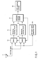
- FIG. 1 is a block diagram illustrating the configuration of a VOR monitoring receiving apparatus according to an embodiment of the invention.
- a VOR field signal output from a VOR apparatus (not shown) and received by a monitor receiving antenna 11, and a self-check signal generated by a self-check signal generation circuit 14 are selectively supplied to first and second monitoring receiving circuits 15 and 16 via first and second switches 12 and 13, respectively.
- the monitor output results of the first and second monitoring receiving circuits 15 and 16 are supplied to a VOR monitor controller 18 via a monitoring receiving controller 17, where abnormality detection of the VOR apparatus is executed.
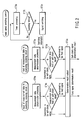
- FIG. 2 is a flowchart illustrating the procedure of processes performed by the VOR monitoring receiving apparatus of the embodiment.
- a VOR field signal is input to one of the first and second monitoring receiving circuits 15 and 16, thereby executing measurement data determination processing (steps ST3a and ST4a).
- the monitoring receiving controller 17 measures a preset time (step ST2a). If the preset time has elapsed, the process is shifted from step ST2b to step ST2c, where the monitoring receiving controller 17 switches the signal input monitoring receiving circuit so that the monitoring receiving circuit to which a VOR field signal has been supplied so far will receive a self-check signal. As a result, the monitoring receiving circuits 15 and 16 can continue their monitoring receiving operations.
- the monitoring receiving controller 17 determines whether each of the outputs of the monitoring receiving circuits 15 and 16 is a field determination result or self-check result, and outputs the determination result to the VOR monitor controller 18 (step ST5a).
- the monitoring receiving circuit 15 receives the signals shown in FIG. 3A .
- the switches 12 and 13 switch the signals, input to the first and second monitoring receiving circuits 15 and 16, to the field signal and self-check signal, respectively, or vice versa.
- the above operation is performed in units of preset times in accordance with a switch control signal output from the monitoring receiving controller 17.
- the monitoring receiving circuit 15 receives the signals shown in FIG. 3A
- the monitoring receiving circuit 16 receives the signals shown in FIG. 3C .
- the monitoring receiving circuits 15 and 16 can continue their monitoring receiving operations.
- the monitoring receiving circuit 15 outputs the signals shown in FIG. 3B , and the monitoring receiving circuit 16 outputs the signals shown in FIG. 3D . These output signals are input to the VOR monitor controller 18.
- the switching times of the switches 12 and 13 can be arbitrarily set by a user in the monitoring receiving controller 17.
- two monitoring receiving circuits 15 and 16 are employed, and the switches 12 and 13 are made to perform switching in units of preset times so that the switching timings of the field signal and self-check signal input to each monitoring receiving circuit do not overlap each other so as to continuously supply the field signal.
- the field signals can be monitored continuously while self-checking the monitoring receiving circuits 15 and 16, with the result that abnormality detection of the VOR device can be performed more reliably.
- the present invention is not limited to the above-described embodiment, but may be modified in various ways without departing from the scope.
- Various inventions can be realized by appropriately combining the structural elements disclosed in the embodiments. For instance, some of the disclosed structural elements may be deleted.
Landscapes
- Engineering & Computer Science (AREA)
- Computer Networks & Wireless Communication (AREA)
- Physics & Mathematics (AREA)
- General Physics & Mathematics (AREA)
- Radar, Positioning & Navigation (AREA)
- Remote Sensing (AREA)
- Alarm Systems (AREA)
- Monitoring And Testing Of Transmission In General (AREA)
Abstract
Description
- The present invention relates to a VOR monitoring receiving apparatus and VOR monitor receiving method for monitoring the operation of a very high frequency omnidirectional radio range (VOR) apparatus.
- Airports in various regions employ various types of equipment for assisting the landing of airplanes, such as passenger airplanes. For instance, a very high frequency omnidirectional radio range (VOR) device is included in the equipment (see, for example, radar technologies disclosed by Institute of Electronics, Information and Communication Engineers). VOR apparatuses provide direction information to airplanes utilizing the horizontal polarization of a signal with a frequency of 112 to 118 MHz.
- To utilize the VOR apparatuses, they are required to operate stably. In the prior art, a VOR monitoring receiving apparatus is used, which receives a field signal from a VOR apparatus and monitors it to confirm the operation of the VOR apparatus. To confirm whether a built-in monitoring receiving circuit is operating normally, the VOR monitoring receiving apparatus uses a self-check signal.
- While the built-in monitoring receiving circuit is receiving a self-check signal, the VOR monitoring receiving device cannot receive a to-be-monitored field signal, and hence cannot detect any abnormality. In light of this, a technique of displaying, on a single screen, a window for a field signal and a window.for a self-check signal may be employed as in standard computers (see, for example, Jpn. Pat. Appln. KOKAI Publication No.
5-204584 - It is an object of the invention to provide a VOR monitoring receiving apparatus capable of both self-checking a monitoring receiving circuit and monitoring a field signal, and a VOR monitor receiving method for enabling the apparatus to execute them.
- In accordance with one aspect of the invention, there is provided a VOR monitoring receiving apparatus comprising: a receiving circuit configured to receive a field signal from a VOR apparatus, and output content of the field signal to a plurality of signal systems; a first monitoring receiving circuit provided in a first signal system included in the plurality of signal systems, and configured to monitor the content of the field signal; a second monitoring receiving circuit provided in a second signal system included in the plurality of signal systems, and configured to monitor the content of the field signal; a self-check signal generator configured to generate a self-check signal necessary to confirm whether the first and second monitoring receiving circuits normally operate; a VOR monitoring controller configured to detect an abnormality of the VOR apparatus based on monitoring results of the first and second monitoring receiving circuits; a switch configured to perform switching to alternately output the field signal and the self-check signal to the first and second signal systems; and a switch controller configured to control the switch to perform switching whenever a preset time elapses.
- In accordance with another aspect of the invention, there is provided a VOR monitoring receiving method for receiving a field signal from a VOR apparatus, monitoring content of the field signal using at least one signal system included in the plurality of signal systems, and inputting a monitoring result to a VOR monitoring controller to detect an abnormality of the VOR apparatus, comprising: generating a self-check signal necessary to confirm whether a first monitoring receiving circuit and a second monitoring receiving circuit normally operate, which are provided in a first signal system and a second signal system included in the plurality of signal systems, respectively; alternately outputting the field signal and the self-check signal to the first and second signal systems whenever a preset time elapses; causing the first and second monitoring receiving circuits to perform monitoring and output monitoring results to the VOR monitoring controller.
- The invention can be more fully understood from the following detailed description when taken in conjunction with the accompanying drawings, in which:
-
FIG. 1 is a block diagram illustrating the configuration of a VOR monitoring receiving apparatus according to an embodiment of the invention; -
FIG. 2 is a flowchart illustrating the procedure of processes performed by the VOR monitoring receiving apparatus of the embodiment; -
FIG. 3A is a view of signal timing useful in explaining the signal input operation of a first monitoring receiving circuit employed in the embodiment; -
FIG. 3B is a view of signal timing useful in explaining the signal output operation of the first monitoring receiving circuit employed in the embodiment; -
FIG. 3C is a view of signal timing useful in explaining the signal input operation of a second monitoring receiving circuit employed in the embodiment; -and -
FIG. 3D is a view of signal timing useful in explaining the signal output operation of the second monitoring receiving circuit employed in the embodiment. - An embodiment of the invention will be described in detail with reference to the accompanying drawings.
-
FIG. 1 is a block diagram illustrating the configuration of a VOR monitoring receiving apparatus according to an embodiment of the invention. - In
FIG. 1 , a VOR field signal output from a VOR apparatus (not shown) and received by amonitor receiving antenna 11, and a self-check signal generated by a self-checksignal generation circuit 14 are selectively supplied to first and secondmonitoring receiving circuits second switches monitoring receiving circuits VOR monitor controller 18 via a monitoringreceiving controller 17, where abnormality detection of the VOR apparatus is executed. - The operation of the above-mentioned structure will now be described.
FIG. 2 is a flowchart illustrating the procedure of processes performed by the VOR monitoring receiving apparatus of the embodiment. - In the VOR monitoring receiving apparatus constructed as above, a VOR field signal is input to one of the first and second
monitoring receiving circuits monitoring receiving controller 17 measures a preset time (step ST2a). If the preset time has elapsed, the process is shifted from step ST2b to step ST2c, where the monitoring receivingcontroller 17 switches the signal input monitoring receiving circuit so that the monitoring receiving circuit to which a VOR field signal has been supplied so far will receive a self-check signal. As a result, themonitoring receiving circuits receiving controller 17 determines whether each of the outputs of themonitoring receiving circuits - Referring then to
FIG. 3 , the above operation will be described in more detail. Themonitoring receiving circuit 15 receives the signals shown inFIG. 3A . When the preset time has elapsed, theswitches monitoring receiving circuits - The above operation is performed in units of preset times in accordance with a switch control signal output from the
monitoring receiving controller 17. As a result, the monitoring receivingcircuit 15 receives the signals shown inFIG. 3A , and themonitoring receiving circuit 16 receives the signals shown inFIG. 3C . Thus, themonitoring receiving circuits - The
monitoring receiving circuit 15 outputs the signals shown inFIG. 3B , and themonitoring receiving circuit 16 outputs the signals shown inFIG. 3D . These output signals are input to theVOR monitor controller 18. - The switching times of the
switches receiving controller 17. - As described above, in the embodiment, two
monitoring receiving circuits switches - By virtue of this structure, the field signals can be monitored continuously while self-checking the
monitoring receiving circuits - The present invention is not limited to the above-described embodiment, but may be modified in various ways without departing from the scope. Various inventions can be realized by appropriately combining the structural elements disclosed in the embodiments. For instance, some of the disclosed structural elements may be deleted.
Claims (6)
- A VOR (Very High Frequency Omnidirectional Radio Range) monitoring receiving apparatus characterized by comprising:a receiving circuit (11) configured to receive a field signal from a VOR apparatus, and output content of the field signal to a plurality of signal systems;a first monitoring receiving circuit (15) provided in a first signal system included in the plurality of signal systems, and configured to monitor the content of the field signal;a second monitoring receiving circuit (16) provided in a second signal system included in the plurality of signal systems, and configured to monitor the content of the field signal;a self-check signal generator (14) configured to generate a self-check signal necessary to confirm whether the first and second monitoring receiving circuits (15, 16) normally operate;a VOR monitoring controller (18) configured to detect an abnormality of the VOR apparatus based on monitoring results of the first and second monitoring receiving circuits (15, 16);a switch (12, 13) configured to perform switching to alternately output the field signal and the self-check signal to the first and second signal systems; anda switch controller (17) configured to control the switch (12, 13) to perform switching whenever a preset time elapses.
- The VOR monitoring receiving apparatus according to claim 1, characterized in that the switch controller (17) determines whether a monitoring result from each of the first and second monitoring receiving circuits (15, 16) indicates monitored content of the field signal or monitored content of the self-check signal, outputs a determination result to the VOR monitoring controller (18), and controls the switch (12, 13) to perform switching whenever the preset time elapses.
- The VOR monitoring receiving apparatus according to claim 1, characterized in that the preset time can be arbitrarily set.
- A VOR (Very High Frequency Omnidirectional Radio Range) monitoring receiving method for receiving a field signal from a VOR apparatus, monitoring content of the field signal using at least one signal system included in the plurality of signal systems, and inputting a monitoring result to a VOR monitoring controller (18) to detect an abnormality of the VOR apparatus, characterized by comprising:generating a self-check signal necessary to confirm whether a first monitoring receiving circuit (15) and a second monitoring receiving circuit (16) normally operate, which are provided in a first signal system and a second signal system included in the plurality of signal systems, respectively;alternately outputting the field signal and the self-check signal to the first and second signal systems whenever a preset time elapses;causing the first and second monitoring receiving circuits (15, 16) to perform monitoring and output monitoring results to the VOR monitoring controller (18).
- The VOR monitoring receiving method according to claim 4, characterized by further comprising determining whether the monitoring result from each of the first and second monitoring receiving circuits (15, 16) indicates monitored content of the field signal or monitored content of the self-check signal, and outputting a determination result to the VOR monitoring controller (18).
- The VOR monitoring receiving method according to claim 4, characterized in that the preset time can be arbitrarily set.
Applications Claiming Priority (1)
| Application Number | Priority Date | Filing Date | Title |
|---|---|---|---|
| JP2007016632A JP2008183929A (en) | 2007-01-26 | 2007-01-26 | VOR monitor receiving apparatus and VOR monitor receiving method |
Publications (1)
| Publication Number | Publication Date |
|---|---|
| EP1953562A1 true EP1953562A1 (en) | 2008-08-06 |
Family
ID=39387386
Family Applications (1)
| Application Number | Title | Priority Date | Filing Date |
|---|---|---|---|
| EP08250211A Withdrawn EP1953562A1 (en) | 2007-01-26 | 2008-01-16 | VOR monitoring receiving apparatus and VOR monitor receiving method |
Country Status (4)
| Country | Link |
|---|---|
| US (1) | US7791531B2 (en) |
| EP (1) | EP1953562A1 (en) |
| JP (1) | JP2008183929A (en) |
| CN (1) | CN101231334A (en) |
Families Citing this family (12)
| Publication number | Priority date | Publication date | Assignee | Title |
|---|---|---|---|---|
| DE10238723A1 (en) | 2002-08-23 | 2004-03-11 | Bayer Ag | Phenyl substituted pyrazolyprimidines |
| JP2008183929A (en) * | 2007-01-26 | 2008-08-14 | Toshiba Corp | VOR monitor receiving apparatus and VOR monitor receiving method |
| JP5498392B2 (en) * | 2007-11-30 | 2014-05-21 | ベーリンガー インゲルハイム インターナショナル ゲゼルシャフト ミット ベシュレンクテル ハフツング | 1,5-Dihydro-pyrazolo [3,4-D] pyrimidin-4-one derivatives and their use as PDE9A modulators for the treatment of CNS disorders |
| UA105362C2 (en) | 2008-04-02 | 2014-05-12 | Бьорингер Ингельхайм Интернациональ Гмбх | 1-heterocyclyl-1, 5-dihydro-pyrazolo [3, 4-d] pyrimidin-4-one derivatives and their use as pde9a modulators |
| CN102143965A (en) | 2008-09-08 | 2011-08-03 | 贝林格尔.英格海姆国际有限公司 | Pyrazolopyrimidines and their use for the treatment of CNS disorders |
| JP4735708B2 (en) * | 2008-11-19 | 2011-07-27 | 株式会社デンソー | Vehicle receiver system |
| PT2414363E (en) * | 2009-03-31 | 2014-02-26 | Boehringer Ingelheim Int | 1-heterocyclyl-1,5-dihydro-pyrazolo[3,4-d]pyrimidin-4-one derivatives and their use as pde9a modulators |
| AR077859A1 (en) * | 2009-08-12 | 2011-09-28 | Boehringer Ingelheim Int | COMPOUNDS FOR THE TREATMENT OF CNS DISORDERS |
| UA110347C2 (en) | 2010-08-12 | 2015-12-25 | Бьорінгер Інгельхайм Інтернаціональ Гмбх | DERIVATIVES OF 6-CYCLOALKYL-1,5-DIHYDROPYRAZOLE $ 3,4-d] PYRIMIDIN-4-ONE AND THEIR USE AS PDE9A INHIBITORS |
| US8809345B2 (en) | 2011-02-15 | 2014-08-19 | Boehringer Ingelheim International Gmbh | 6-cycloalkyl-pyrazolopyrimidinones for the treatment of CNS disorders |
| JP2014052239A (en) * | 2012-09-06 | 2014-03-20 | Toshiba Corp | D-vor device, and program |
| WO2018153887A1 (en) * | 2017-02-23 | 2018-08-30 | Boehringer Ingelheim International Gmbh | New medical use of compound iii |
Citations (4)
| Publication number | Priority date | Publication date | Assignee | Title |
|---|---|---|---|---|
| US4506332A (en) * | 1981-01-30 | 1985-03-19 | International Standard Electric Corporation | Facility for monitoring the level of a radio-frequency signal |
| GB2150781A (en) * | 1983-12-02 | 1985-07-03 | Int Standard Electric Corp | Navigation system ground station |
| US4739351A (en) * | 1986-11-18 | 1988-04-19 | Hazeltine Corporation | Verification of on-line fault monitor performance |
| EP0429972A2 (en) * | 1989-11-23 | 1991-06-05 | Alcatel SEL Aktiengesellschaft | Apparatus and method for monitoring navigation equipment |
Family Cites Families (8)
| Publication number | Priority date | Publication date | Assignee | Title |
|---|---|---|---|---|
| US3818476A (en) * | 1972-06-27 | 1974-06-18 | Tull Aviation Corp | Navigation aid transmitter-monitor system |
| US4061297A (en) * | 1975-06-06 | 1977-12-06 | Airdata Inc. | Approach range monitor |
| DE2924847A1 (en) * | 1979-06-20 | 1981-01-22 | Standard Elektrik Lorenz Ag | MICROWAVE LANDING SYSTEM THAT WORKS BY THE JET SWIVELING PROCESS |
| JPH0381611A (en) * | 1989-08-24 | 1991-04-08 | Mitsubishi Heavy Ind Ltd | Magnetizing signal generator |
| JPH05204584A (en) | 1992-01-27 | 1993-08-13 | Ricoh Co Ltd | Window display device and window display method |
| FR2742232B1 (en) * | 1995-12-08 | 1998-02-06 | Sextant Avionique | METHOD AND DEVICE FOR TESTING RADIO-NAVIGATION INSTRUMENTS USING STANDARD SIGNAL MEASUREMENT AND GENERATING APPARATUS |
| DE60004401D1 (en) * | 1999-12-15 | 2003-09-11 | United Parcel Service Inc | METHOD AND DEVICES FOR MONITORING SEVERAL CHANNELS IN A PRE-RECEIVER |
| JP2008183929A (en) * | 2007-01-26 | 2008-08-14 | Toshiba Corp | VOR monitor receiving apparatus and VOR monitor receiving method |
-
2007
- 2007-01-26 JP JP2007016632A patent/JP2008183929A/en not_active Abandoned
-
2008
- 2008-01-16 EP EP08250211A patent/EP1953562A1/en not_active Withdrawn
- 2008-01-23 CN CN200810008530.5A patent/CN101231334A/en active Pending
- 2008-01-24 US US12/019,199 patent/US7791531B2/en not_active Expired - Fee Related
Patent Citations (4)
| Publication number | Priority date | Publication date | Assignee | Title |
|---|---|---|---|---|
| US4506332A (en) * | 1981-01-30 | 1985-03-19 | International Standard Electric Corporation | Facility for monitoring the level of a radio-frequency signal |
| GB2150781A (en) * | 1983-12-02 | 1985-07-03 | Int Standard Electric Corp | Navigation system ground station |
| US4739351A (en) * | 1986-11-18 | 1988-04-19 | Hazeltine Corporation | Verification of on-line fault monitor performance |
| EP0429972A2 (en) * | 1989-11-23 | 1991-06-05 | Alcatel SEL Aktiengesellschaft | Apparatus and method for monitoring navigation equipment |
Also Published As
| Publication number | Publication date |
|---|---|
| CN101231334A (en) | 2008-07-30 |
| US7791531B2 (en) | 2010-09-07 |
| US20090121919A1 (en) | 2009-05-14 |
| JP2008183929A (en) | 2008-08-14 |
Similar Documents
| Publication | Publication Date | Title |
|---|---|---|
| US7791531B2 (en) | VOR monitoring receiving apparatus and VOR monitor receiving method | |
| KR102021920B1 (en) | System and method for synchronized triggering of test equipment for testing mimo transceivers | |
| JP5220873B2 (en) | Wafer inspection system | |
| CN106569070B (en) | The EMI localization method and device of television set | |
| EP3842837A2 (en) | Method and apparatus for using dual-polarization antenna | |
| JP6288957B2 (en) | Electromagnetic noise detector | |
| US20110267292A1 (en) | Method for simultaneously operating multiple pointers on electromagnetic position detection apparatus | |
| JP6390192B2 (en) | Partial discharge detection device and fault self-diagnosis method of partial discharge detection device | |
| JP5772024B2 (en) | Takan ground device and received signal monitoring method used in the device | |
| RU2643672C1 (en) | Multi-zone metal detector | |
| KR102662149B1 (en) | Method And Apparatus for Acquisition Data for Electric Power System | |
| US10291876B2 (en) | Method of power signal detection for set top box devices | |
| JP5038708B2 (en) | DVOR apparatus and sideband antenna abnormality detection method | |
| US11061077B2 (en) | Parallel trigger model for test and measurement instruments | |
| WO2015075707A4 (en) | Reference signal generation redundancy in distributed antenna systems (das), and related devices and methods | |
| RU177858U1 (en) | Multi-zone metal detector | |
| KR20070021798A (en) | Electromagnetic wave measuring device | |
| CN111274069B (en) | Data processing method and device | |
| JP4080463B2 (en) | Receiver inspection system | |
| JP6171394B2 (en) | Radar apparatus and tracking control method | |
| KR100886614B1 (en) | Semiconductor product test device with touch panel | |
| KR101648508B1 (en) | Scanning system and result processing method thereof | |
| JP2011145116A (en) | Heterodyne detection of beam-type detector | |
| RU32888U1 (en) | Cliff radar air traffic control system | |
| US20150309909A1 (en) | Electronic device and fault analysing method |
Legal Events
| Date | Code | Title | Description |
|---|---|---|---|
| PUAI | Public reference made under article 153(3) epc to a published international application that has entered the european phase |
Free format text: ORIGINAL CODE: 0009012 |
|
| 17P | Request for examination filed |
Effective date: 20080124 |
|
| AK | Designated contracting states |
Kind code of ref document: A1 Designated state(s): AT BE BG CH CY CZ DE DK EE ES FI FR GB GR HR HU IE IS IT LI LT LU LV MC MT NL NO PL PT RO SE SI SK TR |
|
| AX | Request for extension of the european patent |
Extension state: AL BA MK RS |
|
| 17Q | First examination report despatched |
Effective date: 20080915 |
|
| AKX | Designation fees paid |
Designated state(s): DE FR IT |
|
| RBV | Designated contracting states (corrected) |
Designated state(s): FR GB IT |
|
| REG | Reference to a national code |
Ref country code: DE Ref legal event code: 8566 |
|
| STAA | Information on the status of an ep patent application or granted ep patent |
Free format text: STATUS: THE APPLICATION IS DEEMED TO BE WITHDRAWN |
|
| 18D | Application deemed to be withdrawn |
Effective date: 20120801 |