EP1953495A2 - Coordinate measuring auxiliary tool and coordinate measuring probe - Google Patents
Coordinate measuring auxiliary tool and coordinate measuring probe Download PDFInfo
- Publication number
- EP1953495A2 EP1953495A2 EP08100612A EP08100612A EP1953495A2 EP 1953495 A2 EP1953495 A2 EP 1953495A2 EP 08100612 A EP08100612 A EP 08100612A EP 08100612 A EP08100612 A EP 08100612A EP 1953495 A2 EP1953495 A2 EP 1953495A2
- Authority
- EP
- European Patent Office
- Prior art keywords
- coordinate measuring
- probe
- auxiliary tool
- ball
- shaped body
- Prior art date
- Legal status (The legal status is an assumption and is not a legal conclusion. Google has not performed a legal analysis and makes no representation as to the accuracy of the status listed.)
- Granted
Links
Images



Classifications
-
- G—PHYSICS
- G01—MEASURING; TESTING
- G01B—MEASURING LENGTH, THICKNESS OR SIMILAR LINEAR DIMENSIONS; MEASURING ANGLES; MEASURING AREAS; MEASURING IRREGULARITIES OF SURFACES OR CONTOURS
- G01B5/00—Measuring arrangements characterised by the use of mechanical techniques
- G01B5/004—Measuring arrangements characterised by the use of mechanical techniques for measuring coordinates of points
- G01B5/008—Measuring arrangements characterised by the use of mechanical techniques for measuring coordinates of points using coordinate measuring machines
- G01B5/012—Contact-making feeler heads therefor
Definitions
- the present invention relates to a coordinate measuring auxiliary tool, a coordinate measuring probe and a coordinate measuring machine, more particularly, to a coordinate measuring auxiliary tool, which is suitable for a ball probe of a manual operation type three-dimensional coordinate measuring machine or digitizer and capable of easily and accurately measuring a thin plate-shaped object to be measured, a coordinate measuring probe equipped with the coordinate measuring auxiliary tool, and a coordinate measuring machine equipped with the coordinate measuring probe.
- a probe having, at the tip, a ball for contact with an object to be measured being relatively moved manually in a three-dimensional direction, a central coordinate value of the ball being measured at the moment or while the ball being brought into contact or making contact with the object to be measured, and then offset processing is executed for the radius of the ball with respect to the central coordinate value of the ball and a contact position of the ball and the object to be measured can be measured.
- a direction of offset with respect to the measured central coordinate of the ball is required to be pre-specified or to be geometrically calculated with use of measured central coordinate values of a plurality of balls.
- the ball is guided and brought into contact with three positions of the inside of the hole and each central coordinate value is measured.
- the center and the radius of a hole circle is obtained by applying the three coordinate values to a circle circulation, and the radius of the hole can be obtained by adding the calculated radius to the radius of the ball.
- Patent Document 1 Japanese Published Unexamined Patent Application No. H10-62150
- Figs. 2 to 5 in Japanese Published Unexamined Patent Application No. 2005-147673 Patent Document 2
- a 3/4 spherical probe formed of the ball 2 which is partially notched to the center C is used, and the center C of the ball 2 is directly made to profile the work 9.
- the reference numeral 11 denotes a push button switch which is provided on a probe body 10 and used for storing current position data only when being pushed.
- V-shaped probe having a V-shaped tip has been put to practical use.
- the present invention was made in order to solve the above problems, and aims at providing a coordinate measuring auxiliary tool which is capable of easily and accurately measuring a thin plate-shaped object to be measured in measuring by a manual operation type three-dimensional coordinate measuring machine or digitizer, a coordinate measuring probe equipped with the coordinate measuring auxiliary tool, and a coordinate measuring machine equipped with the coordinate measuring probe.
- the coordinate measuring auxiliary tool of the present invention solves the above problems, including a cylindrical body attached to an outer circumference of the coordinate measuring probe and means for positioning and fixing a cylindrical shaped body to the tip of the probe.
- making at least apart of the cylindrical shaped body transparent allows an operator to easily check the engagement state of the object to be measured and the tip of the probe.
- a means for positioning and fixing the cylindrical body to the tip of the probe is provided on an outer cylinder of the double-cylinder and an inner cylinder screw-engaged with the outer cylinder is axially rotated, thereby it is possible to adjust a position of the cylindrical body to the tip of the probe.
- an end plate or conical part may be provided at the top end of the cylindrical shaped body.
- the present invention provides a coordinate measuring probe equipped with the coordinate measuring auxiliary tool.
- the present invention provides a coordinate measuring machine equipped with the coordinate measuring probe.
- the tip of the coordinate measuring probe e.g. center of the ball
- the tip of the coordinate measuring probe can be brought into contact with a part to measured at a specified height from the surface of the sheet metal. Accordingly, the maximum circle part of a ball or the like is securely brought into contact with a position to be measured, and high accuracy measurement can be easily performed. Further, variations in measurements by operators can be prevented from occurring. Furthermore, the tip of the probe can be protected.
- Embodiments of the present invention will be described below in detail, the embodiments being adapted to a ball probe of an arm type articulated coordinate measuring machine (called a three-dimensional digitizer).
- An arm-type articulated coordinate measuring machine 50 to which the present invention is applied, includes a pole 58 vertically erected on a base 59 fixed to a working table or the like.
- the pole 58 is connected to an end of a second arm 57 via a third articulation 55 in which a rotary encoder (not shown) is built, the third articulation being capable of freely rotating in biaxial directions and the rotary encoder being capable of detecting each of the rotation angles.
- the other end of the second arm 57 is connected to an end of a first arm 56 via a second articulation 54 similar to the third articulation 55.
- the other end of the first arm 56 is connected to a probe head 52 via a first articulation 53 similar to the second articulation 54.
- a tip of the probe head 52 is provided with a ball probe 51 of the present invention.
- an operator grips and operates the probe head 52 to make the ball probe 51 approach an object to be measured from all directions, and bring the probe into contact with the object at a free angle.
- the ball probe 51 is equipped with a coordinate measuring auxiliary tool 60 including a cylindrical body 62 attached to an outer circumference of the ball probe 51 and a clamping mechanism 70 for positioning and fixing the cylindrical body 62 to a tip of the ball probe 51.
- the cylindrical body 62 is constituted by a transparent body such as acrylic resin, and measurement can be performed while checking the engagement state of a ball at the tip of the ball probe 51 and a work 9 which is the object to be measured. Moreover, the cylindrical body 62 may be made of opaque metal.
- Fig. 5 shows a state that the tip ball of the ball probe 51 is made to contact with the work 9.
- the clamping mechanism 70 is loosened via a knob 72 in advance and the cylindrical body 62 is vertically moved so that the center face of the ball is positioned to a center line of the work 9 when the top end (lower end in Fig. 5 ) of the cylindrical body 62 is in contact with the surface of the work 9.
- the operator moves the ball probe 51 to a target measurement point of the work 9 by manual operation.
- the top end of the cylindrical body 62 hits the surface of the work 9 while the posture of ball probe 51 is adjusted so that the center axis of the probe head 52 becomes approximately perpendicular to the surface of the work 9.
- the center face of the ball is level with the center line of the work 9, and a coordinate of this point may be captured.
- FIG. 6 A second embodiment of the present invention is shown in Fig. 6 .
- a double cylinder including an outer cylinder 80 and an inner cylinder 82 is employed as a cylindrical shaped body, the coordinate measuring auxiliary tool 60 is fixed to the ball probe 51 by the clamping mechanism 70 provided on the outer cylinder 80, and the inner cylinder 82 screw-engaging with the outer cylinder 80 is rotated around the axis, thereby a positional relationship between the ball and the top end of the cylindrical body (inner cylinder 82) can be adjusted.
- a scale 84 is formed on a surface of the inner cylinder 82.
- a lower end of the ball is made level with a lower end surface of the inner cylinder 82 to clamp them by the clamping mechanism 70.
- the scale 84 is set to a negative position by the radius of the ball.
- the inner cylinder 82 is rotated with respect to the outer cylinder 80, the scale 84 is raised to a positive position by half of the thickness (e.g. 0.5 to 2 mm) of the work 9, and thus the lower end surface of the inner cylinder 82 can be set at a predetermined height from the center of the ball.
- the thickness e.g. 0.5 to 2 mm
- the scale 84 is provided, and thus height adj ustment can be easily performed. Moreover, the scale may be omitted so that adjustment can be visually performed.
- a mechanism for engagement and movement of the outer cylinder 80 and inner cylinder 82 is not limited to screw tightening, and another mechanism, e.g. a cylindrical cam, applicable for parallel movement is possible.
- an end plate 64 is provided at a lower end of the cylindrical body 62, and thus measurement of the flat plate-shaped work 9 can be made easy.
- a conical part 66 is provided at the lower end of the cylindrical body 62, and thus measurement of a bent plate-shaped work 9' can be made easy.
- the shape of the cylindrical body is not limited to a right circular cylinder, and as shown in Fig. 11 showing a fifth embodiment, any hollow shape having a flat lower end such as a square tube 68 is applicable.
- a stepped cylinder 63 is employed, interference between the cylinder and the work can be reduced, and the cylinder is effective for a long stylus. Further, if a flange 63F is provided on an opening of the top end, contact area of the cylinder and the work is increased, and thus, the posture of the cylinder can be further stabilized.
- an application target of the present invention is not limited to this.
- the present invention can be similarly applied to a ball probe of a three-dimensional coordinate measuring machine including a gate type or C-shaped frame, and a touch signal probe.
- the present invention is applicable in the case of not only measuring a sheet metal-shaped work but also performing a depth specified measurement of a cylinder hole having a same height to be measured with the three-dimensional coordinate measuring machine.
Landscapes
- Physics & Mathematics (AREA)
- General Physics & Mathematics (AREA)
- A Measuring Device Byusing Mechanical Method (AREA)
Abstract
Description
- The present invention relates to a coordinate measuring auxiliary tool, a coordinate measuring probe and a coordinate measuring machine, more particularly, to a coordinate measuring auxiliary tool, which is suitable for a ball probe of a manual operation type three-dimensional coordinate measuring machine or digitizer and capable of easily and accurately measuring a thin plate-shaped object to be measured, a coordinate measuring probe equipped with the coordinate measuring auxiliary tool, and a coordinate measuring machine equipped with the coordinate measuring probe.
- For example, in a manual operation type three-dimensional coordinate measuring machine, a probe having, at the tip, a ball for contact with an object to be measured being relatively moved manually in a three-dimensional direction, a central coordinate value of the ball being measured at the moment or while the ball being brought into contact or making contact with the object to be measured, and then offset processing is executed for the radius of the ball with respect to the central coordinate value of the ball and a contact position of the ball and the object to be measured can be measured. However, a direction of offset with respect to the measured central coordinate of the ball is required to be pre-specified or to be geometrically calculated with use of measured central coordinate values of a plurality of balls. For example, in the case where the object to be measured is a hole, the ball is guided and brought into contact with three positions of the inside of the hole and each central coordinate value is measured. Next, the center and the radius of a hole circle is obtained by applying the three coordinate values to a circle circulation, and the radius of the hole can be obtained by adding the calculated radius to the radius of the ball.
- However, in the case of a thin object, such as sheet metal, having a thickness smaller than the radius of the ball, the probe is required to be guided in the hole measurement so that the tip of the ball is brought into contact with the object to be measured. Therefore, workbecomes difficult and skill is required. Additionally, as shown in
Fig. 1 , with respect to awork 9 which is made of a thin steel plate, if aball 2 fixed at the tip of ashaft 3 of theprobe 1 is brought into contact with thework 9 and measurement is made at a deviated position such as ameasurement position 8 and not at ameasurement position 7 to which theball 2 should be made to contact, a problem such as a large measurement error may be caused. - In order to solve the problem, the applicant has proposed, as shown in
Fig. 2 or inFigs. 1 to 3 of Japanese Published Unexamined Patent Application No.H10-62150 mark 4 having a predetermined width is attached to the maximum outer circumference of theball 2 and serves as a standard of measurement. - Additionally, in
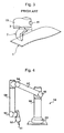
Figs. 2 to 5 in Japanese Published Unexamined Patent Application No.2005-147673 Fig. 3 , that a 3/4 spherical probe formed of theball 2 which is partially notched to the center C is used, and the center C of theball 2 is directly made to profile thework 9. InFig. 3 , thereference numeral 11 denotes a push button switch which is provided on aprobe body 10 and used for storing current position data only when being pushed. - Further, a V-shaped probe having a V-shaped tip has been put to practical use.
- However, in the technology disclosed in
patent document 1, an operator is required to visually position themark 4 of theball 2 to thework 9 and to entirely concentrate on that, and further, accurate positioning is not easy. - On the other hand, in the 3/4 spherical probe disclosed in
patent document 2 and the V-shaped probe, it is necessary to work a ball or a tip of a probe into a specific shape, and it is difficult to not only precisely work a center position but maintain the precision. Further, it is difficult to correct the center position (calibration) , and there remains a problem that the total cost increases. - The present invention was made in order to solve the above problems, and aims at providing a coordinate measuring auxiliary tool which is capable of easily and accurately measuring a thin plate-shaped object to be measured in measuring by a manual operation type three-dimensional coordinate measuring machine or digitizer, a coordinate measuring probe equipped with the coordinate measuring auxiliary tool, and a coordinate measuring machine equipped with the coordinate measuring probe.
- The coordinate measuring auxiliary tool of the present invention solves the above problems, including a cylindrical body attached to an outer circumference of the coordinate measuring probe and means for positioning and fixing a cylindrical shaped body to the tip of the probe.
- Here, making at least apart of the cylindrical shaped body transparent allows an operator to easily check the engagement state of the object to be measured and the tip of the probe.
- Additionally, by making it possible to adjust a position of the cylindrical shaped body with respect to the tip of the probe, measurement of objects having various thicknesses can be easily performed.
- Additionally, by adopting a double cylinder to the cylindrical shaped body, it is possible to adjust a position of one of the cylinders to the tip of the probe.
- Additionally, a means for positioning and fixing the cylindrical body to the tip of the probe is provided on an outer cylinder of the double-cylinder and an inner cylinder screw-engaged with the outer cylinder is axially rotated, thereby it is possible to adjust a position of the cylindrical body to the tip of the probe.
- Further, if a scale is provided, indicating displacement of one cylinder to another cylinder, it is possible to easily measure the objects to be measured having various thicknesses.
- Additionally, an end plate or conical part may be provided at the top end of the cylindrical shaped body.
- The present invention provides a coordinate measuring probe equipped with the coordinate measuring auxiliary tool.
- Additionally, the present invention provides a coordinate measuring machine equipped with the coordinate measuring probe.
- According to the present invention, since the coordinate measuring probe is moved while the end of the cylindrical shaped body of the coordinate measuring auxiliary tool is brought into contact with a surface of sheet metal, the tip of the coordinate measuring probe (e.g. center of the ball) can be brought into contact with a part to measured at a specified height from the surface of the sheet metal. Accordingly, the maximum circle part of a ball or the like is securely brought into contact with a position to be measured, and high accuracy measurement can be easily performed. Further, variations in measurements by operators can be prevented from occurring. Furthermore, the tip of the probe can be protected.
- These and other novel features and advantages of the present invention will become apparent from the following detailed description of preferred embodiments.
- The preferred embodiments will be described with reference to the drawings, wherein like elements have been denoted throughout the figures with like reference numerals, and wherein;
-
Fig. 1 is a front view for explaining a conventional problem. -
Fig. 2 is a front view showing a prior art disclosed inpatent document 1. -
Fig. 3 is a perspective view showing a prior art disclosed inpatent document 2. -
Fig. 4 is a perspective view of an example of an arm type articulated coordinate measuring machine to which the present invention is applied. -
Fig. 5 is a cross sectional view of a ball probe equipped with a coordinate measuring auxiliary tool of a first embodiment of the present invention. -
Fig. 6 is a cross sectional view of a ball probe equipped with a coordinate measuring auxiliary tool of a second embodiment of the present invention. -
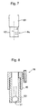
Fig. 7 is a side view of a scale of the second embodiment. -
Fig. 8 is a cross sectional view showing an adjustment state of the second embodiment. -
Fig. 9 is a cross sectional view of a ball probe equipped with a coordinate measuring auxiliary tool of a third embodiment of the present invention. -
Fig. 10 is a cross sectional view of a ball probe equipped with a coordinate measuring auxiliary tool of a fourth embodiment of the present invention. -
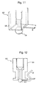
Fig. 11 is a cross sectional view of a ball probe equipped with a coordinate measuring auxiliary tool of a fifth embodiment of the present invention. -
Fig. 12 is a cross sectional view of a ball probe equipped with a coordinate measuring auxiliary tool of a sixth embodiment of the present invention. - Embodiments of the present invention will be described below in detail, the embodiments being adapted to a ball probe of an arm type articulated coordinate measuring machine (called a three-dimensional digitizer).
- An arm-type articulated
coordinate measuring machine 50, to which the present invention is applied, includes apole 58 vertically erected on abase 59 fixed to a working table or the like. Thepole 58 is connected to an end of asecond arm 57 via athird articulation 55 in which a rotary encoder (not shown) is built, the third articulation being capable of freely rotating in biaxial directions and the rotary encoder being capable of detecting each of the rotation angles. The other end of thesecond arm 57 is connected to an end of afirst arm 56 via asecond articulation 54 similar to thethird articulation 55. Further, the other end of thefirst arm 56 is connected to aprobe head 52 via afirst articulation 53 similar to thesecond articulation 54. A tip of theprobe head 52 is provided with aball probe 51 of the present invention. - Accordingly, an operator grips and operates the
probe head 52 to make theball probe 51 approach an object to be measured from all directions, and bring the probe into contact with the object at a free angle. - As shown in
Fig. 5 showing a first embodiment, theball probe 51 is equipped with a coordinate measuringauxiliary tool 60 including acylindrical body 62 attached to an outer circumference of theball probe 51 and aclamping mechanism 70 for positioning and fixing thecylindrical body 62 to a tip of theball probe 51. - The
cylindrical body 62 is constituted by a transparent body such as acrylic resin, and measurement can be performed while checking the engagement state of a ball at the tip of theball probe 51 and awork 9 which is the object to be measured. Moreover, thecylindrical body 62 may be made of opaque metal. - Next, a method for measuring the
sheet metal work 9 by use of the coordinate measuringauxiliary tool 60 will be described.Fig. 5 shows a state that the tip ball of theball probe 51 is made to contact with thework 9. - The
clamping mechanism 70 is loosened via aknob 72 in advance and thecylindrical body 62 is vertically moved so that the center face of the ball is positioned to a center line of thework 9 when the top end (lower end inFig. 5 ) of thecylindrical body 62 is in contact with the surface of thework 9. - The operator moves the
ball probe 51 to a target measurement point of thework 9 by manual operation. - Next, the top end of the
cylindrical body 62 hits the surface of thework 9 while the posture ofball probe 51 is adjusted so that the center axis of theprobe head 52 becomes approximately perpendicular to the surface of thework 9. Thus, the center face of the ball is level with the center line of thework 9, and a coordinate of this point may be captured. - A second embodiment of the present invention is shown in
Fig. 6 . - In the embodiment, in the coordinate measuring
auxiliary tool 60 of the first embodiment, a double cylinder including anouter cylinder 80 and aninner cylinder 82 is employed as a cylindrical shaped body, the coordinate measuringauxiliary tool 60 is fixed to theball probe 51 by theclamping mechanism 70 provided on theouter cylinder 80, and theinner cylinder 82 screw-engaging with theouter cylinder 80 is rotated around the axis, thereby a positional relationship between the ball and the top end of the cylindrical body (inner cylinder 82) can be adjusted. - As shown in
Fig. 7 , ascale 84 is formed on a surface of theinner cylinder 82. - In the embodiment, as shown in
Fig. 8 , a lower end of the ball is made level with a lower end surface of theinner cylinder 82 to clamp them by theclamping mechanism 70. At this time, thescale 84 is set to a negative position by the radius of the ball. - Next, the
inner cylinder 82 is rotated with respect to theouter cylinder 80, thescale 84 is raised to a positive position by half of the thickness (e.g. 0.5 to 2 mm) of thework 9, and thus the lower end surface of theinner cylinder 82 can be set at a predetermined height from the center of the ball. - In the embodiment, the
scale 84 is provided, and thus height adj ustment can be easily performed. Moreover, the scale may be omitted so that adjustment can be visually performed. - Additionally, a mechanism for engagement and movement of the
outer cylinder 80 andinner cylinder 82 is not limited to screw tightening, and another mechanism, e.g. a cylindrical cam, applicable for parallel movement is possible. - In the embodiment, since the top end of the cylindrical shaped body is a simply straight shape, the constitution is very simplified.
- Moreover, as shown in
Fig. 9 showing a third embodiment, anend plate 64 is provided at a lower end of thecylindrical body 62, and thus measurement of the flat plate-shapedwork 9 can be made easy. - Alternatively, as shown in
Fig. 10 showing a fourth embodiment, aconical part 66 is provided at the lower end of thecylindrical body 62, and thus measurement of a bent plate-shaped work 9' can be made easy. - The shape of the cylindrical body is not limited to a right circular cylinder, and as shown in
Fig. 11 showing a fifth embodiment, any hollow shape having a flat lower end such as asquare tube 68 is applicable. - Additionally, as shown in
Fig. 12 showing a sixth embodiment, if a steppedcylinder 63 is employed, interference between the cylinder and the work can be reduced, and the cylinder is effective for a long stylus. Further, if aflange 63F is provided on an opening of the top end, contact area of the cylinder and the work is increased, and thus, the posture of the cylinder can be further stabilized. - Moreover, though the present invention is applied to the arm type articulated coordinate measuring machine in all the embodiments, an application target of the present invention is not limited to this. For example, the present invention can be similarly applied to a ball probe of a three-dimensional coordinate measuring machine including a gate type or C-shaped frame, and a touch signal probe. Further, the present invention is applicable in the case of not only measuring a sheet metal-shaped work but also performing a depth specified measurement of a cylinder hole having a same height to be measured with the three-dimensional coordinate measuring machine.
Claims (10)
- A coordinate measuring auxiliary tool comprising:a cylindrical shaped body which is attached to an outer circumference of a coordinate measuring probe; andmeans for positioning and fixing the cylindrical shaped body to a tip of the probe.
- The coordinate measuring auxiliary tool according to claim 1, wherein
at least a part of the cylindrical shaped body is transparent. - The coordinate measuring auxiliary tool according to claim 1 or 2, wherein
a position of the cylindrical shaped body with respect to the tip of the probe can be adjusted. - The coordinate measuring auxiliary tool according to claim 3, wherein
the cylindrical shaped body is a double-cylinder, and a position of one of the cylinders with respect to the tip of the probe can be adjusted. - The coordinate measuring auxiliary tool according to claim 4, wherein
the means for positioning and fixing the cylindrical shaped body to the tip of the probe is provided on an outer cylinder of the double-cylinder, an inner cylinder screw-engaged with the outer cylinder is rotated around the axis, and thus a position of the inner cylinder to the tip of the probe can be adjusted. - The coordinate measuring auxiliary tool according to claim 4 or 5, wherein
a scale is provided which indicates displacement of one cylinder with respect to another cylinder of the double-cylinder. - The coordinate measuring auxiliary tool according to any of the preceding claims, wherein
an end plate is provided at a top end of the cylindrical shaped body. - The coordinate measuring auxiliary tool according to any of claims 1 to 6, wherein
a conical part is provided at the top end of the cylindrical shaped body. - A coordinate measuring probe equipped with the coordinate measuring auxiliary tool according to any one of claims 1 to 8.
- A coordinate measuring machine equipped with the coordinate measuring probe according to claim 9.
Applications Claiming Priority (1)
| Application Number | Priority Date | Filing Date | Title |
|---|---|---|---|
| JP2007025518A JP5179760B2 (en) | 2007-02-05 | 2007-02-05 | Coordinate measuring aid, coordinate measuring probe and coordinate measuring machine |
Publications (3)
| Publication Number | Publication Date |
|---|---|
| EP1953495A2 true EP1953495A2 (en) | 2008-08-06 |
| EP1953495A3 EP1953495A3 (en) | 2010-03-31 |
| EP1953495B1 EP1953495B1 (en) | 2017-07-26 |
Family
ID=39345445
Family Applications (1)
| Application Number | Title | Priority Date | Filing Date |
|---|---|---|---|
| EP08100612.4A Ceased EP1953495B1 (en) | 2007-02-05 | 2008-01-17 | Coordinate measuring auxiliary tool and coordinate measuring probe |
Country Status (4)
| Country | Link |
|---|---|
| US (1) | US7937848B2 (en) |
| EP (1) | EP1953495B1 (en) |
| JP (1) | JP5179760B2 (en) |
| CN (1) | CN101251377B (en) |
Families Citing this family (7)
| Publication number | Priority date | Publication date | Assignee | Title |
|---|---|---|---|---|
| KR101509657B1 (en) | 2013-12-09 | 2015-04-07 | 엘아이지넥스원 주식회사 | Device for setting up height and Adjustig method using the same |
| CN104568360B (en) * | 2014-12-25 | 2017-06-13 | 宁波吉利汽车研究开发有限公司 | A kind of device of the determination head contact point that experiment is whipped for automobile rear seat |
| CN104501691A (en) * | 2014-12-29 | 2015-04-08 | 天津大学 | Measuring and reading device for a water and soil erosion survey pin and using method thereof |
| JP6657005B2 (en) * | 2016-04-27 | 2020-03-04 | 株式会社ミツトヨ | Linear gauge |
| EP3531062A1 (en) * | 2018-02-26 | 2019-08-28 | Renishaw PLC | Coordinate positioning machine |
| CN113175907B (en) * | 2021-05-11 | 2024-09-20 | 广西玉柴机器股份有限公司 | Auxiliary tool for measuring protruding height of piston |
| CN116499406B (en) * | 2023-04-21 | 2025-11-11 | 中车青岛四方机车车辆股份有限公司 | Full-parameter measurement device and measurement method for internal threaded holes of parts |
Citations (2)
| Publication number | Priority date | Publication date | Assignee | Title |
|---|---|---|---|---|
| JPH1062150A (en) | 1996-08-19 | 1998-03-06 | Mitsutoyo Corp | Ball probe and coordinate measuring apparatus using ball probe |
| JP2005147673A (en) | 2003-11-11 | 2005-06-09 | Nissan Motor Co Ltd | Three-dimensional coordinate measuring probe and three-dimensional coordinate measuring apparatus using the probe |
Family Cites Families (26)
| Publication number | Priority date | Publication date | Assignee | Title |
|---|---|---|---|---|
| JPS58196404A (en) * | 1982-05-11 | 1983-11-15 | Mitsutoyo Mfg Co Ltd | Touch signal probe |
| JPS60168009U (en) * | 1984-04-16 | 1985-11-07 | 株式会社日研工作所 | Touch sensor for measurement |
| JPH0617766B2 (en) * | 1984-08-23 | 1994-03-09 | 株式会社ミツトヨ | Touch signal probe |
| DE3623614A1 (en) * | 1986-07-12 | 1988-01-14 | Zeiss Carl Fa | COORDINATE MEASURING DEVICE WITH A SWITCHING TYPE PROBE |
| EP0343237B1 (en) * | 1987-12-05 | 1992-06-17 | Renishaw plc | Apparatus for changing a sensing device |
| US5189808A (en) * | 1991-06-03 | 1993-03-02 | The Boeing Company | Measurement gauge |
| US5327657A (en) * | 1991-07-11 | 1994-07-12 | Renishaw Metrology Ltd. | Touch probe |
| CH687960A5 (en) * | 1993-02-18 | 1997-04-15 | Wild Plotter Ag C O Leica Ag | Machine tool plotter e.g. for self-adhesive foil |
| JPH06262419A (en) * | 1993-03-12 | 1994-09-20 | Brother Ind Ltd | Processing device for workpiece holder in automatic sewing machine |
| DE19605776A1 (en) * | 1996-02-16 | 1997-08-21 | Zeiss Carl Fa | Coordinate measuring device with a stylus, the orientation of which is adjustable |
| JP3474402B2 (en) * | 1997-07-17 | 2003-12-08 | 株式会社ミツトヨ | Measuring instrument |
| GB9724453D0 (en) * | 1997-11-20 | 1998-01-14 | Renishaw Plc | Measuring or positioning machine |
| JP2001066101A (en) * | 1999-08-26 | 2001-03-16 | Yasuo Tsubokura | Stick dimension measuring device |
| GB0019200D0 (en) * | 2000-08-05 | 2000-09-27 | Renishaw Plc | Bearing arrangement |
| DE10108774A1 (en) * | 2001-02-23 | 2002-09-05 | Zeiss Carl | Coordinate measuring device for probing a workpiece, probe for a coordinate measuring device and method for operating a coordinate measuring device |
| DE10118069A1 (en) * | 2001-04-11 | 2002-10-17 | Heidenhain Gmbh Dr Johannes | Length measuring probe has guide elements arranged between spring elements that bias probe pin |
| CN1250930C (en) * | 2001-06-18 | 2006-04-12 | 弗朗茨·海默机械制造两合公司 | Multi-coordinate sensing measuring device |
| US7044332B2 (en) * | 2002-03-27 | 2006-05-16 | Giegerich David K | Product contact sensor for an article handler |
| GB0221255D0 (en) * | 2002-09-13 | 2004-02-25 | Renishaw Plc | Touch Probe |
| DE10348887A1 (en) * | 2002-10-23 | 2004-05-13 | Carl Zeiss | Scanner head for measuring coordinates of surface of solid object has movable pin with ball end connected to magnet and Hall element |
| EP1443302B2 (en) * | 2003-01-29 | 2015-09-16 | Tesa Sa | Steerable feeler head |
| JP2007024821A (en) * | 2005-07-21 | 2007-02-01 | Chubu Electric Power Co Inc | Measuring device and measuring method for water conduit etc. |
| DE102005054593B4 (en) * | 2005-11-14 | 2018-04-26 | Immobiliengesellschaft Helmut Fischer Gmbh & Co. Kg | Measuring probe for measuring the thickness of thin layers |
| WO2007088570A2 (en) * | 2006-02-02 | 2007-08-09 | Metris Ipr Nv | Probe for gauging machines |
| JP3123799U (en) * | 2006-05-16 | 2006-07-27 | 株式会社ミツトヨ | Stylus protection jig |
| JP2009125853A (en) * | 2007-11-22 | 2009-06-11 | Murata Mach Ltd | Sensor |
-
2007
- 2007-02-05 JP JP2007025518A patent/JP5179760B2/en not_active Expired - Fee Related
-
2008
- 2008-01-17 EP EP08100612.4A patent/EP1953495B1/en not_active Ceased
- 2008-01-31 US US12/023,292 patent/US7937848B2/en active Active
- 2008-02-05 CN CN2008100951158A patent/CN101251377B/en not_active Expired - Fee Related
Patent Citations (2)
| Publication number | Priority date | Publication date | Assignee | Title |
|---|---|---|---|---|
| JPH1062150A (en) | 1996-08-19 | 1998-03-06 | Mitsutoyo Corp | Ball probe and coordinate measuring apparatus using ball probe |
| JP2005147673A (en) | 2003-11-11 | 2005-06-09 | Nissan Motor Co Ltd | Three-dimensional coordinate measuring probe and three-dimensional coordinate measuring apparatus using the probe |
Also Published As
| Publication number | Publication date |
|---|---|
| US20080184573A1 (en) | 2008-08-07 |
| CN101251377A (en) | 2008-08-27 |
| EP1953495A3 (en) | 2010-03-31 |
| EP1953495B1 (en) | 2017-07-26 |
| JP2008190994A (en) | 2008-08-21 |
| US7937848B2 (en) | 2011-05-10 |
| JP5179760B2 (en) | 2013-04-10 |
| CN101251377B (en) | 2012-01-04 |
Similar Documents
| Publication | Publication Date | Title |
|---|---|---|
| EP1953495B1 (en) | Coordinate measuring auxiliary tool and coordinate measuring probe | |
| CN111093902B (en) | Positioning device for machining points on workpieces | |
| US8363904B2 (en) | Offset amount calibrating method and surface texture measuring machine | |
| KR101673978B1 (en) | Robotic Arm System and Method for calibrating Parallelism of the Same | |
| US8654351B2 (en) | Offset amount calibrating method and surface profile measuring machine | |
| JP5294949B2 (en) | Measuring device for rotating body thickness etc. | |
| US7127824B2 (en) | Apparatus for detecting the position in space of a carriage moveable along a coordinate axis | |
| US10119848B2 (en) | Inspection machine and attachment jig therefor | |
| US7043846B2 (en) | Reference gauge for calibrating a measuring machine and method for calibrating a measuring machine | |
| US20040128846A1 (en) | Method and apparatus for measuring bent workpieces | |
| US3940854A (en) | Three axis precision measuring device | |
| US12018932B2 (en) | Determining the orientation of at least one object and method for relatively orienting rollers | |
| JP5210911B2 (en) | Shape measuring device | |
| JP4705792B2 (en) | Inter-axis angle correction method | |
| US10343041B2 (en) | Apparatus and method for measuring and adjusting a golf club loft and lie | |
| CN112589763B (en) | Steel pipe pile alignment welding tool and alignment welding method | |
| CN112665477A (en) | Detection tool and method for testing plane positioning accuracy of end effector | |
| JP2716249B2 (en) | Machine tool accuracy measurement method | |
| CN207180644U (en) | A kind of measurement apparatus of the base thickness of pivoting support bearing spacing block | |
| CN210741381U (en) | Endoscopic measuring device for linear dimension in workpiece hole | |
| CN219890375U (en) | Infrared ray detector for detection | |
| JP2005221320A (en) | Measurement head and probe | |
| CN216954344U (en) | Miniature angle groove angle measuring device | |
| CN213714187U (en) | Workpiece roundness detection experimental device | |
| KR0163560B1 (en) | Apparatus which measures a figure with inspection |
Legal Events
| Date | Code | Title | Description |
|---|---|---|---|
| PUAI | Public reference made under article 153(3) epc to a published international application that has entered the european phase |
Free format text: ORIGINAL CODE: 0009012 |
|
| AK | Designated contracting states |
Kind code of ref document: A2 Designated state(s): AT BE BG CH CY CZ DE DK EE ES FI FR GB GR HR HU IE IS IT LI LT LU LV MC MT NL NO PL PT RO SE SI SK TR |
|
| AX | Request for extension of the european patent |
Extension state: AL BA MK RS |
|
| PUAL | Search report despatched |
Free format text: ORIGINAL CODE: 0009013 |
|
| AK | Designated contracting states |
Kind code of ref document: A3 Designated state(s): AT BE BG CH CY CZ DE DK EE ES FI FR GB GR HR HU IE IS IT LI LT LU LV MC MT NL NO PL PT RO SE SI SK TR |
|
| AX | Request for extension of the european patent |
Extension state: AL BA MK RS |
|
| 17P | Request for examination filed |
Effective date: 20100921 |
|
| AKX | Designation fees paid |
Designated state(s): DE FR GB |
|
| 17Q | First examination report despatched |
Effective date: 20160727 |
|
| GRAP | Despatch of communication of intention to grant a patent |
Free format text: ORIGINAL CODE: EPIDOSNIGR1 |
|
| INTG | Intention to grant announced |
Effective date: 20170220 |
|
| GRAS | Grant fee paid |
Free format text: ORIGINAL CODE: EPIDOSNIGR3 |
|
| GRAA | (expected) grant |
Free format text: ORIGINAL CODE: 0009210 |
|
| AK | Designated contracting states |
Kind code of ref document: B1 Designated state(s): DE FR GB |
|
| REG | Reference to a national code |
Ref country code: GB Ref legal event code: FG4D |
|
| REG | Reference to a national code |
Ref country code: DE Ref legal event code: R096 Ref document number: 602008051271 Country of ref document: DE |
|
| REG | Reference to a national code |
Ref country code: FR Ref legal event code: PLFP Year of fee payment: 11 |
|
| REG | Reference to a national code |
Ref country code: DE Ref legal event code: R097 Ref document number: 602008051271 Country of ref document: DE |
|
| PLBE | No opposition filed within time limit |
Free format text: ORIGINAL CODE: 0009261 |
|
| STAA | Information on the status of an ep patent application or granted ep patent |
Free format text: STATUS: NO OPPOSITION FILED WITHIN TIME LIMIT |
|
| 26N | No opposition filed |
Effective date: 20180430 |
|
| PGFP | Annual fee paid to national office [announced via postgrant information from national office to epo] |
Ref country code: FR Payment date: 20210121 Year of fee payment: 14 |
|
| PGFP | Annual fee paid to national office [announced via postgrant information from national office to epo] |
Ref country code: GB Payment date: 20210121 Year of fee payment: 14 Ref country code: DE Payment date: 20210120 Year of fee payment: 14 |
|
| REG | Reference to a national code |
Ref country code: DE Ref legal event code: R119 Ref document number: 602008051271 Country of ref document: DE |
|
| GBPC | Gb: european patent ceased through non-payment of renewal fee |
Effective date: 20220117 |
|
| PG25 | Lapsed in a contracting state [announced via postgrant information from national office to epo] |
Ref country code: GB Free format text: LAPSE BECAUSE OF NON-PAYMENT OF DUE FEES Effective date: 20220117 Ref country code: DE Free format text: LAPSE BECAUSE OF NON-PAYMENT OF DUE FEES Effective date: 20220802 |
|
| PG25 | Lapsed in a contracting state [announced via postgrant information from national office to epo] |
Ref country code: FR Free format text: LAPSE BECAUSE OF NON-PAYMENT OF DUE FEES Effective date: 20220131 |