EP1953428A2 - Transmisssion - Google Patents
Transmisssion Download PDFInfo
- Publication number
- EP1953428A2 EP1953428A2 EP08250190A EP08250190A EP1953428A2 EP 1953428 A2 EP1953428 A2 EP 1953428A2 EP 08250190 A EP08250190 A EP 08250190A EP 08250190 A EP08250190 A EP 08250190A EP 1953428 A2 EP1953428 A2 EP 1953428A2
- Authority
- EP
- European Patent Office
- Prior art keywords
- motor
- control signal
- gear ratio
- vehicle
- low
- Prior art date
- Legal status (The legal status is an assumption and is not a legal conclusion. Google has not performed a legal analysis and makes no representation as to the accuracy of the status listed.)
- Granted
Links
Images


Classifications
-
- F—MECHANICAL ENGINEERING; LIGHTING; HEATING; WEAPONS; BLASTING
- F16—ENGINEERING ELEMENTS AND UNITS; GENERAL MEASURES FOR PRODUCING AND MAINTAINING EFFECTIVE FUNCTIONING OF MACHINES OR INSTALLATIONS; THERMAL INSULATION IN GENERAL
- F16H—GEARING
- F16H63/00—Control outputs from the control unit to change-speed- or reversing-gearings for conveying rotary motion or to other devices than the final output mechanism
- F16H63/02—Final output mechanisms therefor; Actuating means for the final output mechanisms
- F16H63/04—Final output mechanisms therefor; Actuating means for the final output mechanisms a single final output mechanism being moved by a single final actuating mechanism
- F16H63/06—Final output mechanisms therefor; Actuating means for the final output mechanisms a single final output mechanism being moved by a single final actuating mechanism the final output mechanism having an indefinite number of positions
- F16H63/062—Final output mechanisms therefor; Actuating means for the final output mechanisms a single final output mechanism being moved by a single final actuating mechanism the final output mechanism having an indefinite number of positions electric or electro-mechanical actuating means
-
- F—MECHANICAL ENGINEERING; LIGHTING; HEATING; WEAPONS; BLASTING
- F16—ENGINEERING ELEMENTS AND UNITS; GENERAL MEASURES FOR PRODUCING AND MAINTAINING EFFECTIVE FUNCTIONING OF MACHINES OR INSTALLATIONS; THERMAL INSULATION IN GENERAL
- F16H—GEARING
- F16H61/00—Control functions within control units of change-speed- or reversing-gearings for conveying rotary motion ; Control of exclusively fluid gearing, friction gearing, gearings with endless flexible members or other particular types of gearing
- F16H61/66—Control functions within control units of change-speed- or reversing-gearings for conveying rotary motion ; Control of exclusively fluid gearing, friction gearing, gearings with endless flexible members or other particular types of gearing specially adapted for continuously variable gearings
- F16H61/662—Control functions within control units of change-speed- or reversing-gearings for conveying rotary motion ; Control of exclusively fluid gearing, friction gearing, gearings with endless flexible members or other particular types of gearing specially adapted for continuously variable gearings with endless flexible members
- F16H61/66254—Control functions within control units of change-speed- or reversing-gearings for conveying rotary motion ; Control of exclusively fluid gearing, friction gearing, gearings with endless flexible members or other particular types of gearing specially adapted for continuously variable gearings with endless flexible members controlling of shifting being influenced by a signal derived from the engine and the main coupling
- F16H61/66259—Control functions within control units of change-speed- or reversing-gearings for conveying rotary motion ; Control of exclusively fluid gearing, friction gearing, gearings with endless flexible members or other particular types of gearing specially adapted for continuously variable gearings with endless flexible members controlling of shifting being influenced by a signal derived from the engine and the main coupling using electrical or electronical sensing or control means
Definitions
- the present invention relates to a transmission, a vehicle having the transmission, and a control device and a control method for the transmission.
- ECVTs Electronically controlled continuously variable transmissions
- JP-A-2004-19740 Electronically controlled continuously variable transmissions
- ECVTs can adjust the gear ratio irrespective of the engine speed. Therefore, ECVTs are widely used in vehicles such as scooters.
- An ECVT includes an input shaft, an output shaft, and a gear ratio change motor for changing the gear ratio between the input shaft and the output shaft.
- the gear ratio change motor is driven by applying a pulse voltage with a view to reducing power loss.
- Vehicles having the conventional ECVT may generate gear ratio change shocks at gear ratio changes and thus provide poor drivability.
- the present invention has been made in view of the foregoing problem, and therefore has an object to improve the drivability of a vehicle having an ECVT by suppressing gear ratio change shocks.
- a transmission in accordance with the present invention includes a gear ratio change mechanism, a motor driving section, and a control section.
- the gear ratio change mechanism has an input shaft, an output shaft, and a motor.
- the motor continuously varies the gear ratio between the input shaft and the output shaft.
- the motor driving section applies a pulse voltage to the motor.
- the control section outputs a control signal to the motor driving section. At least one of the duty ratio and the pulse height of the pulse voltage is changed according to the control signal.
- the control section outputs to the motor driving section a low-pass filtered control signal after applying a low-pass filtering process to the control signal.
- a vehicle in accordance with the present invention includes the gear ratio change mechanism in accordance with the present invention.
- a control device in accordance with the present invention controls a gear ratio change mechanism having an input shaft, an output shaft, and a motor for continuously varying the gear ratio between the input shaft and the output shaft.
- the control device in accordance with the present invention includes a motor driving section and a control section.
- the motor driving section applies a pulse voltage to the motor.
- the control section outputs a control signal to the motor driving section. At least one of the duty ratio and the pulse height of the pulse voltage is changed according to the control signal.
- the control section outputs to the motor driving section a low-pass filtered control signal after applying a low-pass filtering process to the control signal.
- a control method in accordance with the present invention controls a gear ratio change mechanism having an input shaft, an output shaft, and a motor for continuously varying the gear ratio between the input shaft and the output shaft.
- the control method in accordance with the present invention includes: applying a low-pass filtering process to a control signal for changing at least one of the duty ratio and the pulse height of a pulse voltage; and applying to the motor the pulse voltage controlled by a low-pass filtered control signal to drive the motor.
- the present invention can improve the drivability by suppressing gear ratio change shocks.
- a so-called scooter type is provided as an example of a vehicle in the description of this embodiment.
- the vehicle of the present invention is not limited to the scooter type two wheeled motorized vehicle.
- the vehicle of the present invention may be, for example, a non-scooter type two wheeled motorized vehicle.
- the vehicle of the present invention may be an off-road type, motorcycle type, scooter type, or so-called moped type two wheeled motorized vehicle.
- the vehicle of the present invention may be a straddle type vehicle other than the two wheeled motorized vehicle.
- the vehicle of the present invention may be, for example, an ATV (All Terrain Vehicle) or the like.
- the vehicle of the present invention may be a vehicle other than the straddle type vehicle such as a four-wheeled vehicle.
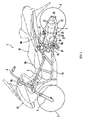
- FIG. 1 is a side view of the two wheeled motorized vehicle 1.
- the two wheeled motorized vehicle 1 includes a vehicle body frame 9, an engine unit 2 as a driving source unit, a rear wheel 3, and a front wheel 6.
- the vehicle body frame 9 includes a head pipe 9a disposed at the front end of the vehicle body, an upper tube 9b, a down tube 9c, a seat rail 9d, and a vertical frame member 9e.
- Steering handlebars 4 are attached to the upper end of the head pipe 9a and a front fork 5 is connected to the lower end of the head pipe 9a.
- a front wheel 6 is rotatably attached to the distal end of the front fork 5.
- the front wheel 6 is not connected to the engine unit 2. In other words, the front wheel 6 is a driven wheel.
- the down tube 9c extends obliquely rearward and downward from the head pipe 9a.
- the down tube 9c is bent at its intermediate portion to extend rearward and generally horizontally therefrom.
- the upper tube 9b extends obliquely rearward and downward above the down tube 9c from the connection between the head pipe 9a and the down tube 9c.
- the seat rail 9d is connected to the generally horizontal portion of the down tube 9c.
- the seat rail 9d extends obliquely rearward and upward from the connection with the down tube 9c.
- the lower end of the upper tube 9d is connected to the seat rail 9d.
- An intermediate portion of the seat rail 9d and the rear end of the down tube 9c is coupled via the vertical frame member 9e.
- a vehicle body cover or fairing 15 is provided to cover the vehicle body frame 9.
- a seat 16 for the rider to ride on is attached to the vehicle body cover 15.
- the engine unit 2 is directly attached to the vehicle body frame 9 so as to be pivotable.
- a pivot member 9f is attached to the vertical frame member 9e of the vehicle body frame 9.
- the pivot member 9f is formed in the shape of a cylinder extending in the vehicle width direction.
- a pivot shaft 9g extending in the vehicle width direction is attached to the pivot member 9f.
- a pivot part 2b is formed at a front and lower portion of a housing 2a of the engine unit 2.
- the pivot part 2b is formed with a through hole 2b1 having generally the same inner diameter as that of the pivot member 9f.
- the pivot shaft 9g is rotatably inserted into the through hole 2b1.
- the engine unit 2 is connected to an intermediate portion of the seat rail 9d via a rear cushion or suspension unit 17.
- the rear cushion unit 17 suppresses oscillations of the engine unit 2.
- the engine unit 2 includes an engine 10 and a transmission 20.
- the engine 10 is a 4-cycle forced-air-cooled engine.
- the engine 10 may be another type of engine.
- the engine 10 may be, for example, a water-cooled engine.
- the engine 10 may be a 2-cycle engine.
- a driving source other than engines such as an electric motor may be provided in place of the engine 10. In other words, the driving source of the present invention is not limited to specific types.
- the engine 10 includes a crankshaft 11 coupled to a piston 19.
- the transmission 20 is made up of a gear ratio change mechanism 20a, an ECU 7 as a control section, and a driving circuit 8 as a motor driving section.
- the gear ratio change mechanism 20a is a belt type ECVT.
- the gear ratio change mechanism 20a is not limited to a belt type ECVT.
- the gear ratio change mechanism 20a may be, for example, a toroidal type ECVT.
- the gear ratio change mechanism 20a includes a primary sheave 21, a secondary sheave 22, and a V-belt 23.
- the V-belt 23 is wound around the primary sheave 21 and the secondary sheave 22.
- the V-belt 23 has a generally V-shaped cross section.
- the primary sheave 21 rotates together with the crankshaft 11 as an input shaft.
- the primary sheave 21 includes a fixed sheave half 21a and a movable sheave half 21b.
- the fixed sheave half 21a is fixed to one end of the crankshaft 11.
- the movable sheave half 21b is disposed to oppose the fixed sheave half 21a so as to be displaceable in the axial direction of the crankshaft 11.
- the movable sheave half 21b is movable in the axial direction of the crankshaft 11.
- Respective opposing surfaces of the fixed sheave half 21a and the movable sheave half 21b form a belt groove 21c for receiving the V-belt 23.
- the belt groove 21c is wider toward the radially outer side of the primary sheave 21.
- the width of the belt groove 21c of the primary sheave 21 is changed as a motor 30 drives the movable sheave half 21b in the axial direction of the crankshaft 11.
- the motor 30 is driven by pulse width modulation (PWM).
- the secondary sheave 22 is disposed rearward of the primary sheave 21.
- the secondary sheave 22 is attached to a driven shaft 27 via a centrifugal clutch 25.
- the secondary sheave 22 includes a fixed sheave half 22a, which is provided with a cylindrical output shaft 22a1 that is formed integrally therewith, and a movable sheave half 22b.
- the movable sheave half 22b opposes the fixed sheave half 22a.
- the fixed sheave half 22a is coupled to the driven shaft 27 via the centrifugal clutch 25.
- the movable sheave half 22b is movable in the axial direction of the driven shaft 27.
- Respective opposing surfaces of the fixed sheave half 22a and the movable sheave half 22b form a belt groove 22c for receiving the V-belt 23.
- the belt groove 22c is wider toward the radially outer side of the secondary sheave 22.
- the movable sheave half 22b is urged by a spring 26 in the direction of reducing the width of the belt groove 22c.
- the motor 30 is driven to reduce the width of the belt groove 21c of the primary sheave 21 and thus increase the winding diameter of the V-belt 23 around the primary sheave 21, the V-belt 23 is pulled toward the radially inner side of the secondary sheave 22.
- This causes the movable sheave half 22b to move in the direction of increasing the width of the belt groove 22c against the urging force of the spring 26.
- This reduces the winding diameter of the V-belt 23 around the secondary sheave 22.
- the gear ratio of the gear ratio change mechanism 20a is changed.
- the centrifugal clutch 25 is engaged and disengaged according to the rotational speed of the fixed sheave half 22a. Specifically, when the rotational speed of the fixed sheave half 22a is less than a predetermined rotational speed, the centrifugal clutch 25 is not engaged. Therefore, the rotation of the fixed sheave half 22a is not transmitted to the driven shaft 27. On the other hand, when the rotational speed of the fixed sheave half 22a is equal to or more than the predetermined rotational speed, the centrifugal clutch 25 is engaged. Therefore, the rotation of the fixed sheave half 22a is transmitted to the driven shaft 27.
- a speed reduction mechanism 28 is coupled to the driven shaft 27.
- the driven shaft 27 is coupled to an axle 29 via the speed reduction mechanism 28.
- the rear wheel 3 is attached to the axle 29 for rotation. Therefore, as the driven shaft 27 rotates, the axle 29 and the rear wheel 3 rotate together.
- a sheave position sensor 40 is connected to the ECU 7.
- the sheave position sensor 40 detects the position of the movable sheave half 21b of the primary sheave 21 relative to the fixed sheave half 21a (hereinafter referred to as "sheave position " ).
- the sheave position sensor 40 detects the distance (1) between the fixed sheave half 21a and the movable sheave half 21b in the axial direction of the crankshaft 11.
- the sheave position sensor 40 outputs to the ECU 7 the detected distance (1) as a sheave position detection signal.
- the sheave position sensor 40 may be, for example, a potentiometer or the like.
- the primary sheave rotational speed sensor 43 detects the rotational speed of the primary sheave 21.
- the primary sheave rotational speed sensor 43 outputs to the ECU 7 the detected rotational speed of the primary sheave 21 as a sheave rotational speed signal.
- the secondary sheave rotational speed sensor 41 detects the rotational speed of the secondary sheave 22.
- the secondary sheave rotational speed sensor 41 outputs to the ECU 7 the detected rotational speed of the secondary sheave 22 as a sheave rotational speed signal.
- the vehicle speed sensor 42 detects the rotational speed of the rear wheel 3.
- the vehicle speed sensor 42 outputs to the ECU 7 a vehicle speed signal based on the detected rotational speed.
- a throttle opening sensor 18a outputs a throttle opening signal to the ECU 7 in the same way as described above.
- the ECU 7 performs feedback control of the position of the movable sheave half 21b of the primary sheave 21 based on the vehicle speed signal and so forth. In other words, the ECU 7 performs feedback control of the distance (1) based on the vehicle speed signal and so forth.
- the ECU 7 determines a target gear ratio based on the throttle opening and the vehicle speed. The ECU 7 then calculates a sheave target position based on the determined target gear ratio. In other words, the ECU 7 calculates a target distance (1) between the movable sheave half 21b and the fixed sheave half 21a based on the determined target gear ratio.
- the ECU 7 In order to displace the movable sheave half 21b to the sheave target position, the ECU 7 always applies a low-pass filtering process to a pulse width modulation (PWM) signal in accordance with the current position of the movable sheave half 21b and the sheave target position, before outputting the signal to the driving circuit 8.
- PWM pulse width modulation
- the driving circuit 8 applies to the motor 30 a pulse voltage in accordance with the pulse width modulation signal. This drives the movable sheave half 21b to adjust the gear ratio.
- “Applying a low-pass filtering process to a PWM signal” means gradually changing the PWM signal. That is, “applying a low-pass filtering process to a PWM signal” means moderating changes in the PWM signal. This allows the duty ratio of the pulse voltage to be applied to the motor 30 to change gradually rather than abruptly.
- the duty ratio will change abruptly from the current value D 1 to D 2 as shown in FIG. 6(a) , for example.
- the duty ratio will change abruptly as shown in FIG. 7 , for example, from 20% in FIG. 7(a) to 80% in FIG. 7(b) .
- the low-pass filtering process processes the PWM signal into a signal with a duty ratio that changes moderately from D 1 to D 2 . Therefore, in the case where the PWM signal after the low-pass filtering process is output to the driving circuit 8, the duty ratio changes moderately from D 1 to D 2 as shown in FIG. 6(b) .
- the duty ratio will change moderately as shown in FIG. 8 , for example, from 20% in FIG. 8(a) to 40% in FIG. 8(b) , then to 60% in FIG. 8(c) , and finally to 80% in FIG. 8(d) . Therefore, the magnitude of the effective voltage to be applied to the motor 30 also changes moderately.
- a control signal (specifically, a PWM signal) after being subjected to a low-pass filtering process in the ECU 7 is output to the driving circuit 8 as the motor driving section. Then, a pulse voltage in accordance with the low-pass filtered control signal is applied to the motor 30.
- the duty ratio of the pulse voltage to be applied to the motor 30 changes moderately as shown in FIG. 6(b ).
- the effective voltage to be applied to the motor 30 changes moderately.
- the torque of the motor 30 changes moderately rather than abruptly.
- gear ratio change shocks that occur in the two wheeled motorized vehicle 1 at gear ratio changes achieved by the motor 30 can be suppressed. This results in improved drivability of the two wheeled motorized vehicle 1.
- the PWM signal to be output to the driving circuit 8 is preferably always low-pass filtered.
- the cutoff frequency can be set as appropriate according to the type of the vehicle.
- the vehicle body frame 9 does not receive very large gear ratio change shocks even at abrupt changes in the gear ratio. Therefore, there is no significant demand to suppress abrupt changes in the effective voltage to be applied to the motor 30.
- the cutoff frequency of the low-pass filtering process is relatively low.
- suppressing abrupt changes in the effective voltage to be applied to the motor 30 by applying the low-pass filtering process to the PWM signal can reduce the inrush current into the motor 30.
- the number of times the motor 30 is driven in reverse for changing the gear ratio and the number of times when the motor 30 is activated are very large compared to motors for normal use. Therefore, there frequently occurs an inrush current at the activation and the reverse driving of the motor 30. As a result, a large burden is placed on the motor 30 and the driving circuit 8 therefor, reducing the durability of the motor 30 and the driving circuit 8.
- the duty ratio of the pulse voltage to be applied to the motor 30 changes abruptly as indicated by the dotted line in FIG. 9 , for example.
- the effective voltage to be applied to the motor 30 also changes abruptly. Therefore, a large inrush current is generated when the duty ratio of the pulse voltage to be applied to the motor 30 changes abruptly as indicated by the dotted line of FIG. 9(a) .
- a large inrush current occurs when the position of the movable sheave half 21b changes as shown in FIG. 10(b) , placing a load on the motor 30 and the driving circuit 8.
- the motor 30 is controlled by PWM. Therefore, power loss can be reduced when the motor 30 is driven, and a high energy efficiency can be achieved, with a simple circuitry.
- the duty ratio of the pulse voltage to be applied to the motor 30 is changed according to the control signal.
- the pulse height of the pulse voltage to be applied to the motor 30 (applied voltage) may be changed according to the control signal.
- the motor 30 may be controlled by PAM (pulse amplitude modulation).
- PAM pulse amplitude modulation
- a PAM signal for changing the pulse height of the pulse voltage to be applied to the motor 30 is output as a control signal from the ECU 7 to the driving circuit 8 after being subjected to a low-pass filtering process. Therefore, the pulse height of the pulse voltage to be applied to the motor 30 (applied voltage) changes moderately as shown in FIGs. 12 and 13 .
- the effective voltage to be applied to the motor 30 also changes moderately with gear ratio change shocks suppressed.
- the vehicle of the present invention is not limited as such.
- the vehicle of the present invention may be, for example, a non-scooter type two wheeled motorized vehicle.
- the vehicle of the present invention may be an off-road type, motorcycle type, scooter type, or so-called moped type two wheeled motorized vehicle.
- the vehicle of the present invention may be a straddle type vehicle other than the two wheeled motorized vehicle.
- the vehicle of the present invention may be, for example, an ATV (All Terrain Vehicle) or the like.
- the vehicle of the present invention may be a vehicle other than the straddle type vehicle such as a four-wheeled vehicle.
- the present invention is especially effective for two wheeled motorized vehicles.
- gear ratio change shocks are not easily transmitted to the rider and therefore are not a relatively significant problem.
- gear ratio change shocks are easily transmitted to the rider.
- gear ratio change shocks are a relatively significant problem.
- the gear ratio change mechanism 20a is not limited to a belt type ECVT.
- the gear ratio change mechanism 20a may be, for example, a toroidal type ECVT.
- the low-pass filtering process is applied to the control signal by software processing in the ECU 7.
- the low-pass filtering process may be applied to the control signal by a low-pass filtering circuit for performing a low-pass filtering process disposed between the ECU 7 and the driving circuit 8.
- the cutoff frequency can be set as appropriate according to the type of the vehicle.
- the low-pass filtering process is always applied to the control signal.
- the present invention is not limited to such a configuration.
- settings may be made to perform the low-pass filtering process on the control signal only when the gear ratio is changed relatively significantly.
- the rider may be allowed to select between an ON mode where the low-pass filtering process is applied to the control signal and an OFF mode where the low-pass filtering process is not applied to the control signal.
- a selection switch for allowing selection between the ON mode and the OFF mode may be disposed in the vehicle in order to apply the low-pass filtering process to the control signal only when the ON mode is selected by the rider.
- driving source refers to a device that generates power.
- the “driving source” may be, for example, an internal combustion engine, an electric motor or the like.
- pulse height of pulse voltage refers to the magnitude of the pulse voltage to be actually applied to the motor 30. That is, the term “effective voltage” refers to a value obtained by multiplying the magnitude of the pulse voltage by the duty ratio.
- the present invention is effectively applicable to ECVTs.
Landscapes
- Engineering & Computer Science (AREA)
- General Engineering & Computer Science (AREA)
- Mechanical Engineering (AREA)
- Control Of Transmission Device (AREA)
- Electric Propulsion And Braking For Vehicles (AREA)
- Gear-Shifting Mechanisms (AREA)
Abstract
Description
- The present invention relates to a transmission, a vehicle having the transmission, and a control device and a control method for the transmission.
- Electronically controlled continuously variable transmissions (hereinafter referred to as "ECVTs") are known, for examplefrom
JP-A-2004-19740 - An ECVT includes an input shaft, an output shaft, and a gear ratio change motor for changing the gear ratio between the input shaft and the output shaft. In general, the gear ratio change motor is driven by applying a pulse voltage with a view to reducing power loss.
- Vehicles having the conventional ECVT, however, may generate gear ratio change shocks at gear ratio changes and thus provide poor drivability.
- For example, in the case where a driving source unit including the ECVT is directly attached to a vehicle body frame so as to be pivotable, such gear ratio change shocks are transmitted to the rider particularly easily, which may further deteriorate the drivability.
- The present invention has been made in view of the foregoing problem, and therefore has an object to improve the drivability of a vehicle having an ECVT by suppressing gear ratio change shocks.
- A transmission in accordance with the present invention includes a gear ratio change mechanism, a motor driving section, and a control section. The gear ratio change mechanism has an input shaft, an output shaft, and a motor. The motor continuously varies the gear ratio between the input shaft and the output shaft. The motor driving section applies a pulse voltage to the motor. The control section outputs a control signal to the motor driving section. At least one of the duty ratio and the pulse height of the pulse voltage is changed according to the control signal. The control section outputs to the motor driving section a low-pass filtered control signal after applying a low-pass filtering process to the control signal.
- A vehicle in accordance with the present invention includes the gear ratio change mechanism in accordance with the present invention.
- A control device in accordance with the present invention controls a gear ratio change mechanism having an input shaft, an output shaft, and a motor for continuously varying the gear ratio between the input shaft and the output shaft. The control device in accordance with the present invention includes a motor driving section and a control section. The motor driving section applies a pulse voltage to the motor. The control section outputs a control signal to the motor driving section. At least one of the duty ratio and the pulse height of the pulse voltage is changed according to the control signal. The control section outputs to the motor driving section a low-pass filtered control signal after applying a low-pass filtering process to the control signal.
- A control method in accordance with the present invention controls a gear ratio change mechanism having an input shaft, an output shaft, and a motor for continuously varying the gear ratio between the input shaft and the output shaft. The control method in accordance with the present invention includes: applying a low-pass filtering process to a control signal for changing at least one of the duty ratio and the pulse height of a pulse voltage; and applying to the motor the pulse voltage controlled by a low-pass filtered control signal to drive the motor.
- Aspects of the present invention are set forth in the independent claims.
- Preferred features of the present invention are set forth in the dependent claims
- The present invention can improve the drivability by suppressing gear ratio change shocks.
- These and otyher aspects of the present invention will now be described, by way of example only, with reference to the accompanying drawings, in which:
-
FIG. 1 is a side view of a two wheeled motorized vehicle to which the present invention may be applied; -
FIG. 2 is a partial cross sectional view of an engine unit as viewed from a side thereof; -
FIG. 3 is a partial cross sectional view of the engine unit; -
FIG. 4 is a block diagram illustrating a control system of the two wheeled motorized vehicle; -
FIG. 5 is a block diagram illustrating sheave position control; -
FIG. 6 is a schematic diagram for illustrating changes in the duty ratio of a pulse voltage to be applied to a motor, specifically in which:-
FIG. 6(a) is a graph representing changes in the duty ratio of the pulse voltage to be applied to the motor without a low-pass filtering process applied to a PWM signal; and -
FIG. 6(b) is a graph representing changes in the duty ratio of the pulse voltage to be applied to the motor with a low-pass filtering process applied to the PWM signal;
-
-
FIG. 7 is a schematic diagram illustrating changes in the waveform of the pulse voltage in the case where the PWM signal before the low-pass filtering process is directly output to a driving circuit; -
FIG. 8 is a schematic diagram showing changes in the waveform of the pulse voltage in the case where the PWM signal after the low-pass filtering process is output to the driving circuit; -
FIG. 9 is a schematic diagram illustrating the relationship between the duty ratio of the pulse voltage to be applied to the motor and the current that passes through the motor; -
FIG. 10 is a graph showing the current that passes through the motor in the case where the low-pass filtering process is not applied to the PWM signal, specifically in which:-
FIG. 10(a) is a graph representing the position of a movable sheave half of a primary sheave; -
FIG. 10(b) is a graph representing the current that passes through the motor; and -
FIG. 10(c) is a graph representing the duty ratio of the pulse voltage to be applied to the motor;
-
-
FIG. 11 is a graph showing the current that passes through the motor in the case where the low-pass filtering process is applied to the PWM signal, specifically in which:-
FIG. 11(a) is a graph representing the position of the movable sheave half of the primary sheave; -
FIG. 11(b) is a graph representing the current that passes through themotor 30; and -
FIG. 10(c) is a graph representing the duty ratio of the pulse voltage to be applied to the motor;
-
-
FIG. 12 is a schematic diagram for explaining changes in the pulse height of the pulse voltage to be applied to the motor (applied voltage), specifically in which:-
FIG. 12(a) is a graph representing changes in the pulse height of the pulse voltage (applied voltage) to be applied to the motor without the low-pass filtering process applied to the PWM signal; and -
FIG. 12(b) is a graph representing changes in the pulse height of the pulse voltage (applied voltage) to be applied to the motor with the low-pass filtering process applied to the PWM signal; and
-
-
FIG. 13 is a schematic diagram showing changes in the waveform of the pulse voltage in the case where a PAM signal after the low-pass filtering process is output to the driving circuit. - A detailed description will hereinafter be made of a preferred embodiment of the present invention used within a two wheeled motorized vehicle 1 shown in
FIG. 1 as an example. A so-called scooter type is provided as an example of a vehicle in the description of this embodiment. However, the vehicle of the present invention is not limited to the scooter type two wheeled motorized vehicle. The vehicle of the present invention may be, for example, a non-scooter type two wheeled motorized vehicle. Specifically, the vehicle of the present invention may be an off-road type, motorcycle type, scooter type, or so-called moped type two wheeled motorized vehicle. In addition, the vehicle of the present invention may be a straddle type vehicle other than the two wheeled motorized vehicle. Specifically, the vehicle of the present invention may be, for example, an ATV (All Terrain Vehicle) or the like. Further, the vehicle of the present invention may be a vehicle other than the straddle type vehicle such as a four-wheeled vehicle. -
FIG. 1 is a side view of the two wheeled motorized vehicle 1. The two wheeled motorized vehicle 1 includes avehicle body frame 9, anengine unit 2 as a driving source unit, a rear wheel 3, and a front wheel 6. - The
vehicle body frame 9 includes ahead pipe 9a disposed at the front end of the vehicle body, anupper tube 9b, adown tube 9c, aseat rail 9d, and avertical frame member 9e. Steering handlebars 4 are attached to the upper end of thehead pipe 9a and afront fork 5 is connected to the lower end of thehead pipe 9a. A front wheel 6 is rotatably attached to the distal end of thefront fork 5. The front wheel 6 is not connected to theengine unit 2. In other words, the front wheel 6 is a driven wheel. - The down
tube 9c extends obliquely rearward and downward from thehead pipe 9a. The downtube 9c is bent at its intermediate portion to extend rearward and generally horizontally therefrom. Theupper tube 9b extends obliquely rearward and downward above thedown tube 9c from the connection between thehead pipe 9a and thedown tube 9c. Theseat rail 9d is connected to the generally horizontal portion of thedown tube 9c. Theseat rail 9d extends obliquely rearward and upward from the connection with thedown tube 9c. The lower end of theupper tube 9d is connected to theseat rail 9d. An intermediate portion of theseat rail 9d and the rear end of thedown tube 9c is coupled via thevertical frame member 9e. - A vehicle body cover or fairing 15 is provided to cover the
vehicle body frame 9. Aseat 16 for the rider to ride on is attached to thevehicle body cover 15. - The
engine unit 2 is directly attached to thevehicle body frame 9 so as to be pivotable. Specifically, as shown inFIG. 1 , apivot member 9f is attached to thevertical frame member 9e of thevehicle body frame 9. Thepivot member 9f is formed in the shape of a cylinder extending in the vehicle width direction. A pivot shaft 9g extending in the vehicle width direction is attached to thepivot member 9f. On the other hand, as shown inFIG. 2 , apivot part 2b is formed at a front and lower portion of ahousing 2a of theengine unit 2. Thepivot part 2b is formed with a through hole 2b1 having generally the same inner diameter as that of thepivot member 9f. The pivot shaft 9g is rotatably inserted into the through hole 2b1. - As shown in
FIG. 1 , theengine unit 2 is connected to an intermediate portion of theseat rail 9d via a rear cushion orsuspension unit 17. Therear cushion unit 17 suppresses oscillations of theengine unit 2. - A description will now be made of the construction of the
engine unit 2 with reference toFIG. 3 . - As shown in
FIG. 3 , theengine unit 2 includes anengine 10 and atransmission 20. In the description of this embodiment, theengine 10 is a 4-cycle forced-air-cooled engine. However, theengine 10 may be another type of engine. Theengine 10 may be, for example, a water-cooled engine. Theengine 10 may be a 2-cycle engine. A driving source other than engines such as an electric motor may be provided in place of theengine 10. In other words, the driving source of the present invention is not limited to specific types. As shown inFIG. 3 , theengine 10 includes a crankshaft 11 coupled to apiston 19. - The
transmission 20 is made up of a gearratio change mechanism 20a, anECU 7 as a control section, and adriving circuit 8 as a motor driving section. In the description of this embodiment, the gearratio change mechanism 20a is a belt type ECVT. However, the gearratio change mechanism 20a is not limited to a belt type ECVT. The gearratio change mechanism 20a may be, for example, a toroidal type ECVT. - The gear
ratio change mechanism 20a includes aprimary sheave 21, asecondary sheave 22, and a V-belt 23. The V-belt 23 is wound around theprimary sheave 21 and thesecondary sheave 22. The V-belt 23 has a generally V-shaped cross section. - The
primary sheave 21 rotates together with the crankshaft 11 as an input shaft. Theprimary sheave 21 includes a fixed sheave half 21a and amovable sheave half 21b. The fixed sheave half 21a is fixed to one end of the crankshaft 11. Themovable sheave half 21b is disposed to oppose the fixed sheave half 21a so as to be displaceable in the axial direction of the crankshaft 11. Themovable sheave half 21b is movable in the axial direction of the crankshaft 11. Respective opposing surfaces of the fixed sheave half 21a and themovable sheave half 21b form abelt groove 21c for receiving the V-belt 23. Thebelt groove 21c is wider toward the radially outer side of theprimary sheave 21. - The width of the
belt groove 21c of theprimary sheave 21 is changed as amotor 30 drives themovable sheave half 21b in the axial direction of the crankshaft 11. In the description of this embodiment, themotor 30 is driven by pulse width modulation (PWM). - The
secondary sheave 22 is disposed rearward of theprimary sheave 21. Thesecondary sheave 22 is attached to a drivenshaft 27 via acentrifugal clutch 25. Specifically, thesecondary sheave 22 includes a fixedsheave half 22a, which is provided with a cylindrical output shaft 22a1 that is formed integrally therewith, and amovable sheave half 22b. Themovable sheave half 22b opposes the fixedsheave half 22a. The fixedsheave half 22a is coupled to the drivenshaft 27 via thecentrifugal clutch 25. Themovable sheave half 22b is movable in the axial direction of the drivenshaft 27. Respective opposing surfaces of the fixedsheave half 22a and themovable sheave half 22b form abelt groove 22c for receiving the V-belt 23. Thebelt groove 22c is wider toward the radially outer side of thesecondary sheave 22. - The
movable sheave half 22b is urged by aspring 26 in the direction of reducing the width of thebelt groove 22c. When themotor 30 is driven to reduce the width of thebelt groove 21c of theprimary sheave 21 and thus increase the winding diameter of the V-belt 23 around theprimary sheave 21, the V-belt 23 is pulled toward the radially inner side of thesecondary sheave 22. This causes themovable sheave half 22b to move in the direction of increasing the width of thebelt groove 22c against the urging force of thespring 26. This in turn reduces the winding diameter of the V-belt 23 around thesecondary sheave 22. As a result, the gear ratio of the gearratio change mechanism 20a is changed. - The centrifugal clutch 25 is engaged and disengaged according to the rotational speed of the fixed
sheave half 22a. Specifically, when the rotational speed of the fixedsheave half 22a is less than a predetermined rotational speed, the centrifugal clutch 25 is not engaged. Therefore, the rotation of the fixedsheave half 22a is not transmitted to the drivenshaft 27. On the other hand, when the rotational speed of the fixedsheave half 22a is equal to or more than the predetermined rotational speed, the centrifugal clutch 25 is engaged. Therefore, the rotation of the fixedsheave half 22a is transmitted to the drivenshaft 27. - A
speed reduction mechanism 28 is coupled to the drivenshaft 27. The drivenshaft 27 is coupled to anaxle 29 via thespeed reduction mechanism 28. As shown inFIG. 1 , the rear wheel 3 is attached to theaxle 29 for rotation. Therefore, as the drivenshaft 27 rotates, theaxle 29 and the rear wheel 3 rotate together. - A detailed description will now be made of a control system of the two wheeled motorized vehicle 1 with reference to
FIG. 4 . - As shown in
FIG. 4 , asheave position sensor 40 is connected to theECU 7. Thesheave position sensor 40 detects the position of themovable sheave half 21b of theprimary sheave 21 relative to the fixed sheave half 21a (hereinafter referred to as "sheave position"). In other words, thesheave position sensor 40 detects the distance (1) between the fixed sheave half 21a and themovable sheave half 21b in the axial direction of the crankshaft 11. Thesheave position sensor 40 outputs to theECU 7 the detected distance (1) as a sheave position detection signal. Thesheave position sensor 40 may be, for example, a potentiometer or the like. - To the
ECU 7 are connected a primary sheave rotational speed sensor 43, a secondary sheaverotational speed sensor 41, and avehicle speed sensor 42. The primary sheave rotational speed sensor 43 detects the rotational speed of theprimary sheave 21. The primary sheave rotational speed sensor 43 outputs to theECU 7 the detected rotational speed of theprimary sheave 21 as a sheave rotational speed signal. The secondary sheaverotational speed sensor 41 detects the rotational speed of thesecondary sheave 22. The secondary sheaverotational speed sensor 41 outputs to theECU 7 the detected rotational speed of thesecondary sheave 22 as a sheave rotational speed signal. Thevehicle speed sensor 42 detects the rotational speed of the rear wheel 3. Thevehicle speed sensor 42 outputs to the ECU 7 a vehicle speed signal based on the detected rotational speed. - A steering switch attached at the steering handlebars 4 shown in
FIG. 1 is connected to theECU 7. As shown inFIG. 4 , the steering switch outputs a steering SW signal when the steering switch is operated by the rider. - A
throttle opening sensor 18a outputs a throttle opening signal to theECU 7 in the same way as described above. - The
ECU 7 performs feedback control of the position of themovable sheave half 21b of theprimary sheave 21 based on the vehicle speed signal and so forth. In other words, theECU 7 performs feedback control of the distance (1) based on the vehicle speed signal and so forth. - Specifically, as shown in
FIG. 5 , theECU 7 determines a target gear ratio based on the throttle opening and the vehicle speed. TheECU 7 then calculates a sheave target position based on the determined target gear ratio. In other words, theECU 7 calculates a target distance (1) between themovable sheave half 21b and the fixed sheave half 21a based on the determined target gear ratio. In order to displace themovable sheave half 21b to the sheave target position, theECU 7 always applies a low-pass filtering process to a pulse width modulation (PWM) signal in accordance with the current position of themovable sheave half 21b and the sheave target position, before outputting the signal to thedriving circuit 8. As shown inFIG. 4 , the drivingcircuit 8 applies to the motor 30 a pulse voltage in accordance with the pulse width modulation signal. This drives themovable sheave half 21b to adjust the gear ratio. - "Applying a low-pass filtering process to a PWM signal" means gradually changing the PWM signal. That is, "applying a low-pass filtering process to a PWM signal" means moderating changes in the PWM signal. This allows the duty ratio of the pulse voltage to be applied to the
motor 30 to change gradually rather than abruptly. - Specifically, in the case where the PWM signal before the low-pass filtering process is directly output to the
driving circuit 8, the duty ratio will change abruptly from the current value D1 to D2 as shown inFIG. 6(a) , for example. The duty ratio will change abruptly as shown inFIG. 7 , for example, from 20% inFIG. 7(a) to 80% inFIG. 7(b) . - In contrast, the low-pass filtering process processes the PWM signal into a signal with a duty ratio that changes moderately from D1 to D2. Therefore, in the case where the PWM signal after the low-pass filtering process is output to the
driving circuit 8, the duty ratio changes moderately from D1 to D2 as shown inFIG. 6(b) . The duty ratio will change moderately as shown inFIG. 8 , for example, from 20% inFIG. 8(a) to 40% inFIG. 8(b) , then to 60% inFIG. 8(c) , and finally to 80% inFIG. 8(d) . Therefore, the magnitude of the effective voltage to be applied to themotor 30 also changes moderately. - In this embodiment, as has been described above, a control signal (specifically, a PWM signal) after being subjected to a low-pass filtering process in the
ECU 7 is output to thedriving circuit 8 as the motor driving section. Then, a pulse voltage in accordance with the low-pass filtered control signal is applied to themotor 30. Thus, the duty ratio of the pulse voltage to be applied to themotor 30 changes moderately as shown inFIG. 6(b ). As a result, the effective voltage to be applied to themotor 30 changes moderately. Hence, the torque of themotor 30 changes moderately rather than abruptly. Thus, gear ratio change shocks that occur in the two wheeled motorized vehicle 1 at gear ratio changes achieved by themotor 30 can be suppressed. This results in improved drivability of the two wheeled motorized vehicle 1. From the viewpoint of suppressing gear ratio change shocks in the two wheeled motorized vehicle 1, the PWM signal to be output to thedriving circuit 8 is preferably always low-pass filtered. - From the viewpoint of further suppressing gear ratio change shocks that occur in the two wheeled motorized vehicle 1, changes in the effective voltage to be applied to the
motor 30 are preferably made more moderate. Therefore, from the viewpoint of further suppressing gear ratio change shocks that occur in the two wheeled motorized vehicle 1, it is preferable that the cutoff frequency of the low-pass filtering process to be performed on the PWM signal is relatively low. A relatively low cutoff frequency of the low-pass filtering process, however, accordingly reduces the tracking speed of themotor 30 at the time when the target gear ratio is changed. As a result, the swiftness of the operation of the two wheeled motorized vehicle is reduced. Therefore, it is preferable that the cutoff frequency for a two wheeled motorized vehicle that requires swift operation is relatively high. In other words, it is preferable to set a relatively low cutoff frequency for types of two wheeled motorized vehicles that do not require very swift operation but require that gear ratio change shocks in the vehicle be particularly small. On the other hand, it is preferable to set a relatively high cutoff frequency for types of vehicles that require swift operation rather than suppression of gear ratio change shocks. That is, the cutoff frequency can be set as appropriate according to the type of the vehicle. - For example, in a two wheeled motorized vehicle in which the
engine unit 2 and thevehicle body frame 9 are coupled to each other via one or a plurality of link mechanisms that are pivotable relative to thevehicle body frame 9, and in which fluctuations in the torque generated at the rear wheel 3 are thus not directly transmitted to thevehicle body frame 9, thevehicle body frame 9 does not receive very large gear ratio change shocks even at abrupt changes in the gear ratio. Therefore, there is no significant demand to suppress abrupt changes in the effective voltage to be applied to themotor 30. - In contrast, in the two wheeled motorized vehicle 1 of this embodiment in which the
engine unit 2 as the driving source unit is directly attached to thevehicle body frame 9 so as to be pivotable, vibrations and oscillations in the front-and-rear direction applied to theengine unit 2 are directly transmitted to thevehicle body frame 9. Hence, fluctuations in the torque generated at the rear wheel 3 are easily transmitted to thevehicle body frame 9. This permits gear ratio change shocks to be easily transmitted to thevehicle body frame 9 while allowing swift operation. Therefore, there is strong demand to suppress abrupt changes in the effective voltage to be applied to themotor 30 for the two wheeled motorized vehicle 1 of this embodiment in which theengine unit 2 as the driving source unit is directly attached to thevehicle body frame 9 so as to be pivotable. Thus, it is particularly effective to suppress abrupt changes in the effective voltage to be applied to themotor 30 as in this embodiment. In addition, in the two wheeled motorized vehicle 1 of this embodiment, it is preferable that the cutoff frequency of the low-pass filtering process is relatively low. - In addition, suppressing abrupt changes in the effective voltage to be applied to the
motor 30 by applying the low-pass filtering process to the PWM signal can reduce the inrush current into themotor 30. - The number of times the
motor 30 is driven in reverse for changing the gear ratio and the number of times when themotor 30 is activated are very large compared to motors for normal use. Therefore, there frequently occurs an inrush current at the activation and the reverse driving of themotor 30. As a result, a large burden is placed on themotor 30 and the drivingcircuit 8 therefor, reducing the durability of themotor 30 and the drivingcircuit 8. - In the case where the low-pass filtering process is not applied to the PWM signal, the duty ratio of the pulse voltage to be applied to the
motor 30 changes abruptly as indicated by the dotted line inFIG. 9 , for example. As a result, the effective voltage to be applied to themotor 30 also changes abruptly. Therefore, a large inrush current is generated when the duty ratio of the pulse voltage to be applied to themotor 30 changes abruptly as indicated by the dotted line ofFIG. 9(a) . Thus, a large inrush current occurs when the position of themovable sheave half 21b changes as shown inFIG. 10(b) , placing a load on themotor 30 and the drivingcircuit 8. - In contrast, applying the low-pass filtering process to the PWM signal suppresses abrupt changes in the effective voltage to be applied to the
motor 30 as indicated by the solid line inFIG. 9(b) . As a result, an increase in the current that flows into themotor 30 is suppressed as indicated by the solid line inFIG. 9(a) . In other words, an inrush current that flows into themotor 30 can be made smaller. Thus, an inrush current that occurs when the position of themovable sheave half 21b changes can be suppressed as shown inFIG. 11(b) , reducing the load on themotor 30 and the drivingcircuit 8. Hence, the service life of themotor 30 and the drivingcircuit 8 can be extended. - In this embodiment, the
motor 30 is controlled by PWM. Therefore, power loss can be reduced when themotor 30 is driven, and a high energy efficiency can be achieved, with a simple circuitry. - In the description of the above embodiment, the duty ratio of the pulse voltage to be applied to the
motor 30 is changed according to the control signal. However, the pulse height of the pulse voltage to be applied to the motor 30 (applied voltage) may be changed according to the control signal. In other words, themotor 30 may be controlled by PAM (pulse amplitude modulation). In this case, a PAM signal for changing the pulse height of the pulse voltage to be applied to themotor 30 is output as a control signal from theECU 7 to thedriving circuit 8 after being subjected to a low-pass filtering process. Therefore, the pulse height of the pulse voltage to be applied to the motor 30 (applied voltage) changes moderately as shown inFIGs. 12 and 13 . As a result, the effective voltage to be applied to themotor 30 also changes moderately with gear ratio change shocks suppressed. Hence, it is possible to improve the drivability and to make the inrush current that flows into themotor 30 and the drivingcircuit 8 smaller, as in the case of the above embodiment. - Although the two wheeled motorized vehicle 1 of the so-called scooter type is provided as an example in the description of the above embodiment, the vehicle of the present invention is not limited as such. The vehicle of the present invention may be, for example, a non-scooter type two wheeled motorized vehicle. Specifically, the vehicle of the present invention may be an off-road type, motorcycle type, scooter type, or so-called moped type two wheeled motorized vehicle. In addition, the vehicle of the present invention may be a straddle type vehicle other than the two wheeled motorized vehicle. Specifically, the vehicle of the present invention may be, for example, an ATV (All Terrain Vehicle) or the like. Further, the vehicle of the present invention may be a vehicle other than the straddle type vehicle such as a four-wheeled vehicle.
- It should be noted that the present invention is especially effective for two wheeled motorized vehicles. In relatively heavyweight types of vehicles such as four-wheeled vehicles, gear ratio change shocks are not easily transmitted to the rider and therefore are not a relatively significant problem. In contrast, in two wheeled motorized vehicles, which are relatively lightweight, gear ratio change shocks are easily transmitted to the rider. Hence, gear ratio change shocks are a relatively significant problem.
- The gear
ratio change mechanism 20a is not limited to a belt type ECVT. The gearratio change mechanism 20a may be, for example, a toroidal type ECVT. - In the description of the above embodiment, the low-pass filtering process is applied to the control signal by software processing in the
ECU 7. In the present invention, however, the low-pass filtering process may be applied to the control signal by a low-pass filtering circuit for performing a low-pass filtering process disposed between theECU 7 and the drivingcircuit 8. - It is preferable to set a relatively low cutoff frequency for types of two wheeled motorized vehicles that do not require very swift operation but require that gear ratio change shocks in the vehicle be particularly small. On the other hand, it is preferable to set a relatively high cutoff frequency for types of vehicles that require swift operation rather than suppression of gear ratio change shocks. That is, the cutoff frequency can be set as appropriate according to the type of the vehicle.
- In the description of the above embodiment, the low-pass filtering process is always applied to the control signal. However, the present invention is not limited to such a configuration. For example, settings may be made to perform the low-pass filtering process on the control signal only when the gear ratio is changed relatively significantly. Alternatively, the rider may be allowed to select between an ON mode where the low-pass filtering process is applied to the control signal and an OFF mode where the low-pass filtering process is not applied to the control signal. Specifically, a selection switch for allowing selection between the ON mode and the OFF mode may be disposed in the vehicle in order to apply the low-pass filtering process to the control signal only when the ON mode is selected by the rider.
- In the description of the above embodiment and Modification 1, only one of the duty ratio and the pulse height of the pulse voltage to be applied to the
motor 30 is changed according to the control signal. However, both the duty ratio and the pulse height of the pulse voltage to be applied to themotor 30 may be changed according to the control signal. - The term "driving source" refers to a device that generates power. The "driving source" may be, for example, an internal combustion engine, an electric motor or the like.
- The term "pulse height of pulse voltage" refers to the magnitude of the pulse voltage to be actually applied to the
motor 30. That is, the term "effective voltage" refers to a value obtained by multiplying the magnitude of the pulse voltage by the duty ratio. - The present invention is effectively applicable to ECVTs.
-
- 1: two wheeled motorized vehicle
- 2: engine unit (driving source unit)
- 3: rear wheel (driving wheel)
- 6: front wheel (driven wheel)
- 7: ECU (control section)
- 8: driving circuit (motor driving section)
- 9: vehicle body frame
- 10: engine
- 11: crankshaft (input shaft)
- 20: transmission
- 20a:gear ratio change mechanism
- 21: primary sheave
- 21a:fixed sheave half
- 21b:movable sheave half
- 22: secondary sheave
- 22a:fixed sheave half
- 22a1:output shaft
- 22b:movable sheave half
- 23: V-belt
- 25: centrifugal clutch
- 27: driven shaft
- 28: speed reduction mechanism
- 29: axle
- 30: motor
- 40: sheave position sensor
- 42: vehicle speed sensor
Claims (8)
- A transmission (20) comprising:a gear ratio change mechanism (20a) having an input shaft (11), an output shaft (22a1), and a motor (30) for continuously varying a gear ratio between the input shaft (11) and the output shaft (22a1);a motor driving section (8) for applying a pulse voltage to the motor (30); anda control section (7) for outputting to the motor driving section (8) a control signal for changing at least one of a duty ratio and a pulse height of the pulse voltage,wherein the control section (7) outputs to the motor driving section (8) a low-pass filtered control signal after applying a low-pass filtering process to the control signal.
- The transmission (20) according to claim 1,
wherein the control section (7) always applies a low-pass filtering process to the control signal. - The transmission (20) according to claim 1 or 2,
wherein the control signal is a pulse width modulation control signal for controlling the duty ratio of the pulse voltage. - A vehicle (1) comprising a transmission (20) according to claim 1, 2 or 3.
- The vehicle (1) according to claim 4, further comprising:a driving source connected to the input shaft (11) to form a driving source unit (2) in conjunction with the transmission (20); anda vehicle body frame (9),wherein the driving source unit (2) is directly attached to the vehicle body frame (9) so as to be pivotable.
- The vehicle (1) according to claim 4 or 5, privided in the form of a two wheeled motorized vehicle.
- A control device for a gear ratio change mechanism (20a) having an input shaft (11), an output shaft (22a1), and a motor (30) for continuously varying a gear ratio between the input shaft (11) and the output shaft (22a1), the control device comprising:a motor driving section (8) for applying a pulse voltage to the motor (30); anda control section (7) for outputting to the motor driving section (8) a control signal for changing at least one of a duty ratio and a pulse height of the pulse voltage,wherein the control section (7) outputs to the motor driving section (8) a low-pass filtered control signal after applying a low-pass filtering process to the control signal.
- A control method for a gear ratio change mechanism (20a) having an input shaft (11), an output shaft (22a1), and a motor (30) for continuously varying a gear ratio between the input shaft (11) and the output shaft (22a1), the control method comprising:applying a low-pass filtering process to a control signal for changing at least one of a duty ratio and a pulse height of a pulse voltage; andapplying to the motor (30) the pulse voltage controlled by a low-pass filtered control signal to drive the motor (30) .
Applications Claiming Priority (1)
| Application Number | Priority Date | Filing Date | Title |
|---|---|---|---|
| JP2007021241A JP2008185187A (en) | 2007-01-31 | 2007-01-31 | Transmission, vehicle equipped therewith, control device for transmission mechanism, and control method therefor |
Publications (3)
| Publication Number | Publication Date |
|---|---|
| EP1953428A2 true EP1953428A2 (en) | 2008-08-06 |
| EP1953428A3 EP1953428A3 (en) | 2011-03-30 |
| EP1953428B1 EP1953428B1 (en) | 2012-03-14 |
Family
ID=39304840
Family Applications (1)
| Application Number | Title | Priority Date | Filing Date |
|---|---|---|---|
| EP08250190A Active EP1953428B1 (en) | 2007-01-31 | 2008-01-15 | Transmission |
Country Status (7)
| Country | Link |
|---|---|
| US (1) | US8090509B2 (en) |
| EP (1) | EP1953428B1 (en) |
| JP (1) | JP2008185187A (en) |
| CN (1) | CN101235896B (en) |
| AT (1) | ATE549553T1 (en) |
| ES (1) | ES2382356T3 (en) |
| TW (1) | TWI375764B (en) |
Families Citing this family (10)
| Publication number | Priority date | Publication date | Assignee | Title |
|---|---|---|---|---|
| US9429235B2 (en) | 2011-10-14 | 2016-08-30 | Polaris Industries Inc. | Primary clutch electronic CVT |
| US8534413B2 (en) | 2011-10-14 | 2013-09-17 | Polaris Industries Inc. | Primary clutch electronic CVT |
| CN102750451B (en) * | 2012-07-02 | 2015-04-22 | 株洲南车时代电气股份有限公司 | Motor speed calculation device |
| US10648554B2 (en) | 2014-09-02 | 2020-05-12 | Polaris Industries Inc. | Continuously variable transmission |
| KR101725484B1 (en) * | 2016-03-07 | 2017-04-10 | 서강대학교산학협력단 | Driving Method Of Motor |
| EP3505797B1 (en) * | 2016-08-29 | 2020-06-17 | Nissan Motor Co., Ltd | Control method for continuously variable transmissions |
| CN111836980A (en) | 2018-03-19 | 2020-10-27 | 北极星工业有限公司 | CVT |
| CN110748638B (en) * | 2018-07-24 | 2021-09-10 | 郑州宇通客车股份有限公司 | PWM duty ratio control method, gear shifting method and gear shifting device of gear shifting motor |
| WO2022165160A1 (en) | 2021-01-29 | 2022-08-04 | Polaris Industries Inc. | Electronically-controlled continuously variable transmission for a utility vehicle |
| US12486896B2 (en) * | 2022-03-18 | 2025-12-02 | Jatco Ltd | Control device for transmission |
Citations (1)
| Publication number | Priority date | Publication date | Assignee | Title |
|---|---|---|---|---|
| JP2004019740A (en) | 2002-06-14 | 2004-01-22 | Mazda Motor Corp | Control device for continuously variable transmission |
Family Cites Families (35)
| Publication number | Priority date | Publication date | Assignee | Title |
|---|---|---|---|---|
| US3604288A (en) * | 1968-10-30 | 1971-09-14 | Nissan Motor | Electronic control system for automotive automatic transmission |
| DE2132397C2 (en) * | 1971-06-30 | 1982-07-01 | Daimler-Benz Ag, 7000 Stuttgart | "Device for controlling the working oil pressure for an automatically shiftable multi-step transmission" |
| US5252905A (en) * | 1985-12-23 | 1993-10-12 | York International Corporation | Driving system for single phase A-C induction motor |
| US5115395A (en) * | 1987-03-13 | 1992-05-19 | Borg-Warner Automotive, Inc. | Pulse width modulation technique |
| US5285389A (en) * | 1989-09-15 | 1994-02-08 | Borg-Warner Automotive Inc. | Dual microprocessor architecture for control of a continuously variable transmission |
| DE4328893B4 (en) * | 1992-08-27 | 2007-07-05 | Hitachi, Ltd. | Method and device for controlling an automatic transmission of a vehicle as a function of a gradient of a roadway |
| JP3375362B2 (en) * | 1993-02-24 | 2003-02-10 | 本田技研工業株式会社 | Continuously variable transmission control device for vehicles |
| JP3677145B2 (en) | 1996-11-30 | 2005-07-27 | 日本電産シンポ株式会社 | Rotation control device and rotation control method |
| AU9659898A (en) * | 1997-10-21 | 1999-05-10 | Stridsberg Innovation Ab | A hybrid powertrain |
| US6485057B1 (en) * | 1997-12-16 | 2002-11-26 | Nsk Autoliv Co., Ltd. | Automotive passenger restraint and protection apparatus and seatbelt protraction and retraction amount-detecting device |
| US6653829B1 (en) * | 1999-09-17 | 2003-11-25 | Delphi Technologies, Inc. | Low cost approach to measuring high resolution rotary position of electric machines |
| JP2002005277A (en) * | 2000-06-22 | 2002-01-09 | Denso Corp | Vehicle control system |
| JP2002213599A (en) * | 2001-01-19 | 2002-07-31 | Nissan Motor Co Ltd | Shift control device for continuously variable transmission for vehicle with vehicle speed control device |
| JP2002347479A (en) * | 2001-05-29 | 2002-12-04 | Denso Corp | Vehicle integrated control system |
| US6771919B2 (en) * | 2001-07-18 | 2004-08-03 | Ricoh Company, Ltd. | Image forming apparatus with reduced variation of rotation speed of image carrier |
| JP4206663B2 (en) * | 2001-12-17 | 2009-01-14 | アイシン精機株式会社 | Shift control device for automatic transmission |
| AU2002354225A1 (en) * | 2002-12-18 | 2004-07-09 | Satoru Kojima | Roll angle controller for remote-controlled traveling body, and roll angle controller for remote-controlled motor cycle |
| JP3866211B2 (en) * | 2002-12-26 | 2007-01-10 | 本田技研工業株式会社 | Actuator control device |
| US20040232864A1 (en) * | 2003-05-23 | 2004-11-25 | Hideki Sunaga | Apparatus for controlling motor |
| US7317978B2 (en) * | 2003-09-05 | 2008-01-08 | Nissan Motor Co., Ltd. | Driving force control apparatus for vehicle |
| US6863150B1 (en) * | 2003-09-25 | 2005-03-08 | Mitsubishi Denki Kabushiki Kaisha | Electric power steering control apparatus |
| JP2005297906A (en) * | 2004-04-15 | 2005-10-27 | Favess Co Ltd | Electric power steering device |
| JP4617716B2 (en) * | 2004-05-11 | 2011-01-26 | 株式会社ジェイテクト | Electric power steering device |
| EP1616774A3 (en) * | 2004-07-15 | 2007-08-08 | NSK Ltd., | Electric power steering apparatus |
| US7285869B2 (en) * | 2004-07-29 | 2007-10-23 | Ford Global Technologies, Llc | Method for estimating engine power in a hybrid electric vehicle powertrain |
| JP4270463B2 (en) * | 2004-09-29 | 2009-06-03 | 本田技研工業株式会社 | Shift control device for continuously variable transmission |
| US7084592B2 (en) * | 2004-10-12 | 2006-08-01 | Rodrian James A | Method and apparatus for controlling a DC motor by counting current pulses |
| JP4589093B2 (en) * | 2004-12-10 | 2010-12-01 | 日立オートモティブシステムズ株式会社 | Synchronous motor driving apparatus and method |
| US7223201B2 (en) * | 2004-12-28 | 2007-05-29 | Ford Global Technologies, Llc | Control of power-on downshifts in a multiple-ratio powertrain for a hybrid vehicle |
| JP2006321467A (en) * | 2005-04-19 | 2006-11-30 | Ichikoh Ind Ltd | Vehicle door mirror device |
| JP2007010103A (en) * | 2005-07-04 | 2007-01-18 | Yamaha Motor Co Ltd | Vehicle power unit and vehicle equipped with the power unit |
| JP4708992B2 (en) * | 2005-12-12 | 2011-06-22 | 日立オートモティブシステムズ株式会社 | Position detecting apparatus and synchronous motor driving apparatus using the same |
| US7511474B2 (en) * | 2006-10-30 | 2009-03-31 | Square D Company | DC motor phase detection method for determining a distance traveled by a load |
| US7862459B2 (en) * | 2007-03-20 | 2011-01-04 | Yamaha Hatsudoki Kabushiki Kaisha | Transmission, power unit having the same, vehicle, controller for transmission, and method of controlling transmission |
| US7633248B1 (en) * | 2007-05-18 | 2009-12-15 | Williams Kevin R | Flywheel-based energy storage on a heave-compensating drawworks |
-
2007
- 2007-01-31 JP JP2007021241A patent/JP2008185187A/en active Pending
-
2008
- 2008-01-09 TW TW097100905A patent/TWI375764B/en active
- 2008-01-15 ES ES08250190T patent/ES2382356T3/en active Active
- 2008-01-15 AT AT08250190T patent/ATE549553T1/en active
- 2008-01-15 EP EP08250190A patent/EP1953428B1/en active Active
- 2008-01-29 US US12/021,902 patent/US8090509B2/en active Active
- 2008-01-31 CN CN2008100052443A patent/CN101235896B/en active Active
Patent Citations (1)
| Publication number | Priority date | Publication date | Assignee | Title |
|---|---|---|---|---|
| JP2004019740A (en) | 2002-06-14 | 2004-01-22 | Mazda Motor Corp | Control device for continuously variable transmission |
Also Published As
| Publication number | Publication date |
|---|---|
| ATE549553T1 (en) | 2012-03-15 |
| JP2008185187A (en) | 2008-08-14 |
| ES2382356T3 (en) | 2012-06-07 |
| CN101235896B (en) | 2011-04-06 |
| TW200846579A (en) | 2008-12-01 |
| TWI375764B (en) | 2012-11-01 |
| US20080183357A1 (en) | 2008-07-31 |
| CN101235896A (en) | 2008-08-06 |
| EP1953428B1 (en) | 2012-03-14 |
| EP1953428A3 (en) | 2011-03-30 |
| US8090509B2 (en) | 2012-01-03 |
Similar Documents
| Publication | Publication Date | Title |
|---|---|---|
| EP1953428B1 (en) | Transmission | |
| EP1953426B1 (en) | Continuously variable transmission | |
| EP1953367B1 (en) | Vehicle engine idle speed control | |
| JPWO2006001410A1 (en) | Belt type continuously variable transmission for saddle riding type vehicle and saddle riding type vehicle | |
| US8052572B2 (en) | Control device of straddle-type vehicle, transmission, and straddle-type vehicle | |
| EP2108865B1 (en) | Power unit and straddle-type vehicle provided with the power unit | |
| JP2019517414A (en) | Control method and apparatus for controlling an electric motor of an electric bicycle | |
| EP1741964B1 (en) | Vehicle power unit and vehicle comprising such a vehicle power unit | |
| EP1972836B1 (en) | Electronically-controlled continuously variable transmission | |
| JP5253786B2 (en) | Transmission, power unit including the same, vehicle, transmission control device, and transmission control method | |
| JP5286426B2 (en) | Vehicle, control device thereof, and control method thereof | |
| US7688557B2 (en) | Control apparatus for transmission mechanism, transmission, vehicle provided therewith, method of controlling the transmission mechanism, and method of estimating heat value of electric motor in the transmission mechanism | |
| JP2004116440A (en) | Engine control device for rough terrain vehicle | |
| JP5095359B2 (en) | VEHICLE, ITS CONTROL DEVICE, AND VEHICLE ABNORMALITY DETECTING METHOD | |
| JP5406444B2 (en) | Transmission mechanism control device, transmission device, vehicle equipped with the same, transmission mechanism control method, and motor heat generation amount estimation method in transmission mechanism | |
| JP2007010103A (en) | Vehicle power unit and vehicle equipped with the power unit | |
| JP2005248896A (en) | Engine drive vehicle |
Legal Events
| Date | Code | Title | Description |
|---|---|---|---|
| PUAI | Public reference made under article 153(3) epc to a published international application that has entered the european phase |
Free format text: ORIGINAL CODE: 0009012 |
|
| 17P | Request for examination filed |
Effective date: 20080123 |
|
| AK | Designated contracting states |
Kind code of ref document: A2 Designated state(s): AT BE BG CH CY CZ DE DK EE ES FI FR GB GR HR HU IE IS IT LI LT LU LV MC MT NL NO PL PT RO SE SI SK TR |
|
| AX | Request for extension of the european patent |
Extension state: AL BA MK RS |
|
| PUAL | Search report despatched |
Free format text: ORIGINAL CODE: 0009013 |
|
| AK | Designated contracting states |
Kind code of ref document: A3 Designated state(s): AT BE BG CH CY CZ DE DK EE ES FI FR GB GR HR HU IE IS IT LI LT LU LV MC MT NL NO PL PT RO SE SI SK TR |
|
| AX | Request for extension of the european patent |
Extension state: AL BA MK RS |
|
| RIC1 | Information provided on ipc code assigned before grant |
Ipc: F16H 63/06 20060101AFI20080429BHEP Ipc: F16H 61/662 20060101ALI20110224BHEP Ipc: H03K 7/08 20060101ALI20110224BHEP |
|
| RIC1 | Information provided on ipc code assigned before grant |
Ipc: F16H 61/662 20060101ALI20110829BHEP Ipc: H03K 7/08 20060101ALI20110829BHEP Ipc: F16H 63/06 20060101AFI20110829BHEP |
|
| GRAP | Despatch of communication of intention to grant a patent |
Free format text: ORIGINAL CODE: EPIDOSNIGR1 |
|
| RTI1 | Title (correction) |
Free format text: TRANSMISSION |
|
| AKX | Designation fees paid |
Designated state(s): AT BE BG CH CY CZ DE DK EE ES FI FR GB GR HR HU IE IS IT LI LT LU LV MC MT NL NO PL PT RO SE SI SK TR |
|
| GRAS | Grant fee paid |
Free format text: ORIGINAL CODE: EPIDOSNIGR3 |
|
| GRAA | (expected) grant |
Free format text: ORIGINAL CODE: 0009210 |
|
| AK | Designated contracting states |
Kind code of ref document: B1 Designated state(s): AT BE BG CH CY CZ DE DK EE ES FI FR GB GR HR HU IE IS IT LI LT LU LV MC MT NL NO PL PT RO SE SI SK TR |
|
| REG | Reference to a national code |
Ref country code: GB Ref legal event code: FG4D |
|
| REG | Reference to a national code |
Ref country code: AT Ref legal event code: REF Ref document number: 549553 Country of ref document: AT Kind code of ref document: T Effective date: 20120315 Ref country code: CH Ref legal event code: EP |
|
| REG | Reference to a national code |
Ref country code: IE Ref legal event code: FG4D |
|
| REG | Reference to a national code |
Ref country code: DE Ref legal event code: R096 Ref document number: 602008014078 Country of ref document: DE Effective date: 20120510 |
|
| REG | Reference to a national code |
Ref country code: ES Ref legal event code: FG2A Ref document number: 2382356 Country of ref document: ES Kind code of ref document: T3 Effective date: 20120607 |
|
| REG | Reference to a national code |
Ref country code: NL Ref legal event code: VDEP Effective date: 20120314 |
|
| PG25 | Lapsed in a contracting state [announced via postgrant information from national office to epo] |
Ref country code: LT Free format text: LAPSE BECAUSE OF FAILURE TO SUBMIT A TRANSLATION OF THE DESCRIPTION OR TO PAY THE FEE WITHIN THE PRESCRIBED TIME-LIMIT Effective date: 20120314 Ref country code: HR Free format text: LAPSE BECAUSE OF FAILURE TO SUBMIT A TRANSLATION OF THE DESCRIPTION OR TO PAY THE FEE WITHIN THE PRESCRIBED TIME-LIMIT Effective date: 20120314 Ref country code: NO Free format text: LAPSE BECAUSE OF FAILURE TO SUBMIT A TRANSLATION OF THE DESCRIPTION OR TO PAY THE FEE WITHIN THE PRESCRIBED TIME-LIMIT Effective date: 20120614 |
|
| LTIE | Lt: invalidation of european patent or patent extension |
Effective date: 20120314 |
|
| PG25 | Lapsed in a contracting state [announced via postgrant information from national office to epo] |
Ref country code: FI Free format text: LAPSE BECAUSE OF FAILURE TO SUBMIT A TRANSLATION OF THE DESCRIPTION OR TO PAY THE FEE WITHIN THE PRESCRIBED TIME-LIMIT Effective date: 20120314 Ref country code: LV Free format text: LAPSE BECAUSE OF FAILURE TO SUBMIT A TRANSLATION OF THE DESCRIPTION OR TO PAY THE FEE WITHIN THE PRESCRIBED TIME-LIMIT Effective date: 20120314 Ref country code: GR Free format text: LAPSE BECAUSE OF FAILURE TO SUBMIT A TRANSLATION OF THE DESCRIPTION OR TO PAY THE FEE WITHIN THE PRESCRIBED TIME-LIMIT Effective date: 20120615 |
|
| REG | Reference to a national code |
Ref country code: AT Ref legal event code: MK05 Ref document number: 549553 Country of ref document: AT Kind code of ref document: T Effective date: 20120314 |
|
| PG25 | Lapsed in a contracting state [announced via postgrant information from national office to epo] |
Ref country code: CY Free format text: LAPSE BECAUSE OF FAILURE TO SUBMIT A TRANSLATION OF THE DESCRIPTION OR TO PAY THE FEE WITHIN THE PRESCRIBED TIME-LIMIT Effective date: 20120314 |
|
| PG25 | Lapsed in a contracting state [announced via postgrant information from national office to epo] |
Ref country code: CZ Free format text: LAPSE BECAUSE OF FAILURE TO SUBMIT A TRANSLATION OF THE DESCRIPTION OR TO PAY THE FEE WITHIN THE PRESCRIBED TIME-LIMIT Effective date: 20120314 Ref country code: EE Free format text: LAPSE BECAUSE OF FAILURE TO SUBMIT A TRANSLATION OF THE DESCRIPTION OR TO PAY THE FEE WITHIN THE PRESCRIBED TIME-LIMIT Effective date: 20120314 Ref country code: RO Free format text: LAPSE BECAUSE OF FAILURE TO SUBMIT A TRANSLATION OF THE DESCRIPTION OR TO PAY THE FEE WITHIN THE PRESCRIBED TIME-LIMIT Effective date: 20120314 Ref country code: IS Free format text: LAPSE BECAUSE OF FAILURE TO SUBMIT A TRANSLATION OF THE DESCRIPTION OR TO PAY THE FEE WITHIN THE PRESCRIBED TIME-LIMIT Effective date: 20120714 Ref country code: BE Free format text: LAPSE BECAUSE OF FAILURE TO SUBMIT A TRANSLATION OF THE DESCRIPTION OR TO PAY THE FEE WITHIN THE PRESCRIBED TIME-LIMIT Effective date: 20120314 Ref country code: SI Free format text: LAPSE BECAUSE OF FAILURE TO SUBMIT A TRANSLATION OF THE DESCRIPTION OR TO PAY THE FEE WITHIN THE PRESCRIBED TIME-LIMIT Effective date: 20120314 Ref country code: PL Free format text: LAPSE BECAUSE OF FAILURE TO SUBMIT A TRANSLATION OF THE DESCRIPTION OR TO PAY THE FEE WITHIN THE PRESCRIBED TIME-LIMIT Effective date: 20120314 Ref country code: SE Free format text: LAPSE BECAUSE OF FAILURE TO SUBMIT A TRANSLATION OF THE DESCRIPTION OR TO PAY THE FEE WITHIN THE PRESCRIBED TIME-LIMIT Effective date: 20120314 |
|
| PG25 | Lapsed in a contracting state [announced via postgrant information from national office to epo] |
Ref country code: SK Free format text: LAPSE BECAUSE OF FAILURE TO SUBMIT A TRANSLATION OF THE DESCRIPTION OR TO PAY THE FEE WITHIN THE PRESCRIBED TIME-LIMIT Effective date: 20120314 Ref country code: PT Free format text: LAPSE BECAUSE OF FAILURE TO SUBMIT A TRANSLATION OF THE DESCRIPTION OR TO PAY THE FEE WITHIN THE PRESCRIBED TIME-LIMIT Effective date: 20120716 |
|
| PLBE | No opposition filed within time limit |
Free format text: ORIGINAL CODE: 0009261 |
|
| STAA | Information on the status of an ep patent application or granted ep patent |
Free format text: STATUS: NO OPPOSITION FILED WITHIN TIME LIMIT |
|
| PG25 | Lapsed in a contracting state [announced via postgrant information from national office to epo] |
Ref country code: NL Free format text: LAPSE BECAUSE OF FAILURE TO SUBMIT A TRANSLATION OF THE DESCRIPTION OR TO PAY THE FEE WITHIN THE PRESCRIBED TIME-LIMIT Effective date: 20120314 Ref country code: AT Free format text: LAPSE BECAUSE OF FAILURE TO SUBMIT A TRANSLATION OF THE DESCRIPTION OR TO PAY THE FEE WITHIN THE PRESCRIBED TIME-LIMIT Effective date: 20120314 Ref country code: DK Free format text: LAPSE BECAUSE OF FAILURE TO SUBMIT A TRANSLATION OF THE DESCRIPTION OR TO PAY THE FEE WITHIN THE PRESCRIBED TIME-LIMIT Effective date: 20120314 |
|
| 26N | No opposition filed |
Effective date: 20121217 |
|
| REG | Reference to a national code |
Ref country code: DE Ref legal event code: R097 Ref document number: 602008014078 Country of ref document: DE Effective date: 20121217 |
|
| PG25 | Lapsed in a contracting state [announced via postgrant information from national office to epo] |
Ref country code: BG Free format text: LAPSE BECAUSE OF FAILURE TO SUBMIT A TRANSLATION OF THE DESCRIPTION OR TO PAY THE FEE WITHIN THE PRESCRIBED TIME-LIMIT Effective date: 20120614 |
|
| PG25 | Lapsed in a contracting state [announced via postgrant information from national office to epo] |
Ref country code: MC Free format text: LAPSE BECAUSE OF NON-PAYMENT OF DUE FEES Effective date: 20130131 |
|
| REG | Reference to a national code |
Ref country code: CH Ref legal event code: PL |
|
| REG | Reference to a national code |
Ref country code: IE Ref legal event code: MM4A |
|
| PG25 | Lapsed in a contracting state [announced via postgrant information from national office to epo] |
Ref country code: LI Free format text: LAPSE BECAUSE OF NON-PAYMENT OF DUE FEES Effective date: 20130131 Ref country code: CH Free format text: LAPSE BECAUSE OF NON-PAYMENT OF DUE FEES Effective date: 20130131 |
|
| PG25 | Lapsed in a contracting state [announced via postgrant information from national office to epo] |
Ref country code: IE Free format text: LAPSE BECAUSE OF NON-PAYMENT OF DUE FEES Effective date: 20130115 |
|
| PG25 | Lapsed in a contracting state [announced via postgrant information from national office to epo] |
Ref country code: MT Free format text: LAPSE BECAUSE OF FAILURE TO SUBMIT A TRANSLATION OF THE DESCRIPTION OR TO PAY THE FEE WITHIN THE PRESCRIBED TIME-LIMIT Effective date: 20120314 |
|
| PG25 | Lapsed in a contracting state [announced via postgrant information from national office to epo] |
Ref country code: TR Free format text: LAPSE BECAUSE OF FAILURE TO SUBMIT A TRANSLATION OF THE DESCRIPTION OR TO PAY THE FEE WITHIN THE PRESCRIBED TIME-LIMIT Effective date: 20120314 |
|
| PG25 | Lapsed in a contracting state [announced via postgrant information from national office to epo] |
Ref country code: LU Free format text: LAPSE BECAUSE OF NON-PAYMENT OF DUE FEES Effective date: 20130115 Ref country code: HU Free format text: LAPSE BECAUSE OF FAILURE TO SUBMIT A TRANSLATION OF THE DESCRIPTION OR TO PAY THE FEE WITHIN THE PRESCRIBED TIME-LIMIT; INVALID AB INITIO Effective date: 20080115 |
|
| REG | Reference to a national code |
Ref country code: FR Ref legal event code: PLFP Year of fee payment: 9 |
|
| REG | Reference to a national code |
Ref country code: FR Ref legal event code: PLFP Year of fee payment: 10 |
|
| REG | Reference to a national code |
Ref country code: FR Ref legal event code: PLFP Year of fee payment: 11 |
|
| P01 | Opt-out of the competence of the unified patent court (upc) registered |
Effective date: 20230526 |
|
| PGFP | Annual fee paid to national office [announced via postgrant information from national office to epo] |
Ref country code: GB Payment date: 20260123 Year of fee payment: 19 |
|
| PGFP | Annual fee paid to national office [announced via postgrant information from national office to epo] |
Ref country code: ES Payment date: 20260227 Year of fee payment: 19 |
|
| PGFP | Annual fee paid to national office [announced via postgrant information from national office to epo] |
Ref country code: DE Payment date: 20260121 Year of fee payment: 19 |
|
| PGFP | Annual fee paid to national office [announced via postgrant information from national office to epo] |
Ref country code: IT Payment date: 20260126 Year of fee payment: 19 |
|
| PGFP | Annual fee paid to national office [announced via postgrant information from national office to epo] |
Ref country code: FR Payment date: 20260123 Year of fee payment: 19 |