EP1953399A1 - Movement guiding device - Google Patents
Movement guiding device Download PDFInfo
- Publication number
- EP1953399A1 EP1953399A1 EP06822725A EP06822725A EP1953399A1 EP 1953399 A1 EP1953399 A1 EP 1953399A1 EP 06822725 A EP06822725 A EP 06822725A EP 06822725 A EP06822725 A EP 06822725A EP 1953399 A1 EP1953399 A1 EP 1953399A1
- Authority
- EP
- European Patent Office
- Prior art keywords
- ball
- direction change
- rolling groove
- ball rolling
- change path
- Prior art date
- Legal status (The legal status is an assumption and is not a legal conclusion. Google has not performed a legal analysis and makes no representation as to the accuracy of the status listed.)
- Granted
Links
Images








Classifications
-
- F—MECHANICAL ENGINEERING; LIGHTING; HEATING; WEAPONS; BLASTING
- F16—ENGINEERING ELEMENTS AND UNITS; GENERAL MEASURES FOR PRODUCING AND MAINTAINING EFFECTIVE FUNCTIONING OF MACHINES OR INSTALLATIONS; THERMAL INSULATION IN GENERAL
- F16C—SHAFTS; FLEXIBLE SHAFTS; ELEMENTS OR CRANKSHAFT MECHANISMS; ROTARY BODIES OTHER THAN GEARING ELEMENTS; BEARINGS
- F16C29/00—Bearings for parts moving only linearly
- F16C29/04—Ball or roller bearings
- F16C29/06—Ball or roller bearings in which the rolling bodies circulate partly without carrying load
- F16C29/068—Ball or roller bearings in which the rolling bodies circulate partly without carrying load with the bearing body fully encircling the guide rail or track
- F16C29/0692—Ball or roller bearings in which the rolling bodies circulate partly without carrying load with the bearing body fully encircling the guide rail or track the bearing body encircles a guide rail or track of non-circular cross-section, e.g. with grooves or protrusions, i.e. the linear bearing is suited to transmit torque
- F16C29/0695—Ball or roller bearings in which the rolling bodies circulate partly without carrying load with the bearing body fully encircling the guide rail or track the bearing body encircles a guide rail or track of non-circular cross-section, e.g. with grooves or protrusions, i.e. the linear bearing is suited to transmit torque with balls
-
- F—MECHANICAL ENGINEERING; LIGHTING; HEATING; WEAPONS; BLASTING
- F16—ENGINEERING ELEMENTS AND UNITS; GENERAL MEASURES FOR PRODUCING AND MAINTAINING EFFECTIVE FUNCTIONING OF MACHINES OR INSTALLATIONS; THERMAL INSULATION IN GENERAL
- F16C—SHAFTS; FLEXIBLE SHAFTS; ELEMENTS OR CRANKSHAFT MECHANISMS; ROTARY BODIES OTHER THAN GEARING ELEMENTS; BEARINGS
- F16C29/00—Bearings for parts moving only linearly
- F16C29/04—Ball or roller bearings
- F16C29/06—Ball or roller bearings in which the rolling bodies circulate partly without carrying load
- F16C29/0602—Details of the bearing body or carriage or parts thereof, e.g. methods for manufacturing or assembly
- F16C29/0609—Details of the bearing body or carriage or parts thereof, e.g. methods for manufacturing or assembly of the ends of the bearing body or carriage where the rolling elements change direction, e.g. end caps
-
- F—MECHANICAL ENGINEERING; LIGHTING; HEATING; WEAPONS; BLASTING
- F16—ENGINEERING ELEMENTS AND UNITS; GENERAL MEASURES FOR PRODUCING AND MAINTAINING EFFECTIVE FUNCTIONING OF MACHINES OR INSTALLATIONS; THERMAL INSULATION IN GENERAL
- F16C—SHAFTS; FLEXIBLE SHAFTS; ELEMENTS OR CRANKSHAFT MECHANISMS; ROTARY BODIES OTHER THAN GEARING ELEMENTS; BEARINGS
- F16C29/00—Bearings for parts moving only linearly
- F16C29/04—Ball or roller bearings
- F16C29/06—Ball or roller bearings in which the rolling bodies circulate partly without carrying load
- F16C29/0633—Ball or roller bearings in which the rolling bodies circulate partly without carrying load with a bearing body defining a U-shaped carriage, i.e. surrounding a guide rail or track on three sides
- F16C29/0635—Ball or roller bearings in which the rolling bodies circulate partly without carrying load with a bearing body defining a U-shaped carriage, i.e. surrounding a guide rail or track on three sides whereby the return paths are provided as bores in a main body of the U-shaped carriage, e.g. the main body of the U-shaped carriage is a single part with end caps provided at each end
- F16C29/0638—Ball or roller bearings in which the rolling bodies circulate partly without carrying load with a bearing body defining a U-shaped carriage, i.e. surrounding a guide rail or track on three sides whereby the return paths are provided as bores in a main body of the U-shaped carriage, e.g. the main body of the U-shaped carriage is a single part with end caps provided at each end with balls
- F16C29/0642—Ball or roller bearings in which the rolling bodies circulate partly without carrying load with a bearing body defining a U-shaped carriage, i.e. surrounding a guide rail or track on three sides whereby the return paths are provided as bores in a main body of the U-shaped carriage, e.g. the main body of the U-shaped carriage is a single part with end caps provided at each end with balls with four rows of balls
- F16C29/0647—Ball or roller bearings in which the rolling bodies circulate partly without carrying load with a bearing body defining a U-shaped carriage, i.e. surrounding a guide rail or track on three sides whereby the return paths are provided as bores in a main body of the U-shaped carriage, e.g. the main body of the U-shaped carriage is a single part with end caps provided at each end with balls with four rows of balls with load directions in X-arrangement
Definitions
- the present invention relates to a motion guide device having a moving member moving relative to a track member, such as a linear guide, a ball spline and the like.
- a motion guide device is mounted in a robot, a machine tool or a semiconductor/liquid crystal manufacturing apparatus and is used to guide linear movement or curvilinear movement of a moving body.
- a motion guide device Known as a motion guide device are a linear guide, a ball spline and the like.
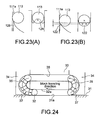
- the linear guide has, as illustrated in Fig. 24 , a track rail 31 having ball rolling grooves 31a formed therein, and a moving block 33 mounted on the track rail 31 via a plurality of balls 32 to be slidable along the track rail 31.
- a plurality of loaded ball rolling grooves 32a facing the ball rolling grooves of the track rail 31 and ball return paths 38 in parallel with the loaded ball rolling grooves 32a are formed.
- an end plate 34 is attached to each traveling-directional end of the moving block 33.
- a U-shaped direction change path 35 is formed connecting the loaded ball rolling grooves 32a and the ball return paths 38 extending in parallel with each other.
- These loaded ball rolling groove 32a, ball return path 38 and direction change path 35 constitute a circular ball circulation path.
- each ball After rolling in the ball rolling groove 31a of the track rail 31, each ball is scooped up by a scooping portion 37 at the lower end of the end plate 34 and enters the direction change path 35. Then, the ball passes through the ball return path 38 and the opposite-side direction change path 35, and then the ball is pushed by the following ball 32 to enter the ball rolling groove 31a at the scooping portion 37.
- the motion guide device as developed has a scooping portion 37 of which a tip end is cut off and a cut surface 37a is a flat surface perpendicular to the ball rolling groove 31a (see patent document 1).
- the sharp-pointed tie end of the scooping portion 37 is cur off, it is possible to enhance the strength of the scooping portion 37.
- the cut surface 37a is the flat surface perpendicular to the ball rolling groove 31a, it is difficult to circulate a ball 32 smoothly.
- Patent Document 1 Japanese Patent Laid-open Publication No. 2004-68880
- Non-Patent Document 1 Japanese Patent Application No. 2004-246524
- the center line 36 of the direction change path 35 seen in the axial direction of the track rail 31 usually agrees with the contact angle line L1 of the ball 32 (line connecting the center of the ball 32 and the bottom of the ball rolling groove, the definition of the contact angle line will be described later).
- the locus of the top of the Gothic arch groove shape is positioned on the contact angle line L1. Then, the ball 32 moves in the direction of the contact angle line L1 in the direction change path 35.
- the contact angle line L1 is sometimes required to be inclined relative to the direction change path 35.
- the right-side view of Fig. 26 shows the contact angle line which is inclined from L1 to L1' relative to the direction change path 35.
- the direction change path 35 is said to be inclined.
- the direction change path 35 is inclined relative to the contact angle line L1 in consideration of the space problem.
- a ball 32 is scooped up by one side 35a of the Gothic arch groove shape.
- the ball 32 is returned from the direction change path 35 to the ball rolling groove 31a, the ball is in contact only with the one side 35a of the Gothic arch groove shape.
- the ball 32 is always in contact with the one side 35a of two-side Gothic arch groove shape and is never in contact with the other side 35b.
- the Gothic arch groove shape produces little effect. Accordingly, when the ball is rolled at high speed, the scooping portion may be damaged.
- the present invention has an object to provide a motion guide device having a scooping portion which is not damaged even when the moving member is moved at high speed.
- the ball rolling groove of the track rail is sometimes formed having a shallow depth to enable smooth motion.
- a motion guide device having a scooping portion which is impervious to being damaged even when the moving member is moved at high velocity.
- Such a damage-proof scooping portion is desired in a motion guide device having a shallow ball rolling groove.
- the present invention has an object to provide a motion guide device having a ball rolling groove of shallow depth, a scooping portion of which is not damaged even when the moving member is moved at high speed.
- the invention of claim 1 is a motion guide device 1 comprising: a track member having a ball rolling groove formed therein; a moving member having formed therein a loaded ball rolling groove facing the ball rolling groove, a ball return path extending in parallel with the loaded ball rolling groove and a direction change path connecting the loaded ball rolling groove and the ball return path; and a plurality of balls arranged in a ball circulation path including the loaded ball rolling groove, the ball return path and the direction change path, after rolling in the ball rolling groove of the track member each of the balls being scooped up into the direction change path by a scooping portion of the direction change path, and the ball in the direction change path being returned to the ball rolling groove by the scooping portion, wherein the direction change path is inclined relative to a contact angle line (line connecting a center of the ball and a bottom of the ball rolling groove) when seen in an axial direction of the track member, the direction change path including the scooping portion has a cross section of Gothic arch groove shape formed of two arc
- the invention of claim 2 is characterized in that in the motion guide device according to claim 1, the direction change path has a twisting area and a non-twisting area, and a tangential direction of the locus of the top of the Gothic arch groove shape becomes continuous at a boundary between the twisting area and the non-twisting area.
- the invention of claim 3 is a motion guide device comprising: a track member having a ball rolling groove formed therein; a moving member having formed therein a loaded ball rolling groove facing the ball rolling groove, a ball return path extending in parallel with the loaded ball rolling groove and a direction change path connecting the loaded ball rolling groove and the ball return path; and a plurality of balls arranged in a ball circulation path including the loaded ball rolling groove, the ball return path and the direction change path, after rolling in the ball rolling groove of the track member each of the balls being scooped up into the direction change path by a scooping portion of the direction change path, and the ball in the direction change path being returned to the ball rolling groove by the scooping portion, wherein the direction change path is inclined relative to a contact angle line (line connecting a center of the ball and a bottom of the ball rolling groove) when seen in an axial direction of the track member, the scooping portion has a cross section of Gothic arch groove shape formed of two arcs so as to be in contact with the ball at two points, and a top
- the invention of claim 4 is a motion guide device comprising: a track member having a ball rolling groove formed therein; a moving member having formed therein a loaded ball rolling groove facing the ball rolling groove, a ball return path extending in parallel with the loaded ball rolling groove and a direction change path connecting the loaded ball rolling groove and the ball return path; and a plurality of balls arranged in a ball circulation path including the loaded ball rolling groove, the ball return path and the direction change path, after rolling in the ball rolling groove of the track member each of the balls being scooped up into the direction change path by a scooping portion of the direction change path, and the ball in the direction change path being returned to the ball rolling groove by the scooping portion, wherein in a cross section perpendicular to a rolling direction of the ball, the scooping portion has a Gothic arch groove shape so as to be in contact with the ball at two points, an angle formed by a line connecting a center of the ball rolling in the ball rolling groove of the track member and an edge of the ball rolling in the ball rolling groove of the track
- the invention of claim 5 is characterized in that in the motion guide device according to claim 4, an arc surface is formed, in a cross section taken along the rolling direction of the ball, at a contact start position where the scooping portion comes to be in contact with the ball when the scooping portion scoops up the ball rolling in the ball rolling groove of the track member.
- each ball is prevented from being in contact with only one side of the two-side Gothic arch groove shape.
- the scooping portion scoops up the ball with use of both sides of the Gothic arch groove shape and returns the ball from the direction change path into the ball rolling groove with use of the both sides of the Gothic arch groove shape. Hence, even when the moving member is moved at high speed, the scooping portion is prevented from being damaged.
- the tangential direction of the locus of the top of the Gothic arch groove shape is continuous at the boundary between the twisting area and the non-twisting area of the direction change path.
- each ball is prevented from being in contact with only one side of the two-side Gothic arch groove shape.
- the scooping portion scoops up the ball with use of both sides of the Gothic arch groove shape and returns the ball from the direction change path into the ball rolling groove with use of the both sides of the Gothic arch groove shape. Hence, even when the moving member is moved at high speed, the scooping portion is prevented from being damaged.
- the contact angle of the scooping portion is increased, the contact start position of each ball with the scooping portion when the ball is scooped by the scooping portion is shifted backward and upward. Accordingly, the thickness of the scooping portion is allowed to be increased, which enables enhancement of the strength of the scooping portion.
- Fig. 1 illustrates a motion guide device (ball spline) according to a first embodiment of the present invention.
- a track shaft 1 as a track member has an outer surface on which ball rolling grooves 1a are formed extending in the axial direction.
- a spline nut 2 as a moving member is inserted onto the track shaft 1.
- the spline nut 2 has an inner surface on which loaded ball rolling grooves 2a are formed facing the respective ball rolling grooves 1a (see the cross sectional view of Fig. 2 ).
- circular ball circulation paths 4 are formed in the spline nut 2.
- a plurality of balls 3 is arranged. Between each two of balls 3, a spacer 5 is arranged for preventing contact between the balls 3.
- a plurality of raised threads 1b is formed extending in the axial direction.
- one ball rolling groove 1a is formed extending in the axial direction of the track shaft 1.
- Each raised thread 1b is sandwiched between two ball rolling grooves 1a in order to bear torques on the spline nut 2.
- Each ball rolling groove 1a is a circular arc groove having a cross section formed of a single arc (see Fig. 4 ).
- the curvature radius of the ball rolling groove 1a is slightly larger than the radius of each ball 3.
- the ball rolling groove 1a and each ball 3 are in contact with each other at one point having a certain contact area.
- the line connecting the center C of the ball 3 and the bottom P1 of the ball rolling groove 1a is called contact angle line L1.
- the contact angle line L1 is described in detail later.
- the ball rolling groove 1a may be formed as a Gothic arch groove having a cross section formed of two arcs.
- the spline nut 2 inserted onto the track shaft 1 has a nut main body 6 having the loaded ball rolling grooves 2a, a retainer 7 mounted in the nut main body 6 to prevent balls 3 from dropping from the spline nut 2 and a pair of end plates 8 attached to respective ends in the travelling direction of the nut main body 6.
- each loaded ball rolling groove 2a of the nut main body 6 is formed as a circular arc groove having a cross section formed of a single arc or a Gothic arch groove having a cross section formed by two arcs.
- a ball return path 9 is formed in parallel with the loaded ball rolling groove 2a of the spline nut 2.
- the inner side of a U-shaped direction change path 10 is formed connecting the loaded ball rolling groove 2a and the ball return path 9.
- This retainer 7 holds balls 3 arranged in the loaded ball rolling groove 2a so as to prevent the balls 3 from dropping from the spline nut 2 when the spline nut 2 is removed from the track shaft 1.
- each end plate 8 the outer side of the direction change path 10 is formed.
- the retainer 7 and the end plate 8 are combined into the U-shaped direction change path 10.
- the loaded ball rolling groove 2a, the ball return path 9 and the paired direction change paths 10 consist in a circular ball circulation path.
- balls 3 roll, under load, in the axial direction, in the loaded rolling path between the ball rolling groove 1a and the loaded ball rolling groove 2a.
- each ball 3 is scooped up by a scooping portion formed in the direction change path 10 of an end plate 8 and is brought into the direction change path 10.
- the travelling direction of the ball 3 is reversed by the direction change path 10, and the ball 3 enters the ball return path 9.
- the direction of the ball 3 is reversed again by an opposite-side direction change path 10 and the ball 3 is returned from the scooping portion of the end plate 8 into the loaded rolling path.
- Figs. 3 (A) to 3 (C) illustrate an end plate 8.
- the outer side of the direction change path 10 is formed.
- the inner side of the direction change path 10 is formed in the retainer 7 as described above.
- the end plate 8 and the retainer 7 are combined to form the direction change path having an approximately circular cross section.
- projections 12 are provided to position the end plate 8 relative to the retainer 7.
- the end plate 8 is covered with a ring-shaped cover 14.
- screw holes 15 are formed for mounting the cover 14 to the end plate 8.
- the center line L2 of the direction change path 10 seen in the axial direction of the track shaft 1 does not agree with the contact angle line L1 and crosses the contact angle line L1 at the angle of ⁇ degree (for example, 45 degrees).
- the direction change path 10 is thus inclined so as to solve the problem of space. This embodiment approaches such a problem as arises when the direction change path 10 is thus inclined.
- Figs. 4(A) and 4(B) illustrate the contact angle line L1.
- the contact angle line L1 is a line connecting the center C of the ball 3 and the bottom P1 of the ball rolling groove 1a.
- the cross-sectional shape of the ball rolling groove 1a may be a circular arc groove shape of a single arc as shown in Fig. 4 (A) or a Gothic arch groove shape formed of two arcs as shown in Fig. 4(B) .
- the bottom P1 of the ball rolling groove agrees with the contact point C1 between the ball 3 and the ball rolling groove 1a.
- the contact angle line L1 in the case of the circular arc groove shape is defined as a line connecting the center C of the ball 3 and the contact point C1 between the ball 3 and the ball rolling groove 1a.
- the bottom P1 of the ball rolling groove 1a is shifted from the contact points C2 and C3 between the ball 3 and the two arcs, and matches the intersection of the two arcs.
- the contact angle line L1 in the case of the Gothic arch groove shape is defined as a line connecting the center of the ball 3 to the intersection P1 which is the bottom of the ball rolling groove 1a.
- Fig. 5 is a detailed view of the direction change path.
- the right side view of Fig. 5 is a front view of the direction change path 10 seen in the axial direction of the track shaft 1, while the left side view of Fig. 5 is a side view of the direction change path 10.
- the direction change path 10 has at its lower end a scooping portion 17, which scoops up each ball 3 rolling in the ball rolling groove 1a into the direction change path 10 and returns the ball 3 from the direction change path 10 into the ball rolling groove 1a.
- the cross section of the direction change path 10 in a plane perpendicular to the rolling direction of the ball 3 is shaped as a Gothic arch formed of two arcs. Therefore, the direction change path 10 and each ball 3 are in contact with each other at two points.
- the locus 18 of the top (intersection of the two arcs) of the Gothic arch groove is positioned at the outermost side of the direction change path 10. This is for bearing the force of the balls 3 pushing the direction change path 10 toward the outside by the centrifugal force.
- the direction change path 10 is twisted halfway as it becomes closer to the ball rolling groove 1a (lower end of the direction change path). Since the direction change path 10 is twisted, the locus 18 of the top of the Gothic arch groove goes away from the outermost locus 19 (shown by the broken line in the figure) as it is closer to the ball rolling groove 1a (lower end of the direction change path), and the locus 18 becomes closer to the contact angle line L1.
- the locus 18 of the top of the Gothic arch groove is ideally positioned on the contact angle line L1 ultimately.
- the cross section of Gothic arch groove has two arcs R1 and R1.
- the line L 13 connecting the center C of the ball 3 to the point P where the Gothic arch groove and the ball 3 are in contact with each other and the line L12 connecting the center C of the ball 3 to the bottom 23 of the Gothic arch groove crosses each other at the contact angle ⁇ 1 of more than 30 degrees (the angle ⁇ 1 is preferably set to range from 40 degrees to 60 degrees, inclusive).
- the contact angle ⁇ 1 is set in the same way. When the contact angle ⁇ 1 is increased, the thickness of the scooping portion 17 is allowed to be increased (this reason is given with description of Figs. 16 and 17 ).
- the locus of the top of the Gothic arch groove is gradually twisted.
- the middle point PC between the center points of the two arcs R1 of the Gothic arch groove shape is positioned a given distance A away from the ball rotational center for direction change, and the middle point PC is used as a center to draw an arc of ⁇ degree, and thereby the Gothic arch groove shape is formed.
- the line L3 connecting the center C of the ball 3 and the bottom 23 of the Gothic arch groove shape forms an angle of ⁇ degree relative to the center line L2 of the cross section of the direction change path 10.
- the angle ⁇ becomes 45 degrees and agrees with the inclination of the center line L2 of the direction change path relative to the contact angle line L1.
- this agreement is only shown in the J-J virtual cross section, and actually, as the tip end of the scooping portion 17 is displaced back from the end 20 of the ball rolling groove 1a, the center line L2 of the direction change path 10 is displaced from the contact angle line L1 correspondingly.
- Fig. 9 is a view taken along the arrows K-K of Fig. 3 (A) .
- the shape of the scooping portion 17 finally becomes as shown in this figure.
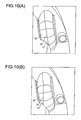
- Figs. 10(A) and 10(B) are views for comparing a conventional non-twisting locus 18 of the top of the Gothic arch groove shape ( Fig. 10 (A) ) with a twisting locus 18 of the present embodiment ( Fig. 10(B) ).
- the locus 18 is twisted toward the scooping portion 17.
- the shape of the scooping portion 17 is analogous to a symmetrical shape with respect to the locus 18.
- the twisting of the locus is also seen from the perspective view of the outer side of the direction change path 10 on Fig. 11 .
- the broken line shows the locus of the conventional design.
- the scooping portion 17 comes to scoop up each ball 3 in the direction of the contact angle line L1.
- the scooping portion 17 acts to scoop up the ball not at one, but equally both of the two arcs sides of the Gothic arch groove shape. Therefore, the scooping portion needs not bear any unnecessary force, and even if the spline nut 2 is moved at high speed, the scooping portion 17 is prevented from being damaged.
- Fig. 12 shows another example of the direction change path 10.
- the direction change path 10 to which the Gothic arch groove shape is transferred that is, a space that fits to the Gothic arch groove shape is shown.
- the direction change path 10 is divided into a twisting area S1 and a non-twisting area S2.
- the tangential direction of the locus 18 is continuous at the boundary 24 between the twisting area S1 and the non-twisting area S2.
- the tangential direction of the locus 18 is inclined gradually.
- the ultimate position of the locus 18 at the scooping portion 17 is the same as that of the locus 18 shown in Fig. 15 .
- Figs. 13 (A) to Fig. 14 (B) are used as a basis to explain the "continuous tangential direction of the locus 18".
- Figs. 13 (A) to 13(D) are detailed views of the above-mentioned direction change path.
- Fig. 13 (A) is a front view thereof
- Fig. 13(B) is a plane view thereof
- Fig. 13(C) is a left side view thereof
- Fig. 13(D) is a right side view thereof.
- the distance from the end of the direction change path 10 along the outer periphery of the direction change path 10 is r.
- an angle formed by the tangential direction t1 of the locus 18 and the virtual locus 25 on the assumption that the direction change path 10 is not twisted is indicated by the inclination ⁇ .
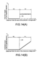
- Figs. 14(A) and 14(B) are graphs showing the relation between the distance r and the inclination ⁇ .
- Fig. 14(A) is a graph of the comparative example where the tangential direction of the locus 18 is discontinuous
- Fig. 14(B) is a graph of the example where the tangential direction of the locus 18 is continuous as shown in Fig. 12 and Figs. 13(A) to 13(D).
- the locus 18 shown in Fig. 15 is inclined abruptly at the boundary between the twisting area and the non-twisting are of the direction change path 10 and linearly at a certain angle. As the locus is thus inclined, the inclination ⁇ becomes discontinuous at the boundary 24 between the twisting area S1 and the non-twisting area S2.
- the present invention is not limited to the above-mentioned first embodiment and may be embodied in various forms without departing from the scope of the present invention.
- the present invention is not limited to a ball spline but may be applied to a linear guide as long as the direction change path is inclined relative to the contact angle line when seen in the axial direction of the track member.
- the Gothic arch groove may not be formed over the whole length of each direction change path or may be formed in at least a part of the direction change path including the scooping portion.
- the cross-sectional shape is preferably changed from the Gothic arch groove shape to the circular arc groove shape gradually.
- the cross-sectional shape of the ball return path is formed as a circle, if the connection point of the ball return path and the direction change path is shaped having a circular arc groove, the cross-sectional shape of the direction change path and the cross-sectional shape of the ball return path can conform to each other. This enables smooth circulation of balls.
- Fig. 15 illustrates a linear guide as a motion guide device according to a second embodiment of the present invention.
- the applicant has proposed a scooping portion of a linear guide having a ball rolling groove of shallow depth.
- the scooping portion of this embodiment is applicable to the ball spline of the first embodiment.
- Fig. 15 is a perspective view of the linear guide.
- This linear guide has a track rail 111 as a track member elongating straightly and a saddle-shaped moving block 112 as a moving member mounted on the track rail 111 slidablely relative the track rail 111. Between the track rail 111 and the moving block 112, there are a large number of balls 113 arranged rollably.
- the track rail 111 has an approximately quadrangular shaped cross section, and on the upper portions of both side surfaces and on the upper-surface side portions of the track rail 111, totally four ball rolling grooves 11a are formed.
- Each ball rolling groove 111a elongates in the longitudinal direction of the track rail 111 and is formed like a circular arc groove having a cross section formed of a single arc.
- the moving block 112 has a center portion 112a facing the upper surface of the track rail 111 and side wall portions 112b, 112b extending downward from the both sides of the center portion 112a and facing the side surfaces of the track rail 111, and the moving block 112 is shaped like a saddle as a whole.
- This moving block 112 has a steel moving block main body 114 and end plates attached to respective end surfaces in the moving direction of the moving block main body 114.
- each loaded ball rolling groove 114a is formed like a circular arc groove having a single arc, and totally four loaded ball rolling grooves 114a are formed corresponding to the ball rolling grooves 111a.
- Each ball 113 moves rolling under load between a ball rolling groove 111a of the track rail 111 and a loaded ball rolling groove 114a of the moving block main body 114.
- ball return paths 117 are formed of through holes in parallel with and spaced a given distance from the respective loaded ball rolling grooves 114a.
- resin-made R pieces formed integral with the moving block main body 114, each of which connects a loaded ball rolling groove 114a and a corresponding ball return path 117 and constitutes an inner side of the U-shaped direction change path 121 (see Fig. 20 ).
- an outer side of the U-shaped direction change path 121 is formed (see Fig. 20 ).
- the outer side 120 of the direction change path 121 formed in the end plate 115 and a scooping portion 122 are described later.
- Each ball return path 117 of the moving block 112 and the direction change path 121 constitute a non-loaded ball return path.
- a loaded ball rolling path 123 is formed (see Fig. 20 ).
- the loaded ball rolling path 123, the direction change paths 121 and the ball return path 117 consist in a circular ball circulation path.
- a large number of balls 113 are arranged in the loaded ball rolling path 123, the non-loaded ball return paths 117 and the direction change paths 121.
- the balls 113 are held in a chain and rollably by a ball retaining band 124.
- the ball retaining band 124 has spacers 124a interposed between two balls 113 and flexible belts 124b for connecting the spacers 124a.
- Each adjacent two balls 113 are not in contact with each other and held by the ball retaining band 124 while circulating in the ball circulation path.
- each end plate 115 there is an end seal 125 attached.
- the end seal 125 is provided for preventing foreign matters, water and the like attached to the upper surface and the side surfaces of the track rail 111 from entering the inside of the moving block 112 and also for preventing a lubricant inside the moving block 112 from leaking to the outside.
- Figs. 16(A) to 17(B) are views for comparing a conventional end plate 127 and an end plate 115 of this embodiment.
- Figs. 16(A) and 16(B) show the direction change path 121a to the upper-surface side of the track rail 111 (showing a cross section thereof) and the direction change path 121b to the side-surface side of the track rail 111.
- Figs. 17 (A) and 17(B) are perspective views of the direction change path 121a arranged to the upper-surface side of the track rail 111, seen from the moving block main body side.
- Figs. 16 (A) and 17 (A) are of the conventional end plate 127 and
- Fig. 16 (B) and 17 (B) are of the end plate 115 of this embodiment.
- a scooping portion 122 for scooping each ball 113 rolling in the ball rolling groove 111a of the track rail 111 and bringing the ball 113 to the direction change path 121a.
- the moving block 112 moves at low speed (for example, at a speed of less than 150 m/min)
- even a scooping portion 128 of the conventional end plate 127 is hardly damaged.
- the moving clock 112 moves at high speed (for example, at a speed of 150 m/min or higher)
- the conventional scooping portion 128 may be damaged.
- the tip end of the scooping portion 122 is formed back in the ball rolling direction (1) in this embodiment as compared with the scooping portion 128 of the conventional end plate.
- the thus-formed scooping portion 122 is also seen in Fig. 17 .
- Fig. 18 illustrates a detailed view of the end plate 115.
- the direction change path 121a and direction change path 121b are the same as those described above.
- the outer side of the direction change path 121a is formed in the end plate 115.
- the outer side of the direction change path 121a is circumferentially comprised of a circular arc groove area 131 formed of a single arc, a Gothic arch groove area 133 having two arcs so as to be in contact with each ball 113 and a groove transition area 132 provided between the circular arc groove area 131 and the Gothic arch groove area 133 in which the groove shape gradually changes from the circular arc groove to the Gothic arch groove.
- the direction change path 121a may be formed only of the Gothic arch groove.
- the circular arc groove area 131 is an area where the groove has a cross section formed of a single arc. This circular arc groove area 131 is formed 45 degrees in the circumferential direction of the direction change path 121a. As shown in the H-H cross section in the figure, the circular arc groove area 131 consists of a single arc having a radius RC which is in agreement with the radius of the ball return path 117 of the moving block main body 114 (the radius Rc is slightly larger than the radius of each ball).
- the groove transition area 132 is an area where the groove shape changes from the Gothic arch groove to the circular arc groove.
- the groove transition area 132 is formed, for example, 90 degrees in the circumferential direction of the direction change path 121a.
- the Gothic arch groove 133 is an area where the groove shape has a cross section of two arcs so that each ball 113 is in contact with the groove at two points.
- the Gothic arch groove area 133 is formed, for example, 20 degrees in the circumferential direction of the direction change path 121a.
- the curvature radius Ra of the two arcs is larger than the radius of each ball 113.
- the Gothic arch groove shape is symmetric with respect to the center line, and the center pitch of two curves of the curvature radius Ra and the center position are determined in such a manner that the contact angle ⁇ 1 is for example 45 degrees.
- the bottom of the groove is rounded having a curvature radius Rb.
- the scooping portion 122 is formed at the lower end of the Gothic arch groove area 133.
- the L-L virtual cross section of the figure shows the shape of the scooping portion 122 seen in the ball rolling direction of each ball 113.
- the tip end of the scooping portion 122 has a Gothic arch groove shape having a cross section of two arcs so as to be e in two-point contact with ach ball 113.
- the curvature radius Ra of two arcs is equal to the curvature radius of two arcs of the Gothic arch groove area 133.
- an arc surface Rd is formed at the contact start position between the ball 113 and the scooping portion 122 (see Fig. 21 ). Accordingly, at the tip end of the scooping portion 122, the center pitch of two arcs of curvature radius Ra becomes shorter than the center pitch of the Gothic arch groove area 133. Then, the center between the two curves of curvature radius Ra is positioned to the radially outer side of the direction change path 121a from the center position of the Gothic arch groove area 133.
- the contact angle of the tip end of the scooping portion 122 becomes smaller than the contact angle of the Gothic arch groove area 133.
- the contact angle is reduced from 45 degrees to 41 degrees.
- the groove shape of the scooping portion 122 changes, in the scooping portion groove transition area 134, from the F-F cross section shape to the L-L virtual cross section shape continuously.
- Fig. 19 shows the definition of the contact angle ⁇ 1.
- the contact angle ⁇ 1 is defined, in the cross section perpendicular to the ball rolling direction of each ball 113, as an angle formed by the line L11 connecting the point P at which the scooping portion 122 is in contact with each ball 113 and the center C of the ball 113 and the line L12 connecting the center C of the ball 113 and the bottom 122a of the Gothic arch groove shaped scooping portion 122.
- the contact angle ⁇ 1 of the scooping portion 122 in the Gothic arch groove area 133 exceeds 30 degrees.
- the contact angle preferably ranges from 40 degrees to 60 degrees, inclusive. In this embodiment, the angle is set to 45 degrees as shown in Fig. 18 .
- the angle ⁇ 1 formed by the lines L13 and L12 is 30 degrees or less. This is because the ball rolling groove 111a has a shallow depth.
- Fig. 20 shows a relation between the contact angle ⁇ 1 and the contact start position (position at which each ball 113 rolling in the ball rolling groove 111a of the track rail 111 comes into contact with the scooping portion 122 when the ball 113 is scooped up by the scooping portion 122).
- the contact start position As shown in the table 1, when the contact angle ⁇ 1 varies from 30 degrees to 45 degrees, then to 60 degrees, the contact start position also changes like (1) ⁇ (2) ⁇ (3) as shown in Fig. 20 .
- the contact start positions (1), (2) and (3) are also shifted upward and backward in the ball rolling direction. With this movement, the scooping portion becomes thicker and its strength is enhanced thereby obtaining high-speed capability.
- the front end 122b of the scooping portion 122 can be shifted backward, and thereby it is possible to reduce damage on the scooping portion 122 during high-speed operation.
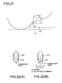
- Fig. 21 shows a cross section of the scooping portion 122 taken along the rolling direction of each ball 113.
- the ball 113 and the scooping portion 122 are in contact with each other at two points, and the cross section shown in Fig. 21 is of a plane including one of the two contact points.
- the scooping portion 122 is only cur off at its tip end, the scooping angle ⁇ 1 measured when the ball 113 is scooped up will become larger.
- the arc surface of radius Rd is formed at the contact start position by chamfering.
- Figs. 22(A) to 23(B) are views for comparing a contact state between each ball 113 with the tip end of the conventional scooping portion 128 and a contact state between the ball 113 and the scooping portion 122 of the present embodiment.
- Fig. 22 (A) shows the conventional end plate 127 and Fig. 22 (B) shows the end plate 115 of this embodiment.
- Fig. 23(A) shows the conventional scooping portion 128 and Fig. 23(B) shows the scooping portion 122 of this embodiment.
- the conventional end plate 127 the ball 113 is in one-point contact with the scooping portion 128 at the contact start position and the ball 113 is in one-point contact with the ball rolling groove 111a.
- the ball 113 is in two-point contact with the scooping portion 122 at the contact start position and the ball 113 is one-point contact with the ball rolling groove 111a.
- the contact angle ⁇ 1 at the contact start position of the scooping portion 122 becomes 41 degrees, smaller than 45 degrees.
- the present invention is not limited to the above-mentioned second embodiment and may be embodied in various forms without departing from the scope of the present invention.
- the present invention is not limited to a linear guide having a groove of shallow depth, and may be applied to a ball spline having a groove of shallow depth.
- the inventors of this application manufactured a ball spline according to the first embodiment and conducted a high-speed durability test.
- the scooping portion was damaged at 1,000 km, however, for a high-speed capable end cap the scooping portion was not damaged even after 10,000 km of moving.
Landscapes
- Engineering & Computer Science (AREA)
- General Engineering & Computer Science (AREA)
- Mechanical Engineering (AREA)
- Bearings For Parts Moving Linearly (AREA)
- Transmission Devices (AREA)
Abstract
Description
- The present invention relates to a motion guide device having a moving member moving relative to a track member, such as a linear guide, a ball spline and the like.
- A motion guide device is mounted in a robot, a machine tool or a semiconductor/liquid crystal manufacturing apparatus and is used to guide linear movement or curvilinear movement of a moving body.
- Known as a motion guide device are a linear guide, a ball spline and the like. The linear guide has, as illustrated in
Fig. 24 , atrack rail 31 havingball rolling grooves 31a formed therein, and a movingblock 33 mounted on thetrack rail 31 via a plurality ofballs 32 to be slidable along thetrack rail 31. In the movingblock 33, a plurality of loadedball rolling grooves 32a facing the ball rolling grooves of thetrack rail 31 andball return paths 38 in parallel with the loadedball rolling grooves 32a are formed. To each traveling-directional end of the movingblock 33, anend plate 34 is attached. In theend plate 34, a U-shapeddirection change path 35 is formed connecting the loadedball rolling grooves 32a and theball return paths 38 extending in parallel with each other. These loadedball rolling groove 32a,ball return path 38 anddirection change path 35 constitute a circular ball circulation path. - After rolling in the
ball rolling groove 31a of thetrack rail 31, each ball is scooped up by a scoopingportion 37 at the lower end of theend plate 34 and enters thedirection change path 35. Then, the ball passes through theball return path 38 and the opposite-sidedirection change path 35, and then the ball is pushed by the followingball 32 to enter theball rolling groove 31a at thescooping portion 37. - In such a motion guide device, when the moving
block 33 is moved at high speed, thescooping portion 37 at the lower end of theend plate 34 is sometimes damaged, which is a problem. This damage is caused because when theball 32 rolls from thedirection change path 35 into theball rolling groove 31a, theball 32 pushes the scoopingportion 37 outward by a centrifugal force or theball 32 is pushed near thescooping portion 37 toward the outside of the scoopingportion 37 by a meandering follow-onball 32. Besides, when theball 32 is scooped up from theball rolling groove 31a, a scooping force is applied to the scoopingportion 37. - In order to solve this problem, there has been developed a motion guide device of which a scooping portion is hardly damaged even when the motion guide device is operated at high speed. For example, as shown in
Fig. 25 , the motion guide device as developed has a scoopingportion 37 of which a tip end is cut off and acut surface 37a is a flat surface perpendicular to theball rolling groove 31a (see patent document 1). According to the invention disclosed in thepatent document 1, as the sharp-pointed tie end of the scoopingportion 37 is cur off, it is possible to enhance the strength of the scoopingportion 37. However, as thecut surface 37a is the flat surface perpendicular to theball rolling groove 31a, it is difficult to circulate aball 32 smoothly. - Meanwhile, the applicant has devised a motion guide device with a scooping portion which has a Gothic arch groove shaped cross section formed of two arcs in such a manner as to be in contact with each ball at two points (see non-patent document 1). According to this invention, it is possible to prevent damage to the scooping portion while allowing smooth circulation of balls.
[Patent Document 1] Japanese Patent Laid-open Publication No.2004-68880
[Non-Patent Document 1] Japanese Patent Application No.2004-246524 - In the meantime, in a motion guide device such as a linear guide, a ball spline or the like, as shown in the left-side view of
Fig. 26 , thecenter line 36 of thedirection change path 35 seen in the axial direction of thetrack rail 31 usually agrees with the contact angle line L1 of the ball 32 (line connecting the center of theball 32 and the bottom of the ball rolling groove, the definition of the contact angle line will be described later). In this case, the locus of the top of the Gothic arch groove shape is positioned on the contact angle line L1. Then, theball 32 moves in the direction of the contact angle line L1 in thedirection change path 35. - However, in view of the space problem, the contact angle line L1 is sometimes required to be inclined relative to the
direction change path 35. The right-side view ofFig. 26 shows the contact angle line which is inclined from L1 to L1' relative to thedirection change path 35. When seen from the contact angle line L1', thedirection change path 35 is said to be inclined. For example, in a linear guide shown inFig. 27 , thedirection change path 35 is inclined relative to the contact angle line L1 in consideration of the space problem. - When the
direction change path 35 is inclined and still has a Gothic arch groove shape, as shown inFig. 26 , aball 32 is scooped up by oneside 35a of the Gothic arch groove shape. When theball 32 is returned from thedirection change path 35 to theball rolling groove 31a, the ball is in contact only with the oneside 35a of the Gothic arch groove shape. In other words, theball 32 is always in contact with the oneside 35a of two-side Gothic arch groove shape and is never in contact with theother side 35b. With this structure, the Gothic arch groove shape produces little effect. Accordingly, when the ball is rolled at high speed, the scooping portion may be damaged. - Then, the present invention has an object to provide a motion guide device having a scooping portion which is not damaged even when the moving member is moved at high speed.
- In addition, in a motion guide device such as a linear guide, a ball spline or the like, the ball rolling groove of the track rail is sometimes formed having a shallow depth to enable smooth motion. The applicant has proposed, in the above-mentioned
non-patent document 1, a motion guide device having a scooping portion which is impervious to being damaged even when the moving member is moved at high velocity. Such a damage-proof scooping portion is desired in a motion guide device having a shallow ball rolling groove. - Then, the present invention has an object to provide a motion guide device having a ball rolling groove of shallow depth, a scooping portion of which is not damaged even when the moving member is moved at high speed.
- The present invention will now be described below.
- In order to solve the above-mentioned problems, the invention of
claim 1 is amotion guide device 1 comprising: a track member having a ball rolling groove formed therein; a moving member having formed therein a loaded ball rolling groove facing the ball rolling groove, a ball return path extending in parallel with the loaded ball rolling groove and a direction change path connecting the loaded ball rolling groove and the ball return path; and a plurality of balls arranged in a ball circulation path including the loaded ball rolling groove, the ball return path and the direction change path, after rolling in the ball rolling groove of the track member each of the balls being scooped up into the direction change path by a scooping portion of the direction change path, and the ball in the direction change path being returned to the ball rolling groove by the scooping portion, wherein the direction change path is inclined relative to a contact angle line (line connecting a center of the ball and a bottom of the ball rolling groove) when seen in an axial direction of the track member, the direction change path including the scooping portion has a cross section of Gothic arch groove shape formed of two arcs in such a manner that the ball is in contact with the direction change path at two points, and the direction change path is twisted in such a manner that a locus of top of the Gothic arch groove shape approaches the contact angle line at the scooping portion. - The invention of
claim 2 is characterized in that in the motion guide device according toclaim 1, the direction change path has a twisting area and a non-twisting area, and a tangential direction of the locus of the top of the Gothic arch groove shape becomes continuous at a boundary between the twisting area and the non-twisting area. - The invention of
claim 3 is a motion guide device comprising: a track member having a ball rolling groove formed therein; a moving member having formed therein a loaded ball rolling groove facing the ball rolling groove, a ball return path extending in parallel with the loaded ball rolling groove and a direction change path connecting the loaded ball rolling groove and the ball return path; and a plurality of balls arranged in a ball circulation path including the loaded ball rolling groove, the ball return path and the direction change path, after rolling in the ball rolling groove of the track member each of the balls being scooped up into the direction change path by a scooping portion of the direction change path, and the ball in the direction change path being returned to the ball rolling groove by the scooping portion, wherein the direction change path is inclined relative to a contact angle line (line connecting a center of the ball and a bottom of the ball rolling groove) when seen in an axial direction of the track member, the scooping portion has a cross section of Gothic arch groove shape formed of two arcs so as to be in contact with the ball at two points, and a top of the Gothic arch groove shape at the scooping portion is positioned in proximity to the contact angle line. - The invention of
claim 4 is a motion guide device comprising: a track member having a ball rolling groove formed therein; a moving member having formed therein a loaded ball rolling groove facing the ball rolling groove, a ball return path extending in parallel with the loaded ball rolling groove and a direction change path connecting the loaded ball rolling groove and the ball return path; and a plurality of balls arranged in a ball circulation path including the loaded ball rolling groove, the ball return path and the direction change path, after rolling in the ball rolling groove of the track member each of the balls being scooped up into the direction change path by a scooping portion of the direction change path, and the ball in the direction change path being returned to the ball rolling groove by the scooping portion, wherein in a cross section perpendicular to a rolling direction of the ball, the scooping portion has a Gothic arch groove shape so as to be in contact with the ball at two points, an angle formed by a line connecting a center of the ball rolling in the ball rolling groove of the track member and an edge of the ball rolling in the ball rolling groove of the track member and a line connecting the center of the ball and a bottom of the ball rolling groove of the track member is 30 degrees or less, and an angle (contact angle) formed by a line connecting the center of the ball and a contact point between the scooping portion and the ball and a line connecting the center of the ball and a bottom of the Gothic arch groove shape exceeds 30 degrees. - The invention of
claim 5 is characterized in that in the motion guide device according toclaim 4, an arc surface is formed, in a cross section taken along the rolling direction of the ball, at a contact start position where the scooping portion comes to be in contact with the ball when the scooping portion scoops up the ball rolling in the ball rolling groove of the track member. - According to the invention of
claim 1, even if the direction change path is inclined relative to the contact angle line, each ball is prevented from being in contact with only one side of the two-side Gothic arch groove shape. In other words, the scooping portion scoops up the ball with use of both sides of the Gothic arch groove shape and returns the ball from the direction change path into the ball rolling groove with use of the both sides of the Gothic arch groove shape. Hence, even when the moving member is moved at high speed, the scooping portion is prevented from being damaged. - According to the invention of
claim 2, the tangential direction of the locus of the top of the Gothic arch groove shape is continuous at the boundary between the twisting area and the non-twisting area of the direction change path. With this structure, a ball in two-point contact with the Gothic arch groove does not change its rolling direction abruptly but gradually. Therefore, smooth circulation of the ball is allowed. - According to the invention of
claim 3, even if the direction change path is inclined relative to the contact angle line, each ball is prevented from being in contact with only one side of the two-side Gothic arch groove shape. In other words, the scooping portion scoops up the ball with use of both sides of the Gothic arch groove shape and returns the ball from the direction change path into the ball rolling groove with use of the both sides of the Gothic arch groove shape. Hence, even when the moving member is moved at high speed, the scooping portion is prevented from being damaged. - According to the invention of
claim 4, as the contact angle of the scooping portion is increased, the contact start position of each ball with the scooping portion when the ball is scooped by the scooping portion is shifted backward and upward. Accordingly, the thickness of the scooping portion is allowed to be increased, which enables enhancement of the strength of the scooping portion. - When the contact start position of each ball with the scooping portion when the ball is scooped by the scooping portion is shifted backward in the ball rolling direction, a scooping angle becomes larger. According to the invention of
claim 5, as the arch surface is formed at the contact start position, the scooping angle is allowed to be gentle. -
-
Fig. 1 is a perspective view illustrating a ball spline according to a first embodiment of the present invention; -
Fig. 2 is a cross sectional view of the ball spline taken along the axial line; -
Figs. 3(A) to 3(C) are views each illustrating an end plate (Fig. 3(A) being a back side view,Fig. 3(B) being a side view andFig. 3(C) being a front view); -
Figs. 4(A) to 4(B) are views showing the definitions of the contact angle line (Fig. 4(A) showing the contact angle line of the circular arc groove shape, andFig. 4(B) showing the contact angle line of the Gothic arch groove shape); -
Fig. 5 is a detailed view of the direction change path; -
Fig. 6 is a detailed view of the direction change path; -
Fig. 7 is a detailed view of the F part inFig. 6 ; -
Fig. 8 is a detailed view of the B part inFig. 6 ; -
Fig. 9 is a view taken along the arrows K-K inFig. 3 (A) ; -
Figs. 10(A) to 10(B) are perspective views of the direction change path (Fig. 10(A) showing a conventional non-twisting locus of the top of the Gothic arch groove shape andFig. 10 (B) showing a twisting locus of the top of the Gothic arch groove shape); -
Fig. 11 is a perspective view of the outer side of the direction change path; -
Fig. 12 is a perspective view showing another example of the direction change path; -
Figs. 13(A) to 13(D) are detailed views of the direction change path ofFig. 12 (Fig. 13(A) being a front view,Fig. 13(B) being a plane view,Fig. 13(C) being a left side view andFig. 13(D) being a right side view); -
Figs. 14(A) to 14(B) are graphs showing the relation between the distance r and the inclination θ (Fig. 14 (A) being of a conventional example in which the tangential direction of the locus is not continuous andFig. 14 (B) being of an example where the tangential direction of the locus is continuous); -
Fig. 15 is a perspective view illustrating a linear guide as a second motion guide device of the present invention; -
Figs. 16(A) to 16(B) are cross sectional views for comparing a conventional end plate with an end plate of this embodiment (Figs. 16(A) showing the conventional end plate andFig. 16(B) showing the end plate of this embodiment); -
Figs. 17(A) to 17(B) are perspective views for comparing a conventional end plate with an end plate of this embodiment (Figs. 17(A) showing the conventional end plate andFig. 17(B) showing the end plate of this embodiment); -
Fig. 18 is a detailed view of the end plate; -
Fig. 19 is a view showing the definition of the contact angle; -
Fig. 20 is a view showing the relation between the contact angle and the contact start position; -
Fig. 21 is a cross sectional view of the scooping portion taken along the ball rolling direction; -
Figs. 22(A) to 22(B) are views of the contact state of a ball with a tip end of a scooping portion, comparing a conventional scoping portion with a scooping portion of this embodiment (Figs. 22(A) showing the conventional end plate andFig. 22(B) showing the end plate of this embodiment); -
Figs. 23(A) to 23(B) are detailed views of the scooping portion (Figs. 23(A) showing a conventional scooping portion, andFig. 23(B) showing a scooping portion of this embodiment) ; -
Fig. 24 is a cross sectional view illustrating a conventional motion guide device; -
Fig. 25 is a cross sectional view illustrating a conventional scooping portion; -
Fig. 26 is a view showing inclination of the direction change path seen in the axial direction of the track rail (conventional example); and -
Fig. 27 is a cross sectional view showing a linear guide having an inclined direction change path (conventional example). -
- 1
- track shaft (track member)
- 1a
- ball rolling groove
- 2
- spline nut (moving member)
- 2a
- loaded ball rolling groove
- 3
- ball
- 4
- ball circulation path
- 9
- ball return path
- 10
- direction change path
- 17
- scooping portion
- 18
- locus
- 21
- top
- 24
- boundary
- S1
- twisting area
- S2
- non-twisting area
- t1
- tangential direction of the locus
- 111
- track rail (track member)
- 111a
- ball rolling groove
- 112
- moving block (moving member)
- 113
- ball
- 114
- moving block main body
- 114a
- loaded ball rolling groove
- 115
- end plate
- 117
- ball return path
- 121, 121a, 121b
- direction change path
- 122
- scooping portion
- 122a
- bottom of scooping portion
- 135
- edge
- With reference to the attached drawings, the present invention will now be described in detail below.
Fig. 1 illustrates a motion guide device (ball spline) according to a first embodiment of the present invention. Atrack shaft 1 as a track member has an outer surface on whichball rolling grooves 1a are formed extending in the axial direction. Aspline nut 2 as a moving member is inserted onto thetrack shaft 1. Thespline nut 2 has an inner surface on which loadedball rolling grooves 2a are formed facing the respectiveball rolling grooves 1a (see the cross sectional view ofFig. 2 ). In order to enable ball circulation, circularball circulation paths 4 are formed in thespline nut 2. In theseball circulation paths 4, a plurality ofballs 3 is arranged. Between each two ofballs 3, aspacer 5 is arranged for preventing contact between theballs 3. - On the surface of the
track shaft 1, a plurality of raisedthreads 1b is formed extending in the axial direction. At each side of each raisedthread 1b, oneball rolling groove 1a is formed extending in the axial direction of thetrack shaft 1. Each raisedthread 1b is sandwiched between twoball rolling grooves 1a in order to bear torques on thespline nut 2. - Each
ball rolling groove 1a is a circular arc groove having a cross section formed of a single arc (seeFig. 4 ). The curvature radius of theball rolling groove 1a is slightly larger than the radius of eachball 3. Theball rolling groove 1a and eachball 3 are in contact with each other at one point having a certain contact area. The line connecting the center C of theball 3 and the bottom P1 of theball rolling groove 1a is called contact angle line L1. The contact angle line L1 is described in detail later. Here, theball rolling groove 1a may be formed as a Gothic arch groove having a cross section formed of two arcs. - As shown in
Fig. 1 , thespline nut 2 inserted onto thetrack shaft 1 has a nutmain body 6 having the loadedball rolling grooves 2a, a retainer 7 mounted in the nutmain body 6 to preventballs 3 from dropping from thespline nut 2 and a pair ofend plates 8 attached to respective ends in the travelling direction of the nutmain body 6. - The cross-sectional shape of each loaded
ball rolling groove 2a of the nutmain body 6 is formed as a circular arc groove having a cross section formed of a single arc or a Gothic arch groove having a cross section formed by two arcs. - In the retainer 7, a
ball return path 9 is formed in parallel with the loadedball rolling groove 2a of thespline nut 2. Besides, in this retainer 7, the inner side of a U-shaped direction changepath 10 is formed connecting the loadedball rolling groove 2a and theball return path 9. This retainer 7 holdsballs 3 arranged in the loadedball rolling groove 2a so as to prevent theballs 3 from dropping from thespline nut 2 when thespline nut 2 is removed from thetrack shaft 1. - In each
end plate 8 the outer side of the direction changepath 10 is formed. The retainer 7 and theend plate 8 are combined into the U-shaped direction changepath 10. - The loaded
ball rolling groove 2a, theball return path 9 and the paireddirection change paths 10 consist in a circular ball circulation path. When thespline nut 2 is moved relative to thetrack shaft 1,balls 3 roll, under load, in the axial direction, in the loaded rolling path between theball rolling groove 1a and the loadedball rolling groove 2a. Once reaching one end of the loaded rolling path, eachball 3 is scooped up by a scooping portion formed in the direction changepath 10 of anend plate 8 and is brought into the direction changepath 10. Then, the travelling direction of theball 3 is reversed by the direction changepath 10, and theball 3 enters theball return path 9. After theball 3 has passed through theball return path 9, the direction of theball 3 is reversed again by an opposite-side direction changepath 10 and theball 3 is returned from the scooping portion of theend plate 8 into the loaded rolling path. -
Figs. 3 (A) to 3 (C) illustrate anend plate 8. In theback surface 8a of theend plate 8, the outer side of the direction changepath 10 is formed. The inner side of the direction changepath 10 is formed in the retainer 7 as described above. Theend plate 8 and the retainer 7 are combined to form the direction change path having an approximately circular cross section. In theback surface 8a of theend plate 8,projections 12 are provided to position theend plate 8 relative to the retainer 7. Besides, in theend plate 8, there are throughholes 13 formed for mounting theend plate 8 onto the retainer 7. As shown inFig. 1 , theend plate 8 is covered with a ring-shapedcover 14. In thefront surface 8b of theend plate 8, screw holes 15 are formed for mounting thecover 14 to theend plate 8. - As shown in
Fig. 3(A) , the center line L2 of the direction changepath 10 seen in the axial direction of thetrack shaft 1 does not agree with the contact angle line L1 and crosses the contact angle line L1 at the angle of θ degree (for example, 45 degrees). In some ball splines and linear guides, the direction changepath 10 is thus inclined so as to solve the problem of space. This embodiment approaches such a problem as arises when the direction changepath 10 is thus inclined. - Before the shape of the direction change
path 10 of theend plate 8 is described in detail, the contact angle line L1 is defined and the basic design idea of the direction changepath 10 is explained. -
Figs. 4(A) and 4(B) illustrate the contact angle line L1. The contact angle line L1 is a line connecting the center C of theball 3 and the bottom P1 of theball rolling groove 1a. The cross-sectional shape of theball rolling groove 1a may be a circular arc groove shape of a single arc as shown inFig. 4 (A) or a Gothic arch groove shape formed of two arcs as shown inFig. 4(B) . In the case of the circular arc groove shape, the bottom P1 of the ball rolling groove agrees with the contact point C1 between theball 3 and theball rolling groove 1a. Hence, the contact angle line L1 in the case of the circular arc groove shape is defined as a line connecting the center C of theball 3 and the contact point C1 between theball 3 and theball rolling groove 1a. On the other hand, in the case of the Gothic arch groove shape, the bottom P1 of theball rolling groove 1a is shifted from the contact points C2 and C3 between theball 3 and the two arcs, and matches the intersection of the two arcs. The contact angle line L1 in the case of the Gothic arch groove shape is defined as a line connecting the center of theball 3 to the intersection P1 which is the bottom of theball rolling groove 1a. -
Fig. 5 is a detailed view of the direction change path. The right side view ofFig. 5 is a front view of the direction changepath 10 seen in the axial direction of thetrack shaft 1, while the left side view ofFig. 5 is a side view of the direction changepath 10. Thedirection change path 10 has at its lower end a scoopingportion 17, which scoops up eachball 3 rolling in theball rolling groove 1a into the direction changepath 10 and returns theball 3 from the direction changepath 10 into theball rolling groove 1a. - Over the whole length of the direction change
path 10, the cross section of the direction changepath 10 in a plane perpendicular to the rolling direction of theball 3 is shaped as a Gothic arch formed of two arcs. Therefore, the direction changepath 10 and eachball 3 are in contact with each other at two points. Thelocus 18 of the top (intersection of the two arcs) of the Gothic arch groove is positioned at the outermost side of the direction changepath 10. This is for bearing the force of theballs 3 pushing the direction changepath 10 toward the outside by the centrifugal force. - Then, the direction change
path 10 is twisted halfway as it becomes closer to theball rolling groove 1a (lower end of the direction change path). Since the direction changepath 10 is twisted, thelocus 18 of the top of the Gothic arch groove goes away from the outermost locus 19 (shown by the broken line in the figure) as it is closer to theball rolling groove 1a (lower end of the direction change path), and thelocus 18 becomes closer to the contact angle line L1. Thelocus 18 of the top of the Gothic arch groove is ideally positioned on the contact angle line L1 ultimately. However, as the scoopingportion 17 of the direction changepath 10 is slightly shifted back from theend 20 of theball rolling groove 1a, the top 21 at the tip end of the scoopingportion 17 does not reach the contact angle line L1 and is slightly shifted thereform as shown in the right side view ofFig. 5 . This is also clear fromFig. 6 explained below. -
Fig. 6 is a detailed view showing the direction changepath 10 of an actually designedend plate 8. As shown in the B-B cross section, the direction changepath 10 is divided into a left-side area where the locus of the top of the Gothic arch groove is not twisted (non-twisting area) and a right-side area (twisting area) (area of α = 0 to 90 degrees). - As shown in the F-F cross section on
Fig. 6 and its detailed view onFig. 7 , the cross section of Gothic arch groove has two arcs R1 and R1. Theline L 13 connecting the center C of theball 3 to the point P where the Gothic arch groove and theball 3 are in contact with each other and the line L12 connecting the center C of theball 3 to the bottom 23 of the Gothic arch groove crosses each other at the contact angle α1 of more than 30 degrees (the angle α1 is preferably set to range from 40 degrees to 60 degrees, inclusive). Also at the scoopingportion 17 at the tip end of the direction changepath 10, the contact angle α1 is set in the same way. When the contact angle α1 is increased, the thickness of the scoopingportion 17 is allowed to be increased (this reason is given with description ofFigs. 16 and17 ). - As shown in the H-H cross section on
Fig. 6 , when the angle α is changed from 0 degree to 90 degrees, the locus of the top of the Gothic arch groove is gradually twisted. In this area, as shown in the detailed view onFig. 8 , the middle point PC between the center points of the two arcs R1 of the Gothic arch groove shape is positioned a given distance A away from the ball rotational center for direction change, and the middle point PC is used as a center to draw an arc of β degree, and thereby the Gothic arch groove shape is formed. In this area, the line L3 connecting the center C of theball 3 and the bottom 23 of the Gothic arch groove shape forms an angle of β degree relative to the center line L2 of the cross section of the direction changepath 10. As shown inFig. 6 , the Gothic arch groove shape is changed continuously from the F-F cross-sectional shape to the H-H cross-sectional shape, with the transition of α = 0 degree to 90 degrees. Finally, in the J-J virtual cross section, the angle β becomes 45 degrees and agrees with the inclination of the center line L2 of the direction change path relative to the contact angle line L1. Here, this agreement is only shown in the J-J virtual cross section, and actually, as the tip end of the scoopingportion 17 is displaced back from theend 20 of theball rolling groove 1a, the center line L2 of the direction changepath 10 is displaced from the contact angle line L1 correspondingly. -
Fig. 9 is a view taken along the arrows K-K ofFig. 3 (A) . The shape of the scoopingportion 17 finally becomes as shown in this figure. -
Figs. 10(A) and 10(B) are views for comparing a conventionalnon-twisting locus 18 of the top of the Gothic arch groove shape (Fig. 10 (A) ) with a twistinglocus 18 of the present embodiment (Fig. 10(B) ). As seen inFig. 10(B) , thelocus 18 is twisted toward the scoopingportion 17. Besides, as thelocus 18 is twisted, the shape of the scoopingportion 17 is analogous to a symmetrical shape with respect to thelocus 18. Here, the twisting of the locus is also seen from the perspective view of the outer side of the direction changepath 10 onFig. 11 . InFig. 11 , the broken line shows the locus of the conventional design. - As shown in
Fig. 5 , as thelocus 18 of the top of the Gothic arch groove shape is made close to the contact angle line L1 at the scoopingportion 17 of the direction changepath 10, the scoopingportion 17 comes to scoop up eachball 3 in the direction of the contact angle line L1. The scoopingportion 17 acts to scoop up the ball not at one, but equally both of the two arcs sides of the Gothic arch groove shape. Therefore, the scooping portion needs not bear any unnecessary force, and even if thespline nut 2 is moved at high speed, the scoopingportion 17 is prevented from being damaged. -
Fig. 12 shows another example of the direction changepath 10. InFig. 12 , in order to easily recognize thelocus 18 of the top of the Gothic arch groove shape, the direction changepath 10 to which the Gothic arch groove shape is transferred, that is, a space that fits to the Gothic arch groove shape is shown. Thedirection change path 10 is divided into a twisting area S1 and a non-twisting area S2. In the direction changepath 10 of this example, the tangential direction of thelocus 18 is continuous at theboundary 24 between the twisting area S1 and the non-twisting area S2. Besides, as approaching to the scoopingportion 17, the tangential direction of thelocus 18 is inclined gradually. The ultimate position of thelocus 18 at the scoopingportion 17 is the same as that of thelocus 18 shown inFig. 15 . -
Figs. 13 (A) toFig. 14 (B) are used as a basis to explain the "continuous tangential direction of thelocus 18".Figs. 13 (A) to 13(D) are detailed views of the above-mentioned direction change path.Fig. 13 (A) is a front view thereof,Fig. 13(B) is a plane view thereof,Fig. 13(C) is a left side view thereof andFig. 13(D) is a right side view thereof. As shown inFig. 13(A) , it is assumed that the distance from the end of the direction changepath 10 along the outer periphery of the direction changepath 10 is r. As shown inFig. 13(B) , an angle formed by the tangential direction t1 of thelocus 18 and thevirtual locus 25 on the assumption that the direction changepath 10 is not twisted is indicated by the inclination θ. -
Figs. 14(A) and 14(B) are graphs showing the relation between the distance r and the inclination θ.Fig. 14(A) is a graph of the comparative example where the tangential direction of thelocus 18 is discontinuous, andFig. 14(B) is a graph of the example where the tangential direction of thelocus 18 is continuous as shown inFig. 12 andFigs. 13(A) to 13(D). Thelocus 18 shown inFig. 15 is inclined abruptly at the boundary between the twisting area and the non-twisting are of the direction changepath 10 and linearly at a certain angle. As the locus is thus inclined, the inclination θ becomes discontinuous at theboundary 24 between the twisting area S1 and the non-twisting area S2. - On the other hand, in this example, as shown in
Fig. 12 andFigs. 13 (A) to 13(D) , at theboundary 24 between the twisting area S1 and the non-twisting area S2, the tangential direction t1 of thelocus 18 is continuous, and as it approaches to the scoopingportion 17, the tangential direction t1 of thelocus 18 is inclined gradually. With this gradual inclination, as shown inFig. 14 (B) , the inclination θ is zero at theboundary 24 and becomes larger and larger in the twisting area S1. As the inclination angle θ becomes continuous, theball 3 in two-point contact with the Gothic arch groove changes its rolling direction not abruptly, but gradually. Hence, theball 3 is allowed to circulate smoothly. - The present invention is not limited to the above-mentioned first embodiment and may be embodied in various forms without departing from the scope of the present invention. For example, the present invention is not limited to a ball spline but may be applied to a linear guide as long as the direction change path is inclined relative to the contact angle line when seen in the axial direction of the track member.
- Further, the Gothic arch groove may not be formed over the whole length of each direction change path or may be formed in at least a part of the direction change path including the scooping portion. In the other part of the direction change path, the cross-sectional shape is preferably changed from the Gothic arch groove shape to the circular arc groove shape gradually. The groove transition area in which the cross-section shape is changed gradually is preferably formed from the position of α = 0 degree to 90 degrees toward the ball return path (see
Fig. 6 ). As the cross-sectional shape of the ball return path is formed as a circle, if the connection point of the ball return path and the direction change path is shaped having a circular arc groove, the cross-sectional shape of the direction change path and the cross-sectional shape of the ball return path can conform to each other. This enables smooth circulation of balls. -
Fig. 15 illustrates a linear guide as a motion guide device according to a second embodiment of the present invention. The applicant proposed in the Japanese patent application No.2004-246524 ball rolling groove 1a of shallow depth, the scooping portion of this embodiment is applicable to the ball spline of the first embodiment. -
Fig. 15 is a perspective view of the linear guide. This linear guide has atrack rail 111 as a track member elongating straightly and a saddle-shaped movingblock 112 as a moving member mounted on thetrack rail 111 slidablely relative thetrack rail 111. Between thetrack rail 111 and the movingblock 112, there are a large number ofballs 113 arranged rollably. - The
track rail 111 has an approximately quadrangular shaped cross section, and on the upper portions of both side surfaces and on the upper-surface side portions of thetrack rail 111, totally four ball rolling grooves 11a are formed. Eachball rolling groove 111a elongates in the longitudinal direction of thetrack rail 111 and is formed like a circular arc groove having a cross section formed of a single arc. - The moving
block 112 has acenter portion 112a facing the upper surface of thetrack rail 111 andside wall portions center portion 112a and facing the side surfaces of thetrack rail 111, and the movingblock 112 is shaped like a saddle as a whole. This movingblock 112 has a steel moving blockmain body 114 and end plates attached to respective end surfaces in the moving direction of the moving blockmain body 114. - In the moving block
main body 114, there is loadedball rolling grooves 114a facing theball rolling grooves 111a of thetrack rail 111. Each loadedball rolling groove 114a is formed like a circular arc groove having a single arc, and totally four loadedball rolling grooves 114a are formed corresponding to theball rolling grooves 111a. Eachball 113 moves rolling under load between aball rolling groove 111a of thetrack rail 111 and a loadedball rolling groove 114a of the moving blockmain body 114. - In the moving block
main body 114,ball return paths 117 are formed of through holes in parallel with and spaced a given distance from the respective loadedball rolling grooves 114a. Besides, there are resin-made R pieces formed integral with the moving blockmain body 114, each of which connects a loadedball rolling groove 114a and a correspondingball return path 117 and constitutes an inner side of the U-shaped direction change path 121 (seeFig. 20 ). In a resin-madeend plate 115 attached to each end surface of the moving blockmain body 114, an outer side of the U-shaped direction changepath 121 is formed (seeFig. 20 ). Theouter side 120 of thedirection change path 121 formed in theend plate 115 and a scoopingportion 122 are described later. - Each
ball return path 117 of the movingblock 112 and thedirection change path 121 constitute a non-loaded ball return path. Between theball rolling groove 111a of thetrack rail 111 and the loadedball rolling groove 114a of the moving blockmain body 114, a loadedball rolling path 123 is formed (seeFig. 20 ). Besides, the loadedball rolling path 123, thedirection change paths 121 and theball return path 117 consist in a circular ball circulation path. - In the loaded
ball rolling path 123, the non-loadedball return paths 117 and thedirection change paths 121, a large number ofballs 113 are arranged. Theballs 113 are held in a chain and rollably by aball retaining band 124. Theball retaining band 124 hasspacers 124a interposed between twoballs 113 andflexible belts 124b for connecting thespacers 124a. Each adjacent twoballs 113 are not in contact with each other and held by theball retaining band 124 while circulating in the ball circulation path. - To the inner side of each
end plate 115, there is anend seal 125 attached. Theend seal 125 is provided for preventing foreign matters, water and the like attached to the upper surface and the side surfaces of thetrack rail 111 from entering the inside of the movingblock 112 and also for preventing a lubricant inside the moving block 112 from leaking to the outside. -
Figs. 16(A) to 17(B) are views for comparing aconventional end plate 127 and anend plate 115 of this embodiment.Figs. 16(A) and 16(B) show thedirection change path 121a to the upper-surface side of the track rail 111 (showing a cross section thereof) and thedirection change path 121b to the side-surface side of thetrack rail 111.Figs. 17 (A) and 17(B) are perspective views of thedirection change path 121a arranged to the upper-surface side of thetrack rail 111, seen from the moving block main body side.Figs. 16 (A) and17 (A) are of theconventional end plate 127 andFig. 16 (B) and17 (B) are of theend plate 115 of this embodiment. - As shown in
Fig. 16(B) , at the lower end of thedirection change path 121a of theend plate 127, there is provided ascooping portion 122 for scooping eachball 113 rolling in theball rolling groove 111a of thetrack rail 111 and bringing theball 113 to thedirection change path 121a. When the movingblock 112 moves at low speed (for example, at a speed of less than 150 m/min), even a scoopingportion 128 of theconventional end plate 127 is hardly damaged. However, when the movingclock 112 moves at high speed (for example, at a speed of 150 m/min or higher), theconventional scooping portion 128 may be damaged. In order to prevent the scoopingportion 122 from being damaged even when the movingblock 112 moves at high speed, the tip end of the scoopingportion 122 is formed back in the ball rolling direction (1) in this embodiment as compared with the scoopingportion 128 of the conventional end plate. The thus-formedscooping portion 122 is also seen inFig. 17 . -
Fig. 18 illustrates a detailed view of theend plate 115. Thedirection change path 121a and direction changepath 121b are the same as those described above. In theend plate 115, the outer side of thedirection change path 121a is formed. The outer side of thedirection change path 121a is circumferentially comprised of a circulararc groove area 131 formed of a single arc, a Gothicarch groove area 133 having two arcs so as to be in contact with eachball 113 and a groove transition area 132 provided between the circulararc groove area 131 and the Gothicarch groove area 133 in which the groove shape gradually changes from the circular arc groove to the Gothic arch groove. However, thedirection change path 121a may be formed only of the Gothic arch groove. - The circular
arc groove area 131 is an area where the groove has a cross section formed of a single arc. This circulararc groove area 131 is formed 45 degrees in the circumferential direction of thedirection change path 121a. As shown in the H-H cross section in the figure, the circulararc groove area 131 consists of a single arc having a radius RC which is in agreement with the radius of theball return path 117 of the moving block main body 114 (the radius Rc is slightly larger than the radius of each ball). - The groove transition area 132 is an area where the groove shape changes from the Gothic arch groove to the circular arc groove. The groove transition area 132 is formed, for example, 90 degrees in the circumferential direction of the
direction change path 121a. - The Gothic
arch groove 133 is an area where the groove shape has a cross section of two arcs so that eachball 113 is in contact with the groove at two points. The Gothicarch groove area 133 is formed, for example, 20 degrees in the circumferential direction of thedirection change path 121a. As shown in the F-F cross section in the figure, the curvature radius Ra of the two arcs is larger than the radius of eachball 113. The Gothic arch groove shape is symmetric with respect to the center line, and the center pitch of two curves of the curvature radius Ra and the center position are determined in such a manner that the contact angle α1 is for example 45 degrees. The bottom of the groove is rounded having a curvature radius Rb. - The scooping
portion 122 is formed at the lower end of the Gothicarch groove area 133. The L-L virtual cross section of the figure shows the shape of the scoopingportion 122 seen in the ball rolling direction of eachball 113. The tip end of the scoopingportion 122 has a Gothic arch groove shape having a cross section of two arcs so as to be e in two-point contact withach ball 113. The curvature radius Ra of two arcs is equal to the curvature radius of two arcs of the Gothicarch groove area 133. - This is discussed in a little more detail below. In the cross section taken along the ball rolling direction of each
ball 113, an arc surface Rd is formed at the contact start position between theball 113 and the scooping portion 122 (seeFig. 21 ). Accordingly, at the tip end of the scoopingportion 122, the center pitch of two arcs of curvature radius Ra becomes shorter than the center pitch of the Gothicarch groove area 133. Then, the center between the two curves of curvature radius Ra is positioned to the radially outer side of thedirection change path 121a from the center position of the Gothicarch groove area 133. Consequently, as the arc surface Rd is formed at the contact start position, the contact angle of the tip end of the scoopingportion 122 becomes smaller than the contact angle of the Gothicarch groove area 133. In this embodiment, the contact angle is reduced from 45 degrees to 41 degrees. The groove shape of the scoopingportion 122 changes, in the scooping portiongroove transition area 134, from the F-F cross section shape to the L-L virtual cross section shape continuously. -
Fig. 19 shows the definition of the contact angle α1. The contact angle α1 is defined, in the cross section perpendicular to the ball rolling direction of eachball 113, as an angle formed by the line L11 connecting the point P at which the scoopingportion 122 is in contact with eachball 113 and the center C of theball 113 and the line L12 connecting the center C of theball 113 and the bottom 122a of the Gothic arch groove shaped scoopingportion 122. - In this embodiment, the contact angle α1 of the scooping
portion 122 in the Gothicarch groove area 133 exceeds 30 degrees. The contact angle preferably ranges from 40 degrees to 60 degrees, inclusive. In this embodiment, the angle is set to 45 degrees as shown inFig. 18 . - When the line connecting the center C of each ball rolling in the
ball rolling groove 111a of thetrack rail 111 and theedge 135 of theball rolling groove 111a of thetrack rail 111 is a line L13 and the line connecting the center C of theball 113 and the bottom of theball rolling groove 111a of thetrack rail 111 is a line L12, the angle γ1 formed by the lines L13 and L12 is 30 degrees or less. This is because theball rolling groove 111a has a shallow depth. -
Fig. 20 shows a relation between the contact angle α1 and the contact start position (position at which eachball 113 rolling in theball rolling groove 111a of thetrack rail 111 comes into contact with the scoopingportion 122 when theball 113 is scooped up by the scooping portion 122). As shown in the table 1, when the contact angle α1 varies from 30 degrees to 45 degrees, then to 60 degrees, the contact start position also changes like (1) → (2) → (3) as shown inFig. 20 . -
Table 1 Contact angle 30° 45° 60° Contact start position between ball and end plate (1) (2) (3) Lip front-end shape (4) (5) (6) - When the contact angle α1 is larger than that in
Fig. 20 , the contact start positions (1), (2) and (3) are also shifted upward and backward in the ball rolling direction. With this movement, the scooping portion becomes thicker and its strength is enhanced thereby obtaining high-speed capability. Besides, as shown in (4) → (5) → (6) inFig. 20 , thefront end 122b of the scoopingportion 122 can be shifted backward, and thereby it is possible to reduce damage on the scoopingportion 122 during high-speed operation. -
Fig. 21 shows a cross section of the scoopingportion 122 taken along the rolling direction of eachball 113. Theball 113 and the scoopingportion 122 are in contact with each other at two points, and the cross section shown inFig. 21 is of a plane including one of the two contact points. If the scoopingportion 122 is only cur off at its tip end, the scooping angle β1 measured when theball 113 is scooped up will become larger. With this structure, there will be larger forces by which eachball 113 bends and compresses the scoopingportion 122. In order to dissipate the forces and make the scooping angle β gentle, the arc surface of radius Rd is formed at the contact start position by chamfering. -
Figs. 22(A) to 23(B) are views for comparing a contact state between eachball 113 with the tip end of theconventional scooping portion 128 and a contact state between theball 113 and the scoopingportion 122 of the present embodiment.Fig. 22 (A) shows theconventional end plate 127 andFig. 22 (B) shows theend plate 115 of this embodiment.Fig. 23(A) shows theconventional scooping portion 128 andFig. 23(B) shows the scoopingportion 122 of this embodiment. With theconventional end plate 127, theball 113 is in one-point contact with the scoopingportion 128 at the contact start position and theball 113 is in one-point contact with theball rolling groove 111a. On the other hand, in this embodiment, theball 113 is in two-point contact with the scoopingportion 122 at the contact start position and theball 113 is one-point contact with theball rolling groove 111a. With such a three-point contact structure, it is possible to reduce damage on the scoopingportion 122 during high-speed operation. As the arc surface is formed at the contact start position of the scoopingportion 122, the contact angle α1 at the contact start position of the scoopingportion 122 becomes 41 degrees, smaller than 45 degrees. - The present invention is not limited to the above-mentioned second embodiment and may be embodied in various forms without departing from the scope of the present invention. For example, the present invention is not limited to a linear guide having a groove of shallow depth, and may be applied to a ball spline having a groove of shallow depth.
- The inventors of this application manufactured a ball spline according to the first embodiment and conducted a high-speed durability test. For a conventional end cap, the scooping portion was damaged at 1,000 km, however, for a high-speed capable end cap the scooping portion was not damaged even after 10,000 km of moving.
- The present specification is based on Japanese Patent Application No.
2005-318110 filed on November 1, 2005
Claims (5)
- A motion guide device comprising: a track member having a ball rolling groove formed therein; a moving member having formed therein a loaded ball rolling groove facing the ball rolling groove, a ball return path extending in parallel with the loaded ball rolling groove and a direction change path connecting the loaded ball rolling groove and the ball return path; and a plurality of balls arranged in a ball circulation path including the loaded ball rolling groove, the ball return path and the direction change path, after rolling in the ball rolling groove of the track member each of the balls being scooped up into the direction change path by a scooping portion of the direction change path, and the ball in the direction change path being returned to the ball rolling groove by the scooping portion,
wherein the direction change path is inclined relative to a contact angle line (line connecting a center of the ball and a bottom of the ball rolling groove) when seen in an axial direction of the track member,
the direction change path including the scooping portion has a cross section of Gothic arch groove shape formed of two arcs in such a manner that the ball is in contact with the direction change path at two points, and
the direction change path is twisted in such a manner that a locus of top of the Gothic arch groove shape approaches the contact angle line at the scooping portion. - The motion guide device according to claim 1, wherein the direction change path has a twisting area and a non-twisting area, and a tangential direction of the locus of the top of the Gothic arch groove shape becomes continuous at a boundary between the twisting area and the non-twisting area.
- A motion guide device comprising: a track member having a ball rolling groove formed therein; a moving member having formed therein a loaded ball rolling groove facing the ball rolling groove, a ball return path extending in parallel with the loaded ball rolling groove and a direction change path connecting the loaded ball rolling groove and the ball return path; and a plurality of balls arranged in a ball circulation path including the loaded ball rolling groove, the ball return path and the direction change path, after rolling in the ball rolling groove of the track member each of the balls being scooped up into the direction change path by a scooping portion of the direction change path, and the ball in the direction change path being returned to the ball rolling groove by the scooping portion,
wherein the direction change path is inclined relative to a contact angle line (line connecting a center of the ball and a bottom of the ball rolling groove) when seen in an axial direction of the track member,
the scooping portion has a cross section of Gothic arch groove shape formed of two arcs so as to be in contact with the ball at two points, and
a top of the Gothic arch groove shape at the scooping portion is positioned in proximity to the contact angle line. - A motion guide device comprising: a track member having a ball rolling groove formed therein; a moving member having formed therein a loaded ball rolling groove facing the ball rolling groove, a ball return path extending in parallel with the loaded ball rolling groove and a direction change path connecting the loaded ball rolling groove and the ball return path; and a plurality of balls arranged in a ball circulation path including the loaded ball rolling groove, the ball return path and the direction change path, after rolling in the ball rolling groove of the track member each of the balls being scooped up into the direction change path by a scooping portion of the direction change path, and the ball in the direction change path being returned to the ball rolling groove by the scooping portion,
wherein in a cross section perpendicular to a rolling direction of the ball, the scooping portion has a Gothic arch groove shape so as to be in contact with the ball at two points,
an angle formed by a line connecting a center of the ball rolling in the ball rolling groove of the track member and an edge of the ball rolling in the ball rolling groove of the track member and a line connecting the center of the ball and a bottom of the ball rolling groove of the track member is 30 degrees or less, and
an angle (contact angle) formed by a line connecting the center of the ball and a contact point between the scooping portion and the ball and a line connecting the center of the ball and a bottom of the Gothic arch groove shape exceeds 30 degrees. - The motion guide device according to claim 4, wherein an arc surface is formed, in a cross section taken along the rolling direction of the ball, at a contact start position where the scooping portion comes to be in contact with the ball when the scooping portion scoops up the ball rolling in the ball rolling groove of the track member.
Applications Claiming Priority (2)
| Application Number | Priority Date | Filing Date | Title |
|---|---|---|---|
| JP2005318110 | 2005-11-01 | ||
| PCT/JP2006/321796 WO2007052678A1 (en) | 2005-11-01 | 2006-10-31 | Movement guiding device |
Publications (3)
| Publication Number | Publication Date |
|---|---|
| EP1953399A1 true EP1953399A1 (en) | 2008-08-06 |
| EP1953399A4 EP1953399A4 (en) | 2009-11-18 |
| EP1953399B1 EP1953399B1 (en) | 2011-07-13 |
Family
ID=38005831
Family Applications (1)
| Application Number | Title | Priority Date | Filing Date |
|---|---|---|---|
| EP06822725A Active EP1953399B1 (en) | 2005-11-01 | 2006-10-31 | Movement guiding device |
Country Status (5)
| Country | Link |
|---|---|
| US (1) | US7988360B2 (en) |
| EP (1) | EP1953399B1 (en) |
| JP (1) | JP4995729B2 (en) |
| CN (1) | CN101317017B (en) |
| WO (1) | WO2007052678A1 (en) |
Families Citing this family (5)
| Publication number | Priority date | Publication date | Assignee | Title |
|---|---|---|---|---|
| US8739416B2 (en) * | 2011-07-25 | 2014-06-03 | Bettcher Industries, Inc. | Power operated rotary knife |
| CN104565030B (en) * | 2013-10-22 | 2017-05-10 | 上银科技股份有限公司 | Linear-transmission ball spline device |
| JP6619656B2 (en) * | 2016-01-22 | 2019-12-11 | Thk株式会社 | LOAD GUIDE MEASURING SYSTEM FOR MOTION GUIDE DEVICE AND METHOD FOR CALCULATION OF LIFE OF GUIDE GUIDE |
| CN108457982A (en) * | 2018-04-16 | 2018-08-28 | 盐城工学院 | Track-type facilities |
| CN113757256A (en) * | 2020-06-04 | 2021-12-07 | 加昌国际有限公司 | Rolling bearing device and processing method thereof |
Family Cites Families (13)
| Publication number | Priority date | Publication date | Assignee | Title |
|---|---|---|---|---|
| JPS61274118A (en) | 1985-05-28 | 1986-12-04 | Hiroshi Teramachi | Linear sliding ball bearing |
| US4749284A (en) * | 1985-05-28 | 1988-06-07 | Hiroshi Teramachi | Linear sliding ball bearing |
| JP2697795B2 (en) | 1988-09-26 | 1998-01-14 | 日本トムソン株式会社 | Small linear motion guide unit |
| DE19937278A1 (en) * | 1999-08-06 | 2001-02-08 | Schaeffler Waelzlager Ohg | Linear roller bearings |
| JP2001336526A (en) | 2000-05-30 | 2001-12-07 | Nsk Ltd | Linear motion device |
| JP3420204B2 (en) * | 2000-11-17 | 2003-06-23 | Thk株式会社 | Guidance device |
| JP5031957B2 (en) * | 2001-08-30 | 2012-09-26 | Thk株式会社 | Linear actuator |
| JP2004068880A (en) * | 2002-08-05 | 2004-03-04 | Nsk Ltd | Linear motion device |
| JP4565545B2 (en) * | 2004-03-24 | 2010-10-20 | 日本トムソン株式会社 | Linear motion guidance unit |
| CN100575727C (en) | 2004-08-26 | 2009-12-30 | Thk株式会社 | motion guide |
| CN100351536C (en) * | 2005-02-05 | 2007-11-28 | 上银科技股份有限公司 | Rolling channel of linear slide rail |
| US20080025654A1 (en) * | 2005-04-11 | 2008-01-31 | Chang-Hsin Kuo | Rolling Groove with Combined Curve Profile for Linear Guide Way |
| JP4523890B2 (en) * | 2005-07-27 | 2010-08-11 | 日本トムソン株式会社 | Linear motion guidance unit |
-
2006
- 2006-10-31 CN CN200680040864XA patent/CN101317017B/en active Active
- 2006-10-31 US US12/092,326 patent/US7988360B2/en active Active
- 2006-10-31 WO PCT/JP2006/321796 patent/WO2007052678A1/en not_active Ceased
- 2006-10-31 JP JP2007542770A patent/JP4995729B2/en active Active
- 2006-10-31 EP EP06822725A patent/EP1953399B1/en active Active
Non-Patent Citations (2)
| Title |
|---|
| No further relevant documents disclosed * |
| See also references of WO2007052678A1 * |
Also Published As
| Publication number | Publication date |
|---|---|
| JPWO2007052678A1 (en) | 2009-04-30 |
| US20090154849A1 (en) | 2009-06-18 |
| JP4995729B2 (en) | 2012-08-08 |
| EP1953399B1 (en) | 2011-07-13 |
| CN101317017B (en) | 2010-06-30 |
| EP1953399A4 (en) | 2009-11-18 |
| US7988360B2 (en) | 2011-08-02 |
| CN101317017A (en) | 2008-12-03 |
| WO2007052678A1 (en) | 2007-05-10 |
Similar Documents
| Publication | Publication Date | Title |
|---|---|---|
| KR100953461B1 (en) | Ball screw provided with a circulation member, the motion guide apparatus provided with this circulation member, and a circulation member | |
| KR100937783B1 (en) | Straight guide | |
| US20030194161A1 (en) | Roller retainer, direct-acting guide device and roller screw using the roller retainer | |
| CN101542147B (en) | Ball spline device | |
| US20160091066A1 (en) | Screw device | |
| CN100427764C (en) | Separator, and linear guide and linear motion device using the same | |
| EP1793135B1 (en) | Motion guide device | |
| US20090154849A1 (en) | Motion guide device | |
| US7465093B2 (en) | Linear guide apparatus | |
| US20070009188A1 (en) | Linear guide apparatus | |
| JPS61274117A (en) | Ball cage for rectilinear guide bearing | |
| JP2000161459A (en) | Cross roller screw device | |
| US5649769A (en) | Linear motion rolling guide unit | |
| WO2006126452A1 (en) | Ball screw and movement guiding device | |
| CN100416118C (en) | Separator, linear guide using same, and linear motion device | |
| JP4372320B2 (en) | Combination of rollers, roller screw using the combination, and rolling guide device | |
| JP2003269568A (en) | Linear motion device | |
| JP7221814B2 (en) | Exercise guide device | |
| WO2026069878A1 (en) | Linear motion guide device | |
| WO2025141933A1 (en) | Linear motion guide device and method for manufacturing same | |
| JP2005180580A (en) | Linear motion guide bearing device | |
| WO2025158992A1 (en) | Linear motion guide and method for manufacturing same | |
| JP2006002922A (en) | Linear motion guide bearing device | |
| JP2004286156A (en) | Linear motion guide bearing device | |
| JP2004150587A (en) | Linear motion device spacer and linear motion device |
Legal Events
| Date | Code | Title | Description |
|---|---|---|---|
| PUAI | Public reference made under article 153(3) epc to a published international application that has entered the european phase |
Free format text: ORIGINAL CODE: 0009012 |
|
| 17P | Request for examination filed |
Effective date: 20080513 |
|
| AK | Designated contracting states |
Kind code of ref document: A1 Designated state(s): DE |
|
| DAX | Request for extension of the european patent (deleted) | ||
| RBV | Designated contracting states (corrected) |
Designated state(s): DE |
|
| A4 | Supplementary search report drawn up and despatched |
Effective date: 20091020 |
|
| 17Q | First examination report despatched |
Effective date: 20100209 |
|
| GRAP | Despatch of communication of intention to grant a patent |
Free format text: ORIGINAL CODE: EPIDOSNIGR1 |
|
| RIC1 | Information provided on ipc code assigned before grant |
Ipc: F16C 29/06 20060101AFI20101215BHEP |
|
| GRAS | Grant fee paid |
Free format text: ORIGINAL CODE: EPIDOSNIGR3 |
|
| GRAA | (expected) grant |
Free format text: ORIGINAL CODE: 0009210 |
|
| AK | Designated contracting states |
Kind code of ref document: B1 Designated state(s): DE |
|
| REG | Reference to a national code |
Ref country code: DE Ref legal event code: R096 Ref document number: 602006023102 Country of ref document: DE Effective date: 20110901 |
|
| PLBE | No opposition filed within time limit |
Free format text: ORIGINAL CODE: 0009261 |
|
| 26N | No opposition filed |
Effective date: 20120416 |
|
| REG | Reference to a national code |
Ref country code: DE Ref legal event code: R097 Ref document number: 602006023102 Country of ref document: DE Effective date: 20120416 |
|
| P01 | Opt-out of the competence of the unified patent court (upc) registered |
Effective date: 20230920 |
|
| PGFP | Annual fee paid to national office [announced via postgrant information from national office to epo] |
Ref country code: DE Payment date: 20251021 Year of fee payment: 20 |