EP1953380A2 - Method and Apparatus for Forming a Septum for an Engine Intake Manifold - Google Patents
Method and Apparatus for Forming a Septum for an Engine Intake Manifold Download PDFInfo
- Publication number
- EP1953380A2 EP1953380A2 EP07121157A EP07121157A EP1953380A2 EP 1953380 A2 EP1953380 A2 EP 1953380A2 EP 07121157 A EP07121157 A EP 07121157A EP 07121157 A EP07121157 A EP 07121157A EP 1953380 A2 EP1953380 A2 EP 1953380A2
- Authority
- EP
- European Patent Office
- Prior art keywords
- manifold
- septum
- plates
- region
- accordance
- Prior art date
- Legal status (The legal status is an assumption and is not a legal conclusion. Google has not performed a legal analysis and makes no representation as to the accuracy of the status listed.)
- Withdrawn
Links
Images


Classifications
-
- F—MECHANICAL ENGINEERING; LIGHTING; HEATING; WEAPONS; BLASTING
- F02—COMBUSTION ENGINES; HOT-GAS OR COMBUSTION-PRODUCT ENGINE PLANTS
- F02M—SUPPLYING COMBUSTION ENGINES IN GENERAL WITH COMBUSTIBLE MIXTURES OR CONSTITUENTS THEREOF
- F02M35/00—Combustion-air cleaners, air intakes, intake silencers, or induction systems specially adapted for, or arranged on, internal-combustion engines
- F02M35/10—Air intakes; Induction systems
- F02M35/10314—Materials for intake systems
- F02M35/10321—Plastics; Composites; Rubbers
-
- F—MECHANICAL ENGINEERING; LIGHTING; HEATING; WEAPONS; BLASTING
- F02—COMBUSTION ENGINES; HOT-GAS OR COMBUSTION-PRODUCT ENGINE PLANTS
- F02M—SUPPLYING COMBUSTION ENGINES IN GENERAL WITH COMBUSTIBLE MIXTURES OR CONSTITUENTS THEREOF
- F02M35/00—Combustion-air cleaners, air intakes, intake silencers, or induction systems specially adapted for, or arranged on, internal-combustion engines
- F02M35/10—Air intakes; Induction systems
- F02M35/1034—Manufacturing and assembling intake systems
- F02M35/10347—Moulding, casting or the like
-
- F—MECHANICAL ENGINEERING; LIGHTING; HEATING; WEAPONS; BLASTING
- F02—COMBUSTION ENGINES; HOT-GAS OR COMBUSTION-PRODUCT ENGINE PLANTS
- F02M—SUPPLYING COMBUSTION ENGINES IN GENERAL WITH COMBUSTIBLE MIXTURES OR CONSTITUENTS THEREOF
- F02M35/00—Combustion-air cleaners, air intakes, intake silencers, or induction systems specially adapted for, or arranged on, internal-combustion engines
- F02M35/10—Air intakes; Induction systems
- F02M35/1034—Manufacturing and assembling intake systems
- F02M35/10354—Joining multiple sections together
-
- F—MECHANICAL ENGINEERING; LIGHTING; HEATING; WEAPONS; BLASTING
- F02—COMBUSTION ENGINES; HOT-GAS OR COMBUSTION-PRODUCT ENGINE PLANTS
- F02M—SUPPLYING COMBUSTION ENGINES IN GENERAL WITH COMBUSTIBLE MIXTURES OR CONSTITUENTS THEREOF
- F02M35/00—Combustion-air cleaners, air intakes, intake silencers, or induction systems specially adapted for, or arranged on, internal-combustion engines
- F02M35/10—Air intakes; Induction systems
- F02M35/104—Intake manifolds
- F02M35/112—Intake manifolds for engines with cylinders all in one line
-
- F—MECHANICAL ENGINEERING; LIGHTING; HEATING; WEAPONS; BLASTING
- F02—COMBUSTION ENGINES; HOT-GAS OR COMBUSTION-PRODUCT ENGINE PLANTS
- F02M—SUPPLYING COMBUSTION ENGINES IN GENERAL WITH COMBUSTIBLE MIXTURES OR CONSTITUENTS THEREOF
- F02M35/00—Combustion-air cleaners, air intakes, intake silencers, or induction systems specially adapted for, or arranged on, internal-combustion engines
- F02M35/12—Intake silencers ; Sound modulation, transmission or amplification
- F02M35/1272—Intake silencers ; Sound modulation, transmission or amplification using absorbing, damping, insulating or reflecting materials, e.g. porous foams, fibres, rubbers, fabrics, coatings or membranes
-
- F—MECHANICAL ENGINEERING; LIGHTING; HEATING; WEAPONS; BLASTING
- F02—COMBUSTION ENGINES; HOT-GAS OR COMBUSTION-PRODUCT ENGINE PLANTS
- F02M—SUPPLYING COMBUSTION ENGINES IN GENERAL WITH COMBUSTIBLE MIXTURES OR CONSTITUENTS THEREOF
- F02M35/00—Combustion-air cleaners, air intakes, intake silencers, or induction systems specially adapted for, or arranged on, internal-combustion engines
- F02M35/12—Intake silencers ; Sound modulation, transmission or amplification
- F02M35/1277—Reinforcement of walls, e.g. with ribs or laminates; Walls having air gaps or additional sound damping layers
-
- F—MECHANICAL ENGINEERING; LIGHTING; HEATING; WEAPONS; BLASTING
- F02—COMBUSTION ENGINES; HOT-GAS OR COMBUSTION-PRODUCT ENGINE PLANTS
- F02M—SUPPLYING COMBUSTION ENGINES IN GENERAL WITH COMBUSTIBLE MIXTURES OR CONSTITUENTS THEREOF
- F02M35/00—Combustion-air cleaners, air intakes, intake silencers, or induction systems specially adapted for, or arranged on, internal-combustion engines
- F02M35/12—Intake silencers ; Sound modulation, transmission or amplification
- F02M35/1283—Manufacturing or assembly; Connectors; Fixations
Definitions
- the present invention relates to manifolds for internal combustion engines; more particularly, to manifolds formed by injection molding of polymer composites; and most particularly, to method and apparatus for forming a molded manifold section by coring out a thickened septum thereof to provide a stronger, less-resonant thicker remaining septum.
- Distribution manifolds for internal combustion engines are well known, especially intake manifolds for distribution of air to the combustion cylinders of an engine.
- manifolds were formed of metal, typically by die casting or "lost mold” casting.
- Aluminum manifolds are well known and are desirable for being lighter than comparable cast iron manifolds.
- Aluminum manifolds are excellent transmitters of engine noise and are expensive to manufacture.
- manifolds are typically formed by injection molding of polymer composites in a plurality of separate sections, followed by joining of the sections by welding such as friction welding. See, for example, US Patent No. 6,679,215 , the relevant disclosure of which is herein incorporated by reference.
- Exemplary polymer composites for use in forming intake manifolds are glass-filled nylon and glass-filled polyphthalamide. Such polymer composite manifolds transmit much less engine noise, are at least as light as aluminum manifolds, and are less expensive to manufacture.
- a drawback of polymer composite manifolds manufactured by prior art methods and apparatus is that the wall thickness is limited to about 4 mm, although thicker walls are desirable in some regions of a manifold to reduce transmission of engine vibration and to raise the harmonic frequency of the walls.
- This septum is typically a flat planar element susceptible to vibration. Attempts to increase the septum thickness above about 4 mm have created increased process cycle times, and have resulted in increased warpage, increased shrinkage, and unacceptable overall dimensional changes in the molded components.
- the portion of the mold that forms a septum is modified to produce a substantially thicker septum, preferably about 8.5 mm or greater.
- one or more removable slides are inserted through this region of the mold, the slide being about 2.5 mm thick.
- the septum is cast around the slides which are then withdrawn from the region after the polymer composite is set, resulting in a septum that is preferably about 8.5 mm thick comprising parallel plates each about 3 mm thick and a plurality of open core voids about 2.5 mm high and about 30 mm wide.
- the improved septum is stiffer than a single 4 mm thick prior art septum and has a higher natural frequency.
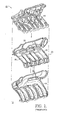
- a conventional intake manifold 10 for an internal combustion engine 12 is injection molded in three separate shells: upper shell 14, middle shell 16, and lower shell 18.
- the three shells are assembled together to form manifold 10 as by welding or adhesives.
- the process of molding and assembling manifold 10 is largely as disclosed in the incorporated US Patent No. 6,679,215 B2 .
- septum 20 between upper shell 14 and lower shell 18, which septum may be integral with any of shells 14,16,18 or may be formed as an additional element.
- septum 20 is formed as an integral component of middle shell 16, as shown in FIG. 1 .
- the shells and septum are typically molded of a heat-resistant fiber-filled polymer composite, such as glass-filled nylon or glass-filled polyphthalamide.
- a heat-resistant fiber-filled polymer composite such as glass-filled nylon or glass-filled polyphthalamide.
- the thickness of septum 20 is limited to about 4 mm to avoid excessive shrinkage and distortion of the polymer composite; however, as noted above, a thicker septum is desirable, both for enhanced rigidity and noise suppression.
- an improved septum 120 can be made significantly thicker than in the prior art if portions of the thicker septum are hollowed out, also known as being "cored" out, in molding.
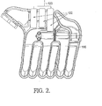
- one or more lenticular slides 122 are inserted into a mold (not shown) for a thicker septum 120 which preferably is a component of an improved middle shell 116. Three such slides 122 are shown in FIG. 2 When the mold is filled with liquid polymer composite, the slides 122 displace composite in designated regions of the mold.
- the slides are withdrawn 123 from the molded septum 120, resulting in a region of the septum having a structure comprising parallel plates 124a,124b separated by lenticular voids 126 (see FIG. 6 ).
- Plates 124a,124b are spaced apart in a first direction and are connected by ribs 128 separating voids 126 and spaced apart in a second direction.
- plates 124a,124b are each about 3 mm thick, and voids 126 are about 2.5 mm high and about 30 mm wide. Greater thicknesses of plates and voids are possible within the scope of the invention.
- the result is an I-beam type structure having an overall thickness of about 8.5 mm, which is relatively light, strong, rigid, and less prone to transmission of noise than the prior art solid septum 20.
- a currently preferred septum 120 for an intake manifold for the six-cylinder engine 12 shown in FIG. 1 is formed with six lenticular voids 126 extending varying distances into the septum. It is important that the voids open on the outside of the manifold, where the slides have been withdrawn, and not extend into the gas or fuel flow paths within the manifold. The voids should remain open in use to avoid captive air spaces which can subject the manifold to unwanted mechanical stresses during thermal changes.
- Ribs 128 are shown exemplarily as being formed substantially orthogonal to plates 124a,124b; however, it will be recognized that the ribs may be formed at non-normal angles (not shown) to the plates, like trusses, if so desired by appropriate modification of the cross-sectional shape of slides 122.
Landscapes
- Engineering & Computer Science (AREA)
- Chemical & Material Sciences (AREA)
- Combustion & Propulsion (AREA)
- Mechanical Engineering (AREA)
- General Engineering & Computer Science (AREA)
- Manufacturing & Machinery (AREA)
- Injection Moulding Of Plastics Or The Like (AREA)
- Moulds For Moulding Plastics Or The Like (AREA)
Abstract
In a method for forming an injection molded manifold, the portion of the mold that forms a septum is modified to provide a substantially thicker septum, preferably about 8.5 mm or greater. In the molding operation, one or more removable slides are inserted through this region of the mold, each slide being preferably about 2.5 mm thick and about 30 mm wide. The septum is cast around the slides which are then withdrawn from the septum after the polymer composite is set, resulting in a septum that is substantially thicker than a prior art septum, comprising first and second plates, each about 3 mm thick, and a plurality of open core voids about 2.5 mm high and about 30 mm wide between the plates. The improved septum is stiffer than a single 4 mm thick prior art septum, has a higher natural frequency, and improves suppression of engine noise.
Description
- The present invention relates to manifolds for internal combustion engines; more particularly, to manifolds formed by injection molding of polymer composites; and most particularly, to method and apparatus for forming a molded manifold section by coring out a thickened septum thereof to provide a stronger, less-resonant thicker remaining septum.
- Distribution manifolds for internal combustion engines are well known, especially intake manifolds for distribution of air to the combustion cylinders of an engine. In the older prior art, such manifolds were formed of metal, typically by die casting or "lost mold" casting. Aluminum manifolds are well known and are desirable for being lighter than comparable cast iron manifolds. Aluminum manifolds, however, are excellent transmitters of engine noise and are expensive to manufacture.
- In more recent prior art, manifolds are typically formed by injection molding of polymer composites in a plurality of separate sections, followed by joining of the sections by welding such as friction welding. See, for example,
US Patent No. 6,679,215 , the relevant disclosure of which is herein incorporated by reference. Exemplary polymer composites for use in forming intake manifolds are glass-filled nylon and glass-filled polyphthalamide. Such polymer composite manifolds transmit much less engine noise, are at least as light as aluminum manifolds, and are less expensive to manufacture. - A drawback of polymer composite manifolds manufactured by prior art methods and apparatus is that the wall thickness is limited to about 4 mm, although thicker walls are desirable in some regions of a manifold to reduce transmission of engine vibration and to raise the harmonic frequency of the walls. In modern tuned manifolds, there is typically a septum between two plenums directed to odd and even numbered cylinders, respectively. This septum is typically a flat planar element susceptible to vibration. Attempts to increase the septum thickness above about 4 mm have created increased process cycle times, and have resulted in increased warpage, increased shrinkage, and unacceptable overall dimensional changes in the molded components.
- What is needed in the art is means for increasing the effective thickness of a manifold plenum septum without causing unacceptable dimensional changes.
- It is a principal object of the present invention to provide an improved manifold having reduced propensity for vibration and noise transmission.
- Briefly described, in a method in accordance with the invention for forming an injection molded manifold, the portion of the mold that forms a septum is modified to produce a substantially thicker septum, preferably about 8.5 mm or greater. In the molding operation, one or more removable slides are inserted through this region of the mold, the slide being about 2.5 mm thick. The septum is cast around the slides which are then withdrawn from the region after the polymer composite is set, resulting in a septum that is preferably about 8.5 mm thick comprising parallel plates each about 3 mm thick and a plurality of open core voids about 2.5 mm high and about 30 mm wide. The improved septum is stiffer than a single 4 mm thick prior art septum and has a higher natural frequency.
- The present invention will now be described, by way of example, with reference to the accompanying drawings, in which:
-
FIG. 1 is an exploded isometric view of a prior art three-part injection-molded intake manifold for an in-line six-cylinder engine; -
FIG. 2 is a plan view of the underside of the center manifold shell shown inFIG. 1 , showing where three slides may be inserted into an improved integral septum (the septum itself is omitted from the drawing, for clarity); -
FIG. 3 is a schematic cross-sectional view taken through a portion of an improved cored septum in accordance with the invention, showing the exemplary dimensions of the cored openings, ribs, and plates; -
FIG. 4 is a cross-sectional view of a cored manifold septum formed by coring with six different slides; -
FIG. 5 is an elevational view of the septum shown inFIG. 4 ; and -
FIG. 6 is an isometric view from below of a portion of the septum shown inFIG. 4 showing cored openings and ribs in the septum. - Corresponding reference characters indicate corresponding parts throughout the several views. The exemplification set out herein illustrates one preferred embodiment of the invention, in one form, and such exemplification is not to be construed as limiting the scope of the invention in any manner.
- Referring to
FIG. 1 , aconventional intake manifold 10 for aninternal combustion engine 12 is injection molded in three separate shells:upper shell 14,middle shell 16, andlower shell 18. The three shells are assembled together to formmanifold 10 as by welding or adhesives. The process of molding and assemblingmanifold 10 is largely as disclosed in the incorporatedUS Patent No. 6,679,215 B2 . - The novelty disclosed herein, which is the subject of the present invention, is an improvement in the formation of a
septum 20 betweenupper shell 14 andlower shell 18, which septum may be integral with any ofshells septum 20 is formed as an integral component ofmiddle shell 16, as shown inFIG. 1 . - The shells and septum are typically molded of a heat-resistant fiber-filled polymer composite, such as glass-filled nylon or glass-filled polyphthalamide. In the prior art, the thickness of
septum 20 is limited to about 4 mm to avoid excessive shrinkage and distortion of the polymer composite; however, as noted above, a thicker septum is desirable, both for enhanced rigidity and noise suppression. - Referring to
FIGS. 2 and3 , it has been found that an improvedseptum 120 can be made significantly thicker than in the prior art if portions of the thicker septum are hollowed out, also known as being "cored" out, in molding. Specifically, one or morelenticular slides 122 are inserted into a mold (not shown) for athicker septum 120 which preferably is a component of an improvedmiddle shell 116. Threesuch slides 122 are shown inFIG. 2 When the mold is filled with liquid polymer composite, theslides 122 displace composite in designated regions of the mold. After the composite material is set, the slides are withdrawn 123 from themolded septum 120, resulting in a region of the septum having a structure comprisingparallel plates FIG. 6 ).Plates ribs 128 separatingvoids 126 and spaced apart in a second direction. In a presently preferred embodiment, as shown inFIG. 3 ,plates voids 126 are about 2.5 mm high and about 30 mm wide. Greater thicknesses of plates and voids are possible within the scope of the invention. The result is an I-beam type structure having an overall thickness of about 8.5 mm, which is relatively light, strong, rigid, and less prone to transmission of noise than the priorart solid septum 20. - Referring to
FIGS. 4 through 6 , a currently preferredseptum 120 for an intake manifold for the six-cylinder engine 12 shown inFIG. 1 is formed with sixlenticular voids 126 extending varying distances into the septum. It is important that the voids open on the outside of the manifold, where the slides have been withdrawn, and not extend into the gas or fuel flow paths within the manifold. The voids should remain open in use to avoid captive air spaces which can subject the manifold to unwanted mechanical stresses during thermal changes. -
Ribs 128 are shown exemplarily as being formed substantially orthogonal toplates slides 122. - While the invention has been described by reference to various specific embodiments, it should be understood that numerous changes may be made within the spirit and scope of the inventive concepts described. Accordingly, it is intended that the invention not be limited to the described embodiments, but will have full scope defined by the language of the following claims.
Claims (8)
- A manifold for an internal combustion engine including a region formed of first and second plates spaced apart in a first direction and connected at intervals by a plurality of ribs spaced apart in a second direction to define a plurality of voids between said plates and said ribs in said region of said manifold.
- A manifold in accordance with Claim 1 wherein said manifold is an air intake manifold.
- A manifold in accordance with Claim 1 wherein said region is included in a septum for separating flow paths within said manifold.
- A manifold in accordance with Claim 1 wherein said manifold is formed by injection molding.
- A manifold in accordance with Claim 1 wherein said manifold is formed of a polymer composite material.
- A manifold in accordance with Claim 5 wherein said polymer composite material is selected from the group consisting of glass-filled nylon and glass-filled polyphthalamide.
- A manifold in accordance with Claim 1 wherein said ribs are formed orthogonal to said plates.
- In a manifold for an internal combustion engine said manifold including a region formed of first and second spaced apart plates and connected at intervals by a plurality of spaced apart ribs to define a plurality of voids between said plates and said ribs in a region of said manifold, a method for forming said manifold comprising the steps of:a) providing at least one slide for insertion into a manifold mold prior to entry of molten material for forming said region of said manifold;b) injecting said molten material into said mold around said slide;c) causing said material to become rigid; andd) withdrawing said slide from said rigid material to form at least one of said plurality of voids in said manifold region.
Applications Claiming Priority (1)
| Application Number | Priority Date | Filing Date | Title |
|---|---|---|---|
| US11/636,921 US7556007B2 (en) | 2006-12-11 | 2006-12-11 | Method and apparatus for forming a septum for an engine intake manifold |
Publications (1)
| Publication Number | Publication Date |
|---|---|
| EP1953380A2 true EP1953380A2 (en) | 2008-08-06 |
Family
ID=39032234
Family Applications (1)
| Application Number | Title | Priority Date | Filing Date |
|---|---|---|---|
| EP07121157A Withdrawn EP1953380A2 (en) | 2006-12-11 | 2007-11-20 | Method and Apparatus for Forming a Septum for an Engine Intake Manifold |
Country Status (2)
| Country | Link |
|---|---|
| US (1) | US7556007B2 (en) |
| EP (1) | EP1953380A2 (en) |
Families Citing this family (4)
| Publication number | Priority date | Publication date | Assignee | Title |
|---|---|---|---|---|
| US8550049B2 (en) * | 2009-06-26 | 2013-10-08 | Ford Global Technologies, Llc | Cover with integrated braces |
| US20110169186A1 (en) * | 2010-01-11 | 2011-07-14 | Brenda Bruman | Method for Producing Three Separate and Distinct Intake Manifolds from a Single Intake Manifold Casting For Three Different Multi-Cylinder Internal Combustion Engine Applications |
| JP5883304B2 (en) * | 2012-02-07 | 2016-03-15 | 株式会社Roki | Intake manifold |
| US10808657B2 (en) * | 2018-02-02 | 2020-10-20 | Ford Global Technologies, Llc | Vehicle component with an accessory mounting feature and a method and tool for forming |
Family Cites Families (2)
| Publication number | Priority date | Publication date | Assignee | Title |
|---|---|---|---|---|
| US6679215B2 (en) | 2001-11-30 | 2004-01-20 | Delphi Technologies, Inc. | Injection-molded air intake manifold for a V-style engine |
| US7082915B2 (en) * | 2003-04-07 | 2006-08-01 | Aisan Kogyo Kabushiki Kaisha | Resin intake manifold |
-
2006
- 2006-12-11 US US11/636,921 patent/US7556007B2/en active Active
-
2007
- 2007-11-20 EP EP07121157A patent/EP1953380A2/en not_active Withdrawn
Also Published As
| Publication number | Publication date |
|---|---|
| US7556007B2 (en) | 2009-07-07 |
| US20080135011A1 (en) | 2008-06-12 |
Similar Documents
| Publication | Publication Date | Title |
|---|---|---|
| JP5563726B1 (en) | Gravity mold | |
| US9057346B2 (en) | Intake manifold | |
| US7581522B2 (en) | Resin intake manifold | |
| JP2006241992A (en) | Intake manifold | |
| EP1953380A2 (en) | Method and Apparatus for Forming a Septum for an Engine Intake Manifold | |
| JPS62148055A (en) | Foam original model for engine-cylinder-block | |
| US10294886B2 (en) | Water jacket structure of cylinder head | |
| US20170356405A1 (en) | Intake manifold | |
| US7225786B2 (en) | Oil drain passage structure of cylinder block and core structure thereof | |
| JP2011122478A (en) | Cylinder head cover structure of internal combustion engine | |
| JP2013249822A (en) | Intake manifold | |
| US7814877B2 (en) | Intake manifold with reinforcing partitions | |
| JP6013085B2 (en) | Resin intake manifold | |
| JP4866387B2 (en) | Manufacturing method of resin intake manifold | |
| US11795894B1 (en) | Engine intake system | |
| WO2006009911A3 (en) | Polymeric manifold assembly and method | |
| JP5828705B2 (en) | Resin intake manifold | |
| EP1672210B1 (en) | Resin molded component | |
| JP2011127448A (en) | Method of manufacturing cylinder for engine, die of cylinder for engine and cylinder for engine | |
| JP4422878B2 (en) | Hollow part and manufacturing method thereof | |
| KR20200032451A (en) | Prefabricated Mold and Manufacturing Method Of Double Manifold Using The Same | |
| JP5782728B2 (en) | Intake structure of internal combustion engine | |
| JP3337305B2 (en) | Engine intake device and its core structure | |
| JP5060414B2 (en) | Closed deck type cylinder block and manufacturing method thereof | |
| JP2004100707A (en) | Resin intake manifold |
Legal Events
| Date | Code | Title | Description |
|---|---|---|---|
| PUAI | Public reference made under article 153(3) epc to a published international application that has entered the european phase |
Free format text: ORIGINAL CODE: 0009012 |
|
| AK | Designated contracting states |
Kind code of ref document: A2 Designated state(s): AT BE BG CH CY CZ DE DK EE ES FI FR GB GR HU IE IS IT LI LT LU LV MC MT NL PL PT RO SE SI SK TR |
|
| AX | Request for extension of the european patent |
Extension state: AL BA HR MK RS |
|
| STAA | Information on the status of an ep patent application or granted ep patent |
Free format text: STATUS: THE APPLICATION IS DEEMED TO BE WITHDRAWN |
|
| 18D | Application deemed to be withdrawn |
Effective date: 20100601 |