EP1953269A1 - Improved alumina coated grade - Google Patents
Improved alumina coated grade Download PDFInfo
- Publication number
- EP1953269A1 EP1953269A1 EP08101044A EP08101044A EP1953269A1 EP 1953269 A1 EP1953269 A1 EP 1953269A1 EP 08101044 A EP08101044 A EP 08101044A EP 08101044 A EP08101044 A EP 08101044A EP 1953269 A1 EP1953269 A1 EP 1953269A1
- Authority
- EP
- European Patent Office
- Prior art keywords
- layer
- hkl
- coating
- cemented carbide
- mtcvd
- Prior art date
- Legal status (The legal status is an assumption and is not a legal conclusion. Google has not performed a legal analysis and makes no representation as to the accuracy of the status listed.)
- Ceased
Links
- PNEYBMLMFCGWSK-UHFFFAOYSA-N aluminium oxide Inorganic materials [O-2].[O-2].[O-2].[Al+3].[Al+3] PNEYBMLMFCGWSK-UHFFFAOYSA-N 0.000 title abstract description 18
- 229910052594 sapphire Inorganic materials 0.000 claims abstract description 24
- 229910052757 nitrogen Inorganic materials 0.000 claims abstract description 23
- 238000005520 cutting process Methods 0.000 claims abstract description 18
- 239000011230 binding agent Substances 0.000 claims abstract description 17
- 238000000576 coating method Methods 0.000 claims description 37
- 239000011248 coating agent Substances 0.000 claims description 32
- 239000000758 substrate Substances 0.000 claims description 8
- 229910052758 niobium Inorganic materials 0.000 claims description 7
- 229910052715 tantalum Inorganic materials 0.000 claims description 5
- 229910052719 titanium Inorganic materials 0.000 claims description 5
- ATJFFYVFTNAWJD-UHFFFAOYSA-N Tin Chemical compound [Sn] ATJFFYVFTNAWJD-UHFFFAOYSA-N 0.000 claims description 4
- 229910052751 metal Inorganic materials 0.000 claims description 4
- 239000002184 metal Substances 0.000 claims description 4
- 150000001247 metal acetylides Chemical class 0.000 claims description 4
- 229910052760 oxygen Inorganic materials 0.000 claims description 4
- 150000002739 metals Chemical class 0.000 claims description 3
- 230000000737 periodic effect Effects 0.000 claims description 3
- VSCWAEJMTAWNJL-UHFFFAOYSA-K aluminium trichloride Chemical compound Cl[Al](Cl)Cl VSCWAEJMTAWNJL-UHFFFAOYSA-K 0.000 description 16
- 239000000203 mixture Substances 0.000 description 16
- 238000000034 method Methods 0.000 description 14
- IJGRMHOSHXDMSA-UHFFFAOYSA-N Atomic nitrogen Chemical compound N#N IJGRMHOSHXDMSA-UHFFFAOYSA-N 0.000 description 13
- 239000007789 gas Substances 0.000 description 11
- 230000006911 nucleation Effects 0.000 description 9
- 238000010899 nucleation Methods 0.000 description 9
- 238000000151 deposition Methods 0.000 description 8
- 238000010926 purge Methods 0.000 description 8
- 239000000843 powder Substances 0.000 description 7
- 238000005245 sintering Methods 0.000 description 7
- 229910052799 carbon Inorganic materials 0.000 description 6
- 239000000463 material Substances 0.000 description 6
- 229910052721 tungsten Inorganic materials 0.000 description 6
- WEVYAHXRMPXWCK-UHFFFAOYSA-N Acetonitrile Chemical compound CC#N WEVYAHXRMPXWCK-UHFFFAOYSA-N 0.000 description 5
- 229910003074 TiCl4 Inorganic materials 0.000 description 5
- 230000008021 deposition Effects 0.000 description 5
- XJDNKRIXUMDJCW-UHFFFAOYSA-J titanium tetrachloride Chemical compound Cl[Ti](Cl)(Cl)Cl XJDNKRIXUMDJCW-UHFFFAOYSA-J 0.000 description 5
- WFKWXMTUELFFGS-UHFFFAOYSA-N tungsten Chemical compound [W] WFKWXMTUELFFGS-UHFFFAOYSA-N 0.000 description 5
- 239000010937 tungsten Substances 0.000 description 5
- 230000003647 oxidation Effects 0.000 description 4
- 238000007254 oxidation reaction Methods 0.000 description 4
- OKTJSMMVPCPJKN-UHFFFAOYSA-N Carbon Chemical compound [C] OKTJSMMVPCPJKN-UHFFFAOYSA-N 0.000 description 3
- 239000002826 coolant Substances 0.000 description 3
- 229910001018 Cast iron Inorganic materials 0.000 description 2
- 238000002441 X-ray diffraction Methods 0.000 description 2
- 229910002091 carbon monoxide Inorganic materials 0.000 description 2
- 239000003795 chemical substances by application Substances 0.000 description 2
- 229910017052 cobalt Inorganic materials 0.000 description 2
- 239000010941 cobalt Substances 0.000 description 2
- GUTLYIVDDKVIGB-UHFFFAOYSA-N cobalt atom Chemical compound [Co] GUTLYIVDDKVIGB-UHFFFAOYSA-N 0.000 description 2
- 238000001816 cooling Methods 0.000 description 2
- 238000003825 pressing Methods 0.000 description 2
- 229910018072 Al 2 O 3 Inorganic materials 0.000 description 1
- UFHFLCQGNIYNRP-UHFFFAOYSA-N Hydrogen Chemical compound [H][H] UFHFLCQGNIYNRP-UHFFFAOYSA-N 0.000 description 1
- 229910007932 ZrCl4 Inorganic materials 0.000 description 1
- OFHCOWSQAMBJIW-AVJTYSNKSA-N alfacalcidol Chemical compound C1(/[C@@H]2CC[C@@H]([C@]2(CCC1)C)[C@H](C)CCCC(C)C)=C\C=C1\C[C@@H](O)C[C@H](O)C1=C OFHCOWSQAMBJIW-AVJTYSNKSA-N 0.000 description 1
- QVGXLLKOCUKJST-UHFFFAOYSA-N atomic oxygen Chemical compound [O] QVGXLLKOCUKJST-UHFFFAOYSA-N 0.000 description 1
- 230000015572 biosynthetic process Effects 0.000 description 1
- 230000002301 combined effect Effects 0.000 description 1
- 238000004320 controlled atmosphere Methods 0.000 description 1
- 229910052593 corundum Inorganic materials 0.000 description 1
- 230000003247 decreasing effect Effects 0.000 description 1
- 230000007547 defect Effects 0.000 description 1
- 238000005137 deposition process Methods 0.000 description 1
- 238000013461 design Methods 0.000 description 1
- 229910001873 dinitrogen Inorganic materials 0.000 description 1
- 238000004090 dissolution Methods 0.000 description 1
- 239000001257 hydrogen Substances 0.000 description 1
- 229910052739 hydrogen Inorganic materials 0.000 description 1
- 238000011065 in-situ storage Methods 0.000 description 1
- 238000011835 investigation Methods 0.000 description 1
- 238000003754 machining Methods 0.000 description 1
- 238000003801 milling Methods 0.000 description 1
- 238000012986 modification Methods 0.000 description 1
- 230000004048 modification Effects 0.000 description 1
- 150000004767 nitrides Chemical class 0.000 description 1
- 238000005121 nitriding Methods 0.000 description 1
- 239000001301 oxygen Substances 0.000 description 1
- 239000002243 precursor Substances 0.000 description 1
- 230000005855 radiation Effects 0.000 description 1
- 239000002994 raw material Substances 0.000 description 1
- 239000000376 reactant Substances 0.000 description 1
- 229920006395 saturated elastomer Polymers 0.000 description 1
- 238000001878 scanning electron micrograph Methods 0.000 description 1
- 238000012163 sequencing technique Methods 0.000 description 1
- 239000007921 spray Substances 0.000 description 1
- 229910001220 stainless steel Inorganic materials 0.000 description 1
- 239000010935 stainless steel Substances 0.000 description 1
- 230000035882 stress Effects 0.000 description 1
- 230000003746 surface roughness Effects 0.000 description 1
- 238000012360 testing method Methods 0.000 description 1
- 230000008646 thermal stress Effects 0.000 description 1
- 230000009466 transformation Effects 0.000 description 1
- 229910001845 yogo sapphire Inorganic materials 0.000 description 1
- DUNKXUFBGCUVQW-UHFFFAOYSA-J zirconium tetrachloride Chemical compound Cl[Zr](Cl)(Cl)Cl DUNKXUFBGCUVQW-UHFFFAOYSA-J 0.000 description 1
Images
Classifications
-
- B—PERFORMING OPERATIONS; TRANSPORTING
- B23—MACHINE TOOLS; METAL-WORKING NOT OTHERWISE PROVIDED FOR
- B23B—TURNING; BORING
- B23B27/00—Tools for turning or boring machines; Tools of a similar kind in general; Accessories therefor
- B23B27/14—Cutting tools of which the bits or tips or cutting inserts are of special material
- B23B27/148—Composition of the cutting inserts
-
- C—CHEMISTRY; METALLURGY
- C23—COATING METALLIC MATERIAL; COATING MATERIAL WITH METALLIC MATERIAL; CHEMICAL SURFACE TREATMENT; DIFFUSION TREATMENT OF METALLIC MATERIAL; COATING BY VACUUM EVAPORATION, BY SPUTTERING, BY ION IMPLANTATION OR BY CHEMICAL VAPOUR DEPOSITION, IN GENERAL; INHIBITING CORROSION OF METALLIC MATERIAL OR INCRUSTATION IN GENERAL
- C23C—COATING METALLIC MATERIAL; COATING MATERIAL WITH METALLIC MATERIAL; SURFACE TREATMENT OF METALLIC MATERIAL BY DIFFUSION INTO THE SURFACE, BY CHEMICAL CONVERSION OR SUBSTITUTION; COATING BY VACUUM EVAPORATION, BY SPUTTERING, BY ION IMPLANTATION OR BY CHEMICAL VAPOUR DEPOSITION, IN GENERAL
- C23C16/00—Chemical coating by decomposition of gaseous compounds, without leaving reaction products of surface material in the coating, i.e. chemical vapour deposition [CVD] processes
-
- C—CHEMISTRY; METALLURGY
- C23—COATING METALLIC MATERIAL; COATING MATERIAL WITH METALLIC MATERIAL; CHEMICAL SURFACE TREATMENT; DIFFUSION TREATMENT OF METALLIC MATERIAL; COATING BY VACUUM EVAPORATION, BY SPUTTERING, BY ION IMPLANTATION OR BY CHEMICAL VAPOUR DEPOSITION, IN GENERAL; INHIBITING CORROSION OF METALLIC MATERIAL OR INCRUSTATION IN GENERAL
- C23C—COATING METALLIC MATERIAL; COATING MATERIAL WITH METALLIC MATERIAL; SURFACE TREATMENT OF METALLIC MATERIAL BY DIFFUSION INTO THE SURFACE, BY CHEMICAL CONVERSION OR SUBSTITUTION; COATING BY VACUUM EVAPORATION, BY SPUTTERING, BY ION IMPLANTATION OR BY CHEMICAL VAPOUR DEPOSITION, IN GENERAL
- C23C16/00—Chemical coating by decomposition of gaseous compounds, without leaving reaction products of surface material in the coating, i.e. chemical vapour deposition [CVD] processes
- C23C16/02—Pretreatment of the material to be coated
- C23C16/0272—Deposition of sub-layers, e.g. to promote the adhesion of the main coating
-
- C—CHEMISTRY; METALLURGY
- C23—COATING METALLIC MATERIAL; COATING MATERIAL WITH METALLIC MATERIAL; CHEMICAL SURFACE TREATMENT; DIFFUSION TREATMENT OF METALLIC MATERIAL; COATING BY VACUUM EVAPORATION, BY SPUTTERING, BY ION IMPLANTATION OR BY CHEMICAL VAPOUR DEPOSITION, IN GENERAL; INHIBITING CORROSION OF METALLIC MATERIAL OR INCRUSTATION IN GENERAL
- C23C—COATING METALLIC MATERIAL; COATING MATERIAL WITH METALLIC MATERIAL; SURFACE TREATMENT OF METALLIC MATERIAL BY DIFFUSION INTO THE SURFACE, BY CHEMICAL CONVERSION OR SUBSTITUTION; COATING BY VACUUM EVAPORATION, BY SPUTTERING, BY ION IMPLANTATION OR BY CHEMICAL VAPOUR DEPOSITION, IN GENERAL
- C23C16/00—Chemical coating by decomposition of gaseous compounds, without leaving reaction products of surface material in the coating, i.e. chemical vapour deposition [CVD] processes
- C23C16/22—Chemical coating by decomposition of gaseous compounds, without leaving reaction products of surface material in the coating, i.e. chemical vapour deposition [CVD] processes characterised by the deposition of inorganic material, other than metallic material
- C23C16/30—Deposition of compounds, mixtures or solid solutions, e.g. borides, carbides, nitrides
-
- C—CHEMISTRY; METALLURGY
- C23—COATING METALLIC MATERIAL; COATING MATERIAL WITH METALLIC MATERIAL; CHEMICAL SURFACE TREATMENT; DIFFUSION TREATMENT OF METALLIC MATERIAL; COATING BY VACUUM EVAPORATION, BY SPUTTERING, BY ION IMPLANTATION OR BY CHEMICAL VAPOUR DEPOSITION, IN GENERAL; INHIBITING CORROSION OF METALLIC MATERIAL OR INCRUSTATION IN GENERAL
- C23C—COATING METALLIC MATERIAL; COATING MATERIAL WITH METALLIC MATERIAL; SURFACE TREATMENT OF METALLIC MATERIAL BY DIFFUSION INTO THE SURFACE, BY CHEMICAL CONVERSION OR SUBSTITUTION; COATING BY VACUUM EVAPORATION, BY SPUTTERING, BY ION IMPLANTATION OR BY CHEMICAL VAPOUR DEPOSITION, IN GENERAL
- C23C16/00—Chemical coating by decomposition of gaseous compounds, without leaving reaction products of surface material in the coating, i.e. chemical vapour deposition [CVD] processes
- C23C16/22—Chemical coating by decomposition of gaseous compounds, without leaving reaction products of surface material in the coating, i.e. chemical vapour deposition [CVD] processes characterised by the deposition of inorganic material, other than metallic material
- C23C16/30—Deposition of compounds, mixtures or solid solutions, e.g. borides, carbides, nitrides
- C23C16/40—Oxides
- C23C16/403—Oxides of aluminium, magnesium or beryllium
-
- C—CHEMISTRY; METALLURGY
- C23—COATING METALLIC MATERIAL; COATING MATERIAL WITH METALLIC MATERIAL; CHEMICAL SURFACE TREATMENT; DIFFUSION TREATMENT OF METALLIC MATERIAL; COATING BY VACUUM EVAPORATION, BY SPUTTERING, BY ION IMPLANTATION OR BY CHEMICAL VAPOUR DEPOSITION, IN GENERAL; INHIBITING CORROSION OF METALLIC MATERIAL OR INCRUSTATION IN GENERAL
- C23C—COATING METALLIC MATERIAL; COATING MATERIAL WITH METALLIC MATERIAL; SURFACE TREATMENT OF METALLIC MATERIAL BY DIFFUSION INTO THE SURFACE, BY CHEMICAL CONVERSION OR SUBSTITUTION; COATING BY VACUUM EVAPORATION, BY SPUTTERING, BY ION IMPLANTATION OR BY CHEMICAL VAPOUR DEPOSITION, IN GENERAL
- C23C16/00—Chemical coating by decomposition of gaseous compounds, without leaving reaction products of surface material in the coating, i.e. chemical vapour deposition [CVD] processes
- C23C16/44—Chemical coating by decomposition of gaseous compounds, without leaving reaction products of surface material in the coating, i.e. chemical vapour deposition [CVD] processes characterised by the method of coating
- C23C16/455—Chemical coating by decomposition of gaseous compounds, without leaving reaction products of surface material in the coating, i.e. chemical vapour deposition [CVD] processes characterised by the method of coating characterised by the method used for introducing gases into reaction chamber or for modifying gas flows in reaction chamber
- C23C16/45523—Pulsed gas flow or change of composition over time
-
- C—CHEMISTRY; METALLURGY
- C23—COATING METALLIC MATERIAL; COATING MATERIAL WITH METALLIC MATERIAL; CHEMICAL SURFACE TREATMENT; DIFFUSION TREATMENT OF METALLIC MATERIAL; COATING BY VACUUM EVAPORATION, BY SPUTTERING, BY ION IMPLANTATION OR BY CHEMICAL VAPOUR DEPOSITION, IN GENERAL; INHIBITING CORROSION OF METALLIC MATERIAL OR INCRUSTATION IN GENERAL
- C23C—COATING METALLIC MATERIAL; COATING MATERIAL WITH METALLIC MATERIAL; SURFACE TREATMENT OF METALLIC MATERIAL BY DIFFUSION INTO THE SURFACE, BY CHEMICAL CONVERSION OR SUBSTITUTION; COATING BY VACUUM EVAPORATION, BY SPUTTERING, BY ION IMPLANTATION OR BY CHEMICAL VAPOUR DEPOSITION, IN GENERAL
- C23C30/00—Coating with metallic material characterised only by the composition of the metallic material, i.e. not characterised by the coating process
- C23C30/005—Coating with metallic material characterised only by the composition of the metallic material, i.e. not characterised by the coating process on hard metal substrates
-
- Y—GENERAL TAGGING OF NEW TECHNOLOGICAL DEVELOPMENTS; GENERAL TAGGING OF CROSS-SECTIONAL TECHNOLOGIES SPANNING OVER SEVERAL SECTIONS OF THE IPC; TECHNICAL SUBJECTS COVERED BY FORMER USPC CROSS-REFERENCE ART COLLECTIONS [XRACs] AND DIGESTS
- Y10—TECHNICAL SUBJECTS COVERED BY FORMER USPC
- Y10T—TECHNICAL SUBJECTS COVERED BY FORMER US CLASSIFICATION
- Y10T428/00—Stock material or miscellaneous articles
- Y10T428/12—All metal or with adjacent metals
- Y10T428/12493—Composite; i.e., plural, adjacent, spatially distinct metal components [e.g., layers, joint, etc.]
- Y10T428/12535—Composite; i.e., plural, adjacent, spatially distinct metal components [e.g., layers, joint, etc.] with additional, spatially distinct nonmetal component
- Y10T428/12576—Boride, carbide or nitride component
-
- Y—GENERAL TAGGING OF NEW TECHNOLOGICAL DEVELOPMENTS; GENERAL TAGGING OF CROSS-SECTIONAL TECHNOLOGIES SPANNING OVER SEVERAL SECTIONS OF THE IPC; TECHNICAL SUBJECTS COVERED BY FORMER USPC CROSS-REFERENCE ART COLLECTIONS [XRACs] AND DIGESTS
- Y10—TECHNICAL SUBJECTS COVERED BY FORMER USPC
- Y10T—TECHNICAL SUBJECTS COVERED BY FORMER US CLASSIFICATION
- Y10T428/00—Stock material or miscellaneous articles
- Y10T428/24—Structurally defined web or sheet [e.g., overall dimension, etc.]
- Y10T428/24942—Structurally defined web or sheet [e.g., overall dimension, etc.] including components having same physical characteristic in differing degree
- Y10T428/2495—Thickness [relative or absolute]
- Y10T428/24967—Absolute thicknesses specified
- Y10T428/24975—No layer or component greater than 5 mils thick
-
- Y—GENERAL TAGGING OF NEW TECHNOLOGICAL DEVELOPMENTS; GENERAL TAGGING OF CROSS-SECTIONAL TECHNOLOGIES SPANNING OVER SEVERAL SECTIONS OF THE IPC; TECHNICAL SUBJECTS COVERED BY FORMER USPC CROSS-REFERENCE ART COLLECTIONS [XRACs] AND DIGESTS
- Y10—TECHNICAL SUBJECTS COVERED BY FORMER USPC
- Y10T—TECHNICAL SUBJECTS COVERED BY FORMER US CLASSIFICATION
- Y10T428/00—Stock material or miscellaneous articles
- Y10T428/25—Web or sheet containing structurally defined element or component and including a second component containing structurally defined particles
- Y10T428/252—Glass or ceramic [i.e., fired or glazed clay, cement, etc.] [porcelain, quartz, etc.]
-
- Y—GENERAL TAGGING OF NEW TECHNOLOGICAL DEVELOPMENTS; GENERAL TAGGING OF CROSS-SECTIONAL TECHNOLOGIES SPANNING OVER SEVERAL SECTIONS OF THE IPC; TECHNICAL SUBJECTS COVERED BY FORMER USPC CROSS-REFERENCE ART COLLECTIONS [XRACs] AND DIGESTS
- Y10—TECHNICAL SUBJECTS COVERED BY FORMER USPC
- Y10T—TECHNICAL SUBJECTS COVERED BY FORMER US CLASSIFICATION
- Y10T428/00—Stock material or miscellaneous articles
- Y10T428/26—Web or sheet containing structurally defined element or component, the element or component having a specified physical dimension
- Y10T428/263—Coating layer not in excess of 5 mils thick or equivalent
- Y10T428/264—Up to 3 mils
- Y10T428/265—1 mil or less
Definitions
- the present invention relates to a coated cutting tool insert designed to be used in metal machining.
- the substrate is cemented carbide with a tough surface zone on which a hard and wear resistant coating is deposited.
- the coating exhibits an excellent adhesion to the substrate covering all functional parts thereof.
- the coating is composed of one or more refractory layers of which at least one layer is a strongly (104) textured alpha-alumina ( ⁇ -Al 2 O 3 ).
- US 7,011,867 describes a method to obtain a strong (300) texture in ⁇ -Al 2 O 3 using a texture modifying agent (ZrCl 4 ).
- the prior-art processes discussed above use all high deposition temperatures of about 1000 °C.
- US 7,094,447 describes a technique to achieve a pronounced (102) texture.
- Enhanced deposition techniques to produce pronounced (104) and (116) textures are disclosed in US 2006/0199026 and US 2006/0141271 , respectively.
- It is an object of the present invention is to provide an improved ⁇ -Al 2 O 3 coated cutting tool insert.
- the ⁇ -Al 2 O 3 phase according to the present invention consists of nucleated ⁇ -Al 2 O 3 with a strong, fully controlled (104) growth texture and is deposited on a binder phase enriched cemented carbide substrate.
- the ⁇ -Al 2 O 3 layer with the controlled (104) texture can be obtained within a temperature range from 750 to 1000 °C, which reduces the thermal stresses. This kind of alumina coated grade outperforms the prior art with random or other less developed textures. Further, increased toughness can be obtained when deposition is carried out at lower temperatures.
- the ⁇ -Al 2 O 3 layer according the present invention is essentially free from transformation stresses, consists of columnar, defect free, ⁇ -Al 2 O 3 grains with low dislocation density and has improved cutting properties. It was surprisingly noted that the (104) texture according to this invention outperforms the prior-art (012) texture by 30-60%. This surprising improvement can be explained by the combined effect of the (104) texture, Co-enrichment and enhanced bonding layer.
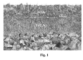
- Fig. 1 shows a fracture cross-section SEM image of a typical coating according to the present invention (magnification 10 000x).
- the alumina layer is composed of columnar grains with (104) texture.
- the coating is dense with no detectable porosity.
- a coated cutting tool insert consisting of a cemented carbide body with a composition of 5-9 wt-%, preferably 6-8 wt-%, most preferably 6.0-7.0 wt-% Co, and 5-11, preferably 6.5-9.5, wt-% cubic carbides of the metals from groups IVb, Vb and VIb of the periodic table, preferably Ti, Nb and Ta, and balance WC.
- the ratio between the weight concentrations of Ta and Nb is 1.0-3.0, preferably 1.5-2.5 and/or between the weight concentrations of Ti and Nb 0.5-1.5, preferably 0.8-1.2.
- the cobalt binder phase is highly alloyed with tungsten.
- the cemented carbide body has an S-value within the range 0.79-0.90, preferably 0.81-0.85.
- the mean grain size of the carbide phases may be expressed as the coercivity of the cemented carbide.
- the cemented carbide body is provided with a 5-40 ⁇ m thick, preferably 10-30 ⁇ m thick, most preferably 20-30 ⁇ m thick, essentially cubic carbide phase free and binder phase enriched surface zone with an average binder phase content in the range 1.2-2.5 times the nominal binder phase content.
- the invention also relates to methods of making cutting tool inserts according to the description comprising a cemented carbide substrate consisting of a binder phase of Co, WC and a cubic carbonitride phase with a binder phase enriched surface zone essentially free of cubic phase and a coating.
- a powder mixture containing 5-9, preferably 6-8 wt-%, most preferably 6.0-7.0 wt-% Co, and 5-11, preferably 6.5-9.5, wt-% cubic carbides of the metals from groups IVb, Vb and VIb of the periodic table, preferably Ti, Nb and Ta, and balance WC is prepared.
- the ratio between the weight concentrations of Ta and Nb is within 1.0-3.0, preferably 1.5-2.5 and/or between Ti and Nb within 0.5-1.5, preferably 0.8-1.2.
- Well-controlled amounts of nitrogen are added through the powder e.g. as nitrides or by performing an in-situ nitriding in the sintering furnace using e.g. nitrogen gas.
- the optimum amount of nitrogen to be added depends on the composition of the cemented carbide and in particular on the amount of cubic phases. The exact conditions depend to a certain extent on the design of the sintering equipment being used. It is within the purview of the skilled artisan to determine and to modify the nitrogen addition and the sintering process in accordance with the present specification in order to obtain the desired results.
- the powder mixture is further mixed with pressing agent. Tungsten or carbon is added to obtain the desired S-value and the mixture is milled and spray dried to obtain a powder material with the desired properties. Next, the powder material is compacted and sintered. Sintering is performed at a temperature of 1300-1500°C, in a controlled atmosphere of about 50 mbar followed by cooling.
- the coating comprises at least one alpha alumina layer composed of columnar grains with a strong (104) texture.
- the columnar grains have a length/width ratio of from 2 to 12, preferably 4 to 8.
- the thickness of the layer is from 2 to 9 ⁇ m, preferably from 5 to 7 ⁇ m.
- the texture of the alumina layer is defined as follows:
- TC(104) is ⁇ 2.0, preferably ⁇ 3.
- Simultaneously TC(012), TC(110) and TC(113) are all ⁇ 1.0, preferably ⁇ 0.5.
- TC(116) is somewhat higher than the other background reflections.
- TC(116) should be less than 1.2, preferably less than 1 but preferably >0.5.
- the surface thereof is preferably wet-blasted to a surface roughness Ra of ⁇ 1.0 ⁇ m, preferably ⁇ 0.7 ⁇ m.
- the coating comprises a MTCVD Ti(C,N) as the first layer adjacent the body having a thickness of from 2 to 10 ⁇ m, preferably from 4 to 6 ⁇ m.
- a MTCVD Ti(C,N) as the first layer adjacent the body having a thickness of from 2 to 10 ⁇ m, preferably from 4 to 6 ⁇ m.
- there is an additional TiN layer in the Ti(C,N) layer having a thickness of 0.5-3 ⁇ m, preferably 1.0-2.0 ⁇ m located 0.5-2.5 ⁇ m below the alumina layer.
- the first MTCVD Ti(C,N) layer adjacent the substrate can be substituted by CVD Ti(C,N), CVD TiN, CVD TiC, MTCVD Zr(C,N), MTCVD Ti(B,C,N), CVD HfN or combinations thereof.
- alumina layer Between the alumina layer and its closest underlying layer there is a (Ti,Al)(C,O,N) 0.1-1 ⁇ m thick bonding layer preferably with an Al concentration gradient.
- the present invention also relates to a refined method to produce textured ⁇ -Al 2 O 3 layers in a temperature range of 750-1000°C with a (104) texture.
- a bonding layer is deposited (1). Nitrogen and CH 3 CN are applied during deposition of this bonding layer. The surface of this bonding layer is subjected to an additional treatment(s).
- the oxidising step has to be relatively short, about 0.5-5 minutes to secure (104) nucleation. These steps should be repeated several times, preferably 2-5 times, in sequence to increase the amount of ⁇ -Al 2 O 3 nuclei.
- the key to obtain the specified growth texture is the control of the oxidation potential of the CO 2 /H 2 /N 2 /Ar mixture by adjustment of the N 2 :CO 2 ratio.
- This ratio should be 450-650, preferably 450-550.
- the use of controlled oxygen potential in combination with the correct time and number of pulses enables the correct nucleation mode. Typical pulse times may range from 10 seconds to 5 minutes depending on the duration of the pulse.
- the oxidising pulse is again followed by an Ar purge (6).
- the growth of the alumina layer onto the nucleation layer is started by sequencing the reactant gases in the following order: CO, AlCl 3 , CO 2 .
- the process temperatures of 750 to 950°C can be used since the texture is determined by the nucleation surface.
- Al 2 O 3 layers according to the present invention are especially suitable be used in toughness demanding stainless steel application such as interrupted turning, turning with coolant and especially intermittent turning with coolant.
- the other area is cast iron where the edge strength of this kind of alumina layer is superior to the prior art (012-texture).
- Cemented carbide inserts of type CNMG120408-M3, WNMG080416 and SNUN120408 comprising 6.6 wt% Co, 3,4 wt% TaC, 2.2 wt% NbC, 2,9 wt% (Ti,W)C 50/50 (H.C. Starck) and balance WC, with a binder phase alloyed with W corresponding to an S-value of 0.83 was produced according to the invention. Inserts were produced by conventional milling of the raw material powders, pressing of the green compacts and subsequent sintering at 1430°C. The nitrogen was added to the carbide powder as Ti(C,N). The micro structural investigation after sintering showed that an essentially cubic carbide free surface zone with a thickness of about 20 ⁇ m was formed. The coercivity was about 12.1 kA/m corresponding to an average grain size of about 1 ⁇ m.
- Cemented carbide cutting inserts from Example 1 were coated with a layer of Ti(C,N) with MTCVD-technique, using acetonitrile as the carbon and nitrogen source for forming the layer at a temperature of 860°C.
- the thickness of the MTCVD layer was about 6 ⁇ m.
- a layer of 5-6 ⁇ m ⁇ -Al 2 O 3 was deposited as follows:
- Steps 3-6 were repeated three times.
- the alumina layers in coatings a) and b) were studied using X-ray diffraction with CuK ⁇ -radiation. The texture coefficients were determined and are presented in Table 2. As clear from Table 3 the coating according to this invention exhibits a strong (104) texture when deposited either at 950°C. Typically, for this growth mode the (116) reflection is somewhat more pronounced than the other background reflections. The alumina layers were also studied in SEM. The alumina layers according to the invention exhibited a columnar morphology with a length/width ratio of 6, see Fig 1 . Table 2. hkl Invention, Coating a) Prior art, coating b) 012 0.15 4.49 104 3.76 0.05 110 0.06 0.20 113 0.19 0.17 116 0.84 0.09
- the coatings produced according to this invention were compared with a "Competitor X".
- This coating is composed of MTCVD Ti(C,N) and ⁇ -Al 2 O 3 .
- XRD was used to determine the texture coefficients for these competitor coatings.
- Two inserts from Competitor X were randomly chosen for XRD.
- Table 5 shows the obtained TCs for the insert according to the invention and for Competitor X.
- the coatings from Competitor X exhibited a quite random texture as compared with the present invention, Table 4.
- Table 4 Hkl TC(hkl), invention TC(hkl) competitor 012 0.19 1.52 1.50 104 3.79 0.92 0.94 110 0.06 1.07 1.12 113 0.12 0.47 0.33 116 0.84 1.02 1.11
- the inserts produced according to the present invention were further compared in interrupted cutting with a "Competitor X" in a face turning operation.
- Work piece Cylindrical bar with drilled holes.
- Material SS2258 Insert type: CNMG 120416-M3 Cutting speed: 200 m/min Feed: 0.4 mm/rev Depth of cut: 1.0 mm Remarks: Coolant
- Coating a) and b) were tested with respect to toughness in longitudinal turning with interrupted cuts.
- Work piece Cylindrical slotted bar Material: SS1672 Insert type: CNMG120408-M3 Cutting speed: 140 m/min Feed: 0.1, 0.125, 0.16, 0.20, 0.25, 0.315, 0.4, 0.5, 0.63, 0.8 mm/rev gradually increased after 10 mm length of cut Depth of cut: 2.5 mm
- Remarks dry turning Tool life criteria: Gradually increased feed until edge breakage. Ten edges of each variant were tested.
- the test results show (Table 6) that the coating according to the present invention (coating a) exhibits clearly better toughness behaviour than the prior-art (coating b).
- Table 6 Mean feed at breakage (mm/rev) Coating a (invention) 0.42 Coating b (prior art) 0.22
Landscapes
- Chemical & Material Sciences (AREA)
- Mechanical Engineering (AREA)
- Engineering & Computer Science (AREA)
- Organic Chemistry (AREA)
- Materials Engineering (AREA)
- Metallurgy (AREA)
- Chemical Kinetics & Catalysis (AREA)
- General Chemical & Material Sciences (AREA)
- Inorganic Chemistry (AREA)
- Chemical Vapour Deposition (AREA)
- Cutting Tools, Boring Holders, And Turrets (AREA)
- Crystals, And After-Treatments Of Crystals (AREA)
- Other Surface Treatments For Metallic Materials (AREA)
- Powder Metallurgy (AREA)
Abstract
Description
- The present invention relates to a coated cutting tool insert designed to be used in metal machining. The substrate is cemented carbide with a tough surface zone on which a hard and wear resistant coating is deposited. The coating exhibits an excellent adhesion to the substrate covering all functional parts thereof. The coating is composed of one or more refractory layers of which at least one layer is a strongly (104) textured alpha-alumina (α-Al2O3).
- The control of the α-Al2O3 polymorph in industrial scale was achieved in the beginning of the 1990's with commercial products based on
US patent 5,137,774 . Later modifications of this patent have been used to deposit α-Al2O3 with preferred textures. InUS 5,654,035 an alumina layer textured in the (012) direction, inUS 5,766,782 in the (104)-direction and inUS 5,980,988 in the (110) direction are disclosed. InUS 5,863,640 a preferred growth either along (012), or (104) or (110) is disclosed.US 6,333,103 describes a modified method to control the nucleation and growth of α-Al2O3 along the (10(10)) direction.US 7,011,867 describes a method to obtain a strong (300) texture in α-Al2O3 using a texture modifying agent (ZrCl4). The prior-art processes discussed above use all high deposition temperatures of about 1000 °C.US 7,094,447 describes a technique to achieve a pronounced (102) texture. Enhanced deposition techniques to produce pronounced (104) and (116) textures are disclosed inUS 2006/0199026 andUS 2006/0141271 , respectively. - Methods to produce a tough binder phase enriched zone in the upper part of a cemented carbide insert prior to coating are commonly referred to as gradient sintering. There are two types of processes, which are used to produce the binder phase enriched zone:
- (i) By dissolution of the cubic phase near the surface (N-gradient).
US 4,277,283 ,4,610,931 ,4,830,930 and5,106,674 . - (ii) By controlled cooling or decarburisation (C-gradient)
US 5,106,674 andUS 4,830,930 - It is an object of the present invention is to provide an improved α-Al2O3 coated cutting tool insert.
- The α-Al2O3 phase according to the present invention consists of nucleated α-Al2O3 with a strong, fully controlled (104) growth texture and is deposited on a binder phase enriched cemented carbide substrate. The α-Al2O3 layer with the controlled (104) texture can be obtained within a temperature range from 750 to 1000 °C, which reduces the thermal stresses. This kind of alumina coated grade outperforms the prior art with random or other less developed textures. Further, increased toughness can be obtained when deposition is carried out at lower temperatures. Compared with prior-art products the α-Al2O3 layer according the present invention is essentially free from transformation stresses, consists of columnar, defect free, α-Al2O3 grains with low dislocation density and has improved cutting properties. It was surprisingly noted that the (104) texture according to this invention outperforms the prior-art (012) texture by 30-60%. This surprising improvement can be explained by the combined effect of the (104) texture, Co-enrichment and enhanced bonding layer.
-
Fig. 1 shows a fracture cross-section SEM image of a typical coating according to the present invention (magnification 10 000x). The alumina layer is composed of columnar grains with (104) texture. The coating is dense with no detectable porosity. - According to the present invention a coated cutting tool insert is provided consisting of a cemented carbide body with a composition of 5-9 wt-%, preferably 6-8 wt-%, most preferably 6.0-7.0 wt-% Co, and 5-11, preferably 6.5-9.5, wt-% cubic carbides of the metals from groups IVb, Vb and VIb of the periodic table, preferably Ti, Nb and Ta, and balance WC. Preferably, the ratio between the weight concentrations of Ta and Nb is 1.0-3.0, preferably 1.5-2.5 and/or between the weight concentrations of Ti and Nb 0.5-1.5, preferably 0.8-1.2.
- The cobalt binder phase is highly alloyed with tungsten. The concentration of W in the binder phase may be expressed as the S-value = σ/16.1, where σ is the magnetic moment of the binder phase in µTm3kg-1. The S-value depends on the content of tungsten in the binder phase and increases with decreasing tungsten content. Thus, for pure cobalt, or a binder saturated with carbon, S=1 and for a binder phase containing tungsten in an amount corresponding to the borderline to formation of η-phase, S=0.78. The cemented carbide body has an S-value within the range 0.79-0.90, preferably 0.81-0.85. The mean grain size of the carbide phases may be expressed as the coercivity of the cemented carbide. A coercivity within 9 to 16 kA/m, preferably 10 to 15 kA/m, most preferably 10 to 13 kA/m, gives improved cutting performance.
- The cemented carbide body is provided with a 5-40 µm thick, preferably 10-30 µm thick, most preferably 20-30 µm thick, essentially cubic carbide phase free and binder phase enriched surface zone with an average binder phase content in the range 1.2-2.5 times the nominal binder phase content.
- The invention also relates to methods of making cutting tool inserts according to the description comprising a cemented carbide substrate consisting of a binder phase of Co, WC and a cubic carbonitride phase with a binder phase enriched surface zone essentially free of cubic phase and a coating. A powder mixture containing 5-9, preferably 6-8 wt-%, most preferably 6.0-7.0 wt-% Co, and 5-11, preferably 6.5-9.5, wt-% cubic carbides of the metals from groups IVb, Vb and VIb of the periodic table, preferably Ti, Nb and Ta, and balance WC is prepared. Preferably, the ratio between the weight concentrations of Ta and Nb is within 1.0-3.0, preferably 1.5-2.5 and/or between Ti and Nb within 0.5-1.5, preferably 0.8-1.2. Well-controlled amounts of nitrogen are added through the powder e.g. as nitrides or by performing an in-situ nitriding in the sintering furnace using e.g. nitrogen gas. The optimum amount of nitrogen to be added depends on the composition of the cemented carbide and in particular on the amount of cubic phases. The exact conditions depend to a certain extent on the design of the sintering equipment being used. It is within the purview of the skilled artisan to determine and to modify the nitrogen addition and the sintering process in accordance with the present specification in order to obtain the desired results.
- The powder mixture is further mixed with pressing agent. Tungsten or carbon is added to obtain the desired S-value and the mixture is milled and spray dried to obtain a powder material with the desired properties. Next, the powder material is compacted and sintered. Sintering is performed at a temperature of 1300-1500°C, in a controlled atmosphere of about 50 mbar followed by cooling.
- The coating comprises at least one alpha alumina layer composed of columnar grains with a strong (104) texture. The columnar grains have a length/width ratio of from 2 to 12, preferably 4 to 8. The thickness of the layer is from 2 to 9 µm, preferably from 5 to 7 µm.
- The texture coefficients (TC) for the alumina layer are determined by X-ray diffraction analysis using CuKα radiation as follows:

where - I(hkl) = intensity of the (hkl) reflection
- Io(hkl) = standard intensity according to JCPDS card no 46-1212
- n = number of reflections used in the calculation
- (hkl) reflections used are: (012), (104), (110), (113), (116). Note that the (024) reflection, which is a multiple of (012) is not used in calculations. Thus, compared with prior-art five reflections are used instead of six and the texture coefficients cannot be directly compared.
- The texture of the alumina layer is defined as follows:
- TC(104) is ≥ 2.0, preferably ≥ 3. Simultaneously TC(012), TC(110) and TC(113) are all <1.0, preferably <0.5. However, for this growth mode TC(116) is somewhat higher than the other background reflections. TC(116) should be less than 1.2, preferably less than 1 but preferably >0.5.
- When the (104)-textured α-Al2O3 layer is the uppermost layer, the surface thereof is preferably wet-blasted to a surface roughness Ra of <1.0 µm, preferably <0.7 µm.
- The coating comprises a MTCVD Ti(C,N) as the first layer adjacent the body having a thickness of from 2 to 10 µm, preferably from 4 to 6 µm. Preferably, there is an intermediate layer of TiN between the substrate and said Ti(C,N) layer with a thickness of <3 µm, preferably 0.5-2 µm. Preferably, there is an additional TiN layer in the Ti(C,N) layer having a thickness of 0.5-3 µm, preferably 1.0-2.0 µm located 0.5-2.5 µm below the alumina layer. The first MTCVD Ti(C,N) layer adjacent the substrate can be substituted by CVD Ti(C,N), CVD TiN, CVD TiC, MTCVD Zr(C,N), MTCVD Ti(B,C,N), CVD HfN or combinations thereof.
- Between the alumina layer and its closest underlying layer there is a (Ti,Al)(C,O,N) 0.1-1 µm thick bonding layer preferably with an Al concentration gradient.
- The present invention also relates to a refined method to produce textured α-Al2O3 layers in a temperature range of 750-1000°C with a (104) texture. To nucleate α-Al2O3 with the specified texture several steps are needed. First, a bonding layer is deposited (1). Nitrogen and CH3CN are applied during deposition of this bonding layer. The surface of this bonding layer is subjected to an additional treatment(s).
- Nucleation is started with a AlCl3/TiCl4/H2 pulse (3) with a duration of 5 minutes. After that an Ar purge (duration 5 minutes) is applied in order to remove excess Cl- from the surface (4). After this an oxidising pulse is applied using a CO2/H2/N2/Ar (N2 = 25%, Ar=balance) gas mixture. In addition to a relatively low oxidation potential of the gas mixture, the oxidising step has to be relatively short, about 0.5-5 minutes to secure (104) nucleation. These steps should be repeated several times, preferably 2-5 times, in sequence to increase the amount of α-Al2O3 nuclei. It is noted that if pulsating nucleation is used, one has to find an optimised combination between the duration of the individual steps and the amount of the steps, otherwise too low or excessive oxidation may be obtained. A person skilled in the art can find the correct procedure by trial and error.
- The key to obtain the specified growth texture is the control of the oxidation potential of the CO2/H2/N2/Ar mixture by adjustment of the N2:CO2 ratio. This ratio should be 450-650, preferably 450-550. The use of controlled oxygen potential in combination with the correct time and number of pulses enables the correct nucleation mode. Typical pulse times may range from 10 seconds to 5 minutes depending on the duration of the pulse. The oxidising pulse is again followed by an Ar purge (6).
-
- 1. Depositing a bonding layer 0.1-1 µm thick in a gas mixture of 2-3 % TiCl4, AlCl3 increasing from 0.5 to 5 %, 3-7 % CO, 1-3 % CO2, 2-10 % N2 and balance H2 at about 750-1000 °C, preferably at 800°C and at a pressure of 50-200 mbar.
- 2. Purging by Ar for 5 min.
- 3. Treating the bonding layer in a gas mixture of 1-2 % TiCl4 and 2-4% AlCl3 in hydrogen for 2-60 min at 750-1000°C, preferably at 800 °C and at a pressure of 50-200 mbar.
- 4. Purging by Ar for 5 min.
- 5. Treating in a gas mixture of 0.05 to 0.1% CO2 (preferably 0.05%), 20 to 65% N2 (preferably 22.5-27.5% at CO2 = 0.05%), 10% H2, balance Ar.
- 6. Purging by Ar for 5 min.
- 7. Repeating steps 3-6 to obtain the optimum oxidation level.
- 8. Depositing an alpha alumina layer at a temperature of 950-1000°C with desired thickness according to known technique or at 750-950°C using higher deposition pressures (200-500 mbar) together with higher amounts (0.5-1.5%) of catalysing precursors such as H2S or SOx, preferably H2S.
- In both cases the growth of the alumina layer onto the nucleation layer is started by sequencing the reactant gases in the following order: CO, AlCl3, CO2. The process temperatures of 750 to 950°C can be used since the texture is determined by the nucleation surface.
- Al2O3 layers according to the present invention are especially suitable be used in toughness demanding stainless steel application such as interrupted turning, turning with coolant and especially intermittent turning with coolant. The other area is cast iron where the edge strength of this kind of alumina layer is superior to the prior art (012-texture).
- Cemented carbide inserts of type CNMG120408-M3, WNMG080416 and SNUN120408 comprising 6.6 wt% Co, 3,4 wt% TaC, 2.2 wt% NbC, 2,9 wt% (Ti,W)C 50/50 (H.C. Starck) and balance WC, with a binder phase alloyed with W corresponding to an S-value of 0.83 was produced according to the invention. Inserts were produced by conventional milling of the raw material powders, pressing of the green compacts and subsequent sintering at 1430°C. The nitrogen was added to the carbide powder as Ti(C,N). The micro structural investigation after sintering showed that an essentially cubic carbide free surface zone with a thickness of about 20 µm was formed. The coercivity was about 12.1 kA/m corresponding to an average grain size of about 1 µm.
- Cemented carbide cutting inserts from Example 1 were coated with a layer of Ti(C,N) with MTCVD-technique, using acetonitrile as the carbon and nitrogen source for forming the layer at a temperature of 860°C. The thickness of the MTCVD layer was about 6 µm. On top of the MTCVD-layer a layer of 5-6 µm α-Al2O3 was deposited as follows:
- a (104) textured α-Al2O3 layer deposited according to the present invention at 950°C with detailed process data in Table 1, Coating a), or
- a (012) textured α-Al2O3 layer deposited according to prior art, Coating b).
- The alumina layers in coatings a) and b) were studied using X-ray diffraction with CuKα-radiation. The texture coefficients were determined and are presented in Table 2. As clear from Table 3 the coating according to this invention exhibits a strong (104) texture when deposited either at 950°C. Typically, for this growth mode the (116) reflection is somewhat more pronounced than the other background reflections. The alumina layers were also studied in SEM. The alumina layers according to the invention exhibited a columnar morphology with a length/width ratio of 6, see
Fig 1 .Table 2. hkl Invention, Coating a) Prior art, coating b) 012 0.15 4.49 104 3.76 0.05 110 0.06 0.20 113 0.19 0.17 116 0.84 0.09 - The coatings a) and b) from the Example 2 were tested with respect to edge chipping in longitudinal turning of cast iron.
Work piece: Cylindrical bar Material: SS0130 Insert type: SNUN 120408 Cutting speed: 400 m/min Feed: 0.4 mm/rev Depth of cut: 2.5 mm Remarks: dry turning - The inserts were inspected after 2 and 6 minutes of cutting. As is clear from Table 3 the edge toughness of the prior art product was considerably enhanced when the coating was produced according to this invention.
Table 3 Flaking of the edge line (%) after 2 minutes Flaking of the edge line (%) after 6 minutes Coating a (Invention) 0 4 Coating b 12 22 - The coatings produced according to this invention were compared with a "Competitor X". This coating is composed of MTCVD Ti(C,N) and α-Al2O3. XRD was used to determine the texture coefficients for these competitor coatings. Two inserts from Competitor X were randomly chosen for XRD. Table 5 shows the obtained TCs for the insert according to the invention and for Competitor X. The coatings from Competitor X exhibited a quite random texture as compared with the present invention, Table 4.
Table 4 Hkl TC(hkl), invention TC(hkl) competitor 012 0.19 1.52 1.50 104 3.79 0.92 0.94 110 0.06 1.07 1.12 113 0.12 0.47 0.33 116 0.84 1.02 1.11 - The X-rayed inserts from Competitor X were compared with inserts produced according to the present invention: The following data were used:
Work piece: Cylindrical tubes (Ball bearings) Material: SS2258 Insert type: WNMG080416 Cutting speed: 500 m/min Feed: 0.5 mm/rev Depth of cut: 1.0 mm Remarks: Dry turning Results: Tool life (min) Coating a 19.0 (invention) Coating a 22.0 (invention) Competitor X 14.5 (prior art) Competitor X 10.5 (prior art) - The inserts produced according to the present invention were further compared in interrupted cutting with a "Competitor X" in a face turning operation. The following data were used:
Work piece: Cylindrical bar with drilled holes. Material: SS2258 Insert type: CNMG 120416-M3 Cutting speed: 200 m/min Feed: 0.4 mm/rev Depth of cut: 1.0 mm Remarks: Coolant - The results expressed as number of facings are presented in Table 5.
Table 5 Number of facings Coating a (invention) 130 Competitor X 70 - Coating a) and b) were tested with respect to toughness in longitudinal turning with interrupted cuts.
Work piece: Cylindrical slotted bar Material: SS1672 Insert type: CNMG120408-M3 Cutting speed: 140 m/min Feed: 0.1, 0.125, 0.16, 0.20, 0.25, 0.315, 0.4, 0.5, 0.63, 0.8 mm/rev gradually increased after 10 mm length of cut Depth of cut: 2.5 mm Remarks: dry turning Table 6 Mean feed at breakage (mm/rev) Coating a (invention) 0.42 Coating b (prior art) 0.22
| Step 1: Bonding layer | ||
| Gas mixture | TiCl4 | = 2.8% |
| CH3CN | = 0.7% | |
| AlCl3 | = increasing | |
| from 0.8 to 4.2% | ||
| CO | = 5.8% | |
| CO2 | = 2.2 % | |
| N2.......... | = 5% | |
| Balance: | H2 | |
| Duration | 40 min | |
| Temperature | 800 °C | |
| Pressure | 100 mbar | |
| Step 2: Purge | ||
| Gas | Ar | =100% |
| Duration | 5 min | |
| Temperature | 800°C | |
| Pressure | 50 mbar | |
| Step 3: Pulse 1 | ||
| Gas mixture | TiCl4 | = 1.6% |
| AlCl3 ..... | = 2.8 | |
| H2 | = Balance | |
| Duration | 5 min. | |
| Temperature | 800°C | |
| Pressure | 50 mbar | |
| Step 4: Purge | ||
| Gas | Ar | =100% |
| Duration | 5 min | |
| Temperature | 800°C | |
| Pressure | 50 mbar | |
| Step 5: Pulse 2 | ||
| Gas mixture | CO2 | = 0.05% |
| N2 | = 25% | |
| H2............ | = 10% | |
| Balance: | Ar | |
| Duration | 2 min | |
| Temperature | 800°C | |
| Pressure | 100 mbar | |
| Step 6: Purge | ||
| Gas | Ar | =100% |
| Duration | 5 min | |
| Temperature | 800°C | |
| Pressure | 50 mbar | |
| Step 7: Nucleation step | ||
| Gas mixture | AlCl3 = | 3,2 % |
| HCl....... | = 2.0 % | |
| CO2 | = 1.9 % | |
| Balance | H2 | |
| Duration | 60 min | |
| Temperature | 800°C | |
| Pressure | 50 mbar | |
| Step 8: Deposition | ||
| Gas mixture | AlCl3 | = 4.1 % |
| HCl....... | = 1.0 % | |
| CO2 | = 2.3% | |
| H2S | = 0.9% | |
| Balance: | H2 | |
| Duration | 320 min | |
| Temperature | 800°C | |
| Pressure | 350 mbar | |
Claims (4)
- A cutting tool insert comprising a cemented carbide body and a coating,
characterized in that- the cemented carbide body comprises WC, 5-9 wt-% Co and 5-11, preferably 6.5-9,5 wt-% cubic carbides of the metals from groups IVb, Vb and VIb of the periodic table, preferably Ti, Nb and Ta, with an S-value of 0.79-0.9 and a coercivity of 9-16, preferably 10-15, kA/m at least one surface of the cemented carbide body comprises a binder phase enriched surface zone with a thickness of 5-40, preferably 10-30, µm being essentially free from cubic carbides adjacent a coating wherein at least one layer is a 2-9 µm thick α-Al2O3 layer composed of columnar grains with a length/width ratio from 2 to 12 whereby the α-Al2O3 layer has a texture coefficient TC(104) ≥2.0, preferably ≥3the texture coefficient TC(hkl) being defined as:
whereI(hkl) = intensity of the (hkl) reflection,Io(hkl) = standard intensity according to JCPDS card no 46-1212,n = number of reflections used in the calculation, 5,(hkl) reflections used are: (012), (104), (110), (113) and (116). - Cutting tool insert according to the previous claim characterized in that TC(012), TC(110) and TC(113) are all <1.0.
- Cutting tool insert according to any of the previous claims characterized in the coating further comprising a first layer adjacent the cemented carbide substrate being comprised of CVD Ti(C,N), CVD TiN, CVD TiC, MTCVD Ti(C,N), MTCVD Ti(C,O,N), MTCVD (Ti,Al)(C,O,N) or combinations thereof, preferably of Ti(C,N) having a thickness of from 2 to 10 µm.
- Cutting tool insert according to any of the previous claims characterized in that the α-Al2O3 layer is the uppermost layer and with an Ra value <1.0 µm, preferably <0.7 µm.
Applications Claiming Priority (1)
| Application Number | Priority Date | Filing Date | Title |
|---|---|---|---|
| SE0700271A SE531670C2 (en) | 2007-02-01 | 2007-02-01 | Textured alpha-alumina coated cutting for metalworking |
Publications (1)
| Publication Number | Publication Date |
|---|---|
| EP1953269A1 true EP1953269A1 (en) | 2008-08-06 |
Family
ID=39204684
Family Applications (1)
| Application Number | Title | Priority Date | Filing Date |
|---|---|---|---|
| EP08101044A Ceased EP1953269A1 (en) | 2007-02-01 | 2008-01-29 | Improved alumina coated grade |
Country Status (6)
| Country | Link |
|---|---|
| US (1) | US8343620B2 (en) |
| EP (1) | EP1953269A1 (en) |
| JP (1) | JP2008238393A (en) |
| KR (1) | KR20080072586A (en) |
| CN (1) | CN101234543A (en) |
| SE (1) | SE531670C2 (en) |
Cited By (6)
| Publication number | Priority date | Publication date | Assignee | Title |
|---|---|---|---|---|
| EP2039803A1 (en) * | 2007-08-24 | 2009-03-25 | SECO TOOLS AB (publ) | Coated cutting tool for turning of heat resistant super alloys (HRSA) |
| CN102612417A (en) * | 2009-11-06 | 2012-07-25 | 株式会社图格莱 | Coated tool |
| EP2570510A1 (en) * | 2011-09-16 | 2013-03-20 | Walter AG | Sulfur containing alpha-alumina coated cutting tool |
| CN105916617A (en) * | 2014-01-27 | 2016-08-31 | 株式会社钨钛合金 | Coated cutting tool |
| CN106102973A (en) * | 2014-03-22 | 2016-11-09 | 京瓷株式会社 | Coated tool and cutting tool |
| CN109952169A (en) * | 2016-11-14 | 2019-06-28 | 株式会社泰珂洛 | Coated cutting tool |
Families Citing this family (10)
| Publication number | Priority date | Publication date | Assignee | Title |
|---|---|---|---|---|
| SE532044C2 (en) | 2007-12-27 | 2009-10-06 | Seco Tools Ab | Use of a CVD coated cutter when milling |
| SE533154C2 (en) * | 2008-12-18 | 2010-07-06 | Seco Tools Ab | Improved coated cutting for rough turning |
| JP5837779B2 (en) * | 2010-09-07 | 2015-12-24 | 日本特殊陶業株式会社 | Tool assembly, cutting tool using the same, and method for manufacturing the tool assembly |
| JP5683190B2 (en) * | 2010-09-29 | 2015-03-11 | 京セラ株式会社 | Surface covering member |
| JP5861982B2 (en) * | 2011-10-28 | 2016-02-16 | 三菱マテリアル株式会社 | Surface coated cutting tool whose hard coating layer exhibits excellent peeling resistance in high-speed intermittent cutting |
| RU2667187C2 (en) * | 2013-06-27 | 2018-09-17 | Сандвик Интеллекчуал Проперти Аб | Coated cutting tools |
| WO2015093530A1 (en) * | 2013-12-17 | 2015-06-25 | 京セラ株式会社 | Coated tool |
| US10286453B2 (en) * | 2014-01-30 | 2019-05-14 | Sandvik Intellectual Property Ab | Alumina coated cutting tool |
| CN104985209A (en) * | 2015-08-10 | 2015-10-21 | 江苏塞维斯数控科技有限公司 | Superhard structure tool for numerical control equipment |
| RU200241U1 (en) * | 2019-12-19 | 2020-10-14 | Федеральное государственное бюджетное учреждение науки Институт сильноточной электроники Сибирского отделения Российской академии наук, (ИСЭ СО РАН) | Radiation source |
Citations (15)
| Publication number | Priority date | Publication date | Assignee | Title |
|---|---|---|---|---|
| US4277283A (en) | 1977-12-23 | 1981-07-07 | Sumitomo Electric Industries, Ltd. | Sintered hard metal and the method for producing the same |
| US4610931A (en) | 1981-03-27 | 1986-09-09 | Kennametal Inc. | Preferentially binder enriched cemented carbide bodies and method of manufacture |
| US4830930A (en) | 1987-01-05 | 1989-05-16 | Toshiba Tungaloy Co., Ltd. | Surface-refined sintered alloy body and method for making the same |
| US5106674A (en) | 1988-10-31 | 1992-04-21 | Mitsubishi Materials Corporation | Blade member of tungsten-carbide-based cemented carbide for cutting tools and process for producing same |
| US5137774A (en) | 1989-07-13 | 1992-08-11 | Seco Tools Ab | Multi-oxide coated carbide body and method of producing the same |
| EP0753603A2 (en) * | 1995-07-14 | 1997-01-15 | Sandvik Aktiebolag | Coated cutting insert |
| US5654035A (en) | 1992-12-18 | 1997-08-05 | Sandvik Ab | Method of coating a body with an α-alumina coating |
| US5766782A (en) | 1994-01-14 | 1998-06-16 | Sandvik Ab | Aluminum oxide coated cutting tool and method of manufacturing thereof |
| US5980988A (en) | 1993-12-23 | 1999-11-09 | Sandvik Ab | Alumina coated cutting tool |
| US6333103B1 (en) | 1998-11-05 | 2001-12-25 | Hitachi Metals, Ltd. | Aluminum oxide-coated article |
| US7011867B2 (en) | 2001-02-16 | 2006-03-14 | Sandvik Aktiebolag | α-alumina coated cutting tool |
| EP1655388A2 (en) * | 2004-11-05 | 2006-05-10 | Seco Tools Ab | Alumina layer with controlled texture |
| US20060141271A1 (en) | 2004-11-05 | 2006-06-29 | Seco Tools Ab | Alumina layer with enhanced texture |
| WO2006080889A1 (en) * | 2005-01-31 | 2006-08-03 | Sandvik Intellectual Property Ab | Cemented carbide insert for wear resistance demanding short hole drilling operations |
| US7094447B2 (en) | 2002-05-08 | 2006-08-22 | Seco Tools Ab | Enhanced alumina layer produced by CVD |
Family Cites Families (22)
| Publication number | Priority date | Publication date | Assignee | Title |
|---|---|---|---|---|
| US4497874A (en) * | 1983-04-28 | 1985-02-05 | General Electric Company | Coated carbide cutting tool insert |
| US4548786A (en) * | 1983-04-28 | 1985-10-22 | General Electric Company | Coated carbide cutting tool insert |
| SE505425C2 (en) | 1992-12-18 | 1997-08-25 | Sandvik Ab | Carbide metal with binder phase enriched surface zone |
| SE509201C2 (en) * | 1994-07-20 | 1998-12-14 | Sandvik Ab | Aluminum oxide coated tool |
| SE514181C2 (en) * | 1995-04-05 | 2001-01-15 | Sandvik Ab | Coated carbide inserts for milling cast iron |
| US5786069A (en) * | 1995-09-01 | 1998-07-28 | Sandvik Ab | Coated turning insert |
| JPH1076405A (en) * | 1996-09-02 | 1998-03-24 | Mitsubishi Materials Corp | Surface coated cemented carbide cutting tool with excellent chipping resistance with hard coating layer |
| SE509560C2 (en) * | 1996-09-06 | 1999-02-08 | Sandvik Ab | Coated cemented carbide inserts for machining cast iron |
| US6015614A (en) | 1997-11-03 | 2000-01-18 | Seco Tools Ab | Cemented carbide body with high wear resistance and extra tough behavior |
| JP3573256B2 (en) * | 1998-07-27 | 2004-10-06 | 住友電気工業株式会社 | Al2O3-coated cBN-based sintered compact cutting tool |
| SE516017C2 (en) | 1999-02-05 | 2001-11-12 | Sandvik Ab | Cemented carbide inserts coated with durable coating |
| SE519828C2 (en) | 1999-04-08 | 2003-04-15 | Sandvik Ab | Cut off a cemented carbide body with a binder phase enriched surface zone and a coating and method of making it |
| SE9901244D0 (en) | 1999-04-08 | 1999-04-08 | Sandvik Ab | Cemented carbide insert |
| US6638474B2 (en) * | 2000-03-24 | 2003-10-28 | Kennametal Inc. | method of making cemented carbide tool |
| CA2404294A1 (en) | 2000-03-24 | 2001-10-04 | Kennametal Inc. | Cemented carbide tool and method of making |
| US6733874B2 (en) * | 2001-08-31 | 2004-05-11 | Mitsubishi Materials Corporation | Surface-coated carbide alloy cutting tool |
| SE526604C2 (en) * | 2002-03-22 | 2005-10-18 | Seco Tools Ab | Coated cutting tool for turning in steel |
| JP2005034967A (en) * | 2003-07-17 | 2005-02-10 | Tungaloy Corp | Cutting tool made of surface-coated ceramic |
| SE526602C2 (en) * | 2003-10-27 | 2005-10-18 | Seco Tools Ab | Coated cutting for rough turning |
| JP2006055950A (en) | 2004-08-20 | 2006-03-02 | Tungaloy Corp | Coated cutting tool |
| SE529051C2 (en) * | 2005-09-27 | 2007-04-17 | Seco Tools Ab | Cutting tool inserts coated with alumina |
| EP1905870A3 (en) | 2006-09-27 | 2008-05-14 | Seco Tools Ab | Alumina layer with enhanced texture |
-
2007
- 2007-02-01 SE SE0700271A patent/SE531670C2/en not_active IP Right Cessation
-
2008
- 2008-01-29 US US12/021,852 patent/US8343620B2/en not_active Expired - Fee Related
- 2008-01-29 EP EP08101044A patent/EP1953269A1/en not_active Ceased
- 2008-01-31 JP JP2008021367A patent/JP2008238393A/en active Pending
- 2008-02-01 CN CNA2008100053554A patent/CN101234543A/en active Pending
- 2008-02-01 KR KR1020080010842A patent/KR20080072586A/en not_active Ceased
Patent Citations (17)
| Publication number | Priority date | Publication date | Assignee | Title |
|---|---|---|---|---|
| US4277283A (en) | 1977-12-23 | 1981-07-07 | Sumitomo Electric Industries, Ltd. | Sintered hard metal and the method for producing the same |
| US4610931A (en) | 1981-03-27 | 1986-09-09 | Kennametal Inc. | Preferentially binder enriched cemented carbide bodies and method of manufacture |
| US4830930A (en) | 1987-01-05 | 1989-05-16 | Toshiba Tungaloy Co., Ltd. | Surface-refined sintered alloy body and method for making the same |
| US5106674A (en) | 1988-10-31 | 1992-04-21 | Mitsubishi Materials Corporation | Blade member of tungsten-carbide-based cemented carbide for cutting tools and process for producing same |
| US5137774A (en) | 1989-07-13 | 1992-08-11 | Seco Tools Ab | Multi-oxide coated carbide body and method of producing the same |
| US5654035A (en) | 1992-12-18 | 1997-08-05 | Sandvik Ab | Method of coating a body with an α-alumina coating |
| US5980988A (en) | 1993-12-23 | 1999-11-09 | Sandvik Ab | Alumina coated cutting tool |
| US5766782A (en) | 1994-01-14 | 1998-06-16 | Sandvik Ab | Aluminum oxide coated cutting tool and method of manufacturing thereof |
| US5863640A (en) | 1995-07-14 | 1999-01-26 | Sandvik Ab | Coated cutting insert and method of manufacture thereof |
| EP0753603A2 (en) * | 1995-07-14 | 1997-01-15 | Sandvik Aktiebolag | Coated cutting insert |
| US6333103B1 (en) | 1998-11-05 | 2001-12-25 | Hitachi Metals, Ltd. | Aluminum oxide-coated article |
| US7011867B2 (en) | 2001-02-16 | 2006-03-14 | Sandvik Aktiebolag | α-alumina coated cutting tool |
| US7094447B2 (en) | 2002-05-08 | 2006-08-22 | Seco Tools Ab | Enhanced alumina layer produced by CVD |
| EP1655388A2 (en) * | 2004-11-05 | 2006-05-10 | Seco Tools Ab | Alumina layer with controlled texture |
| US20060141271A1 (en) | 2004-11-05 | 2006-06-29 | Seco Tools Ab | Alumina layer with enhanced texture |
| US20060199026A1 (en) | 2004-11-05 | 2006-09-07 | Seco Tools Ab | Alumina layer with controlled texture |
| WO2006080889A1 (en) * | 2005-01-31 | 2006-08-03 | Sandvik Intellectual Property Ab | Cemented carbide insert for wear resistance demanding short hole drilling operations |
Non-Patent Citations (1)
| Title |
|---|
| RUPPI ET AL: "Deposition, microstructure and properties of texture-controlled CVD alpha-Al2O3 coatings", INTERNATIONAL JOURNAL OF REFRACTORY METALS AND HARD MATERIALS, ELSEVIER PUBLISHERS, BARKING, GB, vol. 23, no. 4-6, July 2005 (2005-07-01), pages 306 - 316, XP005036995, ISSN: 0263-4368 * |
Cited By (12)
| Publication number | Priority date | Publication date | Assignee | Title |
|---|---|---|---|---|
| EP2039803A1 (en) * | 2007-08-24 | 2009-03-25 | SECO TOOLS AB (publ) | Coated cutting tool for turning of heat resistant super alloys (HRSA) |
| US8034438B2 (en) | 2007-08-24 | 2011-10-11 | Seco Tools Ab | Coated cutting tool for general turning in heat resistant super alloys (HRSA) |
| US8110075B2 (en) | 2007-08-24 | 2012-02-07 | Seco Tools Ab | Coated cutting tool for general turning in heat resistant super alloys (HRSA) |
| CN102612417A (en) * | 2009-11-06 | 2012-07-25 | 株式会社图格莱 | Coated tool |
| EP2570510A1 (en) * | 2011-09-16 | 2013-03-20 | Walter AG | Sulfur containing alpha-alumina coated cutting tool |
| WO2013037998A3 (en) * | 2011-09-16 | 2013-05-10 | Walter Ag | Sulfur containing alpha-alumina coated cutting tool |
| EP2570510B1 (en) | 2011-09-16 | 2016-03-30 | Walter AG | Sulfur containing alpha-alumina coated cutting tool |
| CN105916617A (en) * | 2014-01-27 | 2016-08-31 | 株式会社钨钛合金 | Coated cutting tool |
| CN105916617B (en) * | 2014-01-27 | 2017-07-28 | 株式会社泰珂洛 | Coated cemented carbide endmill |
| CN106102973A (en) * | 2014-03-22 | 2016-11-09 | 京瓷株式会社 | Coated tool and cutting tool |
| US10202688B2 (en) | 2014-03-22 | 2019-02-12 | Kyocera Corporation | Coated tool and cutting tool |
| CN109952169A (en) * | 2016-11-14 | 2019-06-28 | 株式会社泰珂洛 | Coated cutting tool |
Also Published As
| Publication number | Publication date |
|---|---|
| US20080187775A1 (en) | 2008-08-07 |
| SE0700271L (en) | 2008-08-02 |
| US8343620B2 (en) | 2013-01-01 |
| SE531670C2 (en) | 2009-06-30 |
| JP2008238393A (en) | 2008-10-09 |
| CN101234543A (en) | 2008-08-06 |
| KR20080072586A (en) | 2008-08-06 |
Similar Documents
| Publication | Publication Date | Title |
|---|---|---|
| US8343620B2 (en) | Alumina coated grade | |
| EP1655392B1 (en) | Alumina layer with enhanced texture | |
| EP1655387B1 (en) | Enhanced alumina layer with texture | |
| EP0874919B1 (en) | Coated turning insert and method of making it | |
| EP1528125B1 (en) | Coated cutting insert for rough turning | |
| EP2014789B1 (en) | Coated cutting tool | |
| US6902764B2 (en) | Oxide coated cutting tool | |
| US7993742B2 (en) | Alumina layer with enhanced texture | |
| US7914849B2 (en) | Alumina layer with controlled texture | |
| EP0850324B1 (en) | Coated turning insert | |
| EP1953258B1 (en) | Texture-hardened alpha-alumina coated tool | |
| EP0953065B1 (en) | Coated cutting insert | |
| EP0753603A2 (en) | Coated cutting insert | |
| EP1905870A2 (en) | Alumina layer with enhanced texture | |
| WO1998002598A1 (en) | Coated cutting insert |
Legal Events
| Date | Code | Title | Description |
|---|---|---|---|
| PUAI | Public reference made under article 153(3) epc to a published international application that has entered the european phase |
Free format text: ORIGINAL CODE: 0009012 |
|
| AK | Designated contracting states |
Kind code of ref document: A1 Designated state(s): AT BE BG CH CY CZ DE DK EE ES FI FR GB GR HR HU IE IS IT LI LT LU LV MC MT NL NO PL PT RO SE SI SK TR |
|
| AX | Request for extension of the european patent |
Extension state: AL BA MK RS |
|
| 17P | Request for examination filed |
Effective date: 20090206 |
|
| 17Q | First examination report despatched |
Effective date: 20090309 |
|
| AKX | Designation fees paid |
Designated state(s): AT BE BG CH CY CZ DE DK EE ES FI FR GB GR HR HU IE IS IT LI LT LU LV MC MT NL NO PL PT RO SE SI SK TR |
|
| STAA | Information on the status of an ep patent application or granted ep patent |
Free format text: STATUS: THE APPLICATION HAS BEEN REFUSED |
|
| 18R | Application refused |
Effective date: 20130922 |