EP1953026A1 - Power transfer system for four-wheel drive vehicles - Google Patents
Power transfer system for four-wheel drive vehicles Download PDFInfo
- Publication number
- EP1953026A1 EP1953026A1 EP08101072A EP08101072A EP1953026A1 EP 1953026 A1 EP1953026 A1 EP 1953026A1 EP 08101072 A EP08101072 A EP 08101072A EP 08101072 A EP08101072 A EP 08101072A EP 1953026 A1 EP1953026 A1 EP 1953026A1
- Authority
- EP
- European Patent Office
- Prior art keywords
- pinion shaft
- differential
- case
- drive
- transfer system
- Prior art date
- Legal status (The legal status is an assumption and is not a legal conclusion. Google has not performed a legal analysis and makes no representation as to the accuracy of the status listed.)
- Withdrawn
Links
- 230000005540 biological transmission Effects 0.000 claims abstract description 46
- 230000013011 mating Effects 0.000 claims description 3
- 239000000725 suspension Substances 0.000 description 4
- 238000007796 conventional method Methods 0.000 description 1
- 230000001681 protective effect Effects 0.000 description 1
Images


Classifications
-
- B—PERFORMING OPERATIONS; TRANSPORTING
- B60—VEHICLES IN GENERAL
- B60K—ARRANGEMENT OR MOUNTING OF PROPULSION UNITS OR OF TRANSMISSIONS IN VEHICLES; ARRANGEMENT OR MOUNTING OF PLURAL DIVERSE PRIME-MOVERS IN VEHICLES; AUXILIARY DRIVES FOR VEHICLES; INSTRUMENTATION OR DASHBOARDS FOR VEHICLES; ARRANGEMENTS IN CONNECTION WITH COOLING, AIR INTAKE, GAS EXHAUST OR FUEL SUPPLY OF PROPULSION UNITS IN VEHICLES
- B60K17/00—Arrangement or mounting of transmissions in vehicles
- B60K17/34—Arrangement or mounting of transmissions in vehicles for driving both front and rear wheels, e.g. four wheel drive vehicles
- B60K17/344—Arrangement or mounting of transmissions in vehicles for driving both front and rear wheels, e.g. four wheel drive vehicles having a transfer gear
-
- B—PERFORMING OPERATIONS; TRANSPORTING
- B60—VEHICLES IN GENERAL
- B60K—ARRANGEMENT OR MOUNTING OF PROPULSION UNITS OR OF TRANSMISSIONS IN VEHICLES; ARRANGEMENT OR MOUNTING OF PLURAL DIVERSE PRIME-MOVERS IN VEHICLES; AUXILIARY DRIVES FOR VEHICLES; INSTRUMENTATION OR DASHBOARDS FOR VEHICLES; ARRANGEMENTS IN CONNECTION WITH COOLING, AIR INTAKE, GAS EXHAUST OR FUEL SUPPLY OF PROPULSION UNITS IN VEHICLES
- B60K17/00—Arrangement or mounting of transmissions in vehicles
- B60K17/04—Arrangement or mounting of transmissions in vehicles characterised by arrangement, location or kind of gearing
- B60K17/16—Arrangement or mounting of transmissions in vehicles characterised by arrangement, location or kind of gearing of differential gearing
Definitions
- the present invention relates to a power transfer system for four-wheel drive vehicles.
- a power transfer system which is arranged longitudinally in a four-wheel drive vehicle and which includes a torque converter, a transmission, a transfer unit (or center differential), and a front differential (hereinafter referred to as the front differential) in one dividable case (e.g., see Japanese Patent Application Laid-Open No. Hei 5-201264 ).
- a case 1 is configured to have a torque converter case 2, a transmission case 3, and an extension case 4, which are coupled to each other in the longitudinal direction.
- the torque converter case 2 accommodates a torque converter 5 and a front differential 6.
- the transmission case 3 accommodates an automatic transmission mechanism section 7 and a control valve 8 of the transmission.
- the extension case 4 accommodates a transfer unit 9.
- Engine power transmitted through the torque converter 5 and the automatic transmission mechanism section 7 is supplied via a reduction drive shaft 10 to the transfer unit 9, where the engine power is divided to drive the front wheels and the rear wheels.
- the engine power for driving the rear wheels is transmitted to the rear differential via a propeller shaft (not shown), which extends rearward from the extension case 4, to rotate the right and left rear wheels via the right and left drive shafts, respectively.
- the engine power for driving the front wheels serves to rotationally drive a drive pinion shaft 12, which is disposed in parallel to and diagonally below the reduction drive shaft 10, via a reduction drive gear 11 and a reduction driven gear 13.
- the reduction drive gear 11 is relatively rotatably disposed on the shaft of the reduction drive shaft 10
- the reduction driven gear 13 is secured to the shaft of the drive pinion shaft 12.
- the engine power is thus transferred to the front differential 6 engaged with the drive pinion shaft 12, thereby rotating the right and left front wheels via right and left drive shafts 14 (illustrated in Fig. 6 ), respectively.
- a hypoid gear 6a of the front differential 6 is securely attached to a differential case 6c near a pinion shaft 6b which serves as a differential center.
- the pinion shaft 6b has, on both ends of the shaft, a pair of differential bevel pinions 6e which rotate in the longitudinal direction about the lateral center of the vehicle body Y/0.
- the differential bevel pinions 6e also mate with a pair of right and left differential bevel gears 6d which are disposed on the right and left sides of the shaft, respectively.
- This arrangement allows the differential case 6c near the pinion shaft 6b to have the maximum outer diameter. This configuration is thus preferable in terms of power transmission.
- the pinion shaft 6b is located on the lateral center of the vehicle body Y/0, so that the right and left drive shafts 14 spline-engaged with the differential bevel gears 6d are equal in length to each other.
- This configuration is intended to prevent torque steer (being a phenomenon in which the steering wheel is turned in one direction during an abrupt start of the vehicle) and provide a large steering angle or suspension stroke.
- the drive pinion shaft 12 is contained in the transmission case 3. For this reason, most parts of the transmission need to be custom designed and manufactured at additional cost and with consequently low versatility.
- a power transfer system for four-wheel drive vehicles may be conceived which allows a front-engine rear-drive (FR) vehicle transmission to be employed with no change made thereto, so that part of the engine power is drawn out of the case in back of the transmission and then transferred to the front differential via a drive pinion shaft disposed externally.
- FR front-engine rear-drive
- the present invention was developed in view of the aforementioned problems with the conventional technique. It is therefore an object of the present invention to provide a power transfer system for four-wheel drive vehicles which allows the power transmission system to be compact and the front differential to be located near the lateral center of the vehicle body Y/0 even when an unmodified FR vehicle transmission is used.
- a first aspect of the present invention provides a power transfer system for four-wheel drive vehicles which is longitudinally disposed and includes a single dividable case, a front differential and a transmission which are accommodated in the dividable case.
- the power transfer system is configured to draw part of engine power out of the case in back of the transmission, to then be transferred to the front differential via a drive pinion shaft disposed externally.
- the front differential is configured such that a pinion shaft disposed to serve as a differential center within a differential case is offset a predetermined distance from a lateral center of a vehicle body toward the drive pinion shaft.
- An extended portion is also provided which is formed by extending the differential case near the pinion shaft toward the drive pinion shaft, where the outer diameter of the differential case near the pinion shaft is maintained.
- a hypoid drive gear mating with the drive pinion shaft is attached to the extended portion.
- a second aspect of the present invention is characterized in that the predetermined distance is defined such that right and left drive shafts coupled to the front differential can be considered generally equal in length to each other.
- the pinion shaft of the front differential is offset a predetermined distance from the lateral center of the vehicle body toward the drive pinion shaft.
- the differential case near the pinion shaft is extended toward the drive pinion shaft, where the outer diameter of the differential case near the pinion shaft is maintained, to attach the hypoid drive gear to the extended portion.
- the front differential can also be disposed near the lateral center of the vehicle body.
- the offset position of the pinion shaft is defined such that the right and left drive shafts coupled to the front differential can be considered generally equal in length to each other. Thus, torque steer will not occur and the steering angle or suspension stroke is not reduced.
- the pinion shaft of the front differential is offset a predetermined distance from the lateral center of the vehicle body toward the drive pinion shaft.
- the amount of offset is defined such that the right and left drive shafts coupled to the front differential can be considered generally equal in length to each other.
- the differential case near the pinion shaft is extended toward the drive pinion shaft where the outer diameter of the differential case near the pinion shaft is maintained to attach the hypoid drive gear to the extended portion. This allows for making the power transmission system to be compact even when an unmodified FR vehicle transmission is used.
- the front differential can also be disposed near the lateral center of the vehicle body.
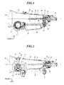
- Fig. 1 is an explanatory schematic side view illustrating the internal configuration of a power transfer system for four-wheel drive vehicles to which the present invention is applied.
- Fig. 2 is a plan view of Fig. 1 .
- Fig. 3 is a schematic view of the same example when viewed frontwards from the back of a transmission case to a front differential.
- the present invention is applied to a longitudinally disposed power transfer system for four-wheel drive vehicles which includes a front differential and a transmission in a single dividable case.
- the power transfer system is configured such that part of engine power is drawn out of the case in back of the transmission and then transmitted to the front differential via a drive pinion shaft disposed externally.
- the power transfer system for four-wheel drive vehicles of the present invention includes, in a single dividable case 20, a torque converter 30, a front differential 31, an automatic transmission mechanism section 32 and a control valve 33 of a transmission, a transfer unit (center differential) 34, and a reduction unit 35.
- the transfer unit 34 following the transmission draws part of engine power out of the case to be transmitted to the front differential 31 via a drive pinion shaft 36 disposed externally.
- the present embodiment employs, as the transmission, an unmodified longitudinal FR vehicle transmission including its case.
- the case 20 includes a torque converter case 21, a transmission case 22, a reduction case 23, and an extension case 24, which are coupled to each other in the longitudinal direction.
- the torque converter case 21 accommodates the torque converter 30 and the front differential 31.
- the transmission case 22 accommodates the automatic transmission mechanism section 32 and the control valve 33.
- the reduction case 23 and the extension case 24 accommodate the transfer unit 34 and the reduction unit 35.
- Engine power through the torque converter 30 and the automatic transmission mechanism section 32 is transmitted via a reduction drive shaft 37 to the transfer unit 34, where the power is divided to drive front wheels and rear wheels.
- the engine power for driving the rear wheels is transmitted to a rear differential via a propeller shaft (not shown), which extends rearward from the extension case 24, to rotate the right and left rear wheels via the right and left drive shafts, respectively.
- the reduction unit 35 is compact in size and includes three gears which mate with each other.
- the reduction unit 35 is configured to transmit engine power from a reduction drive gear 38 via a reduction counter gear 40 to a reduction driven gear 41, thereby rotationally driving the drive pinion shaft 36.
- the reduction drive gear 38 is relatively rotatably disposed on the rear portion of the reduction drive shaft 37.
- the reduction counter gear 40 is supported by an intermediate shaft 39 located diagonally thereunder on the left.
- the reduction driven gear 41 is secured to the rear portion of the drive pinion shaft 36.
- the drive pinion shaft 36 is located outside the transmission case 22 at a predetermined distance therefrom. This allows transmission of engine power to the front differential 31 mating with the drive pinion shaft 36, thereby rotating the right and left front wheels via the right and left drive shafts 42.
- the drive pinion shaft 36 is covered with a protective cover (not shown) which is fixed across the torque converter case 21 and the reduction case 23.
- the reduction unit 35 is not limited to the configuration of a group of gears but may also include chains, for example.
- the front differential 31 is configured to include a differential case 31a, a pinion shaft 31 b, a pair of differential bevel pinions 31 c, a pair of differential bevel gears 31d, and a hypoid gear 31e.
- the differential case 31a which is hollow, accommodates the pinion shaft 31 b which is secured to the differential case 31a with a straight pin 31f to prevent it from being dislodged.
- the pinion shaft 31b is provided, on both ends of the shaft, with the pair of rotatable differential bevel pinions 31 c.
- the differential bevel gears 31d are rotatably disposed to the right and left across the pinion shaft 31 b.
- the differential bevel gears 31d mate with the pair of differential bevel pinions 31c and are spline-engaged with the right and left drive shafts 42, so that the pinion shaft 31b serves as the differential center of the front differential 31.
- the pinion shaft 31b is offset a predetermined distance from the lateral center of the vehicle body Y/0 toward the drive pinion shaft.
- the amount of offset is defined such that the right and left drive shafts 42 coupled to the differential bevel gears 31d can be considered generally equal to each other in length.
- the differential case 31a near the pinion shaft is increased in diameter so as to be greater in outer diameter than the right and left case portions into which the drive shafts 42 are respectively inserted, and is integrated with an extended portion 31a1 which extends a predetermined distance toward the drive pinion shaft with the outer diameter maintained unchanged.
- having the pinion shaft 31b placed on the lateral center of the vehicle body Y/0 having the pinion shaft 31b offset leftward from the lateral center of the vehicle body Y/0 provides a minimum required distance over which the extended portion 31a1 is extended, thereby preventing an increase in the size of the front differential 31.
- the extended portion 31a1 has a protruding outer circumference portion, with which a flange portion 31 a2 is integrated to attach a hypoid drive gear 31e thereto so that it mates with the drive pinion shaft 36.
- the toothed surface of the hypoid drive gear 31e is disposed in close proximity to the left inner wall of the torque converter case 21.
- the pinion shaft 31b of the front differential 31 is offset a predetermined distance from the lateral center of the vehicle body Y/0 toward the drive pinion shaft 36.
- the differential case 31a near the pinion shaft 31b is extended toward the drive pinion shaft 36 where the outer diameter of the differential case 31a near the pinion shaft 31 bis maintained, and the hypoid drive gear 31e is attached to the extended portion 31a1.
- this arrangement makes it possible to use an unmodified FR vehicle transmission including a case to form a longitudinal power transfer system for a four-wheel drive vehicle.
- the pinion shaft 31b is offset to such an offset position that allows for considering the right and left drive shafts 42 coupled to the front differential 31 to be generally equal to each other in length.
- torque steer never occurs with the steering angle or suspension stroke never reduced.
- the present embodiment employs, as the transmission, an automatic transmission.
- the present invention is not limited thereto.
- the invention may also employ an FR vehicle manual transmission.
- To employ the FR vehicle manual transmission it is necessary to form a transmission case integrated with a clutch housing to contain the front differential.
- the clutch and the manual transmission mechanism for the FR vehicle can also be used with no change made thereto, the power transfer system for four-wheel drive vehicles can be provided at low costs.
Landscapes
- Engineering & Computer Science (AREA)
- Chemical & Material Sciences (AREA)
- Combustion & Propulsion (AREA)
- Transportation (AREA)
- Mechanical Engineering (AREA)
- Arrangement And Driving Of Transmission Devices (AREA)
- Arrangement Of Transmissions (AREA)
- Motor Power Transmission Devices (AREA)
Abstract
Description
- The present invention relates to a power transfer system for four-wheel drive vehicles.
- Conventionally, a power transfer system is known which is arranged longitudinally in a four-wheel drive vehicle and which includes a torque converter, a transmission, a transfer unit (or center differential), and a front differential (hereinafter referred to as the front differential) in one dividable case (e.g., see
Japanese Patent Application Laid-Open No. Hei 5-201264 - As shown in
Figs. 4 and 5 , in this type of a power transfer system for four-wheel drive vehicles, a case 1 is configured to have atorque converter case 2, atransmission case 3, and anextension case 4, which are coupled to each other in the longitudinal direction. Thetorque converter case 2 accommodates atorque converter 5 and afront differential 6. Thetransmission case 3 accommodates an automatictransmission mechanism section 7 and acontrol valve 8 of the transmission. Theextension case 4 accommodates atransfer unit 9. - Engine power transmitted through the
torque converter 5 and the automatictransmission mechanism section 7 is supplied via areduction drive shaft 10 to thetransfer unit 9, where the engine power is divided to drive the front wheels and the rear wheels. The engine power for driving the rear wheels is transmitted to the rear differential via a propeller shaft (not shown), which extends rearward from theextension case 4, to rotate the right and left rear wheels via the right and left drive shafts, respectively. - On the other hand, the engine power for driving the front wheels serves to rotationally drive a
drive pinion shaft 12, which is disposed in parallel to and diagonally below thereduction drive shaft 10, via areduction drive gear 11 and a reduction drivengear 13. In this instance, thereduction drive gear 11 is relatively rotatably disposed on the shaft of thereduction drive shaft 10, and the reduction drivengear 13 is secured to the shaft of thedrive pinion shaft 12. The engine power is thus transferred to thefront differential 6 engaged with thedrive pinion shaft 12, thereby rotating the right and left front wheels via right and left drive shafts 14 (illustrated inFig. 6 ), respectively. - As shown in
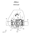
Figs. 5 and6 , ahypoid gear 6a of thefront differential 6 is securely attached to adifferential case 6c near apinion shaft 6b which serves as a differential center. This is due to the following reasons. Thepinion shaft 6b has, on both ends of the shaft, a pair ofdifferential bevel pinions 6e which rotate in the longitudinal direction about the lateral center of the vehicle body Y/0. Thedifferential bevel pinions 6e also mate with a pair of right and leftdifferential bevel gears 6d which are disposed on the right and left sides of the shaft, respectively. This arrangement allows thedifferential case 6c near thepinion shaft 6b to have the maximum outer diameter. This configuration is thus preferable in terms of power transmission. - Furthermore, the
pinion shaft 6b is located on the lateral center of the vehicle body Y/0, so that the right andleft drive shafts 14 spline-engaged with thedifferential bevel gears 6d are equal in length to each other. This configuration is intended to prevent torque steer (being a phenomenon in which the steering wheel is turned in one direction during an abrupt start of the vehicle) and provide a large steering angle or suspension stroke. - However, in the aforementioned conventional power transfer system for four-wheel drive vehicles, the
drive pinion shaft 12 is contained in thetransmission case 3. For this reason, most parts of the transmission need to be custom designed and manufactured at additional cost and with consequently low versatility. - In this context, a power transfer system for four-wheel drive vehicles may be conceived which allows a front-engine rear-drive (FR) vehicle transmission to be employed with no change made thereto, so that part of the engine power is drawn out of the case in back of the transmission and then transferred to the front differential via a drive pinion shaft disposed externally.
- However, in such a case, using a front differential configured in the conventional manner would require it to be significantly offset laterally from the lateral center of the vehicle body Y/0, depending on the amount of offset of the external drive pinion shaft. This would in turn cause not only the power transmission system to be increased in size but also the right and left drive shafts to be unequal in length, resulting in the torque steer being produced or in the steering angle and suspension stroke being reduced.
- The present invention was developed in view of the aforementioned problems with the conventional technique. It is therefore an object of the present invention to provide a power transfer system for four-wheel drive vehicles which allows the power transmission system to be compact and the front differential to be located near the lateral center of the vehicle body Y/0 even when an unmodified FR vehicle transmission is used.
- In order to achieve the aforementioned object, a first aspect of the present invention provides a power transfer system for four-wheel drive vehicles which is longitudinally disposed and includes a single dividable case, a front differential and a transmission which are accommodated in the dividable case. The power transfer system is configured to draw part of engine power out of the case in back of the transmission, to then be transferred to the front differential via a drive pinion shaft disposed externally.
- The front differential is configured such that a pinion shaft disposed to serve as a differential center within a differential case is offset a predetermined distance from a lateral center of a vehicle body toward the drive pinion shaft. An extended portion is also provided which is formed by extending the differential case near the pinion shaft toward the drive pinion shaft, where the outer diameter of the differential case near the pinion shaft is maintained. A hypoid drive gear mating with the drive pinion shaft is attached to the extended portion.
- In order to achieve the aforementioned object, a second aspect of the present invention is characterized in that the predetermined distance is defined such that right and left drive shafts coupled to the front differential can be considered generally equal in length to each other.
- According to the first and second aspects of the present invention, the pinion shaft of the front differential is offset a predetermined distance from the lateral center of the vehicle body toward the drive pinion shaft. The differential case near the pinion shaft is extended toward the drive pinion shaft, where the outer diameter of the differential case near the pinion shaft is maintained, to attach the hypoid drive gear to the extended portion. This allows for forming a longitudinal power transfer system for four-wheel drive vehicles using an FR vehicle transmission without an increase in the size of the front differential and the torque converter case. The front differential can also be disposed near the lateral center of the vehicle body. Furthermore, the offset position of the pinion shaft is defined such that the right and left drive shafts coupled to the front differential can be considered generally equal in length to each other. Thus, torque steer will not occur and the steering angle or suspension stroke is not reduced.
- According to the power transfer system for four-wheel drive vehicles of the present invention, the pinion shaft of the front differential is offset a predetermined distance from the lateral center of the vehicle body toward the drive pinion shaft. The amount of offset is defined such that the right and left drive shafts coupled to the front differential can be considered generally equal in length to each other.
- Furthermore, the differential case near the pinion shaft is extended toward the drive pinion shaft where the outer diameter of the differential case near the pinion shaft is maintained to attach the hypoid drive gear to the extended portion. This allows for making the power transmission system to be compact even when an unmodified FR vehicle transmission is used. The front differential can also be disposed near the lateral center of the vehicle body.
- These and other objects and advantages of the present invention will become clear from the following description with reference to the accompanying drawings, wherein:
- Fig. 1
- is an explanatory schematic side view illustrating the internal configuration of a power transfer system for four-wheel drive vehicles to which the present invention is applied;
- Fig. 2
- is a plan view of the embodiment in
Fig. 1 ; - Fig. 3
- is a schematic view of the same example when viewed frontwards from the back of a transmission case to a front differential;
- Fig. 4
- is an explanatory schematic side view illustrating the internal configuration of a conventional power transfer system for four-wheel drive vehicles;
- Fig. 5
- is a plan view of the conventional system in
Fig. 4 ; and - Fig. 6
- is a schematic view of the same example when viewed frontwards from the back of a transmission case to the front differential shown in
Fig. 4 . - Now, the present invention will be described below in more detail with reference to the accompanying drawings in accordance with the embodiment.
-
Fig. 1 is an explanatory schematic side view illustrating the internal configuration of a power transfer system for four-wheel drive vehicles to which the present invention is applied.Fig. 2 is a plan view ofFig. 1 .Fig. 3 is a schematic view of the same example when viewed frontwards from the back of a transmission case to a front differential. - The present invention is applied to a longitudinally disposed power transfer system for four-wheel drive vehicles which includes a front differential and a transmission in a single dividable case. The power transfer system is configured such that part of engine power is drawn out of the case in back of the transmission and then transmitted to the front differential via a drive pinion shaft disposed externally.
- As shown in
Figs. 1 to 3 , the power transfer system for four-wheel drive vehicles of the present invention includes, in a singledividable case 20, atorque converter 30, a front differential 31, an automatictransmission mechanism section 32 and acontrol valve 33 of a transmission, a transfer unit (center differential) 34, and areduction unit 35. Thetransfer unit 34 following the transmission draws part of engine power out of the case to be transmitted to the front differential 31 via adrive pinion shaft 36 disposed externally. - Note that the present embodiment employs, as the transmission, an unmodified longitudinal FR vehicle transmission including its case.
- More specifically, the
case 20 includes atorque converter case 21, atransmission case 22, areduction case 23, and anextension case 24, which are coupled to each other in the longitudinal direction. Thetorque converter case 21 accommodates thetorque converter 30 and the front differential 31. Thetransmission case 22 accommodates the automatictransmission mechanism section 32 and thecontrol valve 33. Thereduction case 23 and theextension case 24 accommodate thetransfer unit 34 and thereduction unit 35. - Engine power through the
torque converter 30 and the automatictransmission mechanism section 32 is transmitted via areduction drive shaft 37 to thetransfer unit 34, where the power is divided to drive front wheels and rear wheels. The engine power for driving the rear wheels is transmitted to a rear differential via a propeller shaft (not shown), which extends rearward from theextension case 24, to rotate the right and left rear wheels via the right and left drive shafts, respectively. - Conversely, the engine power for driving the front wheels is drawn out of the case by the
reduction unit 35. Thereduction unit 35 is compact in size and includes three gears which mate with each other. Thereduction unit 35 is configured to transmit engine power from areduction drive gear 38 via areduction counter gear 40 to a reduction drivengear 41, thereby rotationally driving thedrive pinion shaft 36. In this instance, thereduction drive gear 38 is relatively rotatably disposed on the rear portion of thereduction drive shaft 37. - The
reduction counter gear 40 is supported by anintermediate shaft 39 located diagonally thereunder on the left. The reduction drivengear 41 is secured to the rear portion of thedrive pinion shaft 36. Thedrive pinion shaft 36 is located outside thetransmission case 22 at a predetermined distance therefrom. This allows transmission of engine power to the front differential 31 mating with thedrive pinion shaft 36, thereby rotating the right and left front wheels via the right and leftdrive shafts 42. - Note that the
drive pinion shaft 36 is covered with a protective cover (not shown) which is fixed across thetorque converter case 21 and thereduction case 23. Note also that thereduction unit 35 is not limited to the configuration of a group of gears but may also include chains, for example. - As shown in
Figs. 2 and3 , the front differential 31 is configured to include adifferential case 31a, apinion shaft 31 b, a pair of differential bevel pinions 31 c, a pair ofdifferential bevel gears 31d, and ahypoid gear 31e. - The
differential case 31a, which is hollow, accommodates thepinion shaft 31 b which is secured to thedifferential case 31a with astraight pin 31f to prevent it from being dislodged. Thepinion shaft 31b is provided, on both ends of the shaft, with the pair of rotatable differential bevel pinions 31 c. Furthermore, thedifferential bevel gears 31d are rotatably disposed to the right and left across thepinion shaft 31 b. Thedifferential bevel gears 31d mate with the pair ofdifferential bevel pinions 31c and are spline-engaged with the right and leftdrive shafts 42, so that thepinion shaft 31b serves as the differential center of the front differential 31. - Furthermore, with the
differential case 31a rotatably supported on thetorque converter case 21 via right and lefttapered roller bearings 43, thepinion shaft 31b is offset a predetermined distance from the lateral center of the vehicle body Y/0 toward the drive pinion shaft. The amount of offset is defined such that the right and leftdrive shafts 42 coupled to thedifferential bevel gears 31d can be considered generally equal to each other in length. - Furthermore, the
differential case 31a near the pinion shaft is increased in diameter so as to be greater in outer diameter than the right and left case portions into which thedrive shafts 42 are respectively inserted, and is integrated with an extended portion 31a1 which extends a predetermined distance toward the drive pinion shaft with the outer diameter maintained unchanged. Compared with having thepinion shaft 31b placed on the lateral center of the vehicle body Y/0, having thepinion shaft 31b offset leftward from the lateral center of the vehicle body Y/0 provides a minimum required distance over which the extended portion 31a1 is extended, thereby preventing an increase in the size of the front differential 31. - Furthermore, the extended portion 31a1 has a protruding outer circumference portion, with which a
flange portion 31 a2 is integrated to attach ahypoid drive gear 31e thereto so that it mates with thedrive pinion shaft 36. With thehypoid drive gear 31e attached to theflange portion 31 a2, the toothed surface of thehypoid drive gear 31e is disposed in close proximity to the left inner wall of thetorque converter case 21. - As described above, according to the power transfer system for four-wheel drive vehicles of the present invention, the
pinion shaft 31b of the front differential 31 is offset a predetermined distance from the lateral center of the vehicle body Y/0 toward thedrive pinion shaft 36. In addition, thedifferential case 31a near thepinion shaft 31b is extended toward thedrive pinion shaft 36 where the outer diameter of thedifferential case 31a near thepinion shaft 31 bis maintained, and thehypoid drive gear 31e is attached to the extended portion 31a1. - Thus, without increase in the size of the front differential 31 and the
torque converter case 21, this arrangement makes it possible to use an unmodified FR vehicle transmission including a case to form a longitudinal power transfer system for a four-wheel drive vehicle. Furthermore, thepinion shaft 31b is offset to such an offset position that allows for considering the right and leftdrive shafts 42 coupled to the front differential 31 to be generally equal to each other in length. Thus, torque steer never occurs with the steering angle or suspension stroke never reduced. - Note that the present embodiment employs, as the transmission, an automatic transmission. However, the present invention is not limited thereto. The invention may also employ an FR vehicle manual transmission. To employ the FR vehicle manual transmission, it is necessary to form a transmission case integrated with a clutch housing to contain the front differential. However, since the clutch and the manual transmission mechanism for the FR vehicle can also be used with no change made thereto, the power transfer system for four-wheel drive vehicles can be provided at low costs.
Claims (2)
- A power transfer system for four-wheel drive vehicles which is longitudinally disposed and includes a single dividable case (20), a front differential (31) and a transmission (32) which are accommodated in the dividable case (20), the power transfer system being configured to draw part of engine power out of the case in back of the transmission (32), to then be transferred to the front differential (31) via a drive pinion shaft (36) disposed externally,
wherein the front differential (31) is configured such that a pinion shaft (31b) disposed to serve as a differential center within a differential case (31a) is offset a predetermined distance from a lateral center of a vehicle body (Y/O) toward the drive pinion shaft (36), an extended portion (31a1) is provided which is formed by extending the differential case (31a) near the pinion shaft (31b) toward the drive pinion shaft (36), where the outer diameter of the differential case (31a) near the pinion shaft (31b) is maintained, and a hypoid drive gear (31e) mating with the drive pinion shaft (36) is attached to the extended portion (31a1). - The power transfer system according to claim 1,
wherein the predetermined distance is defined such that right and left drive shafts (14, 42) coupled to the front differential (31) can be considered generally equal in length to each other.
Applications Claiming Priority (1)
| Application Number | Priority Date | Filing Date | Title |
|---|---|---|---|
| JP2007020418A JP2008184086A (en) | 2007-01-31 | 2007-01-31 | Power transmission device for four-wheel drive vehicles |
Publications (1)
| Publication Number | Publication Date |
|---|---|
| EP1953026A1 true EP1953026A1 (en) | 2008-08-06 |
Family
ID=39227069
Family Applications (1)
| Application Number | Title | Priority Date | Filing Date |
|---|---|---|---|
| EP08101072A Withdrawn EP1953026A1 (en) | 2007-01-31 | 2008-01-29 | Power transfer system for four-wheel drive vehicles |
Country Status (3)
| Country | Link |
|---|---|
| US (1) | US20080179129A1 (en) |
| EP (1) | EP1953026A1 (en) |
| JP (1) | JP2008184086A (en) |
Citations (6)
| Publication number | Priority date | Publication date | Assignee | Title |
|---|---|---|---|---|
| GB1537585A (en) * | 1975-07-12 | 1979-01-04 | Bergische Achsen Kotz Soehne | Differential gear assemblies |
| DE3418557A1 (en) * | 1984-05-18 | 1985-11-21 | Audi AG, 8070 Ingolstadt | Drive assembly which can be installed longitudinally in a motor vehicle |
| US4714129A (en) * | 1985-03-02 | 1987-12-22 | Dr. Ing. H.C.F. Porsche Aktiengesellschaft | Transmission system with intermediate differential for all-wheel drive vehicle |
| EP0282610A1 (en) * | 1987-03-16 | 1988-09-21 | Dr.Ing.h.c. F. Porsche Aktiengesellschaft | Front wheel transmission for an all-wheel drive vehicle |
| JPH05201264A (en) | 1992-01-27 | 1993-08-10 | Fuji Heavy Ind Ltd | Four-wheel drive vehicle with center differential device |
| US20060289217A1 (en) * | 2005-06-23 | 2006-12-28 | Volkswagen Ag | Drive train for a motor vehicle |
Family Cites Families (6)
| Publication number | Priority date | Publication date | Assignee | Title |
|---|---|---|---|---|
| JPH1044820A (en) * | 1996-07-30 | 1998-02-17 | Fuji Heavy Ind Ltd | Vehicular differential-limiting device |
| EP1136301A3 (en) * | 2000-03-24 | 2005-04-06 | Fuji Jukogyo Kabushiki Kaisha | "Power transmitting system for four-wheel drive vehicle" |
| US6605018B2 (en) * | 2001-08-23 | 2003-08-12 | Visteon Global Technologies, Inc. | Power transfer unit |
| US6620071B1 (en) * | 2002-03-27 | 2003-09-16 | Visteon Global Technologies, Inc. | Power takeoff unit with center differential construction |
| US20050087380A1 (en) * | 2003-10-24 | 2005-04-28 | Todd Brown | Variator in a four wheel drive |
| US7207409B2 (en) * | 2004-03-10 | 2007-04-24 | American Axle & Manufacturing, Inc. | Two speed all wheel drive system |
-
2007
- 2007-01-31 JP JP2007020418A patent/JP2008184086A/en active Pending
-
2008
- 2008-01-29 EP EP08101072A patent/EP1953026A1/en not_active Withdrawn
- 2008-01-31 US US12/023,227 patent/US20080179129A1/en not_active Abandoned
Patent Citations (6)
| Publication number | Priority date | Publication date | Assignee | Title |
|---|---|---|---|---|
| GB1537585A (en) * | 1975-07-12 | 1979-01-04 | Bergische Achsen Kotz Soehne | Differential gear assemblies |
| DE3418557A1 (en) * | 1984-05-18 | 1985-11-21 | Audi AG, 8070 Ingolstadt | Drive assembly which can be installed longitudinally in a motor vehicle |
| US4714129A (en) * | 1985-03-02 | 1987-12-22 | Dr. Ing. H.C.F. Porsche Aktiengesellschaft | Transmission system with intermediate differential for all-wheel drive vehicle |
| EP0282610A1 (en) * | 1987-03-16 | 1988-09-21 | Dr.Ing.h.c. F. Porsche Aktiengesellschaft | Front wheel transmission for an all-wheel drive vehicle |
| JPH05201264A (en) | 1992-01-27 | 1993-08-10 | Fuji Heavy Ind Ltd | Four-wheel drive vehicle with center differential device |
| US20060289217A1 (en) * | 2005-06-23 | 2006-12-28 | Volkswagen Ag | Drive train for a motor vehicle |
Also Published As
| Publication number | Publication date |
|---|---|
| US20080179129A1 (en) | 2008-07-31 |
| JP2008184086A (en) | 2008-08-14 |
Similar Documents
| Publication | Publication Date | Title |
|---|---|---|
| US7306536B2 (en) | Tandem axle system | |
| WO2007133367A2 (en) | Electronic all-wheel drive module with overrunning clutch differential | |
| EP0305997A2 (en) | Four-wheel drive vehicle | |
| US7637343B2 (en) | Small-sized vehicle | |
| AU2001282320A1 (en) | Power train | |
| US8381861B2 (en) | Power transfer unit with dual hypoid geartrain | |
| US20060135307A1 (en) | Powertrain arrangement for a skid-steer vehicle | |
| EP1652718A1 (en) | Pinion housing with contaminant deflector | |
| US6848337B2 (en) | Transmission mechanism for driving four wheels | |
| US6702706B2 (en) | Power transmission apparatus for four-wheel drive vehicle | |
| EP0096904B1 (en) | Differential assembly for distribution of torque between the front and rear axles of an automotive vehicle | |
| US20080179129A1 (en) | Power transfer system for four-wheel drive vehicles | |
| US7896120B2 (en) | Small-sized vehicle with improved drivetrain | |
| US6837820B1 (en) | Differential drive gear assembly | |
| US6620069B2 (en) | Power transfer unit | |
| DE102017103913B4 (en) | Power transmission unit with axle locking system and motor vehicle equipped therewith | |
| GB2378227A (en) | A differential arrangement having a central composite differential | |
| US6854359B1 (en) | Transmission mechanism for driving four wheels | |
| JPS59190028A (en) | Power transmission device | |
| JPS62246646A (en) | Differential gear device | |
| JP2006103634A (en) | Working vehicle | |
| JPH03103648A (en) | Lubricating device for differential device | |
| JP2026083976A (en) | All-wheel drive vehicle | |
| JPS60135328A (en) | Four-wheel driven car | |
| JPS6317699Y2 (en) |
Legal Events
| Date | Code | Title | Description |
|---|---|---|---|
| PUAI | Public reference made under article 153(3) epc to a published international application that has entered the european phase |
Free format text: ORIGINAL CODE: 0009012 |
|
| AK | Designated contracting states |
Kind code of ref document: A1 Designated state(s): AT BE BG CH CY CZ DE DK EE ES FI FR GB GR HR HU IE IS IT LI LT LU LV MC MT NL NO PL PT RO SE SI SK TR |
|
| AX | Request for extension of the european patent |
Extension state: AL BA MK RS |
|
| 17P | Request for examination filed |
Effective date: 20090204 |
|
| 17Q | First examination report despatched |
Effective date: 20090317 |
|
| AKX | Designation fees paid |
Designated state(s): DE GB |
|
| STAA | Information on the status of an ep patent application or granted ep patent |
Free format text: STATUS: THE APPLICATION HAS BEEN WITHDRAWN |
|
| 18W | Application withdrawn |
Effective date: 20090626 |