EP1953016A1 - Traverse motion HVAC valve - Google Patents
Traverse motion HVAC valve Download PDFInfo
- Publication number
- EP1953016A1 EP1953016A1 EP20080150649 EP08150649A EP1953016A1 EP 1953016 A1 EP1953016 A1 EP 1953016A1 EP 20080150649 EP20080150649 EP 20080150649 EP 08150649 A EP08150649 A EP 08150649A EP 1953016 A1 EP1953016 A1 EP 1953016A1
- Authority
- EP
- European Patent Office
- Prior art keywords
- plate
- shaft
- outlet
- assembly
- set forth
- Prior art date
- Legal status (The legal status is an assumption and is not a legal conclusion. Google has not performed a legal analysis and makes no representation as to the accuracy of the status listed.)
- Granted
Links
Images


Classifications
-
- B—PERFORMING OPERATIONS; TRANSPORTING
- B60—VEHICLES IN GENERAL
- B60H—ARRANGEMENTS OF HEATING, COOLING, VENTILATING OR OTHER AIR-TREATING DEVICES SPECIALLY ADAPTED FOR PASSENGER OR GOODS SPACES OF VEHICLES
- B60H1/00—Heating, cooling or ventilating devices
- B60H1/00642—Control systems or circuits; Control members or indication devices for heating, cooling or ventilating devices
- B60H1/00664—Construction or arrangement of damper doors
- B60H1/00692—Damper doors moved by translation, e.g. curtain doors
-
- Y—GENERAL TAGGING OF NEW TECHNOLOGICAL DEVELOPMENTS; GENERAL TAGGING OF CROSS-SECTIONAL TECHNOLOGIES SPANNING OVER SEVERAL SECTIONS OF THE IPC; TECHNICAL SUBJECTS COVERED BY FORMER USPC CROSS-REFERENCE ART COLLECTIONS [XRACs] AND DIGESTS
- Y10—TECHNICAL SUBJECTS COVERED BY FORMER USPC
- Y10T—TECHNICAL SUBJECTS COVERED BY FORMER US CLASSIFICATION
- Y10T137/00—Fluid handling
- Y10T137/8593—Systems
- Y10T137/86493—Multi-way valve unit
- Y10T137/86831—Selective opening of plural ports
Definitions
- the invention relates to a climate control system also commonly referred to as an HVAC system (heating, ventilation, and air conditioning) for a vehicle and more specifically to a valve assembly for controlling airflow through an outlet of the climate control system.
- HVAC system heating, ventilation, and air conditioning
- HVAC heating, ventilation and air conditioning
- a housing an evaporator, a heater core having a housing, an evaporator assembly coupled to the housing, an evaporator, a heater core, an air inlet, a fan and various doors or mode valves for controlling the volume and direction of air flow and generating outlet air of a desired volume and temperature.
- these components receive, temper and direct the flow of forced air through several outlets or vents in the vehicle.
- the outlets through which the forced air ultimately exits are determined by the various doors which move between open and closed positions and cause air flow to be forced in one direction or another or a combination of both. Air may be directed to various areas of the car depending on the state of the mode valves.
- air may be forced through outlets directed at the windshield in a defrost or defog mode, or through outlets directed at mid-height level in an air-conditioning mode, or to lower outlets directed to the floor in a heat mode, or various combinations thereof.
- the housing has a plurality of outlets each having a periphery. More recently, the housing is defined by two oppositely facing outlets.
- a motor or mechanism is attached to a shaft that is rotatably supported by the housing outside the peripheries of the outlets.
- a rotary plate valve is disposed about the shaft and is movable to cover or block air from exiting the outlets in a closed position and uncover or unblock the outlets to permit air to exit the housing in an open position.
- the plate valve's periphery is connected to the shaft and the plate valve is covered with material which complies with the interior of the housing in order to form an air seal.
- This material generally is made from a compressible cellular foam or molded thermoset rubber that forms a wiper.
- HVAC systems having these rotary plate valves do not have a means to direct the cold air from the evaporator core and hot air from the heater towards the outlet in order to achieve a desired outlet temperature while in an open position. Additionally, these rotary plate valves do not have a means to meter a portion of these airstreams while in an intermittent position between open and closed. These intermittent positions are desired in order to achieve the proper air balance between the various outlets such as the lower outlets directed to the floor in a heat mode.
- Hoffman et al. teach a rotary valve for sealing outlets defined by a curved surface.
- the air valve has a radius of curvature measured from an axis which is offset from that of the radius of curvature for the surface defining the outlets being sealed.
- This valve's plate and sealing surface which cover or uncover an outlet are parallel with the axis of the shaft and as such is only able to seal an outlet that is located parallel with the axis of the shaft.
- the contact pressure is therefore high when the valve is in a closed position and diminishes to zero after the valve is rotated to an open position.
- valves which move between open and closed positions
- a valve that does not produce high frictional loads while simultaneously aiding in directing air flow through the outlet of the housing.
- a valve that can direct the cold air from the evaporator core and hot air from the heater towards the outlet in order to achieve a desired outlet temperature and can meter a portion of these airstreams while in an intermittent position between open and closed.
- a rotary valve whose plate and sealing surface is perpendicular to the shaft.
- the invention provides such an assembly for controlling air flow in an HVAC system wherein the rotatable shaft has a threaded section.
- the interior surface of the plate valve is threaded and is in threaded engagement with the threaded section of the shaft for moving the plate valve axially away from the outlet in response to rotation of the shaft in a first direction and moving the first plate valve axially toward the outlet in response to rotation of the shaft in a second direction opposite to the first direction while the plate valve is kept from rotating due to its relative engagement with the outlet.
- the invention provides a valve which uses linear valve motion in order to seal an outlet with a uniform seal about the periphery. Moreover, the linear motion eliminates the friction related to sliding described in the prior art and thereby reduces the risk of failure or fatigue. Additionally, the invention structurally baffles a hot or cold airstream towards the outlet to facilitate air mixing in order to achieve the desired outlet temperature.
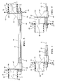
- Figure 1 is a cross-sectional view of an embodiment of an HVAC system
- Figure 2 is a perspective cross-sectional view of another embodiment of the invention illustrating a pair of plate valves
- Figure 3 is a fragmentary view of the embodiment of Figure 2 illustrating the shaft, valves and guide;
- Figure 4 is a fragmentary view of the embodiment of Figure 3 illustrating the valve in a closed position
- Figure 5 is a fragmentary view of the embodiment of Figure 3 illustrating the valve in an open position
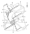
- Figure 6 is fragmentary cross-sectional view of the embodiment shown in Figure 3 ;
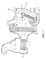
- Figure 7 is an alternative embodiment of the embodiment of an HVAC system.
- a climate control or HVAC system 20 can be disposed in a vehicle to control conditions associated with air inside a passenger compartment of a vehicle.
- the exemplary climate control system 20 includes a blower 22 for blowing air through the housing 24 and a plurality of heat exchangers 26 for heating and cooling the air in the housing 24, as shown in Figure 1 and 7 .
- the housing 24 defines a first outlet 28 having a first outer periphery 30 and a second outlet 32 having a second outer periphery 34.
- the outlets 28, 32 oppositely face one another.
- the first outer periphery 30 may have a fan-like shape extending radially from the shaft, but is not limited to this geometry, and defines a first contoured surface 36.
- the second outer periphery 34 may similarly have a fan-like shaped, but is not limited to this geometry, and defines a second contoured surface 38 equal in size and shape to the first contoured surface 36.
- a shaft 40 is rotatably supported by the housing 24 outside the peripheries 30, 34 of the outlets 28, 32 and extends along an axis A.
- the shaft 40 extends between and perpendicular to the peripheries 30, 34 of the outlets 28, 32.
- the assembly 20 includes a first plate valve 42 for covering the first outer periphery 30 of the first outlet 28 in a closed position and axially movable to an open position.
- Figures 4 and 5 illustrate the first plate valve 42 in the open and closed positions respectively.
- the first plate valve 42 includes a first bushing 44 defining a first interior surface 46 surrounding the shaft 40.
- the first valve 42 also includes a first plate extending radially from the first bushing 44 in a fan-like shape for sealing the first periphery 30 of the first outlet 28.
- a first reinforcing web 48 interconnects the first bushing 44 and the first plate for reinforcing the first plate on the first bushing 44.
- a second plate valve 50 is included for covering the second outer periphery 34 of the second outlet 32 in a closed position and movable to an open position.
- the second valve 50 includes a second bushing 52 defining a second interior surface 54 surrounding the shaft 40.
- the second valve 50 also includes a second plate extending radially from the second bushing 52 in a fan-like shape for sealing the second periphery 34 of the second outlet 32.
- a second reinforcing web 56 interconnects the second bushing 52 and the second plate for reinforcing the second plate on the second bushing 52.
- the assembly 20 is distinguished by the shaft 40 having oppositely threaded first and second sections 58, 60 disposed at opposite ends of the shaft 40 as best shown in Figure 3 .
- the interior surfaces 46, 54 of the bushings 44, 52 are oppositely threaded, and the first interior surface 46 of the first bushing 44 is in threaded engagement with the first section 58 of the shaft 40, as illustrated in Figure 3 .
- the second interior surface 54 of the second bushing 52 is in threaded engagement with the second section 60 of the shaft 40.
- the threaded engagements move the plate valves 42, 50 axially toward one another in response to rotation of the shaft 40 in a first direction and move the plate valves 42, 50 axially away from one another in response to rotation of the shaft 40 in a second direction opposite to the first direction.
- the assembly 20 includes a guide 62, generally indicated, for limiting rotation of the valves 42, 50 relative to the axis A in response to rotation of the shaft 40.
- the first valve 42 may include a first guide plate 64 and the second valve 50 may include a second guide plate 66 to define the guide 62.
- the first guide plate 64 defines a first upper surface 68 and the second guide plate 66 defines a second upper surface 70.
- the first upper surface 68 of the first guide plate 64 extends parallel to and through the first contoured surface 36 of the first outlet 28 for limiting rotation of the first valve 42 relative to the axis A in response to rotation of the shaft 40.
- the first guide plate 64 defines a first lower surface 72 which has a contoured shape extending parallel to the axis A for directing radial air flow axially through the first outlet 28 in the open position.
- the second upper surface 70 of the second guide plate 66 extends parallel to and through the second contoured surface 38 of the second outlet 32 for restricting rotation of the second valve 50 about the axis A in response to rotation of the shaft 40.
- the second guide plate 66 defines a second lower surface 74 which has a contoured shape extending parallel to the axis A for directing radial air flow axially through the second outlet 32 in the open position.
- the upper surfaces 68, 70 of the guide plates 64, 66 profile the contoured surfaces of the outlet and the lower surfaces 72, 74 are flat, however the surfaces of the guide plates 64, 66 are not limited to this geometry.
- FIG. 7 illustrates an alternative embodiment of the HVAC system having a plurality of rotary valves 80 and detailing an arrangement where the plate valves 42, 50 would be able to catch the air flow and redirect the path of the air flow into the outlets 28, 32.
Landscapes
- Physics & Mathematics (AREA)
- Thermal Sciences (AREA)
- Engineering & Computer Science (AREA)
- Mechanical Engineering (AREA)
- Air-Conditioning For Vehicles (AREA)
- Check Valves (AREA)
- Valve-Gear Or Valve Arrangements (AREA)
- Vehicle Body Suspensions (AREA)
- Mechanically-Actuated Valves (AREA)
- Sliding Valves (AREA)
- Air-Flow Control Members (AREA)
Abstract
Description
- The invention relates to a climate control system also commonly referred to as an HVAC system (heating, ventilation, and air conditioning) for a vehicle and more specifically to a valve assembly for controlling airflow through an outlet of the climate control system.
- Conventional heating, ventilation and air conditioning (HVAC) systems for vehicles generally include a housing, an evaporator, a heater core having a housing, an evaporator assembly coupled to the housing, an evaporator, a heater core, an air inlet, a fan and various doors or mode valves for controlling the volume and direction of air flow and generating outlet air of a desired volume and temperature. Together these components receive, temper and direct the flow of forced air through several outlets or vents in the vehicle. The outlets through which the forced air ultimately exits are determined by the various doors which move between open and closed positions and cause air flow to be forced in one direction or another or a combination of both. Air may be directed to various areas of the car depending on the state of the mode valves. For example, air may be forced through outlets directed at the windshield in a defrost or defog mode, or through outlets directed at mid-height level in an air-conditioning mode, or to lower outlets directed to the floor in a heat mode, or various combinations thereof. Generally, designs have been utilized in which the housing has a plurality of outlets each having a periphery. More recently, the housing is defined by two oppositely facing outlets. A motor or mechanism is attached to a shaft that is rotatably supported by the housing outside the peripheries of the outlets. A rotary plate valve is disposed about the shaft and is movable to cover or block air from exiting the outlets in a closed position and uncover or unblock the outlets to permit air to exit the housing in an open position. The plate valve's periphery is connected to the shaft and the plate valve is covered with material which complies with the interior of the housing in order to form an air seal. This material generally is made from a compressible cellular foam or molded thermoset rubber that forms a wiper. As the shaft rotates, the plate valve rotates with the shaft so that the foam or rubber attached to the plate valve seals the outlets.
- These rotary plate valves require the plate and its seal to be in sliding contact with the housing when alternating between the open and closed positions. Such a sliding valve requires relatively high contact pressure in order to compress the foam or deform the rubber wiper in order to achieve a desired seal.
- Furthermore, these rotary plate valves rely on a torque limited motor to rotate the shaft end either directly or remotely via a cam, link and lever in order to move the valve plate to the open and closed positions. When the contact pressure is too high for the motor to overcome, the plate valve can become immobilized in an undesired position and may result in failure of the motor. HVAC systems having these rotary plate valves do not have a means to direct the cold air from the evaporator core and hot air from the heater towards the outlet in order to achieve a desired outlet temperature while in an open position. Additionally, these rotary plate valves do not have a means to meter a portion of these airstreams while in an intermittent position between open and closed. These intermittent positions are desired in order to achieve the proper air balance between the various outlets such as the lower outlets directed to the floor in a heat mode.
- Examples of rotary valves in HVAC systems are included in U.S. Patents 4,683,913 to Hoffman et al. and 5,009,392 to Ostrand.
- Hoffman et al. teach a rotary valve for sealing outlets defined by a curved surface. The air valve has a radius of curvature measured from an axis which is offset from that of the radius of curvature for the surface defining the outlets being sealed. This valve's plate and sealing surface which cover or uncover an outlet are parallel with the axis of the shaft and as such is only able to seal an outlet that is located parallel with the axis of the shaft. The contact pressure is therefore high when the valve is in a closed position and diminishes to zero after the valve is rotated to an open position.
- Although the prior art provides valves which move between open and closed positions, there remains a need for a valve that does not produce high frictional loads while simultaneously aiding in directing air flow through the outlet of the housing. Furthermore, there also remains a need for a valve that can direct the cold air from the evaporator core and hot air from the heater towards the outlet in order to achieve a desired outlet temperature and can meter a portion of these airstreams while in an intermittent position between open and closed. Additionally, there remains a need for a rotary valve whose plate and sealing surface is perpendicular to the shaft.
- The invention provides such an assembly for controlling air flow in an HVAC system wherein the rotatable shaft has a threaded section. The interior surface of the plate valve is threaded and is in threaded engagement with the threaded section of the shaft for moving the plate valve axially away from the outlet in response to rotation of the shaft in a first direction and moving the first plate valve axially toward the outlet in response to rotation of the shaft in a second direction opposite to the first direction while the plate valve is kept from rotating due to its relative engagement with the outlet.
- The invention provides a valve which uses linear valve motion in order to seal an outlet with a uniform seal about the periphery. Moreover, the linear motion eliminates the friction related to sliding described in the prior art and thereby reduces the risk of failure or fatigue. Additionally, the invention structurally baffles a hot or cold airstream towards the outlet to facilitate air mixing in order to achieve the desired outlet temperature.
- Other advantages of the present invention will be readily appreciated, as the same becomes better understood by reference to the following detailed description when considered in connection with the accompanying drawings wherein:
-
Figure 1 is a cross-sectional view of an embodiment of an HVAC system; -
Figure 2 is a perspective cross-sectional view of another embodiment of the invention illustrating a pair of plate valves; -
Figure 3 is a fragmentary view of the embodiment ofFigure 2 illustrating the shaft, valves and guide; -
Figure 4 is a fragmentary view of the embodiment ofFigure 3 illustrating the valve in a closed position; -
Figure 5 is a fragmentary view of the embodiment ofFigure 3 illustrating the valve in an open position; -
Figure 6 is fragmentary cross-sectional view of the embodiment shown inFigure 3 ; and -
Figure 7 is an alternative embodiment of the embodiment of an HVAC system. - A plurality of different embodiments of the invention are shown in the Figures of the application. Similar features are shown in the various embodiments of the invention. Similar features are structured similarly, operate similarly, and/or have the same function unless otherwise indicated by the drawings or this specification. Furthermore, particular features of one embodiment can replace corresponding features in another embodiment unless otherwise indicated by the drawings or this specification.
- A climate control or
HVAC system 20 can be disposed in a vehicle to control conditions associated with air inside a passenger compartment of a vehicle. The exemplaryclimate control system 20 includes ablower 22 for blowing air through thehousing 24 and a plurality ofheat exchangers 26 for heating and cooling the air in thehousing 24, as shown inFigure 1 and7 . - Referring to
Figures 3-6 , thehousing 24 defines afirst outlet 28 having a firstouter periphery 30 and asecond outlet 32 having a secondouter periphery 34. Theoutlets outer periphery 30 may have a fan-like shape extending radially from the shaft, but is not limited to this geometry, and defines a first contouredsurface 36. The secondouter periphery 34 may similarly have a fan-like shaped, but is not limited to this geometry, and defines a second contouredsurface 38 equal in size and shape to the first contouredsurface 36. - A
shaft 40 is rotatably supported by thehousing 24 outside theperipheries outlets shaft 40 extends between and perpendicular to theperipheries outlets - The
assembly 20 includes afirst plate valve 42 for covering the firstouter periphery 30 of thefirst outlet 28 in a closed position and axially movable to an open position.Figures 4 and 5 illustrate thefirst plate valve 42 in the open and closed positions respectively. Thefirst plate valve 42 includes afirst bushing 44 defining a firstinterior surface 46 surrounding theshaft 40. Thefirst valve 42 also includes a first plate extending radially from the first bushing 44 in a fan-like shape for sealing thefirst periphery 30 of thefirst outlet 28. A first reinforcingweb 48 interconnects thefirst bushing 44 and the first plate for reinforcing the first plate on thefirst bushing 44. - A
second plate valve 50 is included for covering the secondouter periphery 34 of thesecond outlet 32 in a closed position and movable to an open position. Thesecond valve 50 includes asecond bushing 52 defining a secondinterior surface 54 surrounding theshaft 40. Thesecond valve 50 also includes a second plate extending radially from thesecond bushing 52 in a fan-like shape for sealing thesecond periphery 34 of thesecond outlet 32. A second reinforcingweb 56 interconnects thesecond bushing 52 and the second plate for reinforcing the second plate on thesecond bushing 52. - The
assembly 20 is distinguished by theshaft 40 having oppositely threaded first andsecond sections shaft 40 as best shown inFigure 3 . The interior surfaces 46, 54 of thebushings interior surface 46 of thefirst bushing 44 is in threaded engagement with thefirst section 58 of theshaft 40, as illustrated inFigure 3 . Likewise, the secondinterior surface 54 of thesecond bushing 52 is in threaded engagement with thesecond section 60 of theshaft 40. The threaded engagements move theplate valves shaft 40 in a first direction and move theplate valves shaft 40 in a second direction opposite to the first direction. - The
assembly 20 includes aguide 62, generally indicated, for limiting rotation of thevalves shaft 40. Thefirst valve 42 may include afirst guide plate 64 and thesecond valve 50 may include asecond guide plate 66 to define theguide 62. - As best shown in
Figure 6 , thefirst guide plate 64 defines a firstupper surface 68 and thesecond guide plate 66 defines a secondupper surface 70. The firstupper surface 68 of thefirst guide plate 64 extends parallel to and through the first contouredsurface 36 of thefirst outlet 28 for limiting rotation of thefirst valve 42 relative to the axis A in response to rotation of theshaft 40. Thefirst guide plate 64 defines a firstlower surface 72 which has a contoured shape extending parallel to the axis A for directing radial air flow axially through thefirst outlet 28 in the open position. Similarly, the secondupper surface 70 of thesecond guide plate 66 extends parallel to and through the second contouredsurface 38 of thesecond outlet 32 for restricting rotation of thesecond valve 50 about the axis A in response to rotation of theshaft 40. Thesecond guide plate 66 defines a secondlower surface 74 which has a contoured shape extending parallel to the axis A for directing radial air flow axially through thesecond outlet 32 in the open position. The upper surfaces 68, 70 of theguide plates lower surfaces guide plates -
Figure 7 illustrates an alternative embodiment of the HVAC system having a plurality ofrotary valves 80 and detailing an arrangement where theplate valves outlets - While the invention has been described with reference to an exemplary embodiment, it will be understood by those skilled in the art that various changes may be made and equivalents may be substituted for elements thereof without departing form the scope of the invention. In addition, many modifications may be made to adapt a particular situation or material to the teachings of the invention without departing from the essential scope thereof. Therefore, it is intended that the invention not be limited to the particular embodiment disclosed as the best mode contemplated for carrying out this invention, but that the invention will include all embodiments falling within the scope of the appended claims.
Claims (31)
- An assembly (20) for controlling air flow in an HVAC system (20) comprising;
a housing (24) defining a first outlet (28) having a first outer periphery (30),
a shaft (40) rotatably supported by said housing (24) outside said first periphery (30) of said first outlet (28) and extending along an axis (A),
a first plate valve (42) for covering said first outer periphery (30) of said first outlet (28) in a closed position and movable away from said first outlet (28) along said axis (A) to an open position,
said first plate valve (42) having a first interior surface (46) surrounding said shaft (40) and extending radially from said first interior surface (46) for sealing said first periphery (30) of said first outlet (28),
said shaft (40) having a threaded first section (58),
said interior surface being threaded and in threaded engagement with said first section (58) of said shaft (40) for moving said first plate valve (42) axially away from said first outlet (28) in response to rotation of said shaft (40) in a first direction and moving said first plate valve (42) axially toward said first outlet (28) in response to rotation of said shaft (40) in a second direction opposite to said first direction. - An assembly (20) as set forth in claim 1 including a guide (62) for limiting rotation of said first valve (42) relative to said axis (A) in response to rotation of said shaft (40).
- An assembly (20) as set forth in claim 2 wherein said housing (24) defines a second outlet (32) having a second outer periphery (34) and oppositely facing said first outlet (28).
- An assembly (20) as set forth in claim 3 including a second plate valve (50) having a second interior surface (54) for covering said second outer periphery (34) of said second outlet (32) in a closed position and movable axially of said shaft (40) to an open position.
- An assembly (20) as set forth in claim 4 wherein said shaft (40) has a second section (60) oppositely threaded and axially spaced from said first section (58).
- An assembly (20) as set forth in claim 5 wherein said interior surfaces (46, 54) are oppositely threaded from one another, and
wherein said second interior surface (54) is in threaded engagement with said second section (60) of said shaft (40) for moving said plate valves (42, 50) axially toward one another in response to rotation of said shaft (40) in said first direction and moving said plate valves (42, 50) axially away from one another in response to rotation of said shaft (40) in said second direction. - An assembly (20) as set forth in claim 6 wherein said first outer periphery (30) defines a first contoured surface (36) of said first outlet (28) and said second outer periphery (34) defines a second contoured surface (38) equal in size and shape to said first contoured surface (36) of said first periphery (30).
- An assembly (20) as set forth in claim 7 wherein said guide (62) includes a first guide plate (64) defining a first upper surface (68) extending axially from said first plate valve (42) for restricting rotation of said first valve (42) about said axis (A) in response to rotation of said shaft (40) and a second guide plate (66) defining a second upper surface (70) extending axially from said second plate valve (50) for restricting rotation of said second valve (50) about said axis (A) in response to rotation of said shaft (40).
- An assembly (20) as set forth in claim 8 wherein said first guide plate (64) extends through said first contoured surface (36) of said first outlet (28) and said second guide plate (66) extends through said second contoured surface (38) of said second outlet (32).
- An assembly (20) as set forth in claim 9 wherein said first upper surface (68) of said first guide plate (64) is parallel to said first contoured surface (36) and said second upper surface (70) of said second guide plate (66) is parallel to said second contoured surface (38).
- An assembly (20) as set forth in claim 8 wherein said first guide plate (64) defines a first lower surface (72) having a contoured shape extending parallel to said axis (A) for directing air flow through said first outlet (28) in the open position and said second guide plate (66) defines a second lower surface (74) having a contoured shape extending parallel to said axis (A) for directing air flow through said second outlet (32) in the open position.
- An assembly (20) as set forth in claim 6 wherein said outer peripheries (30, 34) each have a fan-like shape.
- An assembly (20) as set forth in claim 6 wherein said first plate valve (42) includes a first bushing (44) defining said first interior surface (46) and a first plate extending radially from said first bushing (44) and said second plate valve (50) includes a second bushing (52) defining said second interior surface (54) and a second plate extending radially from said second bushing (52).
- An assembly (20) as set forth in claim 13 wherein said plates (64, 66) each extend radially in a fan-like shape from said shaft (40).
- An assembly (20) as set forth in claim 13 wherein said first plate valve (42) includes a first reinforcing web (48) interconnecting said first bushing (44) and said first plate for reinforcing said first plate on said first bushing (44) and said second plate valve (50) includes a second reinforcing web (56) interconnecting said second bushing (52) and said second plate for reinforcing said second plate on said second bushing (52).
- An assembly (20) as set forth in claim 6 wherein said shaft (40) is supported between and perpendicular to said peripheries (30, 34) of said outlets (28, 32).
- An assembly (20) as set forth in claim 6 wherein said threaded first and second sections (58, 60) of said shaft (40) are disposed at opposite ends of said shaft (40).
- An assembly (20) as set forth in claim 6 including a blower (22) assembly (20) for blowing air through said housing (24).
- An assembly (20) as set forth in claim 18 including at least one heat exchanger (26) for heating and cooling the air in said housing (24).
- An assembly (20) as set forth in claim 2 wherein said guide (62) includes a first guide plate (64) defining a first upper surface (68) extending axially from said first plate valve (42) for engaging said first outlet (28) and restricting rotation of said first valve (42) about said axis (A) in response to rotation of said shaft (40).
- An assembly (20) as set forth in claim 20 wherein said first outer periphery (30) defines a first contoured surface (36) and said first guide plate (64) extends parallel to and through said first contoured surface (36) of said first outlet (28).
- An assembly (20) as set forth in claim 21 wherein said first upper surface (68) of said first guide plate (64) is parallel to said first contoured surface (36).
- An assembly (20) as set forth in claim 20 wherein said first guide plate (64) defines a first lower surface (72) having a contoured shape extending parallel to said axis (A) for directing air flow through said first outlet (28) in the open position.
- An assembly (20) as set forth in claim 2 wherein said first outer periphery (30) has a fan-like shape.
- An assembly (20) as set forth in claim 2 wherein said first plate valve (42) includes a first bushing (44) disposed about said first interior surface (46) and a first plate extending radially from said first bushing (44).
- An assembly (20) as set forth in claim 25 wherein said first plate extends radially in a fan-like shape from said shaft (40).
- An assembly (20) as set forth in claim 25 wherein said first plate valve (42) includes a first reinforcing web (48) interconnecting said first bushing (44) and said first plate for reinforcing said first plate on said first bushing (44).
- An assembly (20) as set forth in claim 2 wherein said shaft (40) is supported perpendicular to said first periphery (30) of said first outlet (28).
- An assembly (20) as set forth in claim 2 including a blower (22) assembly (20) for blowing air through said housing (24).
- An assembly (20) as set forth in claim 29 including at least one heat exchanger (26) for heating and cooling the air in said housing (24).
- An assembly (20) for controlling air flow in an HVAC system (20) comprising;
a housing (24) defining a first outlet (28) having a first outer periphery (30) and a second outlet (32) having a second outer periphery (34) and oppositely facing said first outlet (28),
a blower (22) for blowing air through said housing (24),
a heat exchanger (26) for heating and cooling the air in said housing (24),
said first outer periphery (30) being fan-shaped to define a first arc,
said second outer periphery (34) being fan-shaped to define a second arc equal in size and shape to said first arc,
a shaft (40) rotatably supported by said housing (24) outside said peripheries (30, 34) of said outlets (28, 32) and extending along an axis (A) between and perpendicular to said peripheries (30, 34) of said outlets (28, 32),
a first plate valve (42) for covering said first outer periphery (30) of said first outlet (28) in a closed position and movable axially away from said first outlet (28) the to an open position,
a second plate valve (50) for covering said second outer periphery (34) of said second outlet (32) in a closed position and movable axially away from first outlet (28) to an open position,
said first plate valve (42) including a first bushing (44) defining a first interior surface (46) surrounding said shaft (40) and a first plate extending radially from said first bushing (44) in a fan-like shape for sealing said first periphery (30) of said first outlet (28) and a first reinforcing web (48) interconnecting said first bushing (44) and said first plate for reinforcing said first plate on said first bushing (44),
said second valve (50) including a second bushing (52) defining a second interior surface (54) surrounding said shaft (40) and a second plate extending radially from said second bushing (52) in a fan-like shape for sealing said second periphery (34) of said second outlet (32) and a second reinforcing web (56) interconnecting said second bushing (52) and said second plate for reinforcing said second plate on said second bushing (52),
said first plate valve (42) including a first guide plate (64) defining a first upper surface (68) extending parallel to and through said first contoured surface (36) of said first outlet (28) for limiting rotation of said first valve (42) relative to said axis (A) in response to rotation of said shaft (40) and a first lower surface (72) having a contoured shape extending parallel to said axis (A) for directing air flow through said first outlet (28) in the open position,
said second plate valve (50) including a second guide plate (66) defining a second upper surface (70) extending parallel to and through said second contoured surface (38) of said second outlet (32) for limiting rotation of said second valve (50) about said axis (A) in response to rotation of said shaft (40) and a second lower surface (74) having a contoured shape extending parallel to said axis (A) for directing air flow through said second outlet (32) in the open position,
said shaft (40) having oppositely threaded first and second sections (58, 60) disposed at opposite ends of said shaft (40),
said interior surfaces (46, 54) of said bushings (44, 52) being oppositely threaded, and
said first interior surface (46) of said first bushing (44) being in threaded engagement with said first section (58) of said shaft (40) and said second interior surface (54) of said second bushing (52) being in threaded engagement with said second section (60) of said shaft (40) for moving said plate valves (42, 50) axially toward one another in response to rotation of said shaft (40) in a first direction and moving said plate valves (42, 50) axially away from one another in response to rotation of said shaft (40) in a second direction opposite to said first direction.
Applications Claiming Priority (1)
| Application Number | Priority Date | Filing Date | Title |
|---|---|---|---|
| US11/702,262 US20080185059A1 (en) | 2007-02-05 | 2007-02-05 | Traverse motion HVAC valve |
Publications (2)
| Publication Number | Publication Date |
|---|---|
| EP1953016A1 true EP1953016A1 (en) | 2008-08-06 |
| EP1953016B1 EP1953016B1 (en) | 2009-08-12 |
Family
ID=39315176
Family Applications (1)
| Application Number | Title | Priority Date | Filing Date |
|---|---|---|---|
| EP20080150649 Not-in-force EP1953016B1 (en) | 2007-02-05 | 2008-01-25 | Traverse motion HVAC valve |
Country Status (4)
| Country | Link |
|---|---|
| US (1) | US20080185059A1 (en) |
| EP (1) | EP1953016B1 (en) |
| AT (1) | ATE439269T1 (en) |
| DE (1) | DE602008000078D1 (en) |
Families Citing this family (1)
| Publication number | Priority date | Publication date | Assignee | Title |
|---|---|---|---|---|
| TWI411867B (en) * | 2009-08-06 | 2013-10-11 | Qisda Corp | Projector and airflow guiding device thereof |
Citations (6)
| Publication number | Priority date | Publication date | Assignee | Title |
|---|---|---|---|---|
| GB1333643A (en) * | 1971-08-19 | 1973-10-10 | Bosch Gmbh Robert | Distribution device for d-stributing air in vehicles |
| JPS6060026A (en) * | 1983-09-13 | 1985-04-06 | Nissan Motor Co Ltd | Blast device for automobile |
| US4683913A (en) | 1986-10-15 | 1987-08-04 | General Motors Corporation | Rotary air valve seal arrangement |
| US5009392A (en) | 1990-05-11 | 1991-04-23 | General Motors Corporation | Rotary air valve |
| EP1247668A2 (en) * | 2001-04-03 | 2002-10-09 | Denso Corporation | Vehicle air conditioner |
| EP1526015A1 (en) * | 2003-10-21 | 2005-04-27 | Behr France S.A.R.L. | Flap, in particular for the distribution of ventilating air in the lower part of a passenger compartment |
Family Cites Families (4)
| Publication number | Priority date | Publication date | Assignee | Title |
|---|---|---|---|---|
| SE468164B (en) * | 1991-03-28 | 1992-11-16 | Saab Automobile | DISTRIBUTOR TO A VENTILATION DEVICE FOR A VEHICLE |
| FR2814986B1 (en) * | 2000-10-11 | 2003-02-07 | Valeo Climatisation | AIR CONDITIONING INSTALLATION OF A VEHICLE WITH TWO ZONES OF MIXING |
| JP4388243B2 (en) * | 2001-06-27 | 2009-12-24 | 三菱重工業株式会社 | Air conditioner for vehicles |
| US8021218B2 (en) * | 2004-02-26 | 2011-09-20 | Illinois Tool Works, Inc. | Linear travel air damper |
-
2007
- 2007-02-05 US US11/702,262 patent/US20080185059A1/en not_active Abandoned
-
2008
- 2008-01-25 EP EP20080150649 patent/EP1953016B1/en not_active Not-in-force
- 2008-01-25 AT AT08150649T patent/ATE439269T1/en not_active IP Right Cessation
- 2008-01-25 DE DE200860000078 patent/DE602008000078D1/en active Active
Patent Citations (6)
| Publication number | Priority date | Publication date | Assignee | Title |
|---|---|---|---|---|
| GB1333643A (en) * | 1971-08-19 | 1973-10-10 | Bosch Gmbh Robert | Distribution device for d-stributing air in vehicles |
| JPS6060026A (en) * | 1983-09-13 | 1985-04-06 | Nissan Motor Co Ltd | Blast device for automobile |
| US4683913A (en) | 1986-10-15 | 1987-08-04 | General Motors Corporation | Rotary air valve seal arrangement |
| US5009392A (en) | 1990-05-11 | 1991-04-23 | General Motors Corporation | Rotary air valve |
| EP1247668A2 (en) * | 2001-04-03 | 2002-10-09 | Denso Corporation | Vehicle air conditioner |
| EP1526015A1 (en) * | 2003-10-21 | 2005-04-27 | Behr France S.A.R.L. | Flap, in particular for the distribution of ventilating air in the lower part of a passenger compartment |
Also Published As
| Publication number | Publication date |
|---|---|
| DE602008000078D1 (en) | 2009-09-24 |
| ATE439269T1 (en) | 2009-08-15 |
| US20080185059A1 (en) | 2008-08-07 |
| EP1953016B1 (en) | 2009-08-12 |
Similar Documents
| Publication | Publication Date | Title |
|---|---|---|
| US8840452B2 (en) | Air conditioner for vehicle | |
| US10661630B2 (en) | HVAC kinematics to provide temperature and mode control with one actuator | |
| US8784166B2 (en) | Heating, ventilating and air-conditioning apparatus | |
| US6852024B2 (en) | Air passage switching device and vehicle air conditioner using the same | |
| JP2005145190A (en) | Air conditioner for vehicles | |
| US20180141404A1 (en) | Rear Seat Air Regulating Device for HVAC Module | |
| CN104089386B (en) | A kind of automobile air-conditioning throttle drive mechanism, air conditioning for automobiles and automobile | |
| US20080176502A1 (en) | Air conditioning apparatus and passage control device with slide resistance generating part | |
| CN110678338A (en) | Air conditioner for vehicle | |
| EP1953016B1 (en) | Traverse motion HVAC valve | |
| JP6269432B2 (en) | Air conditioner for vehicles | |
| JP6672124B2 (en) | Air conditioners for vehicles | |
| CN100523638C (en) | Air passage opening and closing device | |
| JPH1058947A (en) | Air passage switching device and vehicle air conditioner | |
| KR20110034119A (en) | Car air conditioner | |
| EP1889738B1 (en) | Air control device for heating and/or airconditioning system for vehicles | |
| CN112297763B (en) | Air conditioner | |
| KR101340473B1 (en) | Air conditioner for vehicle | |
| US20250376008A1 (en) | Air flow within hvac system | |
| JP4952475B2 (en) | Air conditioner for vehicles | |
| US20250375995A1 (en) | Distribution ducts for hvac system | |
| US20250375999A1 (en) | Air diverter system for hvac air duct system | |
| KR20130066861A (en) | Air conditioner for vehicle | |
| CN119329244A (en) | Valve system for controlling HVAC air flow in a vehicle | |
| JP2008143237A (en) | Air conditioner for vehicles |
Legal Events
| Date | Code | Title | Description |
|---|---|---|---|
| PUAI | Public reference made under article 153(3) epc to a published international application that has entered the european phase |
Free format text: ORIGINAL CODE: 0009012 |
|
| AK | Designated contracting states |
Kind code of ref document: A1 Designated state(s): AT BE BG CH CY CZ DE DK EE ES FI FR GB GR HR HU IE IS IT LI LT LU LV MC MT NL NO PL PT RO SE SI SK TR |
|
| AX | Request for extension of the european patent |
Extension state: AL BA MK RS |
|
| GRAP | Despatch of communication of intention to grant a patent |
Free format text: ORIGINAL CODE: EPIDOSNIGR1 |
|
| 17P | Request for examination filed |
Effective date: 20090206 |
|
| AKX | Designation fees paid |
Designated state(s): AT BE BG CH CY CZ DE DK EE ES FI FR GB GR HR HU IE IS IT LI LT LU LV MC MT NL NO PL PT RO SE SI SK TR |
|
| GRAS | Grant fee paid |
Free format text: ORIGINAL CODE: EPIDOSNIGR3 |
|
| GRAA | (expected) grant |
Free format text: ORIGINAL CODE: 0009210 |
|
| AK | Designated contracting states |
Kind code of ref document: B1 Designated state(s): AT BE BG CH CY CZ DE DK EE ES FI FR GB GR HR HU IE IS IT LI LT LU LV MC MT NL NO PL PT RO SE SI SK TR |
|
| REG | Reference to a national code |
Ref country code: GB Ref legal event code: FG4D |
|
| REG | Reference to a national code |
Ref country code: CH Ref legal event code: EP |
|
| REG | Reference to a national code |
Ref country code: IE Ref legal event code: FG4D |
|
| REF | Corresponds to: |
Ref document number: 602008000078 Country of ref document: DE Date of ref document: 20090924 Kind code of ref document: P |
|
| LTIE | Lt: invalidation of european patent or patent extension |
Effective date: 20090812 |
|
| PG25 | Lapsed in a contracting state [announced via postgrant information from national office to epo] |
Ref country code: SE Free format text: LAPSE BECAUSE OF FAILURE TO SUBMIT A TRANSLATION OF THE DESCRIPTION OR TO PAY THE FEE WITHIN THE PRESCRIBED TIME-LIMIT Effective date: 20090812 Ref country code: IS Free format text: LAPSE BECAUSE OF FAILURE TO SUBMIT A TRANSLATION OF THE DESCRIPTION OR TO PAY THE FEE WITHIN THE PRESCRIBED TIME-LIMIT Effective date: 20091212 Ref country code: FI Free format text: LAPSE BECAUSE OF FAILURE TO SUBMIT A TRANSLATION OF THE DESCRIPTION OR TO PAY THE FEE WITHIN THE PRESCRIBED TIME-LIMIT Effective date: 20090812 Ref country code: ES Free format text: LAPSE BECAUSE OF FAILURE TO SUBMIT A TRANSLATION OF THE DESCRIPTION OR TO PAY THE FEE WITHIN THE PRESCRIBED TIME-LIMIT Effective date: 20091123 Ref country code: NO Free format text: LAPSE BECAUSE OF FAILURE TO SUBMIT A TRANSLATION OF THE DESCRIPTION OR TO PAY THE FEE WITHIN THE PRESCRIBED TIME-LIMIT Effective date: 20091112 Ref country code: LT Free format text: LAPSE BECAUSE OF FAILURE TO SUBMIT A TRANSLATION OF THE DESCRIPTION OR TO PAY THE FEE WITHIN THE PRESCRIBED TIME-LIMIT Effective date: 20090812 Ref country code: AT Free format text: LAPSE BECAUSE OF FAILURE TO SUBMIT A TRANSLATION OF THE DESCRIPTION OR TO PAY THE FEE WITHIN THE PRESCRIBED TIME-LIMIT Effective date: 20090812 |
|
| NLV1 | Nl: lapsed or annulled due to failure to fulfill the requirements of art. 29p and 29m of the patents act | ||
| PG25 | Lapsed in a contracting state [announced via postgrant information from national office to epo] |
Ref country code: NL Free format text: LAPSE BECAUSE OF FAILURE TO SUBMIT A TRANSLATION OF THE DESCRIPTION OR TO PAY THE FEE WITHIN THE PRESCRIBED TIME-LIMIT Effective date: 20090812 Ref country code: SI Free format text: LAPSE BECAUSE OF FAILURE TO SUBMIT A TRANSLATION OF THE DESCRIPTION OR TO PAY THE FEE WITHIN THE PRESCRIBED TIME-LIMIT Effective date: 20090812 Ref country code: LV Free format text: LAPSE BECAUSE OF FAILURE TO SUBMIT A TRANSLATION OF THE DESCRIPTION OR TO PAY THE FEE WITHIN THE PRESCRIBED TIME-LIMIT Effective date: 20090812 Ref country code: HR Free format text: LAPSE BECAUSE OF FAILURE TO SUBMIT A TRANSLATION OF THE DESCRIPTION OR TO PAY THE FEE WITHIN THE PRESCRIBED TIME-LIMIT Effective date: 20090812 Ref country code: PL Free format text: LAPSE BECAUSE OF FAILURE TO SUBMIT A TRANSLATION OF THE DESCRIPTION OR TO PAY THE FEE WITHIN THE PRESCRIBED TIME-LIMIT Effective date: 20090812 |
|
| PG25 | Lapsed in a contracting state [announced via postgrant information from national office to epo] |
Ref country code: BG Free format text: LAPSE BECAUSE OF FAILURE TO SUBMIT A TRANSLATION OF THE DESCRIPTION OR TO PAY THE FEE WITHIN THE PRESCRIBED TIME-LIMIT Effective date: 20091112 |
|
| PG25 | Lapsed in a contracting state [announced via postgrant information from national office to epo] |
Ref country code: CZ Free format text: LAPSE BECAUSE OF FAILURE TO SUBMIT A TRANSLATION OF THE DESCRIPTION OR TO PAY THE FEE WITHIN THE PRESCRIBED TIME-LIMIT Effective date: 20090812 Ref country code: RO Free format text: LAPSE BECAUSE OF FAILURE TO SUBMIT A TRANSLATION OF THE DESCRIPTION OR TO PAY THE FEE WITHIN THE PRESCRIBED TIME-LIMIT Effective date: 20090812 Ref country code: EE Free format text: LAPSE BECAUSE OF FAILURE TO SUBMIT A TRANSLATION OF THE DESCRIPTION OR TO PAY THE FEE WITHIN THE PRESCRIBED TIME-LIMIT Effective date: 20090812 Ref country code: DK Free format text: LAPSE BECAUSE OF FAILURE TO SUBMIT A TRANSLATION OF THE DESCRIPTION OR TO PAY THE FEE WITHIN THE PRESCRIBED TIME-LIMIT Effective date: 20090812 |
|
| PG25 | Lapsed in a contracting state [announced via postgrant information from national office to epo] |
Ref country code: SK Free format text: LAPSE BECAUSE OF FAILURE TO SUBMIT A TRANSLATION OF THE DESCRIPTION OR TO PAY THE FEE WITHIN THE PRESCRIBED TIME-LIMIT Effective date: 20090812 |
|
| PLBE | No opposition filed within time limit |
Free format text: ORIGINAL CODE: 0009261 |
|
| STAA | Information on the status of an ep patent application or granted ep patent |
Free format text: STATUS: NO OPPOSITION FILED WITHIN TIME LIMIT |
|
| PG25 | Lapsed in a contracting state [announced via postgrant information from national office to epo] |
Ref country code: BE Free format text: LAPSE BECAUSE OF FAILURE TO SUBMIT A TRANSLATION OF THE DESCRIPTION OR TO PAY THE FEE WITHIN THE PRESCRIBED TIME-LIMIT Effective date: 20090812 |
|
| 26N | No opposition filed |
Effective date: 20100517 |
|
| PG25 | Lapsed in a contracting state [announced via postgrant information from national office to epo] |
Ref country code: MC Free format text: LAPSE BECAUSE OF NON-PAYMENT OF DUE FEES Effective date: 20100131 |
|
| REG | Reference to a national code |
Ref country code: FR Ref legal event code: ST Effective date: 20100930 |
|
| PG25 | Lapsed in a contracting state [announced via postgrant information from national office to epo] |
Ref country code: GR Free format text: LAPSE BECAUSE OF FAILURE TO SUBMIT A TRANSLATION OF THE DESCRIPTION OR TO PAY THE FEE WITHIN THE PRESCRIBED TIME-LIMIT Effective date: 20091113 Ref country code: FR Free format text: LAPSE BECAUSE OF NON-PAYMENT OF DUE FEES Effective date: 20100201 |
|
| PG25 | Lapsed in a contracting state [announced via postgrant information from national office to epo] |
Ref country code: IE Free format text: LAPSE BECAUSE OF NON-PAYMENT OF DUE FEES Effective date: 20100125 |
|
| PG25 | Lapsed in a contracting state [announced via postgrant information from national office to epo] |
Ref country code: IT Free format text: LAPSE BECAUSE OF FAILURE TO SUBMIT A TRANSLATION OF THE DESCRIPTION OR TO PAY THE FEE WITHIN THE PRESCRIBED TIME-LIMIT Effective date: 20090812 |
|
| PG25 | Lapsed in a contracting state [announced via postgrant information from national office to epo] |
Ref country code: MT Free format text: LAPSE BECAUSE OF FAILURE TO SUBMIT A TRANSLATION OF THE DESCRIPTION OR TO PAY THE FEE WITHIN THE PRESCRIBED TIME-LIMIT Effective date: 20090812 |
|
| PGFP | Annual fee paid to national office [announced via postgrant information from national office to epo] |
Ref country code: DE Payment date: 20110119 Year of fee payment: 4 |
|
| PG25 | Lapsed in a contracting state [announced via postgrant information from national office to epo] |
Ref country code: CY Free format text: LAPSE BECAUSE OF FAILURE TO SUBMIT A TRANSLATION OF THE DESCRIPTION OR TO PAY THE FEE WITHIN THE PRESCRIBED TIME-LIMIT Effective date: 20090812 |
|
| REG | Reference to a national code |
Ref country code: CH Ref legal event code: PL |
|
| GBPC | Gb: european patent ceased through non-payment of renewal fee |
Effective date: 20120125 |
|
| PG25 | Lapsed in a contracting state [announced via postgrant information from national office to epo] |
Ref country code: PT Free format text: LAPSE BECAUSE OF FAILURE TO SUBMIT A TRANSLATION OF THE DESCRIPTION OR TO PAY THE FEE WITHIN THE PRESCRIBED TIME-LIMIT Effective date: 20100112 Ref country code: HU Free format text: LAPSE BECAUSE OF FAILURE TO SUBMIT A TRANSLATION OF THE DESCRIPTION OR TO PAY THE FEE WITHIN THE PRESCRIBED TIME-LIMIT Effective date: 20100213 Ref country code: LU Free format text: LAPSE BECAUSE OF NON-PAYMENT OF DUE FEES Effective date: 20100125 |
|
| PG25 | Lapsed in a contracting state [announced via postgrant information from national office to epo] |
Ref country code: TR Free format text: LAPSE BECAUSE OF FAILURE TO SUBMIT A TRANSLATION OF THE DESCRIPTION OR TO PAY THE FEE WITHIN THE PRESCRIBED TIME-LIMIT Effective date: 20090812 Ref country code: CH Free format text: LAPSE BECAUSE OF NON-PAYMENT OF DUE FEES Effective date: 20120131 Ref country code: LI Free format text: LAPSE BECAUSE OF NON-PAYMENT OF DUE FEES Effective date: 20120131 Ref country code: DE Free format text: LAPSE BECAUSE OF NON-PAYMENT OF DUE FEES Effective date: 20120801 Ref country code: GB Free format text: LAPSE BECAUSE OF NON-PAYMENT OF DUE FEES Effective date: 20120125 |
|
| REG | Reference to a national code |
Ref country code: DE Ref legal event code: R119 Ref document number: 602008000078 Country of ref document: DE Effective date: 20120801 |