EP1952745A2 - Dust-collecting apparatus of a vacuum cleaner - Google Patents
Dust-collecting apparatus of a vacuum cleaner Download PDFInfo
- Publication number
- EP1952745A2 EP1952745A2 EP07291187A EP07291187A EP1952745A2 EP 1952745 A2 EP1952745 A2 EP 1952745A2 EP 07291187 A EP07291187 A EP 07291187A EP 07291187 A EP07291187 A EP 07291187A EP 1952745 A2 EP1952745 A2 EP 1952745A2
- Authority
- EP
- European Patent Office
- Prior art keywords
- dust
- collecting
- air
- collecting unit
- separating
- Prior art date
- Legal status (The legal status is an assumption and is not a legal conclusion. Google has not performed a legal analysis and makes no representation as to the accuracy of the status listed.)
- Withdrawn
Links
Images



Classifications
-
- A—HUMAN NECESSITIES
- A47—FURNITURE; DOMESTIC ARTICLES OR APPLIANCES; COFFEE MILLS; SPICE MILLS; SUCTION CLEANERS IN GENERAL
- A47L—DOMESTIC WASHING OR CLEANING; SUCTION CLEANERS IN GENERAL
- A47L9/00—Details or accessories of suction cleaners, e.g. mechanical means for controlling the suction or for effecting pulsating action; Storing devices specially adapted to suction cleaners or parts thereof; Carrying-vehicles specially adapted for suction cleaners
- A47L9/10—Filters; Dust separators; Dust removal; Automatic exchange of filters
- A47L9/16—Arrangement or disposition of cyclones or other devices with centrifugal action
-
- A—HUMAN NECESSITIES
- A47—FURNITURE; DOMESTIC ARTICLES OR APPLIANCES; COFFEE MILLS; SPICE MILLS; SUCTION CLEANERS IN GENERAL
- A47L—DOMESTIC WASHING OR CLEANING; SUCTION CLEANERS IN GENERAL
- A47L9/00—Details or accessories of suction cleaners, e.g. mechanical means for controlling the suction or for effecting pulsating action; Storing devices specially adapted to suction cleaners or parts thereof; Carrying-vehicles specially adapted for suction cleaners
- A47L9/10—Filters; Dust separators; Dust removal; Automatic exchange of filters
- A47L9/16—Arrangement or disposition of cyclones or other devices with centrifugal action
- A47L9/1683—Dust collecting chambers; Dust collecting receptacles
-
- A—HUMAN NECESSITIES
- A47—FURNITURE; DOMESTIC ARTICLES OR APPLIANCES; COFFEE MILLS; SPICE MILLS; SUCTION CLEANERS IN GENERAL
- A47L—DOMESTIC WASHING OR CLEANING; SUCTION CLEANERS IN GENERAL
- A47L9/00—Details or accessories of suction cleaners, e.g. mechanical means for controlling the suction or for effecting pulsating action; Storing devices specially adapted to suction cleaners or parts thereof; Carrying-vehicles specially adapted for suction cleaners
- A47L9/10—Filters; Dust separators; Dust removal; Automatic exchange of filters
-
- A—HUMAN NECESSITIES
- A47—FURNITURE; DOMESTIC ARTICLES OR APPLIANCES; COFFEE MILLS; SPICE MILLS; SUCTION CLEANERS IN GENERAL
- A47L—DOMESTIC WASHING OR CLEANING; SUCTION CLEANERS IN GENERAL
- A47L9/00—Details or accessories of suction cleaners, e.g. mechanical means for controlling the suction or for effecting pulsating action; Storing devices specially adapted to suction cleaners or parts thereof; Carrying-vehicles specially adapted for suction cleaners
- A47L9/10—Filters; Dust separators; Dust removal; Automatic exchange of filters
- A47L9/16—Arrangement or disposition of cyclones or other devices with centrifugal action
- A47L9/1608—Cyclonic chamber constructions
-
- A—HUMAN NECESSITIES
- A47—FURNITURE; DOMESTIC ARTICLES OR APPLIANCES; COFFEE MILLS; SPICE MILLS; SUCTION CLEANERS IN GENERAL
- A47L—DOMESTIC WASHING OR CLEANING; SUCTION CLEANERS IN GENERAL
- A47L9/00—Details or accessories of suction cleaners, e.g. mechanical means for controlling the suction or for effecting pulsating action; Storing devices specially adapted to suction cleaners or parts thereof; Carrying-vehicles specially adapted for suction cleaners
- A47L9/10—Filters; Dust separators; Dust removal; Automatic exchange of filters
- A47L9/16—Arrangement or disposition of cyclones or other devices with centrifugal action
- A47L9/1616—Multiple arrangement thereof
- A47L9/1625—Multiple arrangement thereof for series flow
-
- A—HUMAN NECESSITIES
- A47—FURNITURE; DOMESTIC ARTICLES OR APPLIANCES; COFFEE MILLS; SPICE MILLS; SUCTION CLEANERS IN GENERAL
- A47L—DOMESTIC WASHING OR CLEANING; SUCTION CLEANERS IN GENERAL
- A47L9/00—Details or accessories of suction cleaners, e.g. mechanical means for controlling the suction or for effecting pulsating action; Storing devices specially adapted to suction cleaners or parts thereof; Carrying-vehicles specially adapted for suction cleaners
- A47L9/10—Filters; Dust separators; Dust removal; Automatic exchange of filters
- A47L9/16—Arrangement or disposition of cyclones or other devices with centrifugal action
- A47L9/1616—Multiple arrangement thereof
- A47L9/1641—Multiple arrangement thereof for parallel flow
-
- Y—GENERAL TAGGING OF NEW TECHNOLOGICAL DEVELOPMENTS; GENERAL TAGGING OF CROSS-SECTIONAL TECHNOLOGIES SPANNING OVER SEVERAL SECTIONS OF THE IPC; TECHNICAL SUBJECTS COVERED BY FORMER USPC CROSS-REFERENCE ART COLLECTIONS [XRACs] AND DIGESTS
- Y10—TECHNICAL SUBJECTS COVERED BY FORMER USPC
- Y10S—TECHNICAL SUBJECTS COVERED BY FORMER USPC CROSS-REFERENCE ART COLLECTIONS [XRACs] AND DIGESTS
- Y10S55/00—Gas separation
- Y10S55/03—Vacuum cleaner
Definitions
- the present invention relates to a vacuum cleaner. More particularly, the present invention relates to a dust-collecting apparatus for a vacuum cleaner.
- a conventional dust-collecting apparatus of a vacuum cleaner draws in air laden with dust and separates the dust from the air.
- dust will be used herein to refer collectively to dust, dirt, particulates, debris, contaminants, and other similar matter that can be entrained with the air suctioned by the vacuum cleaner.
- the conventional dust-collecting apparatus has become widely used because it can be used without the inconvenience of frequently replacing a dust bag.
- the conventional dust-collecting apparatus may typically comprise a filter through which air laden with dust passes to separate the dust from the air and a cyclone dust-collecting apparatus which whirls air laden with dust and separates the dust from the air using centrifugal force.
- the conventional cyclone dust-collecting apparatus usually has a cyclone unit vertically installed, a cyclone body with an air inlet formed on its side, an air outlet formed on its top, and a dust receptacle connected to a bottom part of the cyclone unit. Accordingly, external air and dust are drawn in through the side of the cyclone body, and the air swirls in a downward direction in the cyclone body. The dust is removed from the air and collected in the dust receptacle.
- a conventional cyclone dust-collecting apparatus requires the dust receptacle to be relatively small.
- the conventional cyclone dust-collecting apparatus is inconvenient to use because the dust receptacle needs to be dumped frequently. Furthermore, because air swirls and moves in the same direction in which dust falls, the dust collected in the dust receptacle is entrained by the swirling air and flows back from a first dust-collecting chamber.
- US Patent Publication No. 6,350,292 discloses a cyclone dust-collecting apparatus, in which a dust-collecting unit and a dust receptacle are mounted at right angles so that air swirls and moves in a direction different from the direction in which dust falls in order to prevent the dust from flowing back.
- the dust-collecting apparatus has a large volume and the dust-separating efficiency is low.
- an aspect of the present disclosure is to address at least the above problems and/or disadvantages and to provide at least the advantages described below. Accordingly, an aspect of the present disclosure is to provide a dust-collecting apparatus of a vacuum cleaner in which dust is prevented from flowing back, dust-collecting efficiency is improved, and capacity for holding dust is increased without increasing the volume of the dust-collecting apparatus.
- the dust-collecting apparatus of a vacuum cleaner includes a first dust-collecting unit which rotates air laden with dust and separates the dust from the air; a second dust-collecting unit which is mounted on one side of the first dust-collecting unit; and a dust receptacle which stores the dust separated by the first and the second dust-collecting units, the dust receptacle being mounted on a lower part of both the first and the second dust-collecting units, wherein at least one of the first and second dust-collecting units are substantially horizontally mounted, the dust receptacle is substantially vertically mounted relative to at least one of the first and second dust-collecting units , and the first and second dust-collecting units are arranged in series so that the air discharged from the first dust-collecting unit enters the second dust-collecting unit.
- the dust-collecting apparatus of a vacuum cleaner includes first means for separating dust from air; second means for separating dust adapted to be disposed substantially horizontally relative to the first means for separating dust, the second means for separating dust being adapted to receive air from the first means for separating dust; and means for collecting the dust adapted to be disposed substantially vertically relative at least one of the first and the second means for separating dust.
- the dust-collecting apparatus of a vacuum cleaner includes a first means for whirling air to separate dust from air; a second means for whirling air adapted to be disposed substantially horizontally relative to the first means for whirling air, the second means for whirling air being adapted to receive air from the first means for whirling air; and a means for collecting the dust adapted to be disposed substantially vertically relative at least one of the first and second means for whirling.
- FIG. 1 is a perspective view illustrating a dust-collecting apparatus of a vacuum cleaner, according to an embodiment of the present invention
- FIG. 2 is a sectional view of the dust-collecting apparatus taken along line II-II of FIG. 1 ;
- FIG. 3 is a perspective view of a dust-collecting part of the dust-collecting apparatus illustrated in FIG. 1 ;
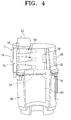
- FIG. 4 is a partial sectional view of the dust-collecting apparatus illustrated in FIG. 1 ;
- FIG. 5 is a sectional view of a first dust-collecting unit and a second dust-collecting unit of the dust-collecting apparatus taken along line V-V of FIG. 1 .
- a dust-collecting apparatus 10 may include a dust-collecting part 11 and a dust receptacle 80.
- the dust-collecting part 11 may draw in air laden with dust and separates the dust from the air.
- the dust receptacle 80 may temporarily store the dust separated by the dust-collecting part 11.
- "Dust" herein refers generally to dirt, dust, fine dust particles or the like, which are usually separated when cleaning a home, office, factory or other place.
- the dust-collecting part 11 and dust receptacle 80 can be attached to or separated from each other. As shown in FIG. 1 , the dust receptacle 80 can be joined to a bottom end of the dust-collecting part 11 while cleaning and can be separated from the dust-collecting part 11 when dumping the dust.
- the dust-collecting part 11 may include a first dust-collecting unit 20, a second dust-collecting unit 50, and a dust-collecting casing 12.
- the first and second dust-collecting units 20 and 50 may be arranged in series so that air can flow sequentially from the first dust-collecting unit 20 to the second dust-collecting unit 50. Additionally, the first and second dust-collecting units 20 and 50 may be cyclone dust-collecting units which swirl dust-laden air and separate dust from the air.
- An air inflow pipe 14 may project into an upper part of the dust-collecting casing 12.
- the air inflow pipe 14 may be installed tangentially to the cylindrical body 24, and accordingly the air can be drawn tangentially into the cylindrical body 24.
- An air inlet 22 may be formed in the air inflow pipe 14.
- a first opening 26 is formed on one side of the cylindrical body 24.
- An access member 28 is mounted on one side of the cylindrical body 24 so that it may be separated from the cylindrical body 24.
- the access member 28 may include a grip 29. If a user desires to clean the first dust-collecting chamber 23 and the filter member 21 mounted in the first dust-collecting chamber 23, the user can clasp the grip 29 and remove the access member 28 from the cylindrical body 24.
- the first dust-collecting unit 20 may be horizontally mounted.
- the first dust-collecting unit 20 may include a cylindrical body 24, and an access member 28.
- the first dust-collecting unit 20 may also include a first guide member 34, a second guide member 36, a third guide member 38, and a filter member 21.
- the cylindrical body 24 may be horizontally mounted in the dust-collecting casing 12.
- An air outlet 25 is formed on the other side of the cylindrical body 24.
- the guide members 34, 36 and 38 may be mounted in the first dust-collecting chamber 23.
- the first guide member 34 may prevent the air from being dispersed from the center of rotation and may also guide the air passing through the filter member 21 to the air outlet 25.
- the filter member 21 may be formed in the shape of a pipe.
- the second guide member 36 may be a spiral member which guides the air drawn in through the air inlet 22 so that the air rotates in the first dust-collecting chamber 23 on an outer circumference of the first guide member 34.
- the third guide member 38 may project from the access member 28.
- the third guide member 38 may be arranged opposite to the first guide member 34 in the first dust-collecting chamber 23.
- the third guide member 38 may be formed in the shape of a pipe in order to prevent the air from being dispersed from the center of rotation.
- the second dust-collecting unit 50 may be horizontally mounted in the first dust-collecting unit 20 similar to the first dust-collecting unit 20.
- the second dust-collecting unit 20 may include bodies 52 and a discharge pipe 56.
- the bodies 52 of the second dust-collecting units 50 may be horizontally arranged in a conical shape.
- Three bodies 52 of the second dust-collecting units 50 may be arranged at the left side of the body 24 of the first dust-collecting unit 20.
- Another three bodies 52 of the second dust-collecting units 50 may be arranged at the right side of the body 24 of the first dust-collecting unit 20.
- the length of the body 52 of the second dust-collecting unit 50 may be approximately half the length of the body 24 of the first dust-collecting unit 20. Accordingly, a dust discharge port 57 of the second dust-collecting unit 50 may be spaced away from the dust discharge port 32 of the first dust-collecting unit 20 at a predetermined distance.
- An air inlet 51 of the second dust-collecting unit 50 may be formed on one side of the body 52.
- the air inlet 51 may be in fluid communication with a first connection passage 70.
- a discharge pipe 56 may project into a second dust-collecting chamber 54.
- the second dust-collecting chamber 54 may be an internal space of the body 52.
- the second dust-collecting chamber 54 may be integrally formed with a second partition 75.
- Each of the second dust-collecting units 50 may draw in air discharged by the first dust-collecting unit 20 and may separate fine dust particles from the air.
- the number and shape of the second dust-collecting units 50 may be variously configured.
- the dust-collecting casing 12 may include a first partition 18 and the second partition 75 therein.
- the first partition 18 may divide the dust-collecting part 11 into a space in which the first dust-collecting unit 20 may be mounted and a space in which the second dust-collecting unit 50 may be mounted.
- the first partition 18 may have an "L" shape (shown in FIG. 3 ) so as to be connected to an inner circumference of the dust-collecting casing 12 and the outer circumference of the body 24 of the first dust-collecting unit 20. Accordingly, the first partition 18 may prevent mixing of dust discharged by the first dust-collecting unit 20 and dust separated by the second dust-collecting unit 50.
- the second partition 75 may be integrally formed with the discharge pipe 56 of the second dust-collecting unit 50.
- the second partition 75 may be connected to one side of the body 24 of the first dust-collecting unit 20 and the body 52 of the second dust-collecting unit 50. Therefore, the first connection passage 70 may be formed between the second partition 75 and the body 24 of the first dust-collecting unit 20.
- a second connection passage 72 may be formed between the second partition 75 and an outer wall 73 of the dust-collecting casing 12. The second connection passage 72 may be connected to a second opening 74 provided in the outer wall 73 of the dust-collecting casing 12.
- a dust discharge port 32 may be disposed substantially around the circumference of the body 24 of the first dust-collecting unit 20. Accordingly, the dust separated from the first dust-collecting chamber 23 may fall into the dust receptacle 80. Alternatively, the dust discharge port 32 may be formed around only a portion of the circumference of the body 24.
- the dust-collecting casing 12 may enclose the first dust-collecting unit 20 and the second dust-collecting unit 50.
- the dust-collecting casing 12 may be connected to or separated from the dust receptacle 80.
- a round case opening 19 having a cut interior may be formed on a bottom surface of the dust-collecting casing 12.
- the dust receptacle 80 may have a cylindrical shape.
- the dust receptacle 80 may include a third partition 82 therein.
- the third partition 82 may divide an internal space of the dust receptacle 80 into chambers 87, 88, and 89 so that dust dropping from the first dust-collecting unit 20 and dust dropping from the second dust-collecting unit 50 can be stored separately.
- a plurality of third partitions 82 may divide the internal space of the dust receptacle 80 into a first chamber 87, a second chamber 88 and a third chamber 89.
- FIGS. 1 to 5 a process for separating and collecting dust according to exemplary embodiments of the present invention will be described in detail with reference to FIGS. 1 to 5 .
- air laden with dust may be drawn in the first dust-collecting chamber 23 (shown in FIG. 2 ) through the air inflow pipe 14 (shown in FIG. 1 ).
- Large dust particles may be separated from the air while the air swirls along the guide members 34, 36 and 38, as indicated by arrow A in FIG. 2 .
- the separated dust may fall into the first chamber 87 of the dust receptacle 80 through the dust discharge port 32, as shown in FIG. 5 .
- the air may then pass through the filter member 21 to be dispersed into the second dust-collecting chambers 50 through the air outlet 25 and first connection passage 70, as indicated by arrow B in FIG. 2 .
- Fine dust particles may be discharged through the dust discharge port 57 while the air swirls from the second dust-collecting chambers 50, as indicated by arrow C in FIG. 2 .
- the discharged dust may fall into the second and third chambers 88 and 89 of the dust receptacle 80, as indicated by arrow E in FIG. 5 .
- the partitions 18 shown in FIG. 5 ), 75 (shown in FIG. 2 ) and 82 (shown in FIG. 5 ) prevent mixture of the dust discharged from the first and second dust-collecting chambers 23 and 54 (shown in FIG.
- the dust particles can be stored separately in the dust receptacle 80 (shown in FIG. 4 ).
- the air may then be discharged through the second dust-collecting chamber 54 to the outside of the dust-collecting apparatus 10 through the second connection passage 72 and second opening 74, as indicated by arrow D in FIG. 2 .
- the first dust-collecting unit and the second dust-collecting unit can be horizontally mounted, while the dust receptacle can be vertically mounted to prevent the dust collected in the dust receptacle from flowing back along the airflow. Additionally, the dust can be sequentially separated several times in two dust-collecting units which can be connected in series, and thus the dust-separating efficiency can be improved.
- the first dust-collecting unit can be disposed close to the second dust-collecting unit within the dust-collecting casing. Therefore, the dust-collecting apparatus can have a compact size. Also, the second dust-collecting unit can be horizontally mounted around the first dust-collecting unit to prolong the time until dumping of the dust in the dust receptacle is required.
Landscapes
- Engineering & Computer Science (AREA)
- Mechanical Engineering (AREA)
- Filters For Electric Vacuum Cleaners (AREA)
- Cyclones (AREA)
- Electric Suction Cleaners (AREA)
Abstract
Description
- The present invention relates to a vacuum cleaner. More particularly, the present invention relates to a dust-collecting apparatus for a vacuum cleaner.
- A conventional dust-collecting apparatus of a vacuum cleaner draws in air laden with dust and separates the dust from the air. The term "dust" will be used herein to refer collectively to dust, dirt, particulates, debris, contaminants, and other similar matter that can be entrained with the air suctioned by the vacuum cleaner. The conventional dust-collecting apparatus has become widely used because it can be used without the inconvenience of frequently replacing a dust bag.
- The conventional dust-collecting apparatus may typically comprise a filter through which air laden with dust passes to separate the dust from the air and a cyclone dust-collecting apparatus which whirls air laden with dust and separates the dust from the air using centrifugal force.
- As disclosed in Korean Patent Publication No.
412,583 - In addition,
US Patent Publication No. 6,350,292 discloses a cyclone dust-collecting apparatus, in which a dust-collecting unit and a dust receptacle are mounted at right angles so that air swirls and moves in a direction different from the direction in which dust falls in order to prevent the dust from flowing back. However, the dust-collecting apparatus has a large volume and the dust-separating efficiency is low. - An aspect of the present disclosure is to address at least the above problems and/or disadvantages and to provide at least the advantages described below. Accordingly, an aspect of the present disclosure is to provide a dust-collecting apparatus of a vacuum cleaner in which dust is prevented from flowing back, dust-collecting efficiency is improved, and capacity for holding dust is increased without increasing the volume of the dust-collecting apparatus.
- One embodiment of the present invention provides a dust-collecting apparatus of a vacuum cleaner. The dust-collecting apparatus of a vacuum cleaner includes a first dust-collecting unit which rotates air laden with dust and separates the dust from the air; a second dust-collecting unit which is mounted on one side of the first dust-collecting unit; and a dust receptacle which stores the dust separated by the first and the second dust-collecting units, the dust receptacle being mounted on a lower part of both the first and the second dust-collecting units, wherein at least one of the first and second dust-collecting units are substantially horizontally mounted, the dust receptacle is substantially vertically mounted relative to at least one of the first and second dust-collecting units , and the first and second dust-collecting units are arranged in series so that the air discharged from the first dust-collecting unit enters the second dust-collecting unit.
- Another embodiment of the present invention provides a dust-collecting apparatus of a vacuum cleaner. The dust-collecting apparatus of a vacuum cleaner includes first means for separating dust from air; second means for separating dust adapted to be disposed substantially horizontally relative to the first means for separating dust, the second means for separating dust being adapted to receive air from the first means for separating dust; and means for collecting the dust adapted to be disposed substantially vertically relative at least one of the first and the second means for separating dust.
- The dust-collecting apparatus of a vacuum cleaner includes a first means for whirling air to separate dust from air; a second means for whirling air adapted to be disposed substantially horizontally relative to the first means for whirling air, the second means for whirling air being adapted to receive air from the first means for whirling air; and a means for collecting the dust adapted to be disposed substantially vertically relative at least one of the first and second means for whirling.
- The above and/or other aspects of the present invention will be more apparent by describing certain exemplary embodiments of the present invention with reference to the accompanying drawings, in which:
-
FIG. 1 is a perspective view illustrating a dust-collecting apparatus of a vacuum cleaner, according to an embodiment of the present invention; -
FIG. 2 is a sectional view of the dust-collecting apparatus taken along line II-II ofFIG. 1 ; -
FIG. 3 is a perspective view of a dust-collecting part of the dust-collecting apparatus illustrated inFIG. 1 ; -
FIG. 4 is a partial sectional view of the dust-collecting apparatus illustrated inFIG. 1 ; and -
FIG. 5 is a sectional view of a first dust-collecting unit and a second dust-collecting unit of the dust-collecting apparatus taken along line V-V ofFIG. 1 . - Throughout the drawings, the same reference numerals will be understood to refer to the same elements, features, and structures.
- Hereinafter, a dust-collecting apparatus of a vacuum cleaner according to exemplary embodiments of the present invention will be described in detail with reference to the accompanying drawings.
- Referring to
FIG. 1 , a dust-collectingapparatus 10 may include a dust-collectingpart 11 and adust receptacle 80. The dust-collectingpart 11 may draw in air laden with dust and separates the dust from the air. Thedust receptacle 80 may temporarily store the dust separated by the dust-collectingpart 11. "Dust" herein refers generally to dirt, dust, fine dust particles or the like, which are usually separated when cleaning a home, office, factory or other place. The dust-collectingpart 11 anddust receptacle 80 can be attached to or separated from each other. As shown inFIG. 1 , thedust receptacle 80 can be joined to a bottom end of the dust-collectingpart 11 while cleaning and can be separated from the dust-collectingpart 11 when dumping the dust. - The dust-collecting
part 11 may include a first dust-collectingunit 20, a second dust-collectingunit 50, and a dust-collectingcasing 12. The first and second dust-collectingunits unit 20 to the second dust-collectingunit 50. Additionally, the first and second dust-collectingunits - An
air inflow pipe 14 may project into an upper part of the dust-collectingcasing 12. Theair inflow pipe 14 may be installed tangentially to thecylindrical body 24, and accordingly the air can be drawn tangentially into thecylindrical body 24. Anair inlet 22 may be formed in theair inflow pipe 14. Afirst opening 26 is formed on one side of thecylindrical body 24. - An
access member 28 is mounted on one side of thecylindrical body 24 so that it may be separated from thecylindrical body 24. Theaccess member 28 may include agrip 29. If a user desires to clean the first dust-collecting chamber 23 and thefilter member 21 mounted in the first dust-collecting chamber 23, the user can clasp thegrip 29 and remove theaccess member 28 from thecylindrical body 24. - The first dust-collecting
unit 20 may be horizontally mounted. The first dust-collecting unit 20 may include acylindrical body 24, and anaccess member 28. Referring toFIG. 2 , the first dust-collectingunit 20 may also include a first guide member 34, asecond guide member 36, athird guide member 38, and afilter member 21. Thecylindrical body 24 may be horizontally mounted in the dust-collectingcasing 12. Anair outlet 25 is formed on the other side of thecylindrical body 24. Theguide members collecting chamber 23. The first guide member 34 may prevent the air from being dispersed from the center of rotation and may also guide the air passing through thefilter member 21 to theair outlet 25. Thefilter member 21 may be formed in the shape of a pipe. Thesecond guide member 36 may be a spiral member which guides the air drawn in through theair inlet 22 so that the air rotates in the first dust-collectingchamber 23 on an outer circumference of the first guide member 34. Thethird guide member 38 may project from theaccess member 28. Thethird guide member 38 may be arranged opposite to the first guide member 34 in the first dust-collecting chamber 23. Also, thethird guide member 38 may be formed in the shape of a pipe in order to prevent the air from being dispersed from the center of rotation. - The second dust-collecting
unit 50 may be horizontally mounted in the first dust-collectingunit 20 similar to the first dust-collecting unit 20. The second dust-collectingunit 20 may includebodies 52 and adischarge pipe 56. Thebodies 52 of the second dust-collectingunits 50 may be horizontally arranged in a conical shape. Threebodies 52 of the second dust-collectingunits 50 may be arranged at the left side of thebody 24 of the first dust-collectingunit 20. Another threebodies 52 of the second dust-collectingunits 50 may be arranged at the right side of thebody 24 of the first dust-collectingunit 20. The length of thebody 52 of the second dust-collectingunit 50 may be approximately half the length of thebody 24 of the first dust-collectingunit 20. Accordingly, adust discharge port 57 of the second dust-collectingunit 50 may be spaced away from thedust discharge port 32 of the first dust-collectingunit 20 at a predetermined distance. - An
air inlet 51 of the second dust-collectingunit 50 may be formed on one side of thebody 52. Theair inlet 51 may be in fluid communication with afirst connection passage 70. Adischarge pipe 56 may project into a second dust-collectingchamber 54. The second dust-collectingchamber 54 may be an internal space of thebody 52. Also, the second dust-collectingchamber 54 may be integrally formed with asecond partition 75. Each of the second dust-collectingunits 50 may draw in air discharged by the first dust-collectingunit 20 and may separate fine dust particles from the air. The number and shape of the second dust-collectingunits 50 may be variously configured. - The dust-collecting
casing 12 may include afirst partition 18 and thesecond partition 75 therein. Thefirst partition 18 may divide the dust-collectingpart 11 into a space in which the first dust-collectingunit 20 may be mounted and a space in which the second dust-collectingunit 50 may be mounted. Thefirst partition 18 may have an "L" shape (shown inFIG. 3 ) so as to be connected to an inner circumference of the dust-collectingcasing 12 and the outer circumference of thebody 24 of the first dust-collectingunit 20. Accordingly, thefirst partition 18 may prevent mixing of dust discharged by the first dust-collectingunit 20 and dust separated by the second dust-collectingunit 50. Thesecond partition 75 may be integrally formed with thedischarge pipe 56 of the second dust-collectingunit 50. Thesecond partition 75 may be connected to one side of thebody 24 of the first dust-collectingunit 20 and thebody 52 of the second dust-collectingunit 50. Therefore, thefirst connection passage 70 may be formed between thesecond partition 75 and thebody 24 of the first dust-collectingunit 20. Asecond connection passage 72 may be formed between thesecond partition 75 and anouter wall 73 of the dust-collectingcasing 12. Thesecond connection passage 72 may be connected to asecond opening 74 provided in theouter wall 73 of the dust-collectingcasing 12. - Referring to
FIG. 3 , adust discharge port 32 may be disposed substantially around the circumference of thebody 24 of the first dust-collectingunit 20. Accordingly, the dust separated from the first dust-collectingchamber 23 may fall into thedust receptacle 80. Alternatively, thedust discharge port 32 may be formed around only a portion of the circumference of thebody 24. - The dust-collecting
casing 12 may enclose the first dust-collectingunit 20 and the second dust-collectingunit 50. The dust-collectingcasing 12 may be connected to or separated from thedust receptacle 80. Around case opening 19 having a cut interior may be formed on a bottom surface of the dust-collectingcasing 12. - Referring to
FIG. 4 , thedust receptacle 80 may have a cylindrical shape. Thedust receptacle 80 may include athird partition 82 therein. Referring toFIG. 5 , thethird partition 82 may divide an internal space of thedust receptacle 80 intochambers unit 20 and dust dropping from the second dust-collectingunit 50 can be stored separately. For example, a plurality ofthird partitions 82 may divide the internal space of thedust receptacle 80 into afirst chamber 87, asecond chamber 88 and athird chamber 89. - Hereinafter, a process for separating and collecting dust according to exemplary embodiments of the present invention will be described in detail with reference to
FIGS. 1 to 5 . In this process, air laden with dust may be drawn in the first dust-collecting chamber 23 (shown inFIG. 2 ) through the air inflow pipe 14 (shown inFIG. 1 ). Large dust particles may be separated from the air while the air swirls along theguide members FIG. 2 . The separated dust may fall into thefirst chamber 87 of thedust receptacle 80 through thedust discharge port 32, as shown inFIG. 5 . The air may then pass through thefilter member 21 to be dispersed into the second dust-collectingchambers 50 through theair outlet 25 andfirst connection passage 70, as indicated by arrow B inFIG. 2 . Fine dust particles may be discharged through thedust discharge port 57 while the air swirls from the second dust-collectingchambers 50, as indicated by arrow C inFIG. 2 . The discharged dust may fall into the second andthird chambers dust receptacle 80, as indicated by arrow E inFIG. 5 . The partitions 18 (shown inFIG. 5 ), 75 (shown inFIG. 2 ) and 82 (shown inFIG. 5 ) prevent mixture of the dust discharged from the first and second dust-collectingchambers 23 and 54 (shown inFIG. 2 ). Thus, the dust particles can be stored separately in the dust receptacle 80 (shown inFIG. 4 ). The air may then be discharged through the second dust-collectingchamber 54 to the outside of the dust-collectingapparatus 10 through thesecond connection passage 72 andsecond opening 74, as indicated by arrow D inFIG. 2 . - In the dust-collecting apparatus of the vacuum cleaner according to the exemplary embodiment of the present invention, the first dust-collecting unit and the second dust-collecting unit can be horizontally mounted, while the dust receptacle can be vertically mounted to prevent the dust collected in the dust receptacle from flowing back along the airflow. Additionally, the dust can be sequentially separated several times in two dust-collecting units which can be connected in series, and thus the dust-separating efficiency can be improved.
- Furthermore, in the dust-collecting apparatus of the vacuum cleaner according to the exemplary embodiment of the present invention, the first dust-collecting unit can be disposed close to the second dust-collecting unit within the dust-collecting casing. Therefore, the dust-collecting apparatus can have a compact size. Also, the second dust-collecting unit can be horizontally mounted around the first dust-collecting unit to prolong the time until dumping of the dust in the dust receptacle is required.
Claims (14)
- A dust-collecting apparatus of a vacuum cleaner, comprising:a first dust-collecting unit which rotates air laden with dust and separates the dust from the air;a second dust-collecting unit which is mounted on one side of the first dust-collecting unit; anda dust receptacle which stores the dust separated by the first and the second dust-collecting units, the dust receptacle being mounted on a lower part of both the first and the second dust-collecting units,wherein at least one of the first and second dust-collecting units are substantially horizontally mounted, the dust receptacle is substantially vertically mounted relative to at least one of the first and second dust-collecting units , and the first and second dust-collecting units are arranged in series so that the air discharged from the first dust-collecting unit enters the second dust-collecting unit.
- The apparatus as claimed in claim 1, wherein the first and second dust-collecting units are cyclone dust-collecting units which swirl dust-laden air and separate dust from the air.
- The apparatus as claimed in any of claims 1 and 2, wherein a plurality of second dust-collecting units are mounted around the first dust-collecting unit.
- The apparatus as claimed in any of claims 1 to 3, wherein the first dust-collecting unit has a cylindrical shape, and the second dust-collecting unit has a conical shape.
- The apparatus as claimed in any of claims 1 to 4, further comprising a dust-collecting casing which encloses the first and second dust-collecting units.
- The apparatus as claimed in claim 5, wherein the dust-collecting casing comprises a case opening on a bottom surface thereof, and the dust receptacle is detachably connected to the bottom surface of the dust-collecting casing.
- The apparatus as claimed in any of claims 1 to 6, wherein an air inlet, an air inflow pipe, and a dust discharge port are formed in the first dust-collecting unit, and
the first dust-collecting unit comprises:a cylindrical body in which a first dust-collecting chamber is formed; andan openable closure member which is detachably mounted at one end of the cylindrical body, the openable closure member being capable of opening or closing one side of the first dust-collecting chamber. - The apparatus as claimed in claim 7, wherein the air inlet is formed on a tangent to the cylindrical body, and the dust discharge port is formed around a circumference of the cylindrical body.
- The apparatus as claimed in any of claims 7 and 8, further comprising in the first dust-collecting chamber at least one guide member which guides the rotation of the air.
- The apparatus as claimed in any of claims 5 to 9, wherein the dust-collecting casing comprises at least one partition which allows the first dust-collecting unit and the second dust-collecting unit to be spatially divided.
- The apparatus as claimed in any of claims 1 to 10, wherein the dust receptacle comprises partitions which divide an internal space of the dust receptacle into spaces which store dust separated by the first and the second dust-collecting units.
- A dust-collecting apparatus of a vacuum cleaner, comprising:first means for separating dust from air;second means for separating dust adapted to be disposed substantially horizontally relative to the first means for separating dust, the second means for separating dust being adapted to receive air from the first means for separating dust; andmeans for collecting the dust, adapted to be disposed substantially vertically relative at least one of the first and the second means for separating dust.
- The dust-collecting apparatus of claim 12, wherein the second means for separating dust includes a plurality of second means for separating dust adapted to be disposed substantially horizontally relative to the first means for separating dust.
- The dust-collecting apparatus of any of claims 12 and 13, wherein the first means for separating dust comprises:first means for collecting dust;means for accessing the first means for collecting dust adapted to be disposed at the first means for collecting dust;means for receiving air adapted to be in fluid communication with the first means for collecting dust; andmeans for discharging dust adapted to be in fluid communication with the first means for collecting dust.
Applications Claiming Priority (1)
| Application Number | Priority Date | Filing Date | Title |
|---|---|---|---|
| KR1020070011674A KR100776404B1 (en) | 2007-02-05 | 2007-02-05 | Dust collector of vacuum cleaner |
Publications (2)
| Publication Number | Publication Date |
|---|---|
| EP1952745A2 true EP1952745A2 (en) | 2008-08-06 |
| EP1952745A3 EP1952745A3 (en) | 2009-07-29 |
Family
ID=39079769
Family Applications (1)
| Application Number | Title | Priority Date | Filing Date |
|---|---|---|---|
| EP07291187A Withdrawn EP1952745A3 (en) | 2007-02-05 | 2007-10-01 | Dust-collecting apparatus of a vacuum cleaner |
Country Status (6)
| Country | Link |
|---|---|
| US (1) | US7789923B2 (en) |
| EP (1) | EP1952745A3 (en) |
| KR (1) | KR100776404B1 (en) |
| AU (1) | AU2007219290B2 (en) |
| CA (1) | CA2601615C (en) |
| RU (1) | RU2362474C2 (en) |
Cited By (4)
| Publication number | Priority date | Publication date | Assignee | Title |
|---|---|---|---|---|
| GB2456603A (en) * | 2008-01-16 | 2009-07-22 | Samsung Kwangju Electronics Co | Cyclonic Dust-Separating Apparatus |
| EP2090211A4 (en) * | 2007-03-08 | 2010-02-03 | Kingclean Electric Co Ltd | A dust separating device of a cleaner |
| WO2012113840A1 (en) | 2011-02-22 | 2012-08-30 | Aktiebolaget Electrolux | Vacuum cleaner |
| WO2013123985A1 (en) | 2012-02-22 | 2013-08-29 | Aktiebolaget Electrolux | Vacuum cleaner filter assembly and vacuum cleaner |
Families Citing this family (7)
| Publication number | Priority date | Publication date | Assignee | Title |
|---|---|---|---|---|
| US7951218B2 (en) * | 2009-02-16 | 2011-05-31 | Samsung Gwangju Electronics Co., Ltd. | Dust separating apparatus of vacuum cleaner |
| US10631697B2 (en) * | 2014-02-14 | 2020-04-28 | Techtronic Industries Co. Ltd. | Separator configuration |
| WO2016065146A1 (en) | 2014-10-22 | 2016-04-28 | Techtronic Industries Co. Ltd. | Vacuum cleaner having cyclonic separator |
| WO2016065148A2 (en) | 2014-10-22 | 2016-04-28 | Techtronic Industries Co. Ltd. | Vacuum cleaner having cyclonic separator |
| EP3209175B1 (en) | 2014-10-22 | 2023-01-04 | Techtronic Industries Co. Ltd. | Handheld vacuum cleaner |
| USD1048618S1 (en) * | 2017-03-21 | 2024-10-22 | Faster Better Easier, Llc | Dust separator |
| USD1063268S1 (en) * | 2023-03-06 | 2025-02-18 | Samsung Electronics Co., Ltd. | Vacuum cleaner |
Family Cites Families (17)
| Publication number | Priority date | Publication date | Assignee | Title |
|---|---|---|---|---|
| US2424572A (en) * | 1945-06-11 | 1947-07-29 | B F Sturtevant Co | Dust collector |
| JPS59130559A (en) | 1983-01-13 | 1984-07-27 | Fuji Electric Corp Res & Dev Ltd | Cyclone dust collector |
| SE9901252L (en) | 1999-04-08 | 2000-02-28 | Electrolux Ab | Drainage system for a cyclone vacuum cleaner |
| GB2344778A (en) | 1998-12-18 | 2000-06-21 | Notetry Ltd | Cyclonic separator and fan combination |
| KR100510644B1 (en) * | 2000-02-17 | 2005-08-31 | 엘지전자 주식회사 | cyclone dust collector |
| JP3930737B2 (en) * | 2000-02-19 | 2007-06-13 | エルジー エレクトロニクス インコーポレーテッド | Multiple cyclone vacuum cleaner |
| KR20020071625A (en) | 2001-03-07 | 2002-09-13 | 엘지전자주식회사 | Multi cyclone dust collector |
| KR20020071622A (en) | 2001-03-07 | 2002-09-13 | 엘지전자주식회사 | Multi cyclone dust collector |
| JP2004121722A (en) | 2002-10-07 | 2004-04-22 | Sanyo Electric Co Ltd | Dust collector and vacuum cleaner using the same |
| GB0228148D0 (en) | 2002-12-03 | 2003-01-08 | Techtronic Ind Co Ltd | Dust separator and collector arrangement for suction cleaner |
| KR100533830B1 (en) | 2004-05-14 | 2005-12-07 | 삼성광주전자 주식회사 | Multi cyclone dust collecting apparatus |
| KR20050119740A (en) * | 2004-06-17 | 2005-12-22 | 엘지전자 주식회사 | A dust collector for vacuum cleaner |
| KR100622549B1 (en) | 2004-11-25 | 2006-09-19 | 삼성광주전자 주식회사 | Multi Cyclone Dust Collector |
| FR2882912B1 (en) * | 2005-03-14 | 2007-06-08 | Claude Brenot | INTEGRAL SOIL CLEANER |
| KR100662635B1 (en) * | 2005-06-14 | 2007-01-02 | 삼성광주전자 주식회사 | Cyclone Dust Collector of Vacuum Cleaner |
| KR100629601B1 (en) | 2005-09-16 | 2006-09-27 | 엘지전자 주식회사 | Dust collector for vacuum cleaner |
| US7882592B2 (en) * | 2005-12-10 | 2011-02-08 | Lg Electronics Inc. | Vacuum cleaner |
-
2007
- 2007-02-05 KR KR1020070011674A patent/KR100776404B1/en not_active Expired - Fee Related
- 2007-07-31 US US11/882,268 patent/US7789923B2/en not_active Expired - Fee Related
- 2007-09-13 CA CA2601615A patent/CA2601615C/en not_active Expired - Fee Related
- 2007-09-25 AU AU2007219290A patent/AU2007219290B2/en not_active Ceased
- 2007-10-01 EP EP07291187A patent/EP1952745A3/en not_active Withdrawn
- 2007-10-02 RU RU2007136188/12A patent/RU2362474C2/en not_active IP Right Cessation
Cited By (8)
| Publication number | Priority date | Publication date | Assignee | Title |
|---|---|---|---|---|
| EP2090211A4 (en) * | 2007-03-08 | 2010-02-03 | Kingclean Electric Co Ltd | A dust separating device of a cleaner |
| GB2456603A (en) * | 2008-01-16 | 2009-07-22 | Samsung Kwangju Electronics Co | Cyclonic Dust-Separating Apparatus |
| GB2456603B (en) * | 2008-01-16 | 2010-02-10 | Samsung Kwangju Electronics Co | Cyclonic dust-separating apparatus |
| US7981181B2 (en) | 2008-01-16 | 2011-07-19 | Samsung Gwangju Electronics Co., Ltd. | Cyclone dust-separating apparatus and cleaner having the same |
| WO2012113840A1 (en) | 2011-02-22 | 2012-08-30 | Aktiebolaget Electrolux | Vacuum cleaner |
| WO2012113821A1 (en) | 2011-02-22 | 2012-08-30 | Aktiebolaget Electrolux | Vacuum cleaner dust container and a vacuum cleaner |
| WO2012113839A1 (en) | 2011-02-22 | 2012-08-30 | Aktiebolaget Electrolux | Vacuum cleaner |
| WO2013123985A1 (en) | 2012-02-22 | 2013-08-29 | Aktiebolaget Electrolux | Vacuum cleaner filter assembly and vacuum cleaner |
Also Published As
| Publication number | Publication date |
|---|---|
| CA2601615A1 (en) | 2008-08-05 |
| RU2362474C2 (en) | 2009-07-27 |
| RU2007136188A (en) | 2009-04-10 |
| AU2007219290B2 (en) | 2009-12-10 |
| US7789923B2 (en) | 2010-09-07 |
| EP1952745A3 (en) | 2009-07-29 |
| AU2007219290A1 (en) | 2008-08-21 |
| CA2601615C (en) | 2010-11-23 |
| US20080184680A1 (en) | 2008-08-07 |
| KR100776404B1 (en) | 2007-11-16 |
Similar Documents
| Publication | Publication Date | Title |
|---|---|---|
| CA2601615C (en) | Dust-collecting apparatus of a vacuum cleaner | |
| US7628833B2 (en) | Multi-cyclone dust separating apparatus | |
| KR100866354B1 (en) | Vacuum cleaner | |
| US7749296B2 (en) | Cyclone dust-separating apparatus of vacuum cleaner | |
| US7717973B2 (en) | Cyclone dust-separating apparatus of vacuum cleaner | |
| EP1772090B1 (en) | Multi-cyclone dust collection apparatus | |
| US7501002B2 (en) | Cyclone dust separator and a vacuum cleaner having the same | |
| EP1721556B1 (en) | Multi-cyclone apparatus and vacuum cleaner having the same | |
| US7326268B2 (en) | Multi cyclone vessel dust collecting apparatus for vacuum cleaner | |
| CN101288574B (en) | Cyclone dust separator for vacuum cleaners | |
| US20070011998A1 (en) | Dust collecting apparatus for vacuum cleaner | |
| JP2004529682A (en) | Cyclone type separation device | |
| GB2402092A (en) | Dual cyclone for a vacuum cleaner | |
| AU2017423525B2 (en) | Vacuum cleaner | |
| US10028630B2 (en) | Cleaner | |
| CN101282674B (en) | Dust collection device for vacuum cleaner | |
| CN101970078A (en) | Two-stage cyclone dust collector | |
| KR20080066291A (en) | Dust collection unit of the vacuum cleaner | |
| KR100556443B1 (en) | Dust collector of vacuum cleaner | |
| KR20070032098A (en) | Dust collector for vacuum cleaner |
Legal Events
| Date | Code | Title | Description |
|---|---|---|---|
| PUAI | Public reference made under article 153(3) epc to a published international application that has entered the european phase |
Free format text: ORIGINAL CODE: 0009012 |
|
| AK | Designated contracting states |
Kind code of ref document: A2 Designated state(s): AT BE BG CH CY CZ DE DK EE ES FI FR GB GR HU IE IS IT LI LT LU LV MC MT NL PL PT RO SE SI SK TR |
|
| AX | Request for extension of the european patent |
Extension state: AL BA HR MK RS |
|
| PUAL | Search report despatched |
Free format text: ORIGINAL CODE: 0009013 |
|
| AK | Designated contracting states |
Kind code of ref document: A3 Designated state(s): AT BE BG CH CY CZ DE DK EE ES FI FR GB GR HU IE IS IT LI LT LU LV MC MT NL PL PT RO SE SI SK TR |
|
| AX | Request for extension of the european patent |
Extension state: AL BA HR MK RS |
|
| 17P | Request for examination filed |
Effective date: 20091104 |
|
| AKX | Designation fees paid |
Designated state(s): DE FR GB IT |
|
| RAP1 | Party data changed (applicant data changed or rights of an application transferred) |
Owner name: SAMSUNG ELECTRONICS CO., LTD. |
|
| RAP1 | Party data changed (applicant data changed or rights of an application transferred) |
Owner name: SAMSUNG ELECTRONICS CO., LTD. |
|
| STAA | Information on the status of an ep patent application or granted ep patent |
Free format text: STATUS: THE APPLICATION IS DEEMED TO BE WITHDRAWN |
|
| 18D | Application deemed to be withdrawn |
Effective date: 20160503 |