EP1952017B1 - A method for damping tower vibrations in a wind turbine installation - Google Patents
A method for damping tower vibrations in a wind turbine installation Download PDFInfo
- Publication number
- EP1952017B1 EP1952017B1 EP06812802.4A EP06812802A EP1952017B1 EP 1952017 B1 EP1952017 B1 EP 1952017B1 EP 06812802 A EP06812802 A EP 06812802A EP 1952017 B1 EP1952017 B1 EP 1952017B1
- Authority
- EP
- European Patent Office
- Prior art keywords
- tower
- blade angle
- eig
- stabiliser
- stab
- Prior art date
- Legal status (The legal status is an assumption and is not a legal conclusion. Google has not performed a legal analysis and makes no representation as to the accuracy of the status listed.)
- Active
Links
Images


Classifications
-
- F—MECHANICAL ENGINEERING; LIGHTING; HEATING; WEAPONS; BLASTING
- F03—MACHINES OR ENGINES FOR LIQUIDS; WIND, SPRING, OR WEIGHT MOTORS; PRODUCING MECHANICAL POWER OR A REACTIVE PROPULSIVE THRUST, NOT OTHERWISE PROVIDED FOR
- F03D—WIND MOTORS
- F03D7/00—Controlling wind motors
- F03D7/02—Controlling wind motors the wind motors having rotation axis substantially parallel to the air flow entering the rotor
- F03D7/0296—Controlling wind motors the wind motors having rotation axis substantially parallel to the air flow entering the rotor to prevent, counteract or reduce noise emissions
-
- B—PERFORMING OPERATIONS; TRANSPORTING
- B63—SHIPS OR OTHER WATERBORNE VESSELS; RELATED EQUIPMENT
- B63B—SHIPS OR OTHER WATERBORNE VESSELS; EQUIPMENT FOR SHIPPING
- B63B39/00—Equipment to decrease pitch, roll, or like unwanted vessel movements; Apparatus for indicating vessel attitude
-
- F—MECHANICAL ENGINEERING; LIGHTING; HEATING; WEAPONS; BLASTING
- F03—MACHINES OR ENGINES FOR LIQUIDS; WIND, SPRING, OR WEIGHT MOTORS; PRODUCING MECHANICAL POWER OR A REACTIVE PROPULSIVE THRUST, NOT OTHERWISE PROVIDED FOR
- F03D—WIND MOTORS
- F03D7/00—Controlling wind motors
- F03D7/02—Controlling wind motors the wind motors having rotation axis substantially parallel to the air flow entering the rotor
- F03D7/022—Adjusting aerodynamic properties of the blades
- F03D7/024—Adjusting aerodynamic properties of the blades of individual blades
-
- F—MECHANICAL ENGINEERING; LIGHTING; HEATING; WEAPONS; BLASTING
- F03—MACHINES OR ENGINES FOR LIQUIDS; WIND, SPRING, OR WEIGHT MOTORS; PRODUCING MECHANICAL POWER OR A REACTIVE PROPULSIVE THRUST, NOT OTHERWISE PROVIDED FOR
- F03D—WIND MOTORS
- F03D7/00—Controlling wind motors
- F03D7/02—Controlling wind motors the wind motors having rotation axis substantially parallel to the air flow entering the rotor
- F03D7/04—Automatic control; Regulation
- F03D7/042—Automatic control; Regulation by means of an electrical or electronic controller
- F03D7/043—Automatic control; Regulation by means of an electrical or electronic controller characterised by the type of control logic
- F03D7/044—Automatic control; Regulation by means of an electrical or electronic controller characterised by the type of control logic with PID control
-
- F—MECHANICAL ENGINEERING; LIGHTING; HEATING; WEAPONS; BLASTING
- F03—MACHINES OR ENGINES FOR LIQUIDS; WIND, SPRING, OR WEIGHT MOTORS; PRODUCING MECHANICAL POWER OR A REACTIVE PROPULSIVE THRUST, NOT OTHERWISE PROVIDED FOR
- F03D—WIND MOTORS
- F03D9/00—Adaptations of wind motors for special use; Combinations of wind motors with apparatus driven thereby; Wind motors specially adapted for installation in particular locations
- F03D9/20—Wind motors characterised by the driven apparatus
- F03D9/25—Wind motors characterised by the driven apparatus the apparatus being an electrical generator
-
- F—MECHANICAL ENGINEERING; LIGHTING; HEATING; WEAPONS; BLASTING
- F03—MACHINES OR ENGINES FOR LIQUIDS; WIND, SPRING, OR WEIGHT MOTORS; PRODUCING MECHANICAL POWER OR A REACTIVE PROPULSIVE THRUST, NOT OTHERWISE PROVIDED FOR
- F03D—WIND MOTORS
- F03D9/00—Adaptations of wind motors for special use; Combinations of wind motors with apparatus driven thereby; Wind motors specially adapted for installation in particular locations
- F03D9/20—Wind motors characterised by the driven apparatus
- F03D9/25—Wind motors characterised by the driven apparatus the apparatus being an electrical generator
- F03D9/255—Wind motors characterised by the driven apparatus the apparatus being an electrical generator connected to electrical distribution networks; Arrangements therefor
-
- F—MECHANICAL ENGINEERING; LIGHTING; HEATING; WEAPONS; BLASTING
- F03—MACHINES OR ENGINES FOR LIQUIDS; WIND, SPRING, OR WEIGHT MOTORS; PRODUCING MECHANICAL POWER OR A REACTIVE PROPULSIVE THRUST, NOT OTHERWISE PROVIDED FOR
- F03D—WIND MOTORS
- F03D13/00—Assembly, mounting or commissioning of wind motors; Arrangements specially adapted for transporting wind motor components
- F03D13/20—Arrangements for mounting or supporting wind motors; Masts or towers for wind motors
- F03D13/25—Arrangements for mounting or supporting wind motors; Masts or towers for wind motors specially adapted for offshore installation
-
- F—MECHANICAL ENGINEERING; LIGHTING; HEATING; WEAPONS; BLASTING
- F03—MACHINES OR ENGINES FOR LIQUIDS; WIND, SPRING, OR WEIGHT MOTORS; PRODUCING MECHANICAL POWER OR A REACTIVE PROPULSIVE THRUST, NOT OTHERWISE PROVIDED FOR
- F03D—WIND MOTORS
- F03D7/00—Controlling wind motors
- F03D7/02—Controlling wind motors the wind motors having rotation axis substantially parallel to the air flow entering the rotor
- F03D7/022—Adjusting aerodynamic properties of the blades
- F03D7/0224—Adjusting blade pitch
-
- F—MECHANICAL ENGINEERING; LIGHTING; HEATING; WEAPONS; BLASTING
- F05—INDEXING SCHEMES RELATING TO ENGINES OR PUMPS IN VARIOUS SUBCLASSES OF CLASSES F01-F04
- F05B—INDEXING SCHEME RELATING TO WIND, SPRING, WEIGHT, INERTIA OR LIKE MOTORS, TO MACHINES OR ENGINES FOR LIQUIDS COVERED BY SUBCLASSES F03B, F03D AND F03G
- F05B2240/00—Components
- F05B2240/90—Mounting on supporting structures or systems
- F05B2240/93—Mounting on supporting structures or systems on a structure floating on a liquid surface
-
- F—MECHANICAL ENGINEERING; LIGHTING; HEATING; WEAPONS; BLASTING
- F05—INDEXING SCHEMES RELATING TO ENGINES OR PUMPS IN VARIOUS SUBCLASSES OF CLASSES F01-F04
- F05B—INDEXING SCHEME RELATING TO WIND, SPRING, WEIGHT, INERTIA OR LIKE MOTORS, TO MACHINES OR ENGINES FOR LIQUIDS COVERED BY SUBCLASSES F03B, F03D AND F03G
- F05B2260/00—Function
- F05B2260/96—Preventing, counteracting or reducing vibration or noise
-
- Y—GENERAL TAGGING OF NEW TECHNOLOGICAL DEVELOPMENTS; GENERAL TAGGING OF CROSS-SECTIONAL TECHNOLOGIES SPANNING OVER SEVERAL SECTIONS OF THE IPC; TECHNICAL SUBJECTS COVERED BY FORMER USPC CROSS-REFERENCE ART COLLECTIONS [XRACs] AND DIGESTS
- Y02—TECHNOLOGIES OR APPLICATIONS FOR MITIGATION OR ADAPTATION AGAINST CLIMATE CHANGE
- Y02E—REDUCTION OF GREENHOUSE GAS [GHG] EMISSIONS, RELATED TO ENERGY GENERATION, TRANSMISSION OR DISTRIBUTION
- Y02E10/00—Energy generation through renewable energy sources
- Y02E10/70—Wind energy
- Y02E10/72—Wind turbines with rotation axis in wind direction
-
- Y—GENERAL TAGGING OF NEW TECHNOLOGICAL DEVELOPMENTS; GENERAL TAGGING OF CROSS-SECTIONAL TECHNOLOGIES SPANNING OVER SEVERAL SECTIONS OF THE IPC; TECHNICAL SUBJECTS COVERED BY FORMER USPC CROSS-REFERENCE ART COLLECTIONS [XRACs] AND DIGESTS
- Y02—TECHNOLOGIES OR APPLICATIONS FOR MITIGATION OR ADAPTATION AGAINST CLIMATE CHANGE
- Y02E—REDUCTION OF GREENHOUSE GAS [GHG] EMISSIONS, RELATED TO ENERGY GENERATION, TRANSMISSION OR DISTRIBUTION
- Y02E10/00—Energy generation through renewable energy sources
- Y02E10/70—Wind energy
- Y02E10/727—Offshore wind turbines
Definitions
- the present method is a method for damping tower vibrations in a floating wind turbine installation.
- the wind turbine installation comprises a floating cell, a tower arranged over the floating cell, a generator mounted on the tower that is rotatable in relation to the wind direction and fitted with a wind turbine, and an anchor line arrangement that is connectable to anchors or foundations on the sea bed.
- a wind turbine that is mounted on a floating foundation will move on account of the forces from the wind and waves.
- a good wind turbine foundation design will ensure that the system's eigenperiods for rigid cell movements (surge, sway, heave, roll, pitch and yaw) are outside the period range for sea waves, which is approximately 5 - 20 seconds.
- US 4420692 discloses a fixed foundation wind turbine with an acceleratometer disposed on the support tower which provides a signal indicative of acceleration of the tower in the direction of the rotor rotational axis.
- the signal is passed through a band-pass filter for summation with a torque/power controlled blade pitch angle reference rate signal, thereby to provide additional, positive aerodynamic damping to the tower.
- WO02/075153 relates to a method for controlling a wind power installation comprising a control device for the operational management of the wind power installation by which the acceleration of the tower is measured.
- the present invention represents a solution, more precisely a method and a blade angle controller, for effective damping of tower vibrations for wind turbine installations.
- the results produced in simulation tests show that vibrations in connection with the system's eigenperiod were damped by a factor of approximately 10 using the method in accordance with the present invention.
- the present invention provides a method for damping tower vibrations in a floating wind turbine installation, the installation comprising a floating cell, a tower arranged over the floating cell, a generator mounted on the tower that is rotatable in relation to the wind direction and fitted with a wind turbine comprising turbine blades, and an anchor line arrangement that is connectable to anchors or foundations on a sea bed; wherein the method comprises: controlling the generator in response to changes in the relative wind velocity against the turbine, by controlling the blade angle of the turbine blades by means of a controller in the constant power or RPM range of the wind turbine; and damping the tower's eigenvibrations by, in addition to controlling the controller in the constant power or RPM range of the wind turbine, an increment being added to the blade angle of the turbine blades on the basis of the tower velocities, so that the eigenvibrations of the tower are counteracted; wherein the vibrations in the horizontal displacement of the top of the tower that have the frequency of the tower's eigenvibrations are damped
- the present invention provides a blade angle controller for controlling the blade angle of turbine blades on a floating wind turbine installation, the installation comprising a floating cell, a tower arranged over the floating cell, a generator mounted on the tower that is rotatable in relation to the wind direction and fitted with a wind turbine comprising turbine blades, and an anchor line arrangement that is connectable to anchors or foundations on a sea bed; wherein the blade angle controller is adapted to control the generator in response to changes in the relative wind velocity against the turbine, by controlling the blade angle of the turbine blades in the constant power or RPM range of the wind turbine; and to damp the tower's eigenvibrations by, in addition to controlling the blade angle of the turbine blades in the constant power or RPM range of the wind turbine, an increment being added to the blade angle of the turbine blades on the basis of the tower velocities so that the eigenvibrations of the tower are counteracted; wherein the vibrations in the horizontal displacement of the top of the tower that have the frequency of the tower's
- control algorithms must be modified to prevent the negative link between control of the wind turbines and the system's movements.
- Fig. 2 shows a section of a blade angle controller, with proportional and integral control (PI), and a sketch of the transfer function.
- PI proportional and integral control
- H ⁇ - ⁇ Z8 dot (s) between the blade angle, ⁇ , and the horizontal tower velocity. This is the change required in the turbine blade angle to maintain constant power on the turbine when the relative velocity changes.
- H stab j ⁇ ⁇ eig - b K ⁇ e - j ⁇ where "b" is a variable control amplifier. This is selected on the basis of obtaining best possible damping of the tower ocillations and at the same time avoiding unwanted exitation of other eigenfrequncis depending on the turbine blade momentum and thrust characteristic.
- Fig. 3 shows an example of the transfer function between the blade angle and the tower velocity as well as the transfer function for a stabiliser that damps vibrations with the eigenfrequency of the tower vibrations.
- H ls ( s ) is the transfer function for the closed loop, including the stabiliser, from ⁇ 0 to ⁇ .
- any stabiliser designed according to the criteria in (2.3) that will reduce the tower vibrations will not necessarily supply the system with enough damping to make it stable. Therefore, in addition, it is necessary to demand that the system is stable when selecting the controller parameters for the turbine in question.
- ⁇ eig An example was based on the tower vibrations' eigenfrequency, ⁇ eig , being approximately equal to 0.5 radians/second ( f eig ⁇ 0.0795 Hz), i.e. on a vibration of the tower having a period of approximately 12.57 s.
- the stabiliser in accordance with the present invention which was created to damp the tower vibrations that vibrate with the eigenfrequency, then had a transfer function as shown in Fig. 4 .
- FIG. 5 A Bode plot of this transfer function is shown in Fig. 5 .
- the Figure shows the frequency response of the designed stabiliser.
- the arrows define amplitude and phase in connection with the eigenfrequency of the tower dynamics.
- the stabiliser solution is included in the control solution in accordance with the present invention, and the Figure shows how the output signal from the stabiliser is designed to modulate the turbine's blade angle, ⁇ .
- the principle of the solution in accordance with the present invention is thus to damp the tower's eigenvibrations by controlling the blade angle of the turbine blades so that the eigenvibrations are counteracted.
- the stabiliser is designed so that it only has to affect the blade angle in the frequency range near the tower vibrations' eigenfrequency, ⁇ eig ..
- a high-pass filter ensures that no (zero) amplification is provided at low frequencies, and a low-pass filter ensures that no (zero) amplification is provided at high frequencies.
- a phase-compensating filter must be tuned so that the phase distortion in the stabiliser is such that additional damping, ⁇ (+ or -), damps the vibrations in ⁇ Z that are caused by the tower vibrations' eigenfrequency, w eig. .
- this means that the blade angle is affected by an amplitude and phase in relation to the tower's velocity ⁇ Z in such a way that it damps the vibrations in the tower that have frequency ⁇ eig .
- the stabiliser leads to the turbine experiencing a relative wind velocity with greatly reduced influence from the tower's eigenvibrations in relation to a situation in which the stabiliser is not used. In addition, the tower will physically vibrate much less when a stabiliser is used.
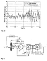
- Figs. 7 and 8 show a selection of results from the simulation of wind series at 17.43 m/sec. with and without stabilisers for damping tower vibrations.
- Fig. 7 shows that there are considerable tower vibrations when the turbine runs in constant power mode and the stabiliser is not used. This also results in large fluctuations in power supplied to the grid (see Fig. 8 ).
- the high amplitudes in the tower vibrations can be explained as follows:
- Fig. 7 shows that the tower vibrations are damped well, and Fig. 8 shows that the power variation is also considerably reduced.
- the stabiliser thus produces the desired effect.
- the amplitude of the tower vibrations is reduced from over 10 m without a stabiliser to under 1 m with a stabiliser.
- Fig. 9 and Fig. 10 show the results for the case with 20.04 m/sec. wind velocity. It can be seen that the turbine supplies approximately constant power without a stabiliser, Fig. 9 , but that the tower vibrations gradually build up to large fluctuations, Fig. 10 . If a stabiliser is used, the power remains approximately constant, while a considerable reduction in the tower movement is achieved.
- Fig. 11 shows a general diagram of a wind turbine including the stabiliser in accordance with the present invention.
- the stabiliser acts by receiving the signal associated with the change in tower velocity, ⁇ Z , from a sensor (not shown) in the form of an accelerometer or similar.
- the signal is "processed" by the stabiliser, which emits a new signal to a controller for the rotor blades to change the pitch angle, ⁇ , of the blades to achieve the desired damping of the vibrations in the tower as described above.
- the pitch of the turbine blades of the wind turbine may be controlled jointly, i.e. the same pitch angle, ⁇ , for all blades, or individually with a different pitch angle for each blade.
Landscapes
- Engineering & Computer Science (AREA)
- Chemical & Material Sciences (AREA)
- Mechanical Engineering (AREA)
- Combustion & Propulsion (AREA)
- Sustainable Energy (AREA)
- Life Sciences & Earth Sciences (AREA)
- Sustainable Development (AREA)
- General Engineering & Computer Science (AREA)
- Power Engineering (AREA)
- Physics & Mathematics (AREA)
- Fluid Mechanics (AREA)
- Ocean & Marine Engineering (AREA)
- Wind Motors (AREA)
Description
- The present method is a method for damping tower vibrations in a floating wind turbine installation. The wind turbine installation comprises a floating cell, a tower arranged over the floating cell, a generator mounted on the tower that is rotatable in relation to the wind direction and fitted with a wind turbine, and an anchor line arrangement that is connectable to anchors or foundations on the sea bed.
- The development of floating, anchored wind turbines that can be used at great depths will strongly enhance access to areas for the expansion of wind energy at sea. Current technology for wind turbines located at sea is considerably limited to permanently installed towers at low depths, under approximately 30 m.
- Permanent installations at depths over 30 m generally result in technical problems and high costs. This has meant that, until now, sea depths of more than around 30 m have been regarded as technically and commercially unfavourable for the installation of wind turbines.
- With floating solutions at greater sea depths, the foundation problem and costs associated with complicated, labour-intensive installations can be avoided.
- A wind turbine that is mounted on a floating foundation will move on account of the forces from the wind and waves. A good wind turbine foundation design will ensure that the system's eigenperiods for rigid cell movements (surge, sway, heave, roll, pitch and yaw) are outside the period range for sea waves, which is approximately 5 - 20 seconds.
- There will still be forces that act in connection with the eigenperiods for the system (swell, non-linear wave forces, fluctuations in wind speed, current forces, etc.). If such forces are not to produce unacceptable movements, they must not be too large, and the system must have damping for the relevant periods.
-
US 4420692 discloses a fixed foundation wind turbine with an acceleratometer disposed on the support tower which provides a signal indicative of acceleration of the tower in the direction of the rotor rotational axis. The signal is passed through a band-pass filter for summation with a torque/power controlled blade pitch angle reference rate signal, thereby to provide additional, positive aerodynamic damping to the tower. -
WO02/075153 - The present invention represents a solution, more precisely a method and a blade angle controller, for effective damping of tower vibrations for wind turbine installations. The results produced in simulation tests show that vibrations in connection with the system's eigenperiod were damped by a factor of approximately 10 using the method in accordance with the present invention.
- The present invention provides a method for damping tower vibrations in a floating wind turbine installation, the installation comprising a floating cell, a tower arranged over the floating cell, a generator mounted on the tower that is rotatable in relation to the wind direction and fitted with a wind turbine comprising turbine blades, and an anchor line arrangement that is connectable to anchors or foundations on a sea bed; wherein the method comprises: controlling the generator in response to changes in the relative wind velocity against the turbine, by controlling the blade angle of the turbine blades by means of a controller in the constant power or RPM range of the wind turbine; and damping the tower's eigenvibrations by, in addition to controlling the controller in the constant power or RPM range of the wind turbine, an increment being added to the blade angle of the turbine blades on the basis of the tower velocities, so that the eigenvibrations of the tower are counteracted; wherein the vibrations in the horizontal displacement of the top of the tower that have the frequency of the tower's eigenvibrations are damped by means of a stabiliser with a transfer function between the tower velocities and the blade angle increment and wherein the stabiliser is provided with a low pass filter that is arranged such that the stabiliser does not affect the blade angle at frequencies in a range above the tower vibrations' eigenfrequency.
- In another aspect the present invention provides a blade angle controller for controlling the blade angle of turbine blades on a floating wind turbine installation, the installation comprising a floating cell, a tower arranged over the floating cell, a generator mounted on the tower that is rotatable in relation to the wind direction and fitted with a wind turbine comprising turbine blades, and an anchor line arrangement that is connectable to anchors or foundations on a sea bed; wherein the blade angle controller is adapted to control the generator in response to changes in the relative wind velocity against the turbine, by controlling the blade angle of the turbine blades in the constant power or RPM range of the wind turbine; and to damp the tower's eigenvibrations by, in addition to controlling the blade angle of the turbine blades in the constant power or RPM range of the wind turbine, an increment being added to the blade angle of the turbine blades on the basis of the tower velocities so that the eigenvibrations of the tower are counteracted; wherein the vibrations in the horizontal displacement of the top of the tower that have the frequency of the tower's eigenvibrations are damped by means of a stabiliser with a transfer function between the tower velocities and the blade angle increment and wherein the stabiliser is provided with a low pass filter that is arranged such that the stabiliser does not affect the blade angle at frequencies in a range above the tower vibrations' eigenfrequency.
- The present invention will be described in further detail in the following using examples and with reference to the attached drawings, where:
- Fig. 1
- shows a diagram with various RPM ranges for a wind turbine with RPM and rotor pitch control,
- Fig. 2
- shows a section of a blade angle controller and a sketch of the transfer function between the blade angle of the wind turbine rotor and the tower velocity,
- Fig. 3
- shows the transfer function between the blade angle and the tower velocity as well as the transfer function for a stabiliser that damps vibrations with the eigenfrequency of the tower vibrations,
- Fig. 4
- shows a sketch of the stabiliser that is designed to damp vibrations with the tower's eigenfrequency,
- Fig. 5
- shows the frequency response (Bode diagram) of the designed stabiliser shown in
Fig. 4 . The arrows define amplitude and phase in connection with the eigenfrequency of the tower dynamics, - Fig. 6
- shows the stabiliser solution included in the control solution in accordance with the present invention,
- Fig. 7
- shows diagrams based on simulation tests, with and without a stabiliser, in connection with, respectively, horizontal displacement of the top of the tower, ΔZ, and active power (pu) supplied to the grid at a mean wind velocity of 17.34 m/sec.,
- Figs. 9-10
- show diagrams based on simulation tests, with and without a stabiliser, in connection with, respectively, horizontal displacement of the top of the tower, ΔZ, and active power (pu) supplied to the grid at a mean wind velocity of 20.04 m/sec.,
- Fig. 11
- shows a general diagram of a wind turbine including the stabiliser in accordance with the present invention.
- When the wind acts on a wind turbine installation, the forces from the wind will contribute to movements in the foundation. However, the forces from the wind turbine depend on how the turbine is controlled, i.e. how the RPM and the pitch of the turbine blades vary with wind velocity. The control algorithms will vary with the wind velocity. A typical control philosophy for land-based wind turbines is shown in
Fig. 1 . With reference to this Figure, it can be seen that: - In the startup range, small forces act on the wind turbine. The wind forces will have little effect on the movements. If the movements are affected by the wind forces, it is possible to control the turbine approximately as in the variable RPM range.
- In the variable RPM range, there is an approximately constant pitch angle for the turbine blades. The aim is to control the RPM for the turbine so that maximum power can be produced at any time, given the momentary relative wind velocity against the turbine. The relative wind velocity consists of mean wind velocity, variation in wind velocity and the movement (velocity) of the tower. This means that there will be increased power and increased thrust from the turbine when the wind increases. In turn, if the system (the wind turbine, including the foundation) moves against the wind with a combined pitch and surge movement, this entails increased wind velocity for the turbine, and the thrust increases. This is equivalent to a damping force (a force that acts against the velocity). In this wind velocity range, the wind forces on the turbine will therefore contribute positive damping to the system. This will contribute to reduced movements in connection with the system's eigenperiods.
- In the constant moment range, the turbine's rated power is reached. It is then usual to maintain approximately constant RPM and control the moment and thus the power by regulating the pitch angle of the turbine blades. The aim is to maintain approximately constant power. If the wind velocity increases, the pitch angle is increased in order to reduce the moment. This also produces reduced thrust despite the increased wind velocity. Unlike that which happens in the variable RPM range, the result is thus a negative damping effect. A standard control system will try to adjust all power variations that are due to changes in the relative wind velocity against the turbine. This is done by changing the blades' pitch angle so that the moment on the turbine is kept constant despite the variation in relative velocity. This will result in the wind turbine contributing negative system damping, which thus increases the tower's movement in connection with the eigenperiods. This can produce unacceptably large movements.
- With the present invention, it has been found that the control algorithms must be modified to prevent the negative link between control of the wind turbines and the system's movements.
- It is desirable to maintain approximately constant RPM and the moment in the "constant moment" range, but, using appropriate filtering and control algorithms, that will be described in further detail in the following, the turbine is still prevented from supplying negative damping in connection with resonance. In fact, the control philosophy outlined will supply positive damping in connection with resonance and thus reduce the system's movements. The control philosophy in accordance with the present invention will otherwise only result in minor fluctuations in power produced. This is demonstrated by numerical simulations. Moreover, the reduced movements will significantly contribute to reduced load on the wind turbine and the tower structure.
-
Fig. 2 shows a section of a blade angle controller, with proportional and integral control (PI), and a sketch of the transfer function. - H β-ΔZ8dot (s), between the blade angle, β, and the horizontal tower velocity. This is the change required in the turbine blade angle to maintain constant power on the turbine when the relative velocity changes.
- A vibration in β that has a frequency equal to the eigenfrequency ωeig of the tower vibrations will, via the transfer function Hβ-ΔZ_dot(s), result in the tower's velocity
ΔZ given by the amplification and phase of Hβ-ΔZ_dot(s) for ωeig. It is given that:
- To damp the vibrations in β with frequency ωeig, it is possible to design a stabiliser with the transfer function Hstab(s) between
ΔZ and Δβ that is such that the loop transfer function Hβ-ΔZ_dot (jωeig ) · Hstab (jωeig )= -b. This means that:
- Such a transfer function will ensure that the blade angle is not adjusted for the velocity fluctuations that occur in connection with the tower's eigenfrequency. This will produce frequency-dependent damping. In connection with the tower's eigenfrequency, this damping will be equivalent to the damping produced with a constant pitch system. If the amplification is increased, the damping can be increased further. If it is reduced, the damping will be reduced until we reach a limit at approximately zero damping contribution.
- To ensure that the stabiliser does not have an unwanted effect on β at frequencies that are considerably different from the eigenfrequency of the tower vibrations, it is important for Hstab(s) to have necessary filters that filter these frequencies (see the later section).
-
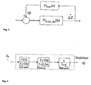
Fig. 3 shows an example of the transfer function between the blade angle and the tower velocity as well as the transfer function for a stabiliser that damps vibrations with the eigenfrequency of the tower vibrations. - If we take a closer look at the system shown in
Fig. 3 and call the signal that comes in from the left (variation in blade angle) β 0, we can set up the expression for the tower velocities ΔŻ as
- For the tower vibrations we then get:

- Here, Hls (s) is the transfer function for the closed loop, including the stabiliser, from β 0 to ΔŻ.
- Additional damping that damps the tower vibrations at a given frequency ωeig can be designed by making:

- It should be noted that any stabiliser designed according to the criteria in (2.3) that will reduce the tower vibrations will not necessarily supply the system with enough damping to make it stable. Therefore, in addition, it is necessary to demand that the system is stable when selecting the controller parameters for the turbine in question.
- An example was based on the tower vibrations' eigenfrequency, ωeig , being approximately equal to 0.5 radians/second (feig ≈0.0795 Hz), i.e. on a vibration of the tower having a period of approximately 12.57 s. The stabiliser in accordance with the present invention, which was created to damp the tower vibrations that vibrate with the eigenfrequency, then had a transfer function as shown in
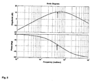
Fig. 4 . - A Bode plot of this transfer function is shown in
Fig. 5 . The Figure shows the frequency response of the designed stabiliser. The arrows define amplitude and phase in connection with the eigenfrequency of the tower dynamics. - In the elementary diagram shown in
Fig. 6 , the stabiliser solution is included in the control solution in accordance with the present invention, and the Figure shows how the output signal from the stabiliser is designed to modulate the turbine's blade angle, β. The principle of the solution in accordance with the present invention is thus to damp the tower's eigenvibrations by controlling the blade angle of the turbine blades so that the eigenvibrations are counteracted. The stabiliser is designed so that it only has to affect the blade angle in the frequency range near the tower vibrations' eigenfrequency, ωeig.. A high-pass filter ensures that no (zero) amplification is provided at low frequencies, and a low-pass filter ensures that no (zero) amplification is provided at high frequencies. Moreover, a phase-compensating filter must be tuned so that the phase distortion in the stabiliser is such that additional damping, Δβ (+ or -), damps the vibrations inΔZ that are caused by the tower vibrations' eigenfrequency, weig.. In other words, this means that the blade angle is affected by an amplitude and phase in relation to the tower's velocityΔZ in such a way that it damps the vibrations in the tower that have frequency ωeig. - Using the stabiliser leads to the turbine experiencing a relative wind velocity with greatly reduced influence from the tower's eigenvibrations in relation to a situation in which the stabiliser is not used. In addition, the tower will physically vibrate much less when a stabiliser is used.
- On the basis of the control solution as described above, simulation tests were carried out for two wind series with a mean wind velocity of 17.43 m/sec. and 20.04 m/sec. These velocities were selected because the need for damping is greatest at such high wind velocities, i.e. when the turbines are operated in constant power mode.
-
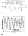
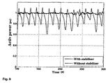
Figs. 7 and8 show a selection of results from the simulation of wind series at 17.43 m/sec. with and without stabilisers for damping tower vibrations. -
Fig. 7 shows that there are considerable tower vibrations when the turbine runs in constant power mode and the stabiliser is not used. This also results in large fluctuations in power supplied to the grid (seeFig. 8 ). The high amplitudes in the tower vibrations can be explained as follows: - In the constant RPM range, the thrust is reduced when the wind velocity increases. If the tower assumes a rearward velocity, the relative wind velocity that the tower experiences will be reduced. The blade angle (pitch) will be adjusted (increased) to maintain the moment and thus constant power. Thus the thrust will also increase despite the reduced relative wind velocity. Accordingly, when the tower moves at a velocity against the wind direction, the relative wind velocity will increase. The blade angle (pitch) will be adjusted (reduced) to reduce the moment. This will also reduce the thrust. This method of regulating the turbine will thus produce a variation in the thrust that acts in the same direction as the tower movement. I.e. negative damping. This will result in an amplification of the tower movement, in particular near the tower's resonance period in which the movement is controlled by damping. These are the tower vibrations that the stabiliser described above was designed to damp. In the example in question, the vibrations are so large that, even if the turbine runs in constant power mode, it is not able to supply constant power,
Fig. 8 . - If the stabiliser in accordance with the present invention is used,
Fig. 7 shows that the tower vibrations are damped well, andFig. 8 shows that the power variation is also considerably reduced. The stabiliser thus produces the desired effect. In parts of the simulation, the amplitude of the tower vibrations is reduced from over 10 m without a stabiliser to under 1 m with a stabiliser. -
Fig. 9 andFig. 10 show the results for the case with 20.04 m/sec. wind velocity. It can be seen that the turbine supplies approximately constant power without a stabiliser,Fig. 9 , but that the tower vibrations gradually build up to large fluctuations,Fig. 10 . If a stabiliser is used, the power remains approximately constant, while a considerable reduction in the tower movement is achieved. -
Fig. 11 shows a general diagram of a wind turbine including the stabiliser in accordance with the present invention. Legend for the figures: - ut - Resulting wind velocity on the turbine
- β - Blade angle
- Tturb - Mechanical moment on the turbine side of the shaft
- Tg - Mechanical moment on the generator side of the shaft
- ωt - RPM on the turbine side of the shaft
- ωg - RPM on the generator side of the shaft
- ng - Yaw conversion (in the present document this is equal to 1)
- uf - Permanent magnet generator's internal voltage
- f1 - Frequency of the permanent magnet generator's terminal voltage
- Ps - Active power supplied from the permanent magnet generator
- Us - Permanent magnet generator's terminal voltage
- Ud - Voltage in the DC intermediate circuit
- fn - Frequency of the mains voltage
- Qnet - Reactive power supplied from the wind turbine to the grid
- In short, the stabiliser acts by receiving the signal associated with the change in tower velocity,
ΔZ , from a sensor (not shown) in the form of an accelerometer or similar. The signal is "processed" by the stabiliser, which emits a new signal to a controller for the rotor blades to change the pitch angle, Δβ, of the blades to achieve the desired damping of the vibrations in the tower as described above. - The invention, as it is defined in the claims, is not limited to the examples described above. Therefore, the pitch of the turbine blades of the wind turbine may be controlled jointly, i.e. the same pitch angle, β, for all blades, or individually with a different pitch angle for each blade.
Claims (12)
- A method for damping tower vibrations in a floating wind turbine installation, the installation comprising a floating cell, a tower arranged over the floating cell, a generator mounted on the tower that is rotatable in relation to the wind direction and fitted with a wind turbine comprising turbine blades, and an anchor line arrangement that is connectable to anchors or foundations on a sea bed;
wherein the method comprises:controlling the generator in response to changes in the relative wind velocity against the turbine, by controlling the blade angle of the turbine blades by means of a controller in the constant power or RPM range of the wind turbine; anddamping the tower's eigenvibrations (ωeig) by, in addition to controlling the controller in the constant power or RPM range of the wind turbine, an increment (Δβ) being added to the blade angle of the turbine blades on the basis of the tower velocities (ΔŻ), so that the eigenvibrations of the tower are counteracted;wherein the vibrations in the horizontal displacement of the top of the tower (ΔZ) that have frequency ωeig are damped by means of a stabiliser with a transfer function (Hstab(s)) between the tower velocities (ΔŻ) and the blade angle increment (Δβ) andwherein the stabiliser is provided with a low pass filter that is arranged such that the stabiliser does not affect the blade angle at frequencies in a range above the tower vibrations' eigenfrequency (ωeig). - A method as claimed in claim 1, wherein the transfer function (Hstab(s)) between the tower velocities (ΔŻ) and the blade angle increment (Δβ) is such that the loop transfer function Hβ-ΔZ_dot (jωeig )·Hstab (jωeig )=-b,
which means that:
where "b" is a variable that depends on the moment and thrust characteristics of the blades. - A method as claimed in claim 1 or 2, wherein the transfer function (Hstab(s)) between the tower velocities (AŻ) and the blade angle increment (Δβ) is such that the loop transfer function Hβ-ΔZ_dot (jωeig )·Hstab (jωeig )=-1, which means that:

- A method as claimed in any of claims 1 to 3, wherein the stabiliser is provided with a high-pass filter that ensures that no amplification is provided at low frequencies.
- A method as claimed in any of claims 1 to 4, wherein the stabiliser is provided with a phase-compensating filter that is tuned so that the phase distortion in the stabiliser is such that the blade angle increment (Δβ) damps the vibrations in the tower velocites (ΔŻ) that are caused by the tower vibrations' eigenfrequency (ωeig).
- A method as claimed in any of claims 1 to 5, wherein the pitch (β) of each of the turbine blades is controlled individually.
- A blade angle controller for controlling the blade angle of turbine blades on a floating wind turbine installation, the installation comprising a floating cell, a tower arranged over the floating cell, a generator mounted on the tower that is rotatable in relation to the wind direction and fitted with a wind turbine comprising turbine blades, and an anchor line arrangement that is connectable to anchors or foundations on a sea bed;
wherein the blade angle controller is adapted to control the generator in response to changes in the relative wind velocity against the turbine, by controlling the blade angle of the turbine blades in the constant power or RPM range of the wind turbine; and
to damp the tower's eigenvibrations (ωeig) by, in addition to controlling the blade angle of the turbine blades in the constant power or RPM range of the wind turbine, an increment (Δβ) being added to the blade angle of the turbine blades on the basis of the tower velocities (ΔŻ) so that the eigenvibrations of the tower are counteracted;
wherein the vibrations in the horizontal displacement of the top of the tower (ΔZ) that have frequency ωeig are damped by means of a stabiliser with a transfer function (Hstab(s)) between the tower velocities (ΔŻ) and the blade angle increment (Δβ) and
wherein the stabiliser is provided with a low pass filter that is arranged such that the stabiliser does not affect the blade angle at frequencies in a range above the tower vibrations' eigenfrequency (ωeig). - A blade angle controller as claimed in claim 7, wherein the transfer function (Hstab(s)) between the tower velocities (ΔŻ) and the blade angle increment (Δβ) is such that the loop transfer function Hβ-ΔZ_dot (jωeig )·Hstab (jωeig )=-b,
which means that:
where "b" is a variable that depends on the moment and thrust characteristics of the blades. - A blade angle controller as claimed in claim 7 or 8, wherein the transfer function (Hstab(s)) between the tower velocities (ΔŻ) and the blade angle increment (Δβ) is such that the loop transfer function Hβ-ΔZ_dot (jωeig )·Hstab (jωeig )=-1,
which means that:
- A blade angle controller as claimed in any of claims 7 to 9, wherein the stabiliser is provided with a high-pass filter that ensures that no amplification is provided at low frequencies.
- A blade angle controller as claimed in any of claims 7 to 10, wherein the stabiliser is provided with a phase-compensating filter that is tuned so that the phase distortion in the stabiliser is such that the blade angle increment (Δβ) damps the vibrations in tower velocities (ΔŻ) that are caused by the tower vibrations' eigenfrequency (ωeig).
- A blade angle controller as claimed in any of claims 7 to 11, wherein the pitch (β) of each of the turbine blades is controlled individually.
Priority Applications (1)
| Application Number | Priority Date | Filing Date | Title |
|---|---|---|---|
| PL06812802T PL1952017T3 (en) | 2005-11-01 | 2006-10-30 | A method for damping tower vibrations in a wind turbine installation |
Applications Claiming Priority (2)
| Application Number | Priority Date | Filing Date | Title |
|---|---|---|---|
| NO20055118A NO325856B1 (en) | 2005-11-01 | 2005-11-01 | Method for damping unstable free rigid body oscillations in a floating wind turbine installation |
| PCT/NO2006/000385 WO2007053031A1 (en) | 2005-11-01 | 2006-10-30 | A method for damping tower vibrations in a wind turbine installation |
Publications (3)
| Publication Number | Publication Date |
|---|---|
| EP1952017A1 EP1952017A1 (en) | 2008-08-06 |
| EP1952017A4 EP1952017A4 (en) | 2012-05-02 |
| EP1952017B1 true EP1952017B1 (en) | 2015-12-09 |
Family
ID=35432892
Family Applications (1)
| Application Number | Title | Priority Date | Filing Date |
|---|---|---|---|
| EP06812802.4A Active EP1952017B1 (en) | 2005-11-01 | 2006-10-30 | A method for damping tower vibrations in a wind turbine installation |
Country Status (10)
| Country | Link |
|---|---|
| US (1) | US8186949B2 (en) |
| EP (1) | EP1952017B1 (en) |
| JP (1) | JP2009513881A (en) |
| CN (2) | CN102943743B (en) |
| BR (1) | BRPI0618151B1 (en) |
| CA (1) | CA2627148C (en) |
| ES (1) | ES2560504T3 (en) |
| NO (1) | NO325856B1 (en) |
| PL (1) | PL1952017T3 (en) |
| WO (1) | WO2007053031A1 (en) |
Cited By (1)
| Publication number | Priority date | Publication date | Assignee | Title |
|---|---|---|---|---|
| US12534166B2 (en) | 2021-03-22 | 2026-01-27 | Siemens Gamesa Renewable Energy A/S | Method and device of controlling an operation of a floating wind turbine |
Families Citing this family (55)
| Publication number | Priority date | Publication date | Assignee | Title |
|---|---|---|---|---|
| DE102004013131A1 (en) * | 2004-03-17 | 2005-10-06 | Siemens Ag | Wind turbine |
| WO2007104306A1 (en) * | 2006-03-16 | 2007-09-20 | Vestas Wind Systems A/S | A method and control system for reducing the fatigue loads in the components of a wind turbine subjected to asymmetrical loading of the rotor plane |
| CN101484699A (en) * | 2006-06-30 | 2009-07-15 | 维斯塔斯风力系统有限公司 | Wind turbine tower and a control system and method for altering the eigenfrequency of a wind turbine tower |
| NO335851B1 (en) * | 2006-08-22 | 2015-03-09 | Hywind As | Procedure for wind turbine installation for damping tower oscillations |
| ES2361575T3 (en) * | 2006-12-28 | 2011-06-20 | Clipper Windpower, Inc. | AMORTIGUATION OF THE RESONANT MOVEMENT OF THE TOWER AND THE SYMMETRIC MOVEMENT OF THE SHOES OF A WIND TURBINE USING ESTIMATION PROCEDURES. |
| ES2553168T5 (en) * | 2007-03-30 | 2018-12-10 | Vestas Wind Systems A/S | Wind turbine with step control |
| EP2063110B2 (en) | 2007-11-26 | 2019-06-12 | Siemens Aktiengesellschaft | Method of damping tower vibrations of a wind turbine and inclination control system |
| DE102007063082B4 (en) * | 2007-12-21 | 2010-12-09 | Repower Systems Ag | Method for operating a wind energy plant |
| US8277185B2 (en) * | 2007-12-28 | 2012-10-02 | General Electric Company | Wind turbine, wind turbine controller and method for controlling a wind turbine |
| US8004100B2 (en) * | 2008-03-14 | 2011-08-23 | General Electric Company | Model based wind turbine drive train vibration damper |
| ES2528743T3 (en) | 2008-04-02 | 2015-02-12 | Siemens Aktiengesellschaft | Vibration damping method of a wind turbine tower and control system for wind turbines |
| EP2123906A1 (en) | 2008-05-21 | 2009-11-25 | Siemens Aktiengesellschaft | Method and apparatus for damping tower oscillation in a wind turbine |
| EP2146093B1 (en) * | 2008-07-16 | 2011-10-26 | Siemens Aktiengesellschaft | Method and arrangement for damping of tower-oscillations |
| GB2466649B (en) * | 2008-12-30 | 2014-01-29 | Hywind As | Blade pitch control in a wind turbine installation |
| EP2224129B1 (en) * | 2009-02-27 | 2016-09-21 | Acciona Windpower S.a. | Wind turbine control method to dampen vibrations |
| GB0907132D0 (en) | 2009-04-24 | 2009-06-03 | Statoilhydro Asa | Wave energy extraction |
| WO2010144567A1 (en) * | 2009-06-09 | 2010-12-16 | Houvener Robert C | Hydrokinetic energy transfer device and method |
| US8207625B1 (en) | 2009-09-28 | 2012-06-26 | Constantine Gus Cristo | Electrical power generating arrangement |
| CA2693802C (en) * | 2010-01-27 | 2013-05-21 | Mitsubishi Heavy Industries, Ltd. | Wind turbine generator and yaw rotation control method for wind turbine generator |
| US8022566B2 (en) * | 2010-06-23 | 2011-09-20 | General Electric Company | Methods and systems for operating a wind turbine |
| DE102010041508A1 (en) * | 2010-09-28 | 2012-03-29 | Repower Systems Se | Speed adaptation of a wind energy plant |
| DK2463517T3 (en) * | 2010-12-08 | 2014-07-21 | Siemens Ag | Method and control system for reducing vibrations of a wind power plant |
| US8215896B2 (en) * | 2010-12-20 | 2012-07-10 | General Electric Company | Apparatus and method for operation of an off-shore wind turbine |
| US8169098B2 (en) * | 2010-12-22 | 2012-05-01 | General Electric Company | Wind turbine and operating same |
| EP2479426B1 (en) * | 2011-01-24 | 2017-06-28 | Siemens Aktiengesellschaft | Method for determining a pitch angle offset signal and for controlling a rotor frequency of a wind turbine for speed avoidance control |
| WO2013065323A1 (en) * | 2011-11-04 | 2013-05-10 | 独立行政法人海上技術安全研究所 | Control device for floating-body-type marine wind power generation apparatus |
| US20120133134A1 (en) * | 2011-11-15 | 2012-05-31 | General Electric Company | Method and apparatus for damping vibrations in a wind energy system |
| ES2407955B1 (en) | 2011-12-12 | 2014-05-08 | Acciona Windpower, S.A. | AEROGENERATOR CONTROL PROCEDURE |
| US9644606B2 (en) * | 2012-06-29 | 2017-05-09 | General Electric Company | Systems and methods to reduce tower oscillations in a wind turbine |
| GB201223088D0 (en) * | 2012-12-20 | 2013-02-06 | Statoil Asa | Controlling motions of floating wind turbines |
| US10024303B2 (en) | 2012-12-27 | 2018-07-17 | Mhi Vestas Offshore Wind A/S | Method and device for controlling floating body wind turbine power generating apparatus, and floating body wind turbine power generating apparatus |
| CN103244349B (en) * | 2013-04-24 | 2015-04-01 | 北京金风科创风电设备有限公司 | Fan tower vibration suppression system and control system for improving fan cut-out wind speed |
| JP6388759B2 (en) * | 2013-05-29 | 2018-09-12 | エムエイチアイ ヴェスタス オフショア ウィンド エー/エス | Floating wind power generator |
| KR101822535B1 (en) * | 2013-05-30 | 2018-01-26 | 엠에이치아이 베스타스 오프쇼어 윈드 에이/에스 | Tilt damping of a floating wind turbine |
| CN103334876B (en) * | 2013-07-16 | 2015-04-01 | 北京金风科创风电设备有限公司 | Three-order frequency vibration suppression system and method of fan blade on impeller rotation plane |
| CN103541861B (en) * | 2013-10-30 | 2016-02-24 | 新疆金风科技股份有限公司 | Floating type tower frame for wind generating set negative damping suppresses system and method |
| US10145361B2 (en) | 2013-11-25 | 2018-12-04 | General Electric Company | Methods and systems to shut down a wind turbine |
| US10619623B2 (en) | 2013-12-09 | 2020-04-14 | Verstas Wind Systems A/S | Selective wind turbine damping using active damping system |
| ES2656684T3 (en) * | 2014-08-13 | 2018-02-28 | Vestas Wind Systems A/S | Improvements in relation to the determination of imbalances of the rotor in a wind turbine |
| DK179069B1 (en) * | 2015-09-04 | 2017-10-02 | Envision Energy Denmark Aps | A wind turbine and a method of operating a wind turbine with a rotational speed exclusion zone |
| JP6506664B2 (en) * | 2015-09-10 | 2019-04-24 | 株式会社日立製作所 | Wind power generation system or control method of wind power generation system |
| CN105604790B (en) * | 2015-12-29 | 2018-05-04 | 北京天诚同创电气有限公司 | Wind turbine generator and stable control device and method thereof |
| WO2019114908A1 (en) * | 2017-12-14 | 2019-06-20 | Vestas Wind Systems A/S | Tower damping in wind turbine power production |
| DE102018005134A1 (en) * | 2018-06-28 | 2020-01-02 | Senvion Gmbh | Method and control for operating a wind turbine |
| US11635062B2 (en) | 2018-11-07 | 2023-04-25 | General Electric Renovables Espana, S.L. | Wind turbine and method to determine modal characteristics of the wind turbine in a continuous manner |
| US11208986B2 (en) | 2019-06-27 | 2021-12-28 | Uptake Technologies, Inc. | Computer system and method for detecting irregular yaw activity at a wind turbine |
| US10975841B2 (en) * | 2019-08-02 | 2021-04-13 | Uptake Technologies, Inc. | Computer system and method for detecting rotor imbalance at a wind turbine |
| ES2812374B2 (en) * | 2019-09-16 | 2022-02-17 | Esteyco S A | CONTROL PROCEDURE OF A FLOATING TYPE OFFSHORE WIND TURBINE, AS WELL AS THE SYSTEM AND THE WIND TURBINE THAT INCORPORATES THIS PROCEDURE |
| CN111396249B (en) * | 2020-03-31 | 2022-08-30 | 新疆金风科技股份有限公司 | Method and device for reducing tower load under gust wind condition |
| NO347048B1 (en) * | 2020-06-19 | 2023-04-24 | Ocean Ventus AS | Floating support structure for offshore windmill |
| GB2602301B (en) * | 2020-12-22 | 2023-03-29 | Equinor Energy As | Floating wind turbine control below rated wind speed |
| CN114562427B (en) * | 2022-02-21 | 2024-06-18 | 中国科学院工程热物理研究所 | An offshore wind turbine |
| CN115387960B (en) * | 2022-05-24 | 2026-03-03 | 北京华能新锐控制技术有限公司 | Independent variable pitch control method for floating offshore wind turbine |
| CN116505598B (en) * | 2023-06-26 | 2023-09-15 | 湖南大学 | Dynamic regulation and control method and system for service quality of wind turbine group |
| US12286888B1 (en) * | 2023-12-22 | 2025-04-29 | Ge Infrastructure Technology Llc | Mitigation of rotating stall in turbine section using outer flow control vanes |
Family Cites Families (20)
| Publication number | Priority date | Publication date | Assignee | Title |
|---|---|---|---|---|
| JPS5817884A (en) | 1981-07-23 | 1983-02-02 | Ebara Infilco Co Ltd | Treatment of condensate |
| US4420692A (en) * | 1982-04-02 | 1983-12-13 | United Technologies Corporation | Motion responsive wind turbine tower damping |
| US4435647A (en) * | 1982-04-02 | 1984-03-06 | United Technologies Corporation | Predicted motion wind turbine tower damping |
| US4515525A (en) * | 1982-11-08 | 1985-05-07 | United Technologies Corporation | Minimization of the effects of yaw oscillations in wind turbines |
| DE19731918B4 (en) | 1997-07-25 | 2005-12-22 | Wobben, Aloys, Dipl.-Ing. | Wind turbine |
| DE69901876T2 (en) * | 1998-01-14 | 2003-02-20 | Dancontrol Engineering A/S, Hammel | VIBRATION DETECTING AND CONTROL SYSTEM FOR WIND TURBINE |
| DE10016912C1 (en) * | 2000-04-05 | 2001-12-13 | Aerodyn Eng Gmbh | Operation of offshore wind turbines dependent on the natural frequency of the tower |
| DE10106208C2 (en) * | 2001-02-10 | 2002-12-19 | Aloys Wobben | Wind turbine |
| DE10113038C2 (en) * | 2001-03-17 | 2003-04-10 | Aloys Wobben | Tower vibration monitoring |
| WO2003004869A1 (en) | 2001-07-06 | 2003-01-16 | Vestas Wind Systems A/S | Offshore wind turbine with floating foundation |
| JP2003113769A (en) | 2001-10-03 | 2003-04-18 | Mitsubishi Heavy Ind Ltd | Blade pitch angle control device and wind power generation device |
| US6888262B2 (en) * | 2003-02-03 | 2005-05-03 | General Electric Company | Method and apparatus for wind turbine rotor load control |
| NO20033807D0 (en) | 2003-08-27 | 2003-08-27 | Norsk Hydro As | Wind turbine for offshore use |
| WO2005083266A1 (en) * | 2004-02-27 | 2005-09-09 | Mitsubishi Heavy Industries, Ltd. | Wind turbine generator, active vibration damping method for the same, and wind turbine tower |
| NO20041208L (en) * | 2004-03-22 | 2005-09-23 | Sway As | Procedure for reducing axial power variations for rotor and directional control for wind power with active pitch control |
| US7317260B2 (en) * | 2004-05-11 | 2008-01-08 | Clipper Windpower Technology, Inc. | Wind flow estimation and tracking using tower dynamics |
| CN101429932A (en) | 2004-11-29 | 2009-05-13 | 蒂埃里·那瓦罗 | Positive displacement pump with reciprocating rotary piston |
| NO20052704L (en) * | 2005-06-06 | 2006-12-07 | Norsk Hydro As | Liquid wind turbine installation. |
| WO2007010322A1 (en) * | 2005-07-18 | 2007-01-25 | Clipper Windpower Technology, Inc. | Wind flow estimation and tracking using tower dynamics |
| ES2361575T3 (en) * | 2006-12-28 | 2011-06-20 | Clipper Windpower, Inc. | AMORTIGUATION OF THE RESONANT MOVEMENT OF THE TOWER AND THE SYMMETRIC MOVEMENT OF THE SHOES OF A WIND TURBINE USING ESTIMATION PROCEDURES. |
-
2005
- 2005-11-01 NO NO20055118A patent/NO325856B1/en unknown
-
2006
- 2006-10-30 BR BRPI0618151A patent/BRPI0618151B1/en active IP Right Grant
- 2006-10-30 JP JP2008538838A patent/JP2009513881A/en active Pending
- 2006-10-30 EP EP06812802.4A patent/EP1952017B1/en active Active
- 2006-10-30 PL PL06812802T patent/PL1952017T3/en unknown
- 2006-10-30 ES ES06812802.4T patent/ES2560504T3/en active Active
- 2006-10-30 CN CN201210333685.2A patent/CN102943743B/en active Active
- 2006-10-30 WO PCT/NO2006/000385 patent/WO2007053031A1/en not_active Ceased
- 2006-10-30 CN CN200680040818XA patent/CN101300422B/en active Active
- 2006-10-30 US US12/091,957 patent/US8186949B2/en active Active
- 2006-10-30 CA CA2627148A patent/CA2627148C/en active Active
Cited By (1)
| Publication number | Priority date | Publication date | Assignee | Title |
|---|---|---|---|---|
| US12534166B2 (en) | 2021-03-22 | 2026-01-27 | Siemens Gamesa Renewable Energy A/S | Method and device of controlling an operation of a floating wind turbine |
Also Published As
| Publication number | Publication date |
|---|---|
| WO2007053031A1 (en) | 2007-05-10 |
| CN102943743A (en) | 2013-02-27 |
| EP1952017A1 (en) | 2008-08-06 |
| NO325856B1 (en) | 2008-08-04 |
| CA2627148A1 (en) | 2007-05-10 |
| EP1952017A4 (en) | 2012-05-02 |
| NO20055118D0 (en) | 2005-11-01 |
| US20080260514A1 (en) | 2008-10-23 |
| NO20055118L (en) | 2007-05-02 |
| BRPI0618151A2 (en) | 2012-02-28 |
| BRPI0618151B1 (en) | 2019-01-02 |
| CA2627148C (en) | 2012-08-07 |
| CN101300422B (en) | 2012-11-07 |
| JP2009513881A (en) | 2009-04-02 |
| ES2560504T3 (en) | 2016-02-19 |
| PL1952017T3 (en) | 2016-04-29 |
| CN102943743B (en) | 2014-10-15 |
| HK1182160A1 (en) | 2013-11-22 |
| US8186949B2 (en) | 2012-05-29 |
| BRPI0618151A8 (en) | 2018-04-03 |
| CN101300422A (en) | 2008-11-05 |
Similar Documents
| Publication | Publication Date | Title |
|---|---|---|
| US8186949B2 (en) | Method for damping tower vibrations in a wind turbine installation | |
| EP2054620B1 (en) | Method for the damping of tower oscillations in wind power installations | |
| EP2935876B1 (en) | Controlling motions of floating wind turbines | |
| KR101660553B1 (en) | Blade pitch control in a wind turbine installation | |
| US9702344B2 (en) | Control method for a floating wind turbine | |
| WO2024223239A1 (en) | Active damping for an offshore wind turbine during idling | |
| US12331723B2 (en) | Floating wind turbine control below rated wind speed | |
| HK1182160B (en) | A method for damping tower vibrations in a wind turbine installation | |
| HK1210249B (en) | Controlling motions of floating wind turbines |
Legal Events
| Date | Code | Title | Description |
|---|---|---|---|
| PUAI | Public reference made under article 153(3) epc to a published international application that has entered the european phase |
Free format text: ORIGINAL CODE: 0009012 |
|
| 17P | Request for examination filed |
Effective date: 20080530 |
|
| AK | Designated contracting states |
Kind code of ref document: A1 Designated state(s): AT BE BG CH CY CZ DE DK EE ES FI FR GB GR HU IE IS IT LI LT LU LV MC NL PL PT RO SE SI SK TR |
|
| RIN1 | Information on inventor provided before grant (corrected) |
Inventor name: UHLEN, KJETIL Inventor name: NIELSEN, FINN, GUNNAR Inventor name: TANDE, JOHN, OLAV, GIAEVER Inventor name: SKAARE, BJORN Inventor name: NORHEIM, IAN |
|
| RIN1 | Information on inventor provided before grant (corrected) |
Inventor name: UHLEN, KJETIL Inventor name: SKAARE, BJORN Inventor name: TANDE, JOHN, OLAV, GIAEVER Inventor name: NORHEIM, IAN Inventor name: NIELSEN, FINN, GUNNAR |
|
| RIN1 | Information on inventor provided before grant (corrected) |
Inventor name: UHLEN, KJETIL Inventor name: NIELSEN, FINN, GUNNAR Inventor name: NORHEIM, IAN Inventor name: SKAARE, BJORN Inventor name: TANDE, JOHN, OLAV, GIAEVER |
|
| RIN1 | Information on inventor provided before grant (corrected) |
Inventor name: UHLEN, KJETIL Inventor name: NORHEIM, IAN Inventor name: TANDE, JOHN, OLAV, GIAEVER Inventor name: SKAARE, BJORN Inventor name: NIELSEN, FINN, GUNNAR |
|
| A4 | Supplementary search report drawn up and despatched |
Effective date: 20120329 |
|
| RIC1 | Information provided on ipc code assigned before grant |
Ipc: F03D 11/00 20060101ALI20120323BHEP Ipc: F03D 7/04 20060101AFI20120323BHEP |
|
| DAX | Request for extension of the european patent (deleted) | ||
| RAP1 | Party data changed (applicant data changed or rights of an application transferred) |
Owner name: HYWIND AS |
|
| GRAP | Despatch of communication of intention to grant a patent |
Free format text: ORIGINAL CODE: EPIDOSNIGR1 |
|
| INTG | Intention to grant announced |
Effective date: 20150602 |
|
| RIN1 | Information on inventor provided before grant (corrected) |
Inventor name: NIELSEN, FINN, GUNNAR Inventor name: UHLEN, KJETIL Inventor name: NORHEIM, IAN Inventor name: TANDE, JOHN, OLAV, GIAEVER Inventor name: SKAARE, BJOERN |
|
| GRAS | Grant fee paid |
Free format text: ORIGINAL CODE: EPIDOSNIGR3 |
|
| GRAA | (expected) grant |
Free format text: ORIGINAL CODE: 0009210 |
|
| AK | Designated contracting states |
Kind code of ref document: B1 Designated state(s): AT BE BG CH CY CZ DE DK EE ES FI FR GB GR HU IE IS IT LI LT LU LV MC NL PL PT RO SE SI SK TR |
|
| REG | Reference to a national code |
Ref country code: GB Ref legal event code: FG4D |
|
| REG | Reference to a national code |
Ref country code: AT Ref legal event code: REF Ref document number: 764702 Country of ref document: AT Kind code of ref document: T Effective date: 20151215 Ref country code: CH Ref legal event code: EP |
|
| REG | Reference to a national code |
Ref country code: IE Ref legal event code: FG4D |
|
| REG | Reference to a national code |
Ref country code: DE Ref legal event code: R096 Ref document number: 602006047484 Country of ref document: DE |
|
| REG | Reference to a national code |
Ref country code: ES Ref legal event code: FG2A Ref document number: 2560504 Country of ref document: ES Kind code of ref document: T3 Effective date: 20160219 |
|
| REG | Reference to a national code |
Ref country code: SE Ref legal event code: TRGR |
|
| REG | Reference to a national code |
Ref country code: PT Ref legal event code: SC4A Free format text: AVAILABILITY OF NATIONAL TRANSLATION Effective date: 20160210 |
|
| REG | Reference to a national code |
Ref country code: LT Ref legal event code: MG4D |
|
| REG | Reference to a national code |
Ref country code: NL Ref legal event code: MP Effective date: 20151209 |
|
| PG25 | Lapsed in a contracting state [announced via postgrant information from national office to epo] |
Ref country code: LT Free format text: LAPSE BECAUSE OF FAILURE TO SUBMIT A TRANSLATION OF THE DESCRIPTION OR TO PAY THE FEE WITHIN THE PRESCRIBED TIME-LIMIT Effective date: 20151209 |
|
| REG | Reference to a national code |
Ref country code: AT Ref legal event code: MK05 Ref document number: 764702 Country of ref document: AT Kind code of ref document: T Effective date: 20151209 |
|
| PG25 | Lapsed in a contracting state [announced via postgrant information from national office to epo] |
Ref country code: NL Free format text: LAPSE BECAUSE OF FAILURE TO SUBMIT A TRANSLATION OF THE DESCRIPTION OR TO PAY THE FEE WITHIN THE PRESCRIBED TIME-LIMIT Effective date: 20151209 Ref country code: GR Free format text: LAPSE BECAUSE OF FAILURE TO SUBMIT A TRANSLATION OF THE DESCRIPTION OR TO PAY THE FEE WITHIN THE PRESCRIBED TIME-LIMIT Effective date: 20160310 Ref country code: LV Free format text: LAPSE BECAUSE OF FAILURE TO SUBMIT A TRANSLATION OF THE DESCRIPTION OR TO PAY THE FEE WITHIN THE PRESCRIBED TIME-LIMIT Effective date: 20151209 Ref country code: FI Free format text: LAPSE BECAUSE OF FAILURE TO SUBMIT A TRANSLATION OF THE DESCRIPTION OR TO PAY THE FEE WITHIN THE PRESCRIBED TIME-LIMIT Effective date: 20151209 |
|
| PG25 | Lapsed in a contracting state [announced via postgrant information from national office to epo] |
Ref country code: IS Free format text: LAPSE BECAUSE OF FAILURE TO SUBMIT A TRANSLATION OF THE DESCRIPTION OR TO PAY THE FEE WITHIN THE PRESCRIBED TIME-LIMIT Effective date: 20151209 |
|
| PG25 | Lapsed in a contracting state [announced via postgrant information from national office to epo] |
Ref country code: CZ Free format text: LAPSE BECAUSE OF FAILURE TO SUBMIT A TRANSLATION OF THE DESCRIPTION OR TO PAY THE FEE WITHIN THE PRESCRIBED TIME-LIMIT Effective date: 20151209 |
|
| PG25 | Lapsed in a contracting state [announced via postgrant information from national office to epo] |
Ref country code: AT Free format text: LAPSE BECAUSE OF FAILURE TO SUBMIT A TRANSLATION OF THE DESCRIPTION OR TO PAY THE FEE WITHIN THE PRESCRIBED TIME-LIMIT Effective date: 20151209 Ref country code: SK Free format text: LAPSE BECAUSE OF FAILURE TO SUBMIT A TRANSLATION OF THE DESCRIPTION OR TO PAY THE FEE WITHIN THE PRESCRIBED TIME-LIMIT Effective date: 20151209 Ref country code: IS Free format text: LAPSE BECAUSE OF FAILURE TO SUBMIT A TRANSLATION OF THE DESCRIPTION OR TO PAY THE FEE WITHIN THE PRESCRIBED TIME-LIMIT Effective date: 20160409 Ref country code: EE Free format text: LAPSE BECAUSE OF FAILURE TO SUBMIT A TRANSLATION OF THE DESCRIPTION OR TO PAY THE FEE WITHIN THE PRESCRIBED TIME-LIMIT Effective date: 20151209 Ref country code: RO Free format text: LAPSE BECAUSE OF FAILURE TO SUBMIT A TRANSLATION OF THE DESCRIPTION OR TO PAY THE FEE WITHIN THE PRESCRIBED TIME-LIMIT Effective date: 20151209 |
|
| REG | Reference to a national code |
Ref country code: DE Ref legal event code: R097 Ref document number: 602006047484 Country of ref document: DE |
|
| PLBE | No opposition filed within time limit |
Free format text: ORIGINAL CODE: 0009261 |
|
| STAA | Information on the status of an ep patent application or granted ep patent |
Free format text: STATUS: NO OPPOSITION FILED WITHIN TIME LIMIT |
|
| REG | Reference to a national code |
Ref country code: FR Ref legal event code: PLFP Year of fee payment: 11 |
|
| PG25 | Lapsed in a contracting state [announced via postgrant information from national office to epo] |
Ref country code: DK Free format text: LAPSE BECAUSE OF FAILURE TO SUBMIT A TRANSLATION OF THE DESCRIPTION OR TO PAY THE FEE WITHIN THE PRESCRIBED TIME-LIMIT Effective date: 20151209 |
|
| 26N | No opposition filed |
Effective date: 20160912 |
|
| PG25 | Lapsed in a contracting state [announced via postgrant information from national office to epo] |
Ref country code: SI Free format text: LAPSE BECAUSE OF FAILURE TO SUBMIT A TRANSLATION OF THE DESCRIPTION OR TO PAY THE FEE WITHIN THE PRESCRIBED TIME-LIMIT Effective date: 20151209 |
|
| PG25 | Lapsed in a contracting state [announced via postgrant information from national office to epo] |
Ref country code: BE Free format text: LAPSE BECAUSE OF FAILURE TO SUBMIT A TRANSLATION OF THE DESCRIPTION OR TO PAY THE FEE WITHIN THE PRESCRIBED TIME-LIMIT Effective date: 20151209 |
|
| REG | Reference to a national code |
Ref country code: CH Ref legal event code: PL |
|
| PG25 | Lapsed in a contracting state [announced via postgrant information from national office to epo] |
Ref country code: LI Free format text: LAPSE BECAUSE OF NON-PAYMENT OF DUE FEES Effective date: 20161031 Ref country code: CH Free format text: LAPSE BECAUSE OF NON-PAYMENT OF DUE FEES Effective date: 20161031 |
|
| PG25 | Lapsed in a contracting state [announced via postgrant information from national office to epo] |
Ref country code: LU Free format text: LAPSE BECAUSE OF NON-PAYMENT OF DUE FEES Effective date: 20161030 |
|
| REG | Reference to a national code |
Ref country code: FR Ref legal event code: PLFP Year of fee payment: 12 |
|
| PG25 | Lapsed in a contracting state [announced via postgrant information from national office to epo] |
Ref country code: CY Free format text: LAPSE BECAUSE OF FAILURE TO SUBMIT A TRANSLATION OF THE DESCRIPTION OR TO PAY THE FEE WITHIN THE PRESCRIBED TIME-LIMIT Effective date: 20151209 Ref country code: HU Free format text: LAPSE BECAUSE OF FAILURE TO SUBMIT A TRANSLATION OF THE DESCRIPTION OR TO PAY THE FEE WITHIN THE PRESCRIBED TIME-LIMIT; INVALID AB INITIO Effective date: 20061030 |
|
| PG25 | Lapsed in a contracting state [announced via postgrant information from national office to epo] |
Ref country code: TR Free format text: LAPSE BECAUSE OF FAILURE TO SUBMIT A TRANSLATION OF THE DESCRIPTION OR TO PAY THE FEE WITHIN THE PRESCRIBED TIME-LIMIT Effective date: 20151209 Ref country code: MC Free format text: LAPSE BECAUSE OF FAILURE TO SUBMIT A TRANSLATION OF THE DESCRIPTION OR TO PAY THE FEE WITHIN THE PRESCRIBED TIME-LIMIT Effective date: 20151209 |
|
| PG25 | Lapsed in a contracting state [announced via postgrant information from national office to epo] |
Ref country code: BG Free format text: LAPSE BECAUSE OF FAILURE TO SUBMIT A TRANSLATION OF THE DESCRIPTION OR TO PAY THE FEE WITHIN THE PRESCRIBED TIME-LIMIT Effective date: 20151209 |
|
| REG | Reference to a national code |
Ref country code: FR Ref legal event code: PLFP Year of fee payment: 13 |
|
| REG | Reference to a national code |
Ref country code: DE Ref legal event code: R082 Ref document number: 602006047484 Country of ref document: DE |
|
| P01 | Opt-out of the competence of the unified patent court (upc) registered |
Effective date: 20230524 |
|
| PGFP | Annual fee paid to national office [announced via postgrant information from national office to epo] |
Ref country code: PT Payment date: 20251020 Year of fee payment: 20 |
|
| PGFP | Annual fee paid to national office [announced via postgrant information from national office to epo] |
Ref country code: DE Payment date: 20251020 Year of fee payment: 20 |
|
| PGFP | Annual fee paid to national office [announced via postgrant information from national office to epo] |
Ref country code: GB Payment date: 20251017 Year of fee payment: 20 |
|
| PGFP | Annual fee paid to national office [announced via postgrant information from national office to epo] |
Ref country code: IT Payment date: 20251020 Year of fee payment: 20 |
|
| PGFP | Annual fee paid to national office [announced via postgrant information from national office to epo] |
Ref country code: FR Payment date: 20251017 Year of fee payment: 20 |
|
| PGFP | Annual fee paid to national office [announced via postgrant information from national office to epo] |
Ref country code: SE Payment date: 20251022 Year of fee payment: 20 |
|
| PGFP | Annual fee paid to national office [announced via postgrant information from national office to epo] |
Ref country code: IE Payment date: 20251023 Year of fee payment: 20 |
|
| PGFP | Annual fee paid to national office [announced via postgrant information from national office to epo] |
Ref country code: PL Payment date: 20251022 Year of fee payment: 20 |
|
| PGFP | Annual fee paid to national office [announced via postgrant information from national office to epo] |
Ref country code: ES Payment date: 20251114 Year of fee payment: 20 |