EP1950630A1 - A Fastening Mechanism for an Image Forming Apparatus - Google Patents
A Fastening Mechanism for an Image Forming Apparatus Download PDFInfo
- Publication number
- EP1950630A1 EP1950630A1 EP07121038A EP07121038A EP1950630A1 EP 1950630 A1 EP1950630 A1 EP 1950630A1 EP 07121038 A EP07121038 A EP 07121038A EP 07121038 A EP07121038 A EP 07121038A EP 1950630 A1 EP1950630 A1 EP 1950630A1
- Authority
- EP
- European Patent Office
- Prior art keywords
- coupling
- image forming
- unit
- disposed
- supporting cover
- Prior art date
- Legal status (The legal status is an assumption and is not a legal conclusion. Google has not performed a legal analysis and makes no representation as to the accuracy of the status listed.)
- Granted
Links
Images



Classifications
-
- G—PHYSICS
- G03—PHOTOGRAPHY; CINEMATOGRAPHY; ANALOGOUS TECHNIQUES USING WAVES OTHER THAN OPTICAL WAVES; ELECTROGRAPHY; HOLOGRAPHY
- G03G—ELECTROGRAPHY; ELECTROPHOTOGRAPHY; MAGNETOGRAPHY
- G03G15/00—Apparatus for electrographic processes using a charge pattern
- G03G15/14—Apparatus for electrographic processes using a charge pattern for transferring a pattern to a second base
-
- G—PHYSICS
- G03—PHOTOGRAPHY; CINEMATOGRAPHY; ANALOGOUS TECHNIQUES USING WAVES OTHER THAN OPTICAL WAVES; ELECTROGRAPHY; HOLOGRAPHY
- G03G—ELECTROGRAPHY; ELECTROPHOTOGRAPHY; MAGNETOGRAPHY
- G03G21/00—Arrangements not provided for by groups G03G13/00 - G03G19/00, e.g. cleaning, elimination of residual charge
- G03G21/16—Mechanical means for facilitating the maintenance of the apparatus, e.g. modular arrangements
- G03G21/1661—Mechanical means for facilitating the maintenance of the apparatus, e.g. modular arrangements means for handling parts of the apparatus in the apparatus
- G03G21/1671—Mechanical means for facilitating the maintenance of the apparatus, e.g. modular arrangements means for handling parts of the apparatus in the apparatus for the photosensitive element
-
- G—PHYSICS
- G03—PHOTOGRAPHY; CINEMATOGRAPHY; ANALOGOUS TECHNIQUES USING WAVES OTHER THAN OPTICAL WAVES; ELECTROGRAPHY; HOLOGRAPHY
- G03G—ELECTROGRAPHY; ELECTROPHOTOGRAPHY; MAGNETOGRAPHY
- G03G21/00—Arrangements not provided for by groups G03G13/00 - G03G19/00, e.g. cleaning, elimination of residual charge
- G03G21/16—Mechanical means for facilitating the maintenance of the apparatus, e.g. modular arrangements
- G03G21/1604—Arrangement or disposition of the entire apparatus
- G03G21/1623—Means to access the interior of the apparatus
-
- G—PHYSICS
- G03—PHOTOGRAPHY; CINEMATOGRAPHY; ANALOGOUS TECHNIQUES USING WAVES OTHER THAN OPTICAL WAVES; ELECTROGRAPHY; HOLOGRAPHY
- G03G—ELECTROGRAPHY; ELECTROPHOTOGRAPHY; MAGNETOGRAPHY
- G03G21/00—Arrangements not provided for by groups G03G13/00 - G03G19/00, e.g. cleaning, elimination of residual charge
- G03G21/16—Mechanical means for facilitating the maintenance of the apparatus, e.g. modular arrangements
- G03G21/1642—Mechanical means for facilitating the maintenance of the apparatus, e.g. modular arrangements for connecting the different parts of the apparatus
- G03G21/1647—Mechanical connection means
-
- G—PHYSICS
- G03—PHOTOGRAPHY; CINEMATOGRAPHY; ANALOGOUS TECHNIQUES USING WAVES OTHER THAN OPTICAL WAVES; ELECTROGRAPHY; HOLOGRAPHY
- G03G—ELECTROGRAPHY; ELECTROPHOTOGRAPHY; MAGNETOGRAPHY
- G03G21/00—Arrangements not provided for by groups G03G13/00 - G03G19/00, e.g. cleaning, elimination of residual charge
- G03G21/16—Mechanical means for facilitating the maintenance of the apparatus, e.g. modular arrangements
- G03G21/1661—Mechanical means for facilitating the maintenance of the apparatus, e.g. modular arrangements means for handling parts of the apparatus in the apparatus
- G03G21/168—Mechanical means for facilitating the maintenance of the apparatus, e.g. modular arrangements means for handling parts of the apparatus in the apparatus for the transfer unit
-
- G—PHYSICS
- G03—PHOTOGRAPHY; CINEMATOGRAPHY; ANALOGOUS TECHNIQUES USING WAVES OTHER THAN OPTICAL WAVES; ELECTROGRAPHY; HOLOGRAPHY
- G03G—ELECTROGRAPHY; ELECTROPHOTOGRAPHY; MAGNETOGRAPHY
- G03G2215/00—Apparatus for electrophotographic processes
- G03G2215/16—Transferring device, details
- G03G2215/1604—Main transfer electrode
- G03G2215/1623—Transfer belt
-
- G—PHYSICS
- G03—PHOTOGRAPHY; CINEMATOGRAPHY; ANALOGOUS TECHNIQUES USING WAVES OTHER THAN OPTICAL WAVES; ELECTROGRAPHY; HOLOGRAPHY
- G03G—ELECTROGRAPHY; ELECTROPHOTOGRAPHY; MAGNETOGRAPHY
- G03G2221/00—Processes not provided for by group G03G2215/00, e.g. cleaning or residual charge elimination
- G03G2221/16—Mechanical means for facilitating the maintenance of the apparatus, e.g. modular arrangements and complete machine concepts
- G03G2221/1642—Mechanical means for facilitating the maintenance of the apparatus, e.g. modular arrangements and complete machine concepts for the transfer unit
-
- G—PHYSICS
- G03—PHOTOGRAPHY; CINEMATOGRAPHY; ANALOGOUS TECHNIQUES USING WAVES OTHER THAN OPTICAL WAVES; ELECTROGRAPHY; HOLOGRAPHY
- G03G—ELECTROGRAPHY; ELECTROPHOTOGRAPHY; MAGNETOGRAPHY
- G03G2221/00—Processes not provided for by group G03G2215/00, e.g. cleaning or residual charge elimination
- G03G2221/16—Mechanical means for facilitating the maintenance of the apparatus, e.g. modular arrangements and complete machine concepts
- G03G2221/1651—Mechanical means for facilitating the maintenance of the apparatus, e.g. modular arrangements and complete machine concepts for connecting the different parts
- G03G2221/1654—Locks and means for positioning or alignment
Definitions
- the invention relates to a fastening mechanism for an image forming apparatus, particularly but not exclusively to an image forming apparatus including a removable image forming unit which transfers an image to an intermediate transfer belt of the image forming apparatus, and a fastening mechanism for a cover associated with the image forming unit.
- a conventional image forming apparatus 1 includes an engine frame 10, four toner cartridges 13, four image forming units 14, an intermediate transfer belt unit 20, and a supporting cover 30.
- the engine frame 10 supports the four toner cartridges 13, the four image forming units 14, the intermediate transfer belt unit 20, and the supporting cover 30.
- a printing medium feeding unit (not illustrated) that holds and feeds printing media
- a printing medium moving unit (not illustrated) to move a printing medium
- a transferring unit (not illustrated) to transfer color images formed on the intermediate transfer belt onto the printing medium
- a fusing unit (not illustrated) to fuse the transferred images onto the printing medium
- a discharging unit (not illustrated) to discharge the fused printing medium outside.
- Each of the four toner cartridges 13 holds a different color toner to develop electrostatic latent images formed on each of the image forming units 14.
- the four toner cartridges 13 hold black, yellow, magenta, and cyan toners, respectively.
- Each of the four image forming units 14 forms predetermined images corresponding to printing data and includes a photosensitive medium (not illustrated), a charging unit (not illustrated) to charge a surface of the photosensitive medium with a predetermined voltage, an exposure unit (not illustrated) to form electrostatic latent images on the surface of the photosensitive medium, and a developing unit (not illustrated) to develop the electrostatic latent images formed on the photosensitive medium with toner supplied from the toner cartridge 13.
- a fixing lever 40 is disposed at the engine frame 10 at a side of the transfer backup roller to transfer black toner images from the photosensitive medium to the intermediate transfer belt 21.
- the fixing lever 40 presses the transfer backup roller to cause the intermediate transfer belt 21 to come in contact with the photosensitive medium of the image forming unit 14a to form the black toner images. Then, the images on the photosensitive medium are transferred to the intermediate transfer belt 21.
- the transfer backup roller When turning the fixing lever 40 in a second direction, the transfer backup roller is released from the fixing lever 40 so that the intermediate transfer belt 21 comes apart from the photosensitive medium. In this state, when separating the image forming unit 14a, the photosensitive medium thereof does not rub against the intermediate transfer belt 21 so that no damages occur at the surfaces of the photosensitive medium and the intermediate transfer belt 21.
- the locking levers 32 and the fixing levers 40 are required to be operated separately.
- the two locking levers 32 are turned, and then, the supporting cover 30 is separated from the engine frame 10 so that the fixing levers 40 are exposed as illustrated in Figure 2 .
- the intermediate transfer belt 21 comes apart from the photosensitive medium. In this state, when the image forming unit 14a is separated, the photosensitive medium thereof does not rub against the intermediate transfer belt 21 so that no damage occurs.
- the present general inventive concept provides a locking apparatus and an image forming apparatus having the same, which is capable of fixing a plurality of parts by one action.
- the locking unit includes a locking handle rotatably disposed at the supporting cover, a cam gear coaxially disposed with the locking handle to rotate integrally with the locking handle, and a cover fixing member disposed at a side of the cam gear to project from a side surface of the supporting cover or to move inside the supporting cover according to an operation of the locking handle.
- the lever unit 170 may further include a fixing lever 175.
- the fixing lever 175 is disposed at a side of the lever shaft 171 and causes the intermediate transfer belt unit 120 to be fixed to a predetermined position of the engine frame 110.
- the fixing lever 175 fixes the intermediate transfer belt frame 123 to the engine frame 110 so that the intermediate transfer belt frame 123 does not become separated from the engine frame 110 in an axial direction of the lever shaft 171.
- the locking handle 151 When separating the supporting cover 130 from the engine frame 110, the locking handle 151 is rotated by approximately 90 degrees in a clockwise direction as illustrated in Figure 8A .
- the cam gear 153 formed integrally with the locking handle 151 also rotates by approximately 90 degrees.
- the cam gear 153 rotates by approximately 90 degrees, the cam part 154 of the cam gear 153, in contact with the back end of the cover fixing member 156, moves from the high point 154a to the low point 154b.
- Figure 4 illustrates the image forming apparatus 100 after the supporting cover 130 is separated.
- the cover fixing member 156 presses the elastic member 157 and moves so that the front end of the cover fixing member 156 projects from the side surface 130b of the supporting cover 130 as illustrated in Figure 8A .
- the front end of the cover fixing member 156 projects from the supporting cover 130, it is hooked to the hooking part 159 of the engine frame 110 so that the supporting cover 130 is fixed to the engine frame 110.
- a plurality of parts can be operated just by rotating a locking handle.
- the cover fixing member to fix the supporting cover, the press lever to cause the intermediate transfer belt to contact the photosensitive medium, and the fixing lever to fix the intermediate transfer belt unit to the engine frame can be operated at once.
Landscapes
- Physics & Mathematics (AREA)
- General Physics & Mathematics (AREA)
- Electrophotography Configuration And Component (AREA)
- Electrostatic Charge, Transfer And Separation In Electrography (AREA)
Abstract
Description
- The invention relates to a fastening mechanism for an image forming apparatus, particularly but not exclusively to an image forming apparatus including a removable image forming unit which transfers an image to an intermediate transfer belt of the image forming apparatus, and a fastening mechanism for a cover associated with the image forming unit.
- Generally, an image forming apparatus using an intermediate transfer belt has four image forming units so that it overlappingly transfers images formed on each of the four image forming units onto an intermediate transfer belt to form full color images.
-
Figures 1 and 2 are partial perspective views illustrating a conventional image forming apparatus. - Referring to
Figures 1 and 2 , a conventionalimage forming apparatus 1 includes anengine frame 10, fourtoner cartridges 13, fourimage forming units 14, an intermediatetransfer belt unit 20, and a supportingcover 30. - The
engine frame 10 supports the fourtoner cartridges 13, the fourimage forming units 14, the intermediatetransfer belt unit 20, and the supportingcover 30. Around theengine frame 10 are disposed a printing medium feeding unit (not illustrated) that holds and feeds printing media, a printing medium moving unit (not illustrated) to move a printing medium, a transferring unit (not illustrated) to transfer color images formed on the intermediate transfer belt onto the printing medium, a fusing unit (not illustrated) to fuse the transferred images onto the printing medium, and a discharging unit (not illustrated) to discharge the fused printing medium outside. - Each of the four
toner cartridges 13 holds a different color toner to develop electrostatic latent images formed on each of theimage forming units 14. In general, the fourtoner cartridges 13 hold black, yellow, magenta, and cyan toners, respectively. - Each of the four
image forming units 14 forms predetermined images corresponding to printing data and includes a photosensitive medium (not illustrated), a charging unit (not illustrated) to charge a surface of the photosensitive medium with a predetermined voltage, an exposure unit (not illustrated) to form electrostatic latent images on the surface of the photosensitive medium, and a developing unit (not illustrated) to develop the electrostatic latent images formed on the photosensitive medium with toner supplied from thetoner cartridge 13. - The intermediate
transfer belt unit 20 supports anintermediate transfer belt 21 to move endlessly in a closed loop, and includes theintermediate transfer belt 21 and an intermediatetransfer belt frame 23. Four transfer backup rollers (not illustrated) are disposed in positions corresponding to the photosensitive media of the fourimage forming units 14 inside theintermediate transfer belt 21. - A
fixing lever 40 is disposed at theengine frame 10 at a side of the transfer backup roller to transfer black toner images from the photosensitive medium to theintermediate transfer belt 21. When turning thefixing lever 40 in a first direction, thefixing lever 40 presses the transfer backup roller to cause theintermediate transfer belt 21 to come in contact with the photosensitive medium of theimage forming unit 14a to form the black toner images. Then, the images on the photosensitive medium are transferred to theintermediate transfer belt 21. - However, in this state, when separating or removing the
image forming unit 14a, the photosensitive medium thereof rubs against theintermediate transfer belt 21 so that damage such as scratches may occur at the surfaces of the photosensitive medium and theintermediate transfer belt 21. - When turning the
fixing lever 40 in a second direction, the transfer backup roller is released from thefixing lever 40 so that theintermediate transfer belt 21 comes apart from the photosensitive medium. In this state, when separating theimage forming unit 14a, the photosensitive medium thereof does not rub against theintermediate transfer belt 21 so that no damages occur at the surfaces of the photosensitive medium and theintermediate transfer belt 21. - The supporting
cover 30 rotatably supports ashaft 15 of each of the four photosensitive media so that the four photosensitive media of theimage forming units 14 can maintain predetermined intervals therebetween and rotate. Twolocking levers 32 are disposed at an outer surface of the supportingcover 30. Twolocking brackets 12 are disposed at positions of theengine frame 10 corresponding to the twolocking levers 32. Therefore, the supportingcover 30 is pushed against the side of theengine frame 10, and then, the twolocking levers 32 are turned to hook thelocking brackets 12 so that the supportingcover 30 is fixed to theengine frame 10. Also, thelocking levers 32 are turned in a reverse direction to escape from thelocking brackets 12 so that the supportingcover 30 can be separated from theengine frame 10. - However, the conventional
image forming apparatus 1 is configured so that the locking levers 32 to fix the supportingcover 30 to theengine frame 10 and thefixing levers 40 to cause theintermediate transfer belt 21 to contact the photosensitive medium operate separately. - As a result, in order to separate the
image forming unit 14 from theengine frame 10, the locking levers 32 and thefixing levers 40 are required to be operated separately. In other words, the twolocking levers 32 are turned, and then, the supportingcover 30 is separated from theengine frame 10 so that thefixing levers 40 are exposed as illustrated inFigure 2 . After that, when turning thefixing levers 40, theintermediate transfer belt 21 comes apart from the photosensitive medium. In this state, when theimage forming unit 14a is separated, the photosensitive medium thereof does not rub against theintermediate transfer belt 21 so that no damage occurs. - After mounting the
image forming unit 14a, the supportingcover 30 is mounted in the opposite of the above described procedure. In other words, after theimage forming unit 14a is mounted, thefixing levers 40 are turned to cause theintermediate transfer belt 21 to come in contact with the photosensitive medium. After that, the supportingcover 30 is pushed against theengine frame 10, and then, thelocking levers 32 are turned so that the supportingcover 30 is fixed to theengine frame 10. - In the conventional
image forming apparatus 1, when replacing or maintaining theimage forming unit 14a, it is required to turn thelocking levers 32 and thefixing lever 40 in order. Therefore, users experience inconvenience when replacing or maintaining theimage forming unit 14a. - The present general inventive concept provides a locking apparatus and an image forming apparatus having the same, which is capable of fixing a plurality of parts by one action.
- Additional aspects and utilities of the present general inventive concept will be set forth in part in the description which follows and, in part, will be obvious from the description, or may be learned by practice of the general inventive concept.
- The foregoing and/or other aspects and utilities can be achieved by providing a locking apparatus of an image forming apparatus, which includes a lever unit disposed at an intermediate transfer belt frame to cause an intermediate transfer belt to contact a photosensitive medium, a locking unit disposed at a supporting cover to cause the supporting cover to be fixed to and separated from an engine frame, and a coupling unit to cause the lever unit to operate in association with the locking unit.
- The lever unit includes a lever shaft rotatably supported by the intermediate transfer belt frame, and at least one press lever disposed at the lever shaft so as to be substantially vertical to the lever shaft.
- The lever unit may further include a fixing lever disposed at an end of the lever shaft to fix the intermediate transfer belt frame not to be separated from the engine frame in an axial direction of the lever shaft.
- The locking unit includes a locking handle rotatably disposed at the supporting cover, a cam gear coaxially disposed with the locking handle to rotate integrally with the locking handle, and a cover fixing member disposed at a side of the cam gear to project from a side surface of the supporting cover or to move inside the supporting cover according to an operation of the locking handle.
- Also, the locking unit may further include an elastic member to support the cover fixing member to move inside the supporting cover.
- The cam gear includes a gear part to cause the coupling unit to rotate, and a cam part to cause the cover fixing member to move.
- The coupling unit includes a first coupling disposed at the lever unit, a second coupling detachably coupled with the first coupling, and a coupling gear coaxially connected with the second coupling and rotatably disposed at the supporting cover. The second coupling can be provide with a plurality of jaws, and the first coupling can be provided with a plurality of holes into which the plurality of jaws is inserted. Also, the second coupling can be disposed at a shaft of the coupling gear so that it can move in an axial direction of the shaft of the coupling gear, and wherein the coupling unit further comprises a press member disposed between the second coupling and the coupling gear.
- The foregoing and/or other aspects and utilities of the present general inventive concept may also be achieved by providing an image forming apparatus that includes an engine frame disposed inside the image forming apparatus, an intermediate transfer belt unit disposed inside the engine frame to support an intermediate transfer belt to move endlessly in a closed loop, at least one image forming unit disposed below the intermediate transfer belt unit to comprise a photosensitive medium, a lever unit disposed at an intermediate transfer belt frame of the intermediate transfer belt unit to cause the intermediate transfer belt to contact the photosensitive medium, a locking unit disposed at a supporting cover to cause the supporting cover to be fixed to and separated from the engine frame, and a coupling unit to cause the lever unit to operate in association with the locking unit.
- The supporting cover can include at least one shaft hole formed at an inner surface thereof to support a shaft of the photosensitive medium of the at least one image forming unit.
- The image forming apparatus may further include at least one reference bushing disposed at the supporting cover, and at least one reference pin disposed at the engine frame corresponding to the at least one reference bushing, wherein when the supporting cover is mounted to the engine frame, the reference pin is inserted into the reference bushing.
- The foregoing and/or other aspects and utilities of the present general inventive concept may also be achieved by providing a locking apparatus of an image forming apparatus including a first member to extend and cause an intermediate transfer belt to contact a photosensitive medium, a second member to extend to and retract from a supporting cover to cause the supporting cover to be fixed to and separated from an engine frame, and a coupling unit to cause the first member to operate in association with the second member.
- The coupling unit can include a first coupling disposed at the first member, a second coupling detachably coupled with the first coupling, and a coupling gear coaxially connected with the second coupling and rotatably disposed at the supporting cover.
- The coupling unit may further include a cam gear to simultaneously rotate the coupling gear and to extend retract the second member.
- Embodiments of the invention will now be described, by way of example, with reference to the accompanying drawings, in which:
-
Figure 1 is a partial perspective view illustrating a conventional image forming apparatus with a supporting cover; -
Figure 2 is a partial perspective view illustrating the conventional image forming apparatus ofFigure 1 without the supporting cover; -
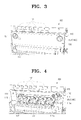
Figure 3 is a partial perspective view illustrating an image forming apparatus with a locking apparatus according to an embodiment of the present general inventive concept; -
Figure 4 is a partial perspective view illustrating the image forming apparatus ofFigure 3 without a supporting cover; -
Figure 5 is a rear perspective view illustrating a supporting cover of the image forming apparatus ofFigure 3 ; -
Figure 6 is a sectional view schematically illustrating a locking apparatus according to an embodiment of the present general inventive concept; -
Figure 7 is a perspective view illustrating a locking apparatus according to an embodiment of the present general inventive concept while separated from a coupling unit; -
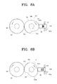
Figures 8A and 8B are a schematic view illustrating operation of a locking unit of a locking apparatus according to an embodiment of the present general inventive concept; and -
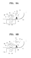
Figures 9A and 9B are a schematic view illustrating operation of a lever unit of a locking apparatus according to an embodiment of the present general inventive concept. - Throughout the drawings, like reference numerals will be understood to refer to like parts, components and structures.
- The matters defined in the description, such as a detailed construction and elements thereof, are provided to assist in a comprehensive understanding of the general inventive concept. Thus, it is apparent that the present general inventive concept may be carried out without those defined matters. Also, well-known functions or constructions are omitted to provide a clear and concise description of exemplary embodiments.
-
Figures 3 and 4 are a partial perspective view illustrating an image forming apparatus according to an embodiment.Figure 3 illustrates the image forming apparatus with a supporting cover, andFigure 4 illustrates the image forming apparatus without the supporting cover. - Referring to
Figures 3 and 4 , animage forming apparatus 100 according to an embodiment includes anengine frame 110, a plurality oftoner cartridges 112, a plurality ofimage forming units 114, an intermediatetransfer belt unit 120, a supportingcover 130, a usedtoner receptacle 117, and alocking unit 140. - The
engine frame 110 supports the plurality oftoner cartridges 112, the plurality ofimage forming units 114, the intermediatetransfer belt unit 120, and the supportingcover 130. Around theengine frame 110 are disposed a printing medium feeding unit (not illustrated) that holds and feeds printing media, a printing medium moving unit (not illustrated) to move a printing medium, a transferring unit (not illustrated) to transfer color images formed on the intermediate transfer belt onto the printing medium, a fusing unit (not illustrated) to fuse the transferred images onto the printing medium, and a discharging unit (not illustrated) to discharge the fused printing medium outside. Since the printing medium feeding unit, the printing medium moving unit, the transferring unit, and the discharging unit are substantially the same as those of a conventional image forming apparatus, detailed descriptions and drawings thereof will not be presented. - Each of the plurality of
toner cartridges 112 is disposed at an upper part of theengine frame 110 and holds a different color toner to develop electrostatic latent images formed on the photosensitive medium 116 (seeFigure 9A ) of theimage forming unit 114. Theimage forming apparatus 100 according to an embodiment has fourtoner cartridges 112, and thetoner cartridges 112 can hold black, yellow, magenta, and cyan toners, respectively. However other toners can be contained in thetoner cartridges 112. - The plurality of
image forming units 114 form predetermined images corresponding to printing data and are disposed below the intermediatetransfer belt unit 120. Each of theimage forming units 114 includes aphotosensitive medium 116, a charging unit (not illustrated) to charge a surface of thephotosensitive medium 116 with a predetermined voltage, an exposure unit (not illustrated) to form electrostatic latent images on the surface of thephotosensitive medium 116, and a developing unit (not illustrated) to develop the electrostatic latent images formed on thephotosensitive medium 116 with toner supplied from thetoner cartridge 112. Theimage forming apparatus 100 according to this embodiment uses fourimage forming units 114 corresponding to the fourtoner cartridges 112. Therefore, the fourimage forming units 114 form black, yellow, magenta, and cyan toner images, respectively, on thephotosensitive medium 116 thereof. - The intermediate
transfer belt unit 120 is disposed at theengine frame 110 below the plurality oftoner cartridges 112 and includes an intermediate transfer belt 121 (seeFIGS 9A and 9B ), an intermediate transfer belt frame 123 (seeFigure 6 ), a drive roller (not illustrated), and a driven roller (not illustrated). Theintermediate transfer belt 121 is disposed at the intermediatetransfer belt frame 123 and moves endlessly in a closed loop by the drive and driven rollers. When theintermediate transfer belt 121 moves endlessly in a closed loop, images formed on thephotosensitive medium 116 of each of the plurality ofimage forming units 114 are overlappingly transferred onto theintermediate transfer belt 121. A transfer backup roller 181 (seeFigure 9A ) is disposed in each position corresponding to a respective one of thephotosensitive media 116 of the plurality ofimage forming units 114 inside theintermediate transfer belt 121. Theimage forming apparatus 100 according to an embodiment is provided with fourtransfer backup rollers 181 corresponding to the fourimage forming units 114. The fourtransfer backup rollers 181 support theintermediate transfer belt 121 to contact thephotosensitive media 116 of theimage forming units 114 so that images formed on thephotosensitive media 116 are transferred onto theintermediate transfer belt 121. - The supporting
cover 130 is detachably disposed at a side of theengine frame 110, and rotatably supports ashaft 115 of each of the plurality ofphotosensitive media 116 so that thephotosensitive media 116 of the plurality ofimage forming units 114 can maintain intervals therebetween and rotate. Therefore, at aninner surface 130a of the supportingcover 130, as illustrated inFigure 5 , is formed a plurality of shaft holes 135 to rotatably support theshafts 115 of the plurality ofphotosensitive media 116. Theimage forming apparatus 100 according this embodiment is provided with fourshaft holes 135 formed at theinner surface 130a of the supportingcover 130 so as to supportshafts 115 of the fourphotosensitive media 116. - Also, at least one
reference bushing 131 is disposed at theinner surface 130a of the supportingcover 130 so that when the supportingcover 130 is fixed to theengine frame 110, it guides the supportingcover 130 to be fixed to a correct position. At theengine frame 110 is disposed at least one reference pin 111 (seeFigure 6 ) that is inserted into the at least onereference bushing 131 for the supportingcover 130 to be fixed to the correct position. A pair ofreference bushings 131 andreference pins 111 may be disposed at the supportingcover 130 and theengine frame 110 at predetermined intervals. - The used
toner receptacle 117 is disposed below theengine frame 110, and collects used toner discharged from the plurality ofimage forming units 114 and theintermediate transfer belt 121. - The
locking apparatus 140 causes the supportingcover 130 to be detachably fixed to theengine frame 110, theintermediate transfer belt 121 to come in contact with thephotosensitive medium 116 of theimage forming unit 114a to form black toner images, and the intermediatetransfer belt unit 120 to be fixed to theengine frame 110. Thelocking apparatus 140, referring toFigures 6 and7 , includes alever unit 170, alocking unit 150, and acoupling unit 160. - The
lever unit 170 is disposed at the intermediatetransfer belt frame 123, and causes theintermediate transfer belt 121 to be in contact with thephotosensitive medium 116. Thelever unit 170 is provided with alever shaft 171 to be rotatably supported by the intermediatetransfer belt frame 123, and at least onepress lever 173 that is disposed at thelever shaft 171 and substantially vertical to thelever shaft 171. In theimage forming apparatus 100 according to this embodiment, thelever unit 170 may have two press levers 173. - The
press lever 173 is formed so that when it moves to a press position as illustrated inFigure 9A , a front end of thepress lever 173 can press a first end of apress plate 180. A second end of thepress plate 180 is disposed byhinge 182 inside the intermediatetransfer belt frame 123. As a result, when thepress lever 173 presses the first end of thepress plate 180, thetransfer backup roller 181, which is rotatably disposed at thepress plate 180, moves downwardly. Then, thetransfer backup roller 181 presses theintermediate transfer belt 121 to come in contact with thephotosensitive medium 116 of theimage forming unit 114a. - As illustrated in
Figure 9B , when thelever shaft 171 rotates in a reverse direction to cause thepress lever 173 to leave the press position, the first end of thepress plate 180 moves upwardly due to areturn member 183, also referred to as a biasing member. Then, theintermediate transfer belt 121 is separated from thephotosensitive medium 116. - The
lever unit 170 may further include a fixinglever 175. The fixinglever 175 is disposed at a side of thelever shaft 171 and causes the intermediatetransfer belt unit 120 to be fixed to a predetermined position of theengine frame 110. In other words, the fixinglever 175 fixes the intermediatetransfer belt frame 123 to theengine frame 110 so that the intermediatetransfer belt frame 123 does not become separated from theengine frame 110 in an axial direction of thelever shaft 171. - When the
press lever 173 moves to the press position of pressing thepress plate 180, the fixinglever 175 inserts into a fixingrecess 177 formed at theengine frame 110. Therefore, when thepress lever 173 moves away from the press position, the fixinglever 175 also moves away from the fixingrecess 177. - The
locking unit 150 is disposed at the supportingcover 130 to cover a side surface of the intermediatetransfer belt unit 120, and formed to cause the supportingcover 130 to be fixed to or separated from theengine frame 110. Thelocking unit 150 includes alocking handle 151 to be rotatably disposed at an outer surface of the supportingcover 130, acam gear 153 coaxially coupled with the locking handle 151 to rotate integrally with thelocking handle 151, and acover fixing member 156 disposed at a side of thecam gear 153. Thecover fixing member 156 projects from aside surface 130b of the supportingcover 130 or moves inside the supportingcover 130 according to an operation of thelocking handle 151. In other words, the locking handle 151 can control the position of thecover fixing member 156. Also, inside the supportingcover 130 is disposed anelastic member 157 to press thecover fixing member 156 to move inside the supportingcover 130. - The
cam gear 153 is disposed to rotate integrally with the locking handle 151 via acam gear shaft 152, and is provided with agear part 155 and acam part 154 as illustrated inFigure 8A . Thegear part 155 of thecam gear 153 is formed to engage with acoupling gear 163 of thecoupling unit 160 within a rotation range of thelocking handle 151. Therefore, a rotation of the locking handle 151 causes thecoupling gear 163 to rotate. Thecam part 154 of thecam gear 153 is formed to cause thecover fixing member 156 to project from theside surface 130b of the supportingcover 130 or move inside the supportingcover 130 according to rotation of thelocking handle 151. - A cam profile of the
cam part 154 of thecam gear 153 is formed to have ahigh point 154a, where the outer edge of thecam gear 153 is at a relatively large radial distance from the cam gear shaft, at which thecam part 154 pushes thecover fixing member 156 to cause a front end of thecover fixing member 156 to project from theside surface 130b of the supportingcover 130, and alow point 154b, where the outer edge of thecam gear 153 is at a relatively small radial distance from the cam gear shaft, at which thecam part 154 causes the front end of thecover fixing member 156 to move inside the supportingcover 130. Therefore, when thelocking handle 151 rotates thecam gear 153 so that thecam part 154 of thecam gear 153, which is in contact with a back end of thecover fixing member 156, rotates from thelow point 154b to thehigh point 154a, the front end of thecover fixing member 156 projects from theside surface 130b of the supportingcover 130. Also, when thelocking handle 151 rotates thecam gear 153 in a reverse direction so that thecam part 154 of thecam gear 153, which is in contact with the back end of thecover fixing member 156, rotates from thehigh point 154a to thelow point 154b, thecover fixing member 156 moves back inside the supportingcover 130 due to a force of theelastic member 157. At this position, the front end of thecover fixing member 156 does not project from theside surface 130b of the supportingcover 130. - When the
locking handle 151 rotates in a first direction, thecam part 154 of thecam gear 153 causes thecover fixing member 156 to project from theside surface 130b of the supportingcover 130, and thegear part 155 of thecam gear 153 causes thelever shaft 171 to rotate so that thepress lever 173 presses the press plate 180 (Figures 9A and 9B ) and the fixinglever 175 moves into the fixing recess 177 (Figure 6 ). When thelocking handle 151 rotates in a second direction, thecover fixing member 156 is returned inside the supportingcover 130 by thecam part 154 of thecam gear 153 and theelastic member 157, and thepress lever 173 and fixinglever 175 are respectively moved away from thepress plate 180 and the fixingrecess 177 by thegear part 155 of thecam gear 153. - The
coupling unit 160 allows thelever unit 170 to operate in association with thelocking unit 150, and the supportingcover 130 to be separated from theengine frame 110. In other words, when the supportingcover 130 is separated from theengine frame 110, thecoupling unit 160 allows thelocking unit 150 of thelocking apparatus 140 to be separated from thelever unit 170 thereof. When the supportingcover 130 is fixed to theengine frame 110, thecoupling unit 160 allows thelocking unit 150 of thelocking apparatus 140 to be connected with thelever unit 170 thereof so that operation of thelocking handle 151 is transmitted to thelever unit 170 via thecoupling unit 160. - Referring to
Figures 6 and7 , thecoupling unit 160 includes afirst coupling 161 disposed at thelever unit 170, asecond coupling 162 detachably connected with thefirst coupling 161, and thecoupling gear 163 that is coaxially connected with thesecond coupling 162 and rotatably disposed at the supportingcover 130. Therefore, rotation of thecoupling gear 163 causes thesecond coupling 162 to rotate, and rotation of thesecond coupling 162 causes thefirst coupling 161 to rotate. The first andsecond couplings - In this embodiment, the
second coupling 162 is formed in a cylindrical shape with a plurality of jaws orteeth 162a at a front end thereof. Thefirst coupling 161 is formed in a hollow cylindrical shape capable of receiving thesecond coupling 162 and provided with a plurality ofholes 161a at a bottom surface thereof into which the plurality ofjaws 162a of thesecond coupling 162 is inserted. For example, if thesecond coupling 162 has twojaws 162a, thefirst coupling 161 has twoholes 161a. - Therefore, when the plurality of
jaws 162a of thesecond coupling 162 is inserted into the plurality ofholes 161a of thefirst coupling 161, a rotational force of thesecond coupling 162 is transmitted to thefirst coupling 161. - Furthermore, the
second coupling 162 may be formed in a hollow cylindrical shape so that it can move in an axial direction of ashaft 164 of thecoupling gear 163 but cannot rotate with respect to theshaft 164 of thecoupling gear 163. Apressure member 165, such as a compression spring, may be disposed between thesecond coupling 162 and thecoupling gear 163. Then, when the supportingcover 130 is fixed to theengine frame 110, thejaws 162a of thesecond coupling 162 press the bottom surface of thefirst coupling 161. As a result, when the supportingcover 130 is fixed to theengine frame 110 and thejaws 162a of thesecond coupling 162 is not inserted into theholes 161a of thefirst coupling 161, a user rotates the locking handle 151 so that thesecond coupling 162 rotates to cause thejaws 162a of thesecond coupling 162 to insert into theholes 161a of thefirst coupling 161. - Therefore, a rotational force of the
second coupling 162 is normally transmitted to thefirst coupling 161. - Referring back to
Figure 3 , theimage forming apparatus 100 is provided with two lockinghandles 151 and 151' disposed at the outer surface of the supportingcover 130. Aright locking handle 151 operates thelocking apparatus 140 according to an embodiment. However, a left locking handle 151' does not connect with thecoupling unit 160 of thelocking apparatus 140 according to an embodiment. Therefore, a rotation of the left locking handle 151' operates only thecover fixing member 156. - Hereinafter, operation of the
locking apparatus 140 of the image forming apparatus according to an embodiment will be explained in details with reference toFigures 6 and7 . - First, it will be explained how to separate the supporting
cover 130 from theengine frame 110, as illustrated inFigure 3 . - When separating the supporting
cover 130 from theengine frame 110, the lockinghandle 151 is rotated by approximately 90 degrees in a clockwise direction as illustrated inFigure 8A . When thelocking handle 151 rotates by approximately 90 degrees as illustrated inFigure 8B , thecam gear 153 formed integrally with the locking handle 151 also rotates by approximately 90 degrees. When thecam gear 153 rotates by approximately 90 degrees, thecam part 154 of thecam gear 153, in contact with the back end of thecover fixing member 156, moves from thehigh point 154a to thelow point 154b. Then, thecover fixing member 156 is moved inside the supportingcover 130 by theelastic member 157, disposed between thecover fixing member 156 and the supportingcover 130, so that the front end of thecover fixing member 156 escapes from a hookingpart 159. Therefore, a user can separate the supportingcover 130 from theengine frame 110. -
Figure 4 illustrates theimage forming apparatus 100 after the supportingcover 130 is separated. - In addition to the above operations, when the
cam gear 153 rotates by approximately 90 degrees in the clockwise direction, thecoupling gear 163, which is engaged with thegear part 154 of thecam gear 153, rotates in a counterclockwise direction. When thecoupling gear 163 rotates in the counterclockwise direction, thesecond coupling 162 coaxially disposed with thecoupling gear 163 rotates in the counterclockwise direction. When thesecond coupling 162 rotates, thefirst coupling 161, which is engaged with thesecond coupling 162, rotates. When thefirst coupling 161 rotates, thelever shaft 171 formed integrally with thefirst coupling 161 rotates in the counterclockwise direction. - When the
lever shaft 171 rotates in the counterclockwise direction, thepress lever 173 and fixinglever 175 also rotate by approximately 90 degrees in the counterclockwise direction. When thepress lever 173 rotates by approximately 90 degrees in the counterclockwise direction, the front end of thepress lever 173 moves away from thepress plate 180, as illustrated inFigure 9B . As a result, thepress plate 180 moves upwardly due to thereturn member 183 so that theintermediate transfer belt 121 is separated from thephotosensitive medium 116 of theimage forming unit 114a. When theintermediate transfer belt 121 is separated from thephotosensitive medium 116, thephotosensitive medium 116 does not rub against theintermediate transfer belt 121 during separation of theimage forming unit 114a from theengine frame 110 so that no scratch and/or damage occurs, for instance when moving thephotosensitive medium 116 relative to thetransfer belt 121. - When the fixing
lever 175 rotates by approximately 90 degrees in the counterclockwise direction due to movement of thelever shaft 171, the fixinglever 175 escapes from the fixingrecess 177 as illustrated inFigure 9B . Therefore, a user can separate the intermediatetransfer belt unit 120 from theengine frame 110. - When mounting the supporting
cover 130 to theengine frame 110, thereference bushing 131 formed at theinner surface 130a of the supportingcover 130 is brought in line with thereference pin 111 of theengine frame 110. Also, the fourshaft holes 135 formed at theinner surface 130a of the supportingcover 130 are brought in line with theshafts 115 of thephotosensitive media 116 of the fourimage forming units 114. Then, the supportingcover 130 is pushed to tightly contact theengine frame 110 so that thesecond coupling 162 of thelocking apparatus 140 is coupled with thefirst coupling 161 thereof. In this state, the locking handle 151 can be rotated by approximately 90 degrees in the counterclockwise direction so that thecover fixing member 156 projects out from theside surface 130b of the supportingcover 130, as illustrated inFigure 8A , thereby causing the supportingcover 130 to be fixed to theengine frame 110. Also, thepress lever 173 forces theintermediate transfer belt 121 to contact thephotosensitive medium 116, and the fixinglever 175 causes the intermediatetransfer belt unit 120 to be fixed to theengine frame 110. - Hereinafter, the process by which rotation of the locking handle 151 causes the
locking unit 150 and thelever unit 170 to operate will be explained in detail. When thelocking handle 151 rotates by approximately 90 degrees in the counterclockwise direction, thecam gear 153 rotated integrally with the locking handle 151 also rotates by approximately 90 degrees in the counterclockwise direction. When thecam gear 153 rotates by approximately 90 degrees, thecam part 154 of thecam gear 153 to contact the back end of thecover fixing member 156 moves from thelow point 154b to thehigh point 154a as illustrated inFigures 8B and 8A . As a result, thecover fixing member 156 presses theelastic member 157 and moves so that the front end of thecover fixing member 156 projects from theside surface 130b of the supportingcover 130 as illustrated inFigure 8A . When the front end of thecover fixing member 156 projects from the supportingcover 130, it is hooked to the hookingpart 159 of theengine frame 110 so that the supportingcover 130 is fixed to theengine frame 110. - When the
cam gear 153 rotates by approximately 90 degrees in the counterclockwise direction, thecoupling gear 163 engaged with thegear part 155 of thecam gear 153 rotates by approximately 90 degrees in the clockwise direction. When thecoupling gear 163 rotates by approximately 90 degrees in the clockwise direction, the first andsecond couplings lever shaft 171 to rotate by approximately 90 degrees in the clockwise direction. When thelever shaft 171 rotates by approximately 90 degrees in the clockwise direction, thepress lever 173 and the fixinglever 175 also rotate by approximately 90 degrees in the same direction. When thepress lever 173 rotates by approximately 90 degrees in the clockwise direction, the front end of thepress lever 173 presses thepress plate 180 as illustrated inFigure 9A . When thepress plate 180 is pressed, thetransfer backup roller 181 moves downwardly so that theintermediate transfer belt 121 comes in contact with thephotosensitive medium 116 of theimage forming unit 114a. Also, the fixinglever 175 rotates by approximately 90 degrees in the clockwise direction to insert into the fixingrecess 177 formed at theengine frame 110. As a result, the intermediatetransfer belt unit 120 is fixed to theengine frame 110. - As described above, with the
locking apparatus 140 of theimage forming apparatus 100 according to various embodiments, a plurality of parts, that is, thecover fixing member 156, thepress lever 173, and the fixinglever 175 can be operated just by rotating thelocking handle 151. In other words, when a user rotates the locking handle 151 in the first direction, the supportingcover 130 is fixed to theengine frame 110, theintermediate transfer belt 121 comes in contact with thephotosensitive medium 116, and the intermediatetransfer belt unit 120 is fixed to a predetermined position of theengine frame 110 so that theimage forming apparatus 100 becomes ready to perform a printing operation. - Furthermore, when the user rotates the locking handle 151 in the second direction, the supporting
cover 130 is separated from theengine frame 110, theintermediate transfer belt 121 comes apart from thephotosensitive medium 116, and fixing of the intermediatetransfer belt unit 120 is released so that theimage forming unit 114 can be separated from theengine frame 110 without damage. - As described above, with a locking apparatus of an image forming apparatus according to various embodiments and an image forming apparatus having the same, a plurality of parts can be operated just by rotating a locking handle. In other words, as a user rotates the locking handle, the cover fixing member to fix the supporting cover, the press lever to cause the intermediate transfer belt to contact the photosensitive medium, and the fixing lever to fix the intermediate transfer belt unit to the engine frame can be operated at once.
- Therefore, when replacing or just checking out the disposable image forming unit, a user rotates only the locking handle to separate the image forming unit from the engine frame. After replacing the image forming unit, the user closes the supporting cover and rotates only the locking handle so that the image forming apparatus becomes in a state ready to perform a print operation. As a result, according to the various embodiments, it is very convenient for a user to maintain the image forming apparatus.
- Although a few embodiments of the present general inventive concept have been shown and described, it will be appreciated by those skilled in the art that changes may be made in these embodiments without departing from the principles of the invention, the scope of which is defined in the appended claims.
Claims (18)
- A fastening mechanism for an image forming apparatus, the mechanism comprising:means for disengaging toner receiving means of the image forming apparatus from toner providing means associated with an image forming unit of the image forming apparatus;fastening means for fastening and unfastening a cover of the image forming apparatus to and from a portion of the image forming apparatus; andcoupling means arranged to cause the disengaging means to operate in association with the fastening means.
- A mechanism according to claim 1, wherein the image forming unit is removable from the image forming apparatus.
- A mechanism according to claim 1 or 2, wherein the disengaging means is further arranged to engage the toner receiving means with the toner providing means.
- A mechanism according to claim 1, 2 or 3, wherein the toner receiving means comprises an intermediate transfer belt disposed at a transfer belt frame, the toner providing means comprises a photosensitive medium and the disengaging means comprises a lever unit comprising:a lever shaft rotatably supported by the intermediate transfer belt frame; andat least one press lever disposed at the lever shaft to be substantially vertical to the lever shaft.
- A mechanism according to claim 4, wherein the lever unit further comprises:a fixing lever disposed at an end of the lever shaft to fix the intermediate transfer belt frame not to be separated from the engine frame in an axial direction of the lever shaft.
- A mechanism according to claim 4 or 5, wherein the cover comprises a supporting cover, the fastening means comprises a locking unit comprising:a locking handle rotatably disposed at the supporting cover;a cam gear coaxially disposed with the locking handle to rotate integrally with the locking handle; anda cover fixing member disposed at a side of the cam gear to project from a side surface of the supporting cover or to move inside the supporting cover according to an operation of the locking handle.
- A mechanism according to claim 6, wherein the locking unit further comprises:an elastic member to support the cover fixing member to move inside the supporting cover.
- A mechanism according to claim 6 or 7, wherein the cam gear comprises:a gear part to cause the coupling unit to rotate; anda cam part to cause the cover fixing member to move.
- A mechanism according to any one of claims 4 to 8, wherein the coupling unit comprises:a first coupling disposed at the lever unit;a second coupling detachably coupled with the first coupling; anda coupling gear coaxially connected with the second coupling and rotatably disposed at the supporting cover.
- A mechanism according to claim 9, wherein the second coupling comprises a plurality of teeth, and the first coupling comprises a plurality of holes for receiving the teeth.
- A mechanism according to claim 10, wherein the second coupling is disposed at a shaft of the coupling gear to move in an axial direction of the shaft of the coupling gear, and wherein the coupling unit further comprises a press member disposed between the second coupling and the coupling gear.
- An image forming apparatus comprising:an engine frame disposed inside the image forming apparatus;an intermediate transfer belt unit disposed inside the engine frame to support an intermediate transfer belt to move endlessly in a closed loop;at least one image forming unit disposed below the intermediate transfer belt unit to comprise a photosensitive medium; anda mechanism according to any one of the preceding claims.
- An image forming apparatus according to claim 12, wherein the supporting cover comprises at least one shaft hole formed at an inner surface thereof to support a shaft of the photosensitive medium of the at least one image forming unit.
- An image forming apparatus according to claim 12 or 13, further comprising:at least one reference bushing disposed at the supporting cover; andat least one reference pin disposed at the engine frame corresponding to the at least one reference bushing,wherein when the supporting cover is mounted to the engine frame, the reference pin is inserted into the reference bushing.
- A locking apparatus of an image forming apparatus comprising:a first member to extend and cause an intermediate transfer belt to contact a photosensitive medium;a second member to extend to and retract from a supporting cover to cause the supporting cover to be fixed to and separated from an engine frame; anda coupling unit to cause the first member to operate in association with the second member.
- A locking apparatus according to claim 15, wherein the coupling unit comprises:a first coupling disposed at the first member;a second coupling detachably coupled with the first coupling; anda coupling gear coaxially connected with the second coupling and rotatably disposed at the supporting cover.
- A locking apparatus according to claim 16, wherein the coupling unit further comprising:a cam gear to simultaneously rotate the coupling gear and to extend and retract the second member.
- A locking apparatus according to claim 17, further comprising:a locking handle rotatably disposed on the supporting cover to operate the cam gear.
Applications Claiming Priority (1)
| Application Number | Priority Date | Filing Date | Title |
|---|---|---|---|
| KR1020070008305A KR101346164B1 (en) | 2007-01-26 | 2007-01-26 | Locking apparatus and image forming apparatus |
Publications (2)
| Publication Number | Publication Date |
|---|---|
| EP1950630A1 true EP1950630A1 (en) | 2008-07-30 |
| EP1950630B1 EP1950630B1 (en) | 2018-08-29 |
Family
ID=39217991
Family Applications (1)
| Application Number | Title | Priority Date | Filing Date |
|---|---|---|---|
| EP07121038.9A Not-in-force EP1950630B1 (en) | 2007-01-26 | 2007-11-19 | A Fastening Mechanism for an Image Forming Apparatus |
Country Status (4)
| Country | Link |
|---|---|
| US (1) | US7657204B2 (en) |
| EP (1) | EP1950630B1 (en) |
| KR (1) | KR101346164B1 (en) |
| CN (1) | CN101231492B (en) |
Cited By (1)
| Publication number | Priority date | Publication date | Assignee | Title |
|---|---|---|---|---|
| EP2012195A3 (en) * | 2007-07-04 | 2014-09-03 | Samsung Electronics Co., Ltd. | Cover opening and closing unit, image forming apparatus having the same, and method of removing and mounting cover |
Families Citing this family (12)
| Publication number | Priority date | Publication date | Assignee | Title |
|---|---|---|---|---|
| JP5158508B2 (en) * | 2008-09-30 | 2013-03-06 | 株式会社リコー | Image forming apparatus |
| JP4674628B2 (en) * | 2008-10-10 | 2011-04-20 | 富士ゼロックス株式会社 | Image forming apparatus |
| JP5904823B2 (en) | 2012-02-29 | 2016-04-20 | キヤノン株式会社 | Belt unit and image forming apparatus |
| JP6057162B2 (en) * | 2012-12-13 | 2017-01-11 | 株式会社リコー | Image forming apparatus |
| JP6520116B2 (en) * | 2014-12-26 | 2019-05-29 | 株式会社リコー | Image forming device |
| JP6682784B2 (en) * | 2015-01-30 | 2020-04-15 | 株式会社リコー | Drawer unit and image forming apparatus |
| JP2016212186A (en) * | 2015-05-01 | 2016-12-15 | 株式会社リコー | Detachable unit, powder storage container, and image forming apparatus |
| JP6551093B2 (en) * | 2015-09-11 | 2019-07-31 | 富士ゼロックス株式会社 | Image forming device |
| JP6982791B2 (en) * | 2017-05-08 | 2021-12-17 | 株式会社リコー | Image forming device and storage device |
| US10415619B1 (en) * | 2018-03-05 | 2019-09-17 | Ford Global Technologies, Llc | Toolless fastener for engine cover |
| JP2020052358A (en) * | 2018-09-28 | 2020-04-02 | ブラザー工業株式会社 | Image forming apparatus |
| JP7463189B2 (en) | 2020-05-29 | 2024-04-08 | キヤノン株式会社 | Image forming device |
Citations (6)
| Publication number | Priority date | Publication date | Assignee | Title |
|---|---|---|---|---|
| EP1008917A2 (en) * | 1998-12-08 | 2000-06-14 | Toshiba Tec Kabushiki Kaisha | Transfer unit belt |
| JP2002139976A (en) * | 2000-10-30 | 2002-05-17 | Ricoh Co Ltd | Unit holding device and image forming apparatus including the same |
| US20020098009A1 (en) * | 2001-01-23 | 2002-07-25 | Koichi Nakamura | Image forming device |
| EP1331525A2 (en) * | 2002-01-25 | 2003-07-30 | Ricoh Company, Ltd. | Image forming apparatus with improved image quality and maintenance workability |
| EP1569050A1 (en) * | 2004-02-27 | 2005-08-31 | Canon Kabushiki Kaisha | Color image forming apparatus with door comprising a sheet transport belt |
| EP1637937A2 (en) * | 2004-09-17 | 2006-03-22 | Ricoh Company, Ltd. | Image forming apparatus |
Family Cites Families (3)
| Publication number | Priority date | Publication date | Assignee | Title |
|---|---|---|---|---|
| US4873541A (en) * | 1987-05-28 | 1989-10-10 | Canon Kabushiki Kaisha | Image forming apparatus |
| JPH11330724A (en) * | 1998-05-14 | 1999-11-30 | Sharp Corp | Unit storage device |
| JP3727617B2 (en) * | 2002-07-26 | 2005-12-14 | シャープ株式会社 | Image forming apparatus |
-
2007
- 2007-01-26 KR KR1020070008305A patent/KR101346164B1/en not_active Expired - Fee Related
- 2007-10-10 US US11/869,867 patent/US7657204B2/en active Active
- 2007-11-19 EP EP07121038.9A patent/EP1950630B1/en not_active Not-in-force
- 2007-11-20 CN CN2007101934047A patent/CN101231492B/en not_active Expired - Fee Related
Patent Citations (6)
| Publication number | Priority date | Publication date | Assignee | Title |
|---|---|---|---|---|
| EP1008917A2 (en) * | 1998-12-08 | 2000-06-14 | Toshiba Tec Kabushiki Kaisha | Transfer unit belt |
| JP2002139976A (en) * | 2000-10-30 | 2002-05-17 | Ricoh Co Ltd | Unit holding device and image forming apparatus including the same |
| US20020098009A1 (en) * | 2001-01-23 | 2002-07-25 | Koichi Nakamura | Image forming device |
| EP1331525A2 (en) * | 2002-01-25 | 2003-07-30 | Ricoh Company, Ltd. | Image forming apparatus with improved image quality and maintenance workability |
| EP1569050A1 (en) * | 2004-02-27 | 2005-08-31 | Canon Kabushiki Kaisha | Color image forming apparatus with door comprising a sheet transport belt |
| EP1637937A2 (en) * | 2004-09-17 | 2006-03-22 | Ricoh Company, Ltd. | Image forming apparatus |
Cited By (1)
| Publication number | Priority date | Publication date | Assignee | Title |
|---|---|---|---|---|
| EP2012195A3 (en) * | 2007-07-04 | 2014-09-03 | Samsung Electronics Co., Ltd. | Cover opening and closing unit, image forming apparatus having the same, and method of removing and mounting cover |
Also Published As
| Publication number | Publication date |
|---|---|
| KR101346164B1 (en) | 2013-12-31 |
| KR20080070341A (en) | 2008-07-30 |
| CN101231492B (en) | 2011-12-14 |
| CN101231492A (en) | 2008-07-30 |
| US7657204B2 (en) | 2010-02-02 |
| US20080181681A1 (en) | 2008-07-31 |
| EP1950630B1 (en) | 2018-08-29 |
Similar Documents
| Publication | Publication Date | Title |
|---|---|---|
| EP1950630B1 (en) | A Fastening Mechanism for an Image Forming Apparatus | |
| CA2691910C (en) | Process cartridge and electrophotographic image forming apparatus | |
| US8036572B2 (en) | Color electrophotographic image forming apparatus | |
| US11656574B2 (en) | Image forming apparatus | |
| US7272341B2 (en) | Electrophotographic image forming apparatus | |
| JP2014119534A (en) | Process cartridge and image forming apparatus | |
| CN112526856B (en) | cartridges and imaging devices | |
| US11874626B2 (en) | Image forming apparatus including drum cartridge attachable to drawer and pressing member for pressing drum cartridge attached to drawer downward | |
| KR20110123961A (en) | Developing unit and image forming apparatus having the same | |
| US20250237994A1 (en) | Cartridge including photosensitive drum and developing roller that can be easily separated | |
| JP3886882B2 (en) | Image forming apparatus | |
| JP2000276021A (en) | Image forming device | |
| JP6982791B2 (en) | Image forming device and storage device | |
| US11550255B2 (en) | Image forming apparatus and developing cartridge | |
| JP2006234903A (en) | Process cartridge and electrophotographic image forming apparatus | |
| JP2003233290A (en) | Unit positioning in image forming apparatus | |
| US11914322B2 (en) | Drive coupler actuation via replaceable unit insertion in an image forming device | |
| JP7463189B2 (en) | Image forming device | |
| JP4378393B2 (en) | Process cartridge | |
| JPH11184332A (en) | Image recording device | |
| JP2006208808A (en) | Image forming apparatus | |
| JP2004117803A (en) | Process cartridge configuration of image forming apparatus |
Legal Events
| Date | Code | Title | Description |
|---|---|---|---|
| PUAI | Public reference made under article 153(3) epc to a published international application that has entered the european phase |
Free format text: ORIGINAL CODE: 0009012 |
|
| AK | Designated contracting states |
Kind code of ref document: A1 Designated state(s): AT BE BG CH CY CZ DE DK EE ES FI FR GB GR HU IE IS IT LI LT LU LV MC MT NL PL PT RO SE SI SK TR |
|
| AX | Request for extension of the european patent |
Extension state: AL BA HR MK RS |
|
| 17P | Request for examination filed |
Effective date: 20090130 |
|
| AKX | Designation fees paid |
Designated state(s): DE FR GB NL |
|
| RAP1 | Party data changed (applicant data changed or rights of an application transferred) |
Owner name: SAMSUNG ELECTRONICS CO., LTD. |
|
| 17Q | First examination report despatched |
Effective date: 20130604 |
|
| RAP1 | Party data changed (applicant data changed or rights of an application transferred) |
Owner name: S-PRINTING SOLUTION CO., LTD. |
|
| GRAP | Despatch of communication of intention to grant a patent |
Free format text: ORIGINAL CODE: EPIDOSNIGR1 |
|
| STAA | Information on the status of an ep patent application or granted ep patent |
Free format text: STATUS: GRANT OF PATENT IS INTENDED |
|
| RAP1 | Party data changed (applicant data changed or rights of an application transferred) |
Owner name: HP PRINTING KOREA CO., LTD. |
|
| INTG | Intention to grant announced |
Effective date: 20180530 |
|
| GRAS | Grant fee paid |
Free format text: ORIGINAL CODE: EPIDOSNIGR3 |
|
| GRAA | (expected) grant |
Free format text: ORIGINAL CODE: 0009210 |
|
| STAA | Information on the status of an ep patent application or granted ep patent |
Free format text: STATUS: THE PATENT HAS BEEN GRANTED |
|
| AK | Designated contracting states |
Kind code of ref document: B1 Designated state(s): DE FR GB NL |
|
| REG | Reference to a national code |
Ref country code: GB Ref legal event code: FG4D |
|
| REG | Reference to a national code |
Ref country code: DE Ref legal event code: R096 Ref document number: 602007055923 Country of ref document: DE |
|
| REG | Reference to a national code |
Ref country code: FR Ref legal event code: PLFP Year of fee payment: 12 |
|
| REG | Reference to a national code |
Ref country code: NL Ref legal event code: MP Effective date: 20180829 |
|
| PG25 | Lapsed in a contracting state [announced via postgrant information from national office to epo] |
Ref country code: NL Free format text: LAPSE BECAUSE OF FAILURE TO SUBMIT A TRANSLATION OF THE DESCRIPTION OR TO PAY THE FEE WITHIN THE PRESCRIBED TIME-LIMIT Effective date: 20180829 |
|
| REG | Reference to a national code |
Ref country code: DE Ref legal event code: R097 Ref document number: 602007055923 Country of ref document: DE |
|
| PLBE | No opposition filed within time limit |
Free format text: ORIGINAL CODE: 0009261 |
|
| STAA | Information on the status of an ep patent application or granted ep patent |
Free format text: STATUS: NO OPPOSITION FILED WITHIN TIME LIMIT |
|
| 26N | No opposition filed |
Effective date: 20190531 |
|
| REG | Reference to a national code |
Ref country code: DE Ref legal event code: R082 Ref document number: 602007055923 Country of ref document: DE Representative=s name: SCHOPPE, ZIMMERMANN, STOECKELER, ZINKLER, SCHE, DE Ref country code: DE Ref legal event code: R081 Ref document number: 602007055923 Country of ref document: DE Owner name: HEWLETT-PACKARD DEVELOPMENT COMPANY, L.P., SPR, US Free format text: FORMER OWNER: HP PRINTING KOREA CO., LTD., SUWON-SI, GYEONGGI-DO, KR |
|
| REG | Reference to a national code |
Ref country code: GB Ref legal event code: 732E Free format text: REGISTERED BETWEEN 20191212 AND 20191218 |
|
| PGFP | Annual fee paid to national office [announced via postgrant information from national office to epo] |
Ref country code: GB Payment date: 20201021 Year of fee payment: 14 |
|
| PGFP | Annual fee paid to national office [announced via postgrant information from national office to epo] |
Ref country code: FR Payment date: 20210608 Year of fee payment: 15 |
|
| PGFP | Annual fee paid to national office [announced via postgrant information from national office to epo] |
Ref country code: DE Payment date: 20210528 Year of fee payment: 15 |
|
| GBPC | Gb: european patent ceased through non-payment of renewal fee |
Effective date: 20211119 |
|
| PG25 | Lapsed in a contracting state [announced via postgrant information from national office to epo] |
Ref country code: GB Free format text: LAPSE BECAUSE OF NON-PAYMENT OF DUE FEES Effective date: 20211119 |
|
| REG | Reference to a national code |
Ref country code: DE Ref legal event code: R119 Ref document number: 602007055923 Country of ref document: DE |
|
| PG25 | Lapsed in a contracting state [announced via postgrant information from national office to epo] |
Ref country code: DE Free format text: LAPSE BECAUSE OF NON-PAYMENT OF DUE FEES Effective date: 20230601 |
|
| PG25 | Lapsed in a contracting state [announced via postgrant information from national office to epo] |
Ref country code: FR Free format text: LAPSE BECAUSE OF NON-PAYMENT OF DUE FEES Effective date: 20221130 |