EP1950486A1 - Pipe joint cover structure and pipe connection method - Google Patents
Pipe joint cover structure and pipe connection method Download PDFInfo
- Publication number
- EP1950486A1 EP1950486A1 EP06832814A EP06832814A EP1950486A1 EP 1950486 A1 EP1950486 A1 EP 1950486A1 EP 06832814 A EP06832814 A EP 06832814A EP 06832814 A EP06832814 A EP 06832814A EP 1950486 A1 EP1950486 A1 EP 1950486A1
- Authority
- EP
- European Patent Office
- Prior art keywords
- pipe
- joint
- pipe joint
- sleeve
- partition cover
- Prior art date
- Legal status (The legal status is an assumption and is not a legal conclusion. Google has not performed a legal analysis and makes no representation as to the accuracy of the status listed.)
- Withdrawn
Links
Images



Classifications
-
- F—MECHANICAL ENGINEERING; LIGHTING; HEATING; WEAPONS; BLASTING
- F16—ENGINEERING ELEMENTS AND UNITS; GENERAL MEASURES FOR PRODUCING AND MAINTAINING EFFECTIVE FUNCTIONING OF MACHINES OR INSTALLATIONS; THERMAL INSULATION IN GENERAL
- F16L—PIPES; JOINTS OR FITTINGS FOR PIPES; SUPPORTS FOR PIPES, CABLES OR PROTECTIVE TUBING; MEANS FOR THERMAL INSULATION IN GENERAL
- F16L55/00—Devices or appurtenances for use in, or in connection with, pipes or pipe systems
-
- F—MECHANICAL ENGINEERING; LIGHTING; HEATING; WEAPONS; BLASTING
- F16—ENGINEERING ELEMENTS AND UNITS; GENERAL MEASURES FOR PRODUCING AND MAINTAINING EFFECTIVE FUNCTIONING OF MACHINES OR INSTALLATIONS; THERMAL INSULATION IN GENERAL
- F16L—PIPES; JOINTS OR FITTINGS FOR PIPES; SUPPORTS FOR PIPES, CABLES OR PROTECTIVE TUBING; MEANS FOR THERMAL INSULATION IN GENERAL
- F16L19/00—Joints in which sealing surfaces are pressed together by means of a member, e.g. a swivel nut, screwed on, or into, one of the joint parts
- F16L19/08—Joints in which sealing surfaces are pressed together by means of a member, e.g. a swivel nut, screwed on, or into, one of the joint parts with metal rings which bite into the wall of the pipe
- F16L19/10—Joints in which sealing surfaces are pressed together by means of a member, e.g. a swivel nut, screwed on, or into, one of the joint parts with metal rings which bite into the wall of the pipe the profile of the ring being altered
-
- F—MECHANICAL ENGINEERING; LIGHTING; HEATING; WEAPONS; BLASTING
- F16—ENGINEERING ELEMENTS AND UNITS; GENERAL MEASURES FOR PRODUCING AND MAINTAINING EFFECTIVE FUNCTIONING OF MACHINES OR INSTALLATIONS; THERMAL INSULATION IN GENERAL
- F16L—PIPES; JOINTS OR FITTINGS FOR PIPES; SUPPORTS FOR PIPES, CABLES OR PROTECTIVE TUBING; MEANS FOR THERMAL INSULATION IN GENERAL
- F16L19/00—Joints in which sealing surfaces are pressed together by means of a member, e.g. a swivel nut, screwed on, or into, one of the joint parts
- F16L19/08—Joints in which sealing surfaces are pressed together by means of a member, e.g. a swivel nut, screwed on, or into, one of the joint parts with metal rings which bite into the wall of the pipe
-
- F—MECHANICAL ENGINEERING; LIGHTING; HEATING; WEAPONS; BLASTING
- F16—ENGINEERING ELEMENTS AND UNITS; GENERAL MEASURES FOR PRODUCING AND MAINTAINING EFFECTIVE FUNCTIONING OF MACHINES OR INSTALLATIONS; THERMAL INSULATION IN GENERAL
- F16L—PIPES; JOINTS OR FITTINGS FOR PIPES; SUPPORTS FOR PIPES, CABLES OR PROTECTIVE TUBING; MEANS FOR THERMAL INSULATION IN GENERAL
- F16L19/00—Joints in which sealing surfaces are pressed together by means of a member, e.g. a swivel nut, screwed on, or into, one of the joint parts
- F16L19/08—Joints in which sealing surfaces are pressed together by means of a member, e.g. a swivel nut, screwed on, or into, one of the joint parts with metal rings which bite into the wall of the pipe
- F16L19/10—Joints in which sealing surfaces are pressed together by means of a member, e.g. a swivel nut, screwed on, or into, one of the joint parts with metal rings which bite into the wall of the pipe the profile of the ring being altered
- F16L19/14—Joints in which sealing surfaces are pressed together by means of a member, e.g. a swivel nut, screwed on, or into, one of the joint parts with metal rings which bite into the wall of the pipe the profile of the ring being altered the rings being integral with one of the connecting parts
-
- F—MECHANICAL ENGINEERING; LIGHTING; HEATING; WEAPONS; BLASTING
- F16—ENGINEERING ELEMENTS AND UNITS; GENERAL MEASURES FOR PRODUCING AND MAINTAINING EFFECTIVE FUNCTIONING OF MACHINES OR INSTALLATIONS; THERMAL INSULATION IN GENERAL
- F16L—PIPES; JOINTS OR FITTINGS FOR PIPES; SUPPORTS FOR PIPES, CABLES OR PROTECTIVE TUBING; MEANS FOR THERMAL INSULATION IN GENERAL
- F16L55/00—Devices or appurtenances for use in, or in connection with, pipes or pipe systems
- F16L55/10—Means for stopping flow in pipes or hoses
- F16L55/115—Caps
- F16L55/1152—Caps fixed by screwing or by means of a screw-threaded ring
-
- F—MECHANICAL ENGINEERING; LIGHTING; HEATING; WEAPONS; BLASTING
- F16—ENGINEERING ELEMENTS AND UNITS; GENERAL MEASURES FOR PRODUCING AND MAINTAINING EFFECTIVE FUNCTIONING OF MACHINES OR INSTALLATIONS; THERMAL INSULATION IN GENERAL
- F16L—PIPES; JOINTS OR FITTINGS FOR PIPES; SUPPORTS FOR PIPES, CABLES OR PROTECTIVE TUBING; MEANS FOR THERMAL INSULATION IN GENERAL
- F16L2201/00—Special arrangements for pipe couplings
- F16L2201/80—Dust covers
-
- Y—GENERAL TAGGING OF NEW TECHNOLOGICAL DEVELOPMENTS; GENERAL TAGGING OF CROSS-SECTIONAL TECHNOLOGIES SPANNING OVER SEVERAL SECTIONS OF THE IPC; TECHNICAL SUBJECTS COVERED BY FORMER USPC CROSS-REFERENCE ART COLLECTIONS [XRACs] AND DIGESTS
- Y10—TECHNICAL SUBJECTS COVERED BY FORMER USPC
- Y10S—TECHNICAL SUBJECTS COVERED BY FORMER USPC CROSS-REFERENCE ART COLLECTIONS [XRACs] AND DIGESTS
- Y10S285/00—Pipe joints or couplings
- Y10S285/901—Cap closures
Definitions
- the present invention relates to a pipe joint cover structure in which with no pipe connected to a pipe joint, a partition cover constructed to be removable from the pipe joint seals the opening of the pipe joint.
- the present invention also relates to the partition cover used in the cover structure, a refrigerator using the cover structure, and a pipe connection method.
- the flare joint includes a joint body 101 and a nut 102 screwed onto the joint body 101.
- a pipe 103 is connected to the joint body 101 such that its flared end portion 103a is disposed between a conical face 101a provided on the joint body 101 and a conical face 102a provided on the nut 102.
- the nut 102 is screwed onto the joint body 101 to sandwich the end portion 103a between each of the conical faces 101a and 102a, thereby connecting between the pipe 103 and the joint body 101.
- the flareless joint includes a joint body 111, a nut 112 screwed onto the joint body 111, and a sleeve 113 interposed between the joint body 111 and the nut 112.
- a pipe 114 is connected to the joint body 111 such that its distal end portion 114a is inserted into a joint hole 111a formed on the inner periphery of the joint body 111.
- the nut 112 is screwed onto the joint body 111 allowing the sleeve 113 to be deformed by a conical guide face 111b provided on the inner periphery of the joint body 111.
- a front end portion 113a thus bites into an outer periphery 114b of the pipe 114, thereby connecting between the pipe 114 and the joint body.
- a cover structure is configured that allows the opening of the pipe joint to be sealed with a partition cover constructed to be removable from the pipe joint.
- a partition cover constructed to be removable from the pipe joint.
- a partition cover 105 may be made of pressed parts such as a copper plate, so that the partition cover 105 is interposed between the conical face 101a of the joint body 101 and the conical face 102a of the nut 102, both of which are formed to sandwich the pipe 103 therebetween. Then, the nut 102 is tightened securely to sandwich the partition cover 105 between the conical faces 101a and 102a, thereby ensuring air tightness at a contact face 105a between the conical face 101a and the partition cover 105. The opening of the pipe joint is thus sealed.
- Patent Document 1 Japanese Laid-Open Patent Publication No. 2003-74768
- FIG. 13(b) shows the arrangement of the flareless joint where a partition cover 115 is arranged between the joint body 111 and the sleeve 113.
- the partition cover 115 installed in this manner, the nut 112 may be tightened securely, thereby ensuring air tightness at a contact face 115a between the guide face 111b and the partition cover 115.
- the partition cover 115 presses the sleeve 113, possibly causing the sleeve 113 to deform.
- the invention was developed in view of these problems. It is therefore an objective of the present invention to provide a pipe joint cover structure which ensures sealing of the opening of a pipe joint or a flareless joint and prevent a sleeve from being deformed when a partition cover is mounted on the pipe joint which is a flareless joint. It is also an objective of the invention to provide the partition cover used in the cover structure, a refrigerator or the like using the cover structure, and a pipe connection method.
- a pipe joint cover structure is configured so that with no pipe connected to a pipe joint, a partition cover constructed to be removable from the pipe joint seals the opening of the pipe joint.
- the pipe joint includes a joint body through which a joint hole to be connected with a pipe is formed, a fastener member to be fastened to the joint body, and a sleeve that is caused to bite into an outer periphery of the pipe by the fastener member being fastened to the joint body with the pipe having been inserted into the joint hole.
- the fastener member being fastened to the joint body allows the partition cover to be sandwiched between the joint body and the fastener member, and mounted on the pipe joint without affecting the portion of the sleeve biting into the pipe.
- the partition cover for sealing the opening of the pipe joint which is a flareless joint is sandwiched between the joint body and the fastener member by the fastener member being fastened to the joint body, thereby ensuring sealing of the opening of the pipe joint. Furthermore, the partition cover is mounted on the pipe joint without affecting the portion of the sleeve biting into the pipe, thereby ensuring air tightness during a pipe connection when the pipe joint is used for connection of a pipe. This allows for avoiding such a situation in which when the partition cover is removed for connection of a pipe, the sleeve cannot be used because of its deformation or air tightness is degraded after piping connection because of the sleeve having been deformed. Not to affect the portion of the sleeve biting into in the pipe, the partition cover may be configured not to contact the biting portion of the sleeve during mounting of the partition cover.
- the partition cover may also be mounted on the pipe joint so as not to press the sleeve. According to this arrangement, since the partition cover is mounted on the pipe joint so as not to press the sleeve, it is possible to prevent the sleeve from being deformed due to the mounting of the partition cover. As a result, air tightness is reliably prevented from being degraded after piping connection.
- the partition cover may also be mounted on the pipe joint so as to elastically press the sleeve. According to this arrangement, since the partition cover is mounted on the pipe joint so as to elastically press the sleeve, the sleeve is prevented from being deformed as much as possible due to the mounting of the partition cover.
- the joint body may have a thread portion formed so that the fastener member is screwed onto the thread portion to be thereby fastened to the joint body. According to this arrangement, since the fastener member is fastened to the joint body by being screwed onto the thread portion formed on the joint body, it is possible to ensure that the partition cover is held on the joint body by the fastener member being screwed. This allows for reliably sealing the opening of the pipe joint.
- the joint body of the pipe joint may also have a conical guide face formed to guide the sleeve so that the sleeve is deformed to bite into the outer periphery of the pipe upon connection of the pipe.
- the partition cover When mounted on the pipe joint, the partition cover may also be brought into contact with the guide face to seal the opening of the pipe joint.
- the joint body of the pipe joint has a conical guide face formed to guide the sleeve so that the sleeve is deformed to bite into the outer periphery of the pipe upon connection of the pipe. Furthermore, when the partition cover is mounted on the pipe joint, the contact face to the guide face maintains air tightness to thereby seal the opening of the pipe joint. Accordingly, when the partition cover is mounted on the pipe joint, the wedge effect provided by the conical guide face and the partition cover can enhance the tightness between the contact faces. It is thus possible to provide increased air tightness between the contact faces and thereby ensure further improved sealing of the opening of the pipe joint.
- the partition cover when mounted onto the pipe joint, may also be brought into contact with an end face of the joint body to which the fastener member is fastened, thereby sealing the opening of the pipe joint.
- the partition cover when mounted on the pipe joint, the partition cover is brought into contact with the end face of the joint body on the side on which the fastener member is fastened, allowing the contact faces to maintain air tightness and thereby seal the opening of the pipe joint.
- the partition cover When the partition cover is mounted on the pipe joint, the partition cover is pushed against the end face of the joint body that is opposite to the direction in which the fastener member is fastened, thereby making it possible to provide improved tightness between the contact faces. It is thus possible to provide increased air tightness between the contact faces and thereby ensure further improved sealing of the opening of the pipe joint.
- the partition cover when mounted onto the pipe joint, the partition cover may be pushed to the joint body by a surface of the fastener member that is formed substantially perpendicular to the fastening direction.
- the partition cover when mounted on the pipe joint, the partition cover is pressed onto the joint body by the plane of the fastener member formed substantially perpendicular to the fastening direction. Accordingly, when the partition cover is mounted on the pipe joint, the partition cover is pushed in the fastening direction to improve tightness of the contact faces between the partition cover and the joint body, thereby providing increased air tightness between the contact faces.
- the pipe joint may also be constructed that the sleeve is integrated with the fastener member before the fastener member is fastened to the joint body, and the fastener member being fastened to the joint body causes the sleeve to be cut off and thus separated from the fastener member.
- the aforementioned cover structure can also be used for the pipe joint configured such that the sleeve is integrated with the fastener member before the fastener member is fastened to the joint body, and the fastener member being fastened to the joint body causes the sleeve to be cut off and thus separated from the fastener member.
- Use of such a pipe joint makes it possible to prevent the sleeve from being lost before piping connection, and thus eliminates the need for storing spare sleeves, in contrast to a conventional case of the sleeve being formed separately from the fastener member. Additionally, during piping connection, the sleeve does not need to be assembled, thereby facilitating the piping connection.
- the aforementioned cover structure can be configured, thereby ensuring sealing of the opening of the pipe joint.
- the sleeve may also be configured not to be cut off the fastener member when the partition cover is mounted on the pipe joint.
- the sleeve for a pipe joint with the sleeve integrated with the fastener member is configured not to be cut off the fastener member during the mounting of the partition cover on the pipe joint. It is thus possible to avoid such a situation in which the sleeve has already been separated when the pipe joint is used for connection of a pipe. Accordingly, the partition cover is mounted on the pipe joint without impairing the aforementioned effect which is obtained by the sleeve being integrated with the fastener member.
- the partition cover may also be formed of a resin member.
- the partition cover is formed of a resin member. This makes it possible to improve the tightness of the site for sealing the opening of the pipe joint and prevent the sleeve from being accidentally deformed.
- the pipe joint may be a pipe joint connected with a pipe through which a supercritical coolant used under a supercritical state flows.
- the pipe joint is to be connected with a pipe through which a supercritical coolant used under a supercritical state flows.
- high pressure may act upon the partition cover mounted on the pipe joint.
- the aforementioned cover structure has the opening of the pipe joint being reliably sealed. Accordingly, even when high pressure acts during such a pressure-proof test, it is possible to reliably prevent leakage of coolant from between the pipe joint and the partition cover.
- the pipe joint may be connected with a pipe through which a carbon dioxide coolant flows.
- the pipe circuit using the pipe joint can be made friendly to the global environment.
- a system in which the pipe joint is used may undergo a pressure-proof test with no pipes connected thereto, in the case of which high pressure may act upon the mounted partition cover when the carbon dioxide coolant is used under a supercritical state.
- the aforementioned cover structure is configured such that the opening of the pipe joint is reliably sealed, thereby making it possible to reliably prevent leakage of coolant from between the pipe joint and the partition cover during the pressure-proof test.
- the pipe joint may be connected with a pipe through which a hydrocarbon coolant flows.
- the pipe circuit using the pipe joint can be made friendly to the global environment.
- the aforementioned cover structure is configured to reliably seal the opening of the pipe joint. Accordingly, when the system using the pipe joint undergoes a pressure-proof test with no pipes connected thereto, it is possible to reliably prevent leakage of highly flammable hydrocarbon coolant from between the pipe joint and the partition cover.
- the present invention is not limited to the aforementioned pipe joint cover structure but may also be applied to the partition cover used in the aforementioned pipe joint cover structure.
- a refrigerator according to the present invention is characterized in that the aforementioned pipe joint cover structure is applied to a coolant pipe connection.
- the refrigerator is configured so that the aforementioned pipe joint cover structure is applied to a coolant pipe connection. Accordingly, the refrigerator can be constructed to ensure sealing of the opening of the pipe joint when the partition cover is mounted on the pipe joint. Furthermore, since the sleeve is prevented from being deformed when the partition cover is mounted on the pipe joint, the refrigerator ensures air tightness at the connection of the coolant pipe when the coolant pipe is connected thereto.
- a heat pump water heater according to the present invention is characterized in that the aforementioned pipe joint cover structure is applied to a coolant pipe connection.
- the heat pump water heater is constructed so that the aforementioned pipe joint cover structure is applied to a coolant pipe connection. This makes it possible to implement the heat pump water heater that ensures sealing of the opening of the pipe joint when the partition cover is mounted on the pipe joint. Furthermore, the sleeve is prevented from being deformed when the partition cover is mounted on the pipe joint. This makes it possible to implement a heat pump water heater that ensures air tightness during the connection of the coolant pipe when the coolant pipe is connected thereto.
- a feed water pipe according to the present invention is characterized in that the aforementioned pipe joint cover structure is applied to a pipe connection.
- the feed water pipe is configured so that the aforementioned pipe joint cover structure is applied to a pipe connection.
- a pipe connection method is configured for a pipe joint which uses the aforementioned pipe joint cover structure.
- the method is characterized by including a first step of removing the fastener member from the joint body to thereby remove the partition cover, a second step of inserting a pipe into the joint hole of the joint body, and a third step of allowing the sleeve to bite into the outer periphery of the pipe by the fastener member being fastened to the joint body.
- the fastener member is removed from the joint body to remove the partition cover, and then the pipe is inserted into the joint hole of the joint body. Then, the fastener member is fastened to the joint body, thereby allowing the sleeve to bite into the outer periphery of the pipe. Accordingly, the partition cover can be removed for connection of a pipe simply by removing and fastening the fastener member.
- an on-site piping installation method is characterized in that the aforementioned pipe connection method is applied to carry out on-site piping installation.
- the partition cover can be kept mounted on the pipe joint until piping connection, e.g., during transportation, dust particles or moisture intrusion can be prevented.
- on-site piping installation is carried out by the fastener member being removed and screwed, etc., the on-site piping installation can be conducted without using special devices or tools.
- Fig. 1 is a cross-sectional view illustrating the construction of a pipe joint cover structure according to the present embodiment.
- the pipe joint cover structure is constructed of a pipe joint 1 to be connected with a pipe, and a partition cover 2 provided to be removable from the pipe joint 1.
- the partition cover 2 is configured to seal an opening 1a of the pipe joint 1 when mounted on the pipe joint 1.
- the pipe joint 1 includes a joint body 11 to be connected with a pipe, a nut 12 serving as a fastener member to be screwed onto the joint body 11, and a sleeve 13 to be interposed between the joint body 11 and the nut 12 upon connection of a pipe.
- the pipe joint 1 is a flareless joint.
- the joint body 11 has the joint hole 11a into which the connected pipe is inserted, an external thread portion 11b onto which the nut 12 is screwed, a guide face 11c for guiding an outer peripheral surface 13c of the sleeve 13 when the sleeve 13 bites into the pipe, and a nut portion 11d formed on the outer periphery.
- the joint hole 11a is formed in a cylindrical shape, and has an inner diameter that is substantially equal to the outer diameter of the inserted pipe.
- the external thread portion 11b has screw threads formed on the outer periphery of the joint hole 11a to screw into the nut 12.
- the guide face 11c is located at the inlet of the joint hole 11a and formed in a conical shape. This conical face serves to guide the outer peripheral surface 13c of the sleeve 13 when the nut 12 is tightened securely upon connection of a pipe, thereby allowing the front end portion 13a of the sleeve 13 to bite into the outer peripheral surface of the pipe.
- the nut portion 11d is configured to hold the joint body 11 when the nut 12 is tightened securely.
- the joint body 11 has a cylindrical socket portion 11e formed opposite to the joint hole 11a, with a pipe 14 fixed to the socket portion 11e by brazing or the like.
- the socket portion 11e and the joint hole 11a communicate with each other, and this communication through hole serves as the opening 1a of the pipe joint 1.
- the nut 12 has an internal thread portion 12a to be screwed onto the external thread portion 11b of the joint body 11, a holding hole 12b for holding the outer periphery of the connected pipe, and an inner surface 12c for press forcing the sleeve 13 when the nut 12 is tightened securely upon connection of a pipe.
- the internal thread portion 12a is formed on the inner peripheral surface which is screwed onto the joint body 11.
- the holding hole 12b is formed in a cylindrical shape and has an inner diameter that is substantially equal to the outer diameter of the held pipe.
- the inner surface 12c is formed on a side of a projected portion, which forms the holding hole 12b and is located closer to the internal thread portion 12a, substantially perpendicular to the direction of the nut 12 being screwed.
- the inner surface 12c corresponds to a surface of the fastener member formed substantially perpendicular to the fastening direction.
- the sleeve 13 has the front end portion 13a which bites into the outer periphery of a pipe upon connection of the pipe, an inner peripheral surface 13b which opposes the pipe connected, the outer peripheral surface 13c which is guided by the guide face 11c of the joint body 11 when the front end portion 13a bites in the pipe, and a rear end surface 13d to which pressing force is applied when the front end portion 13a bites into the pipe.
- the inner peripheral surface 13b is formed in a cylindrical shape, and has an inner diameter that is substantially equal to the outer diameter of the connected pipe.
- the outer peripheral surface 13c is located on the outer peripheral side of the inner peripheral surface 13b, and formed in a conical shape.
- the conical face of the outer peripheral surface 13c has a tilt angle ⁇ which is less than a tilt angle ⁇ of the conical face of the guide face 11c of the joint body 11.
- the rear end surface 13d is formed opposite to the front end portion 13a of the sleeve 13 to oppose the inner surface 12c of the nut 12.
- the rear end surface 13d receives a pressing force from the inner surface 12c of the nut 12 in the direction of the nut 12 being screwed.
- the partition cover 2 which seals the opening 1a of the pipe joint 1.
- the partition cover 2 which is formed of a resin member, is sandwiched between the joint body 11 and the nut 12 as shown in Fig. 1 .
- the partition cover 2 has a fitting portion 2a which fits into the joint hole 11a of the joint body 11 when mounted on the pipe joint 1.
- the partition cover 2 is radially positioned by the fitting portion 2a being fitted into the joint hole 11a.
- the partition cover 2 has a conical contact face 2b and a press face 2c, which are brought into contact with the guide face 11c of the joint body 11 and the inner surface 12c of the nut 12, respectively, when the partition cover 2 is mounted on the pipe joint 1.
- the contact face 2b being brought into contact with the guide face 11c and the press face 2c being brought into contact with the inner surface 12c allow the partition cover 2 to be positioned in the direction of the nut 12 being screwed. In this manner, the partition cover 2 is supported at the fitting portion 2a, the contact face 2b, and the press face 2c relative to the pipe joint 1.
- an inner peripheral surface 2d of the partition cover 2 a conical tilted face 2e formed on the inner peripheral surface 2d near the fitting portion 2a, and the inner surface 12c of the nut 12 define a space. As shown in Fig. 1 , this space is configured to be greater than the outer dimensions of the sleeve 13. Accordingly, this allows the partition cover 2 not to press the sleeve 13 when mounted on the pipe joint 1, thereby preventing the sleeve 13 from being deformed.
- the fitting portion 2a of the partition cover 2 is fitted into the joint hole 11a of the joint body 11.
- the sleeve 13 is placed on the inner peripheral surface 2d of the partition cover 2, and then the internal thread portion 12a of the nut 12 is screwed onto the external thread portion 11b of the joint body 11.
- the guide face 11c of the joint body 11 and the contact face 2b of the partition cover 2 are brought into contact with each other, thereby mounting the partition cover 2 in the pipe joint 1.
- the partition cover 2 is attached to the joint body 11 and thereafter the nut 12 is tightened securely; however, alternatively, the partition cover 2 may be attached to the nut 12, and thereafter the nut 12 may be tightened securely.
- the pipe joint cover structure is configured such that the partition cover 2 is sandwiched between the joint body 11 and the nut 12 by the nut 12 being screwed onto the joint body 11, so that the partition cover 2 is mounted without pressing the sleeve 13.
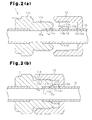
- the pipe 15 is passed through the holding hole 12b of the nut 12 on the inner peripheral surface 13b of the sleeve 13, thereby inserting a distal end portion 15a of the pipe 15 into the joint hole 11a of the joint body 11 (second step).
- the internal thread portion 12a of the nut 12 is screwed onto the external thread portion 11b of the joint body 11.
- the guide face 11c of the joint body 11 is brought into contact with the front end portion 13a of the sleeve 13, and the inner surface 12c of the nut 12 is brought into contact with the rear end surface 13d of the sleeve 13.
- the rear end surface 13d of the sleeve 13 receives pressing force from the inner surface 12c of the nut 12, so that the outer peripheral surface 13c of the sleeve 13 is guided on the guide face 11c of the joint body 11. This allows the front end portion 13a of the sleeve 13 to bite into the outer peripheral surface 15b of the pipe 15 as shown in Fig. 2(b) (third step). Thus, the pipe 15 is connected to the joint hole 11a of the joint body 11.
- the partition cover 2 can be removed from the pipe joint 1 and then the pipe 15 can be connected to the pipe joint 1 by simply removing and then tightening the nut 12. Furthermore, with the partition cover 2 mounted on the pipe joint 1, the sleeve 13 is not deformed, and thus air tightness can be ensured at the biting portion of the sleeve 13 when the pipe 15 is connected to the pipe joint 1.
- the second embodiment is the same as the first embodiment in the basic construction of the pipe joint 1, a flareless joint, but different from the first embodiment in how the partition cover 3 is supported with respect to the pipe joint 1.
- the same components as those of the first embodiment will be indicated with the same symbols, and may be described in a simplified manner or not explained repeatedly.
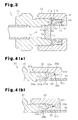
- Fig. 3 is a cross-sectional view illustrating the construction of a pipe joint cover structure according to this embodiment.
- the pipe joint cover structure includes the pipe joint 1 and the partition cover 3 provided to be removable from the pipe joint 1.
- the partition cover 3 is configured to seal the opening 1a of the pipe joint 1 when mounted on the pipe joint 1.
- the partition cover 3 When mounted on the pipe joint 1, the partition cover 3, which is formed of a resin member, is sandwiched between the joint body 11 and the nut 12 as shown in Fig. 3 .
- the partition cover 3 has a fitting portion 3a which fits into the joint hole 11a of the joint body 11 when mounted on the pipe joint 1.
- the partition cover 3 is radially positioned by the fitting portion 3a being fitted into the joint hole 11a.
- the partition cover 3 has a contact face 3b and a press face 3c.
- the contact face 3b is brought into contact with a projection 11h provided on a side face 11g of the joint body 11 or on the side from which the nut 12 is screwed, and the press face 3c is brought into contact with the inner surface 12c of the nut 12.
- the contact face 3b and the press face 3c are brought into contact with the projection 11h and the inner surface 12c, respectively, thereby allowing the partition cover 3 to be positioned in the direction of the nut 12 being screwed.
- the partition cover 3 is supported at the fitting portion 3a, the contact face 3b, and the press face 3c with respect to the pipe joint 1.
- the press face 3c of the partition cover 3 receives pressing force from the inner surface 12c of the nut 12, and the projection 11h of the joint body 11 and the contact face 3b of the partition cover 3 are brought into tight contact with each other, thereby ensuring air tightness between the contact faces.
- the opening 1a of the pipe joint 1 is sealed with the partition cover 3.
- the projection 11h corresponds to the end face of the joint body on the side on which the fastener member is fastened.
- the inner peripheral surface 3d of the partition cover 3, a conical tilted face 3e formed on the inner peripheral surface 3d near the fitting portion 3a, and the inner surface 12c of the nut 12 define a space. As shown in Fig. 3 , this space is configured to be greater than the outer dimensions of the sleeve 13. Accordingly, this allows the partition cover 3 not to press the sleeve 13 when mounted on the pipe joint 1, thereby preventing the sleeve 13 from being deformed.
- the pipe joint cover structure is configured such that the partition cover 3 is sandwiched between the joint body 11 and the nut 12 by the nut 12 being screwed onto the joint body 11, so that the partition cover 3 is mounted without pressing the sleeve 13.
- the aforementioned second embodiment provides the following advantage in addition to the advantages of the items (1), (2), (4), and (5) of the first embodiment.
- a pipe joint 21 according to the third embodiment is configured so that a sleeve 33 is integrated with a nut 32 before piping connection, and the nut 32 is screwed onto a joint body 31, thereby allowing the sleeve 33 to be cut off and thus separated from the nut 32.
- the pipe joint cover structure according to the present invention is applied to the pipe joint 21 constructed in this manner.
- the same components as those of the first embodiment will be indicated with the same symbols, and may be described in a simplified manner or not explained repeatedly.
- the pipe joint 21 includes the joint body 31 to be connected with a pipe, the nut 32 serving as a fastener member to be screwed onto the joint body 31, and the sleeve 33 to be interposed between the joint body 31 and the nut 32 upon connection of a pipe.
- the sleeve 33 is integrated with the nut 32, such that the sleeve 33 and the nut 32 are coupled to each other via a base portion 33e.
- the pipe 34 is permitted to pass through a holding hole 32b of the nut 32, thereby inserting a distal end portion 34a of the pipe 34 into a joint hole 31a of the joint body 31. Then, an internal thread portion 32a of the nut 32 is screwed onto an external thread portion 31b of the joint body 31 ( Fig. 4(a) ).
- the guide face 31c of the joint body 31 is brought into contact with the front end portion 33a of the sleeve 33, while an inner surface 32c of the nut 32 is brought into contact with a rear end surface 33d of the sleeve 33.
- the rear end surface 33d of the sleeve 33 receives a pressing force from the inner surface 32c of the nut 32, so that the outer peripheral surface 33c of the sleeve 33 is guided on the guide face 31c of the joint body 31.
- This will cause the front end portion 33a of the sleeve 33 to bite into the outer peripheral surface 34b of the pipe 34 ( Fig. 4(b) ).
- the pipe joint 21 connects the pipe 34 to the joint body 31 by permitting the front end portion 33a of the sleeve 33 to bite into the outer peripheral surface 34b of the pipe 34.
- FIG. 5 is a cross-sectional view illustrating the construction of a pipe joint cover structure according to this embodiment.
- the pipe joint cover structure includes the aforementioned pipe joint 21, and a partition cover 22 provided to be removable from the pipe joint 21.
- the partition cover 22 is configured to seal the opening 21a of the pipe joint 21 when mounted on the pipe joint 21.
- the partition cover 22 When mounted on the pipe joint 21, the partition cover 22, which is formed of a resin member, is sandwiched between the joint body 31 and the nut 32 as shown in Fig. 5 .
- the partition cover 22 has a fitting portion 22a which fits into the joint hole 31a of the joint body 31 when mounted on the pipe joint 21.
- the partition cover 22 is radially positioned by the fitting portion 22a being fitted into the joint hole 31a.
- the partition cover 22 has a conical contact face 22b and a press face 22c.
- the press face 22c of the partition cover 22 is configured to be brought into contact with the side face 33f, which is radially outside of the base portion 33e of the sleeve 33 which is to be cut off during piping connection. This prevents the sleeve 33 from being cut off the nut 32 due to a pressing force by the press face 22c during the mounting of the partition cover 22.
- the partition cover 22 is positioned in the direction of the nut 32 being screwed by the contact face 22b and the guide face 31c being brought into contact with each other and by the press face 22c and the side face 33f being brought into contact with each other. In this manner, the partition cover 22 is supported at the fitting portion 22a, the contact face 22b, and the press face 22c with respect to the pipe joint 21.
- the side face 33f corresponds to a surface of the fastener member formed substantially perpendicular to the fastening direction.
- the inner peripheral surface 22d of the partition cover 22 is configured so not to contact with the outer peripheral surface 33c of the sleeve 33. Accordingly, the sleeve 33 can be made free from pressing force when the partition cover 22 is mounted on the pipe joint 21, thereby preventing the sleeve 33 from being deformed.
- the fitting portion 22a of the partition cover 22 is fitted into the joint hole 31a of the joint body 31.
- the internal thread portion 32a of the nut 32 is screwed onto the external thread portion 31b of the joint body 31. This allows the side face 33f of the sleeve 33 and the press face 22c of the partition cover 22 to be brought into contact with each other, thereby pressing the partition cover 22 in the screwing direction.
- the guide face 31c of the joint body 31 and the contact face 22b of the partition cover 22 are brought into contact with each other, thereby allowing the partition cover 22 to be mounted on the pipe joint 21.
- the side face 33f of the sleeve 33 presses the press face 22c of the partition cover 22 causing the guide face 31c of the joint body 31 and the contact face 22b of the partition cover 22 to be brought into tight contact with each other, thereby ensuring air tightness between the contact faces.
- the opening 21a of the pipe joint 21 is sealed with the partition cover 22.
- the partition cover 22 is attached to the joint body 31 and thereafter the nut 32 is tightened securely; however, alternatively, the partition cover 22 may be attached to the nut 32, and thereafter the nut 32 may be tightened securely.
- the pipe joint cover structure is configured such that the partition cover 22 is sandwiched between the joint body 31 and the nut 32 by the nut 32 being screwed onto the joint body 31, so that the partition cover 22 is mounted without pressing the sleeve 33.
- the aforementioned third embodiment provides the following advantages in addition to the advantages of the items (1) to (5) of the first embodiment.
- the fourth embodiment is the same as the third embodiment in the basic construction of the pipe joint 21, a flareless joint, but different from the third embodiment in how a partition cover 23 is supported with respect to the pipe joint 21.
- the same components as those of the third embodiment will be indicated with the same symbols, and may be described in a simplified manner or not explained repeatedly.
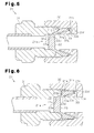
- Fig. 6 is a cross-sectional view illustrating the construction of a pipe joint cover structure according to this embodiment.
- the pipe joint cover structure includes the pipe joint 21, and the partition cover 23 provided to be removable from the pipe joint 21.
- the partition cover 23 is configured to seal the opening 21a of the pipe joint 21 when mounted on the pipe joint 21.
- the partition cover 23 When mounted on the pipe joint 21, the partition cover 23, which is formed of a resin member, is sandwiched between the joint body 31 and the nut 32 as shown in Fig. 6 .
- the partition cover 23 has a fitting portion 23a which fits into the joint hole 31a of the joint body 31 when mounted on the pipe joint 21.
- the partition cover 23 is radially positioned by the fitting portion 23a being fitted into the joint hole 31a.
- the partition cover 23 has a contact face 23b and a press face 23c.
- the contact face 23b is brought into contact with a projection 31h provided on a side face 31g of the joint body 31 or on the side from which the nut 32 is screwed, and the press face 23c is brought into contact with the side face 33f of the sleeve 33.
- the partition cover 23 is positioned in the direction of the nut 32 being screwed, by the contact face 23b and the projection 31h being brought into contact with each other and by the press face 23c and the side face 33f being brought into contact with each other. In this manner, the partition cover 23 is supported at the fitting portion 23a, and the contact face 23b, and the press face 23c with respect to the pipe joint 21.
- the press face 23c of the partition cover 23 receives pressing force from the side face 33f of the sleeve 33, and the projection 31h of the joint body 31 and the contact face 23b of the partition cover 23 are brought into tight contact with each other, thereby ensuring air tightness between the contact faces.
- the opening 21a of the pipe joint 21 is sealed with the partition cover 23.
- the projection 31h corresponds to the end face of the joint body on the side on which the fastener member is fastened.
- the inner peripheral surface 23d of the partition cover 23 is configured so as not to contact with the outer peripheral surface 33c of the sleeve 33. Accordingly, the sleeve 33 is made free from pressure when the partition cover 23 is mounted on the pipe joint 21, thereby preventing the sleeve 33 from being deformed.
- the pipe joint cover structure is configured such that the partition cover 23 is sandwiched between the joint body 31 and the nut 32 by the nut 32 being screwed onto the joint body 31, so that the partition cover 23 is mounted without pressing the sleeve 33.
- the aforementioned fourth embodiment provides the advantages of the items (7) and (8) of the third embodiment in addition to the effect of the second embodiment.
- the pipe joint 21 is constructed so that the sleeve 33 is integrated with the nut 32.
- the sleeve 33 is connected to the nut 32 with adhesive or by snap-fit.
- the pipe joint 21 is constructed so that the sleeve 33 is integrated with the nut 32.
- the sleeve 33 is integrated with the joint body 31, and the nut 32 is screwed onto the joint body 31, thereby allowing the sleeve 33 to be cut off and thus separated from the joint body 31.
- the partition cover 2, 3, 22, or 23 is formed of a resin member; however, it may also be formed of a material other than a resin material, e.g., of metal.
- the sleeve 13 or 33 is configured to receive no pressing force from the partition cover 2, 3, 22, or 23 when mounted on the pipe joint 1 or 21.
- the partition cover 2, 3, 22, or 23 may also be constructed that the sleeve 13 or 33 receives pressing force.
- Fig. 7 is a cross-sectional view illustrating a pipe joint cover structure applied to the pipe joint 1 in which a partition cover is mounted with pressing force acting upon the sleeve.
- the pipe joint cover structure includes the pipe joint 1, and a partition cover 5 provided to be removable from the pipe joint 1.
- the partition cover 5 when mounted on the pipe joint 1, the partition cover 5 is sandwiched between the joint body 11 and the nut 12.
- a conical tilted face 5e facing the outer peripheral surface 13c of the sleeve 13 is brought into contact with part of the outer peripheral surface 13c to elastically press the sleeve 13.
- the partition cover 5 is mounted on the pipe joint 1 in a manner that the partition cover 5 elastically deforms to thereby prevent the sleeve 13 from being changed in shape even when the sleeve 13 receives pressing force.
- the partition cover 5 is not brought into contact with the front end portion 13a of the sleeve 13 even when the sleeve 13 is deformed due to the mounting of the partition cover 5. It is thus possible not to affect the front end portion 13a of the sleeve 13 which bites into a pipe. Accordingly, regardless of whether the sleeve 13 is deformed, it is possible to ensure air tightness during the pipe connection when the pipe joint 1 is used for piping connection.
- the pipe joint 1 or 21 is constructed so that the nut 12 or 32 is screwed onto the joint body 11 or 31 to thereby connect a pipe to the joint body 11 or 31.
- a pipe may also be connected to the joint body without using screw thread structure between the joint body and the nut.
- Fig. 8 is a cross-sectional view illustrating a pipe joint cover structure in which no screw thread structure is used for a pipe joint.
- This pipe joint cover structure includes a pipe joint 41, and the partition cover 2 constructed in the same manner as in the first embodiment.
- the pipe joint 41 includes a joint body 42 into which a pipe is inserted, a fastener member 43 to be fastened to the joint body 42, and a sleeve 44 to bite into the outer peripheral surface of the pipe.
- An actuating lever 45 is rotatably supported on the outer periphery of the joint body 42.
- a lock lever 46 is rotatably supported.
- a pivot shaft 46a of the lock lever 46 is disposed parallel to a pivot shaft 45a of the actuating lever 45.
- a lock pawl 46b provided on an end of the lock lever 46 is configured to engage a projected portion 43a provided on the outer peripheral surface of the fastener member 43.
- a cylindrical sliding face 42a provided on the joint body 42 engages a sliding face 43b provided on the fastener member 43, and is configured to allow the fastener member 43 to move only in the axial direction of the joint body 42.
- the actuating lever 45 is rotated in direction R to thereby connect the fastener member 43 to the joint body 42, allowing the sleeve 44 to bite into the outer periphery of the pipe.
- Such a pipe joint 41 can also be constructed that the fastener member 43 is connected to the joint body 42 allowing the partition cover 2 to be sandwiched between the joint body 42 and the fastener member 43, thereby sealing the opening 41a of the pipe joint.
- the first to fourth embodiments are constructed so that when the partition cover 2, 3, 22, or 23 is mounted on the pipe joint 1 or 21, the partition cover 2, 3, 22, or 23 is sandwiched between the joint body 11 or 31 and the nut 12 or 32. However, it may also be constructed that a partition cover is screwed into the joint body, thereby sealing the opening 1a or 21a.
- Fig. 9 is a cross-sectional view illustrating a pipe joint cover structure in which this arrangement is applied to the pipe joint 1. There is formed an internal thread portion 11j on an inner peripheral surface 11i of the joint body 11 that forms the opening 1a of the pipe joint 1.
- a partition cover 4 is formed in a cylindrical shape and has an outer peripheral surface on which is provided an external thread portion 4a to be screwed into the internal thread portion 11j.
- the external thread portion 4a is formed to have a thread pitch that gradually changes, and is constructed so that when the external thread portion 4a is screwed into the internal thread portion 11j, their threads engage each other to maintain air tightness.
- a screwdriver or the like is inserted into a groove portion 4b of the partition cover 4 to screw the partition cover 4 securely. This ensures air tightness between the internal thread portion 11j and the external thread portion 4a and sealing of the opening 1a.
- the partition cover 4 does not contact with the sleeve 13, it is possible to prevent the sleeve 13 from being deformed.
- the external thread portion 4a of the partition cover 4 may include a well-known removable seal thread arrangement with threads coated with an adhesive material.
- the aforementioned pipe joint cover structure may be applied to the pipe joint 21.
- fluid flowing through a pipe connected to the pipe joint 1 or 21 is not limited to a particular type of fluid.
- the pipe joint 1 or 21 of the first to fourth embodiments may be a pipe joint connected with a pipe through which supercritical coolant used under a supercritical state flows.
- a system in which the pipe joint 1 or 21 is used may undergo a pressure-proof test with no pipes connected thereto, in the case of which high pressure may act upon the partition cover 2, 3, 22, or 23 mounted on the pipe joint 1 or 21.
- the aforementioned pipe joint cover structure is configured so that the opening 1a or 21a of the pipe joint 1 or 21 is reliably sealed. Accordingly, even when high pressure acts during such a pressure-proof test, it is possible to reliably prevent leakage of coolant from between the pipe joint 1 or 21 and the partition cover 2, 3, 22, or 23.
- the pipe joint of the first to fourth embodiments may be used as a pipe joint to be connected with a pipe through which carbon dioxide coolant flows.
- the fluid flowing through the pipe is carbon dioxide coolant
- the pipe circuit using the pipe joint 1 or 21 ia friendly to the global environment.
- high pressure may act upon the partition cover during a pressure-proof test when the carbon dioxide coolant is used under a supercritical state.
- the aforementioned pipe joint cover structure ensures that the opening 1a or 21a of the pipe joint 1 or 21 is sealed, it is possible to reliably prevent leakage of coolant from between the pipe joint 1 or 21 and the partition cover 2, 3, 22, or 23.
- the pipe joint of the first to fourth embodiments may be a pipe joint to be connected with a pipe through which hydrocarbon coolant flows.
- the fluid flowing through the pipe is hydrocarbon coolant such as propane or isobutane
- the pipe circuit using the pipe joint 1 or 21 is friendly to the global environment.
- the aforementioned pipe joint cover structure ensures that the opening 1a or 21a of the pipe joint 1 or 21 is sealed. Accordingly, when the system using the pipe joint 1 or 21 undergoes a pressure-proof test with no pipes connected thereto, it is possible to reliably prevent leakage of highly flammable hydrocarbon coolant from between the pipe joint 1 or 21 and the partition cover 2, 3, 22, or 23.
- the pipe joint cover structure is applied to the pipe joint 1 or 21 to which two pipes are connected.
- this pipe joint cover structure may be applied to connections 55 and 56 of a coolant pipe 54 that communicates between an indoor unit 52 and an outdoor unit 53 of an air conditioner 51 as shown in Fig. 10 .
- the partition cover 2, 3, 22, or 23 is mounted on the pipe joint 1 or 21 provided at the connections 55 and 56, the opening 1a or 21a of the pipe joint 1 or 21 can be reliably sealed. Accordingly, when the air conditioner 51 undergoes a pressure-proof test with the partition cover 2, 3, 22, or 23 mounted, it is possible to prevent leakage of coolant from between the pipe joint 1 or 21 and the partition cover 2, 3, 22, or 23.
- the pipe joint cover structure of the first to fourth embodiments may be applied to a connection of a closing valve provided at the connection 56 or a connection of a coolant pipe for a refrigerator other than the air conditioner 51.
- Fig. 11 is a schematic view illustrating a heat pump water heater with pipes connected thereto.
- Fig. 11(a) is a schematic view illustrating a heat pump water heater 61 including one tank.
- the heat pump water heater 61 includes a heat pump unit 71 which pumps heat from outside, and a hot-water storage unit 81 which supplies hot water using the heat pumped by the heat pump unit 71.
- the heat pump unit 71 is constructed of a refrigeration cycle system which has an expansion valve 72, an air heat exchanger 73, a compressor 74, and a water heat exchanger 75.
- a coolant flows through a coolant pipe 76 which connects between each component.
- the hot-water storage unit 81 is configured so that water supplied to a tank 83 via a feed water pipe 82 is allowed to circulate by a pump 84 between the tank 83 and the water heat exchanger 75.
- the hot-water storage unit 81 is also configured such that hot water heat-exchanged through the water heat exchanger 75 is supplied from the tank 83 via a feed water pipe 85.
- Fig. 11(b) is a schematic view illustrating a heat pump water heater 62 constructed of two tanks.
- the heat pump water heater 62 is constructed in the same manner as the heat pump water heater 61 except that the tank of a hot-water storage unit 91 has a first tank 92 and a second tank 93 connected in series. Furthermore, hot water stored in the first tank 92 and the second tank 93 is allowed to circulate by a pump 95 to and from a reheating-use heat exchanger 94. There is provided a reheating function by which hot water fed by a pump 98 from a bathtub 96 via a feed water pipe 97 is heated through heat exchange in the reheating-use heat exchanger 94 and then fed back to the bathtub 96 via a feed water pipe 99.
- the pipe joint cover structure of the first to fourth embodiments can be applied to a connection 77 disposed in the coolant pipe 76 or a connection 86 disposed in feed water pipes 82 and 85. Furthermore, in the heat pump water heater 62, the pipe joint cover structure of the first to fourth embodiments can also be applied to a connection 100 additionally disposed in feed water pipes 97 and 99. This allows for ensuring sealing of the opening 1a or 21a of the pipe joint 1 or 21 when the partition cover 2, 3, 22, or 23 is mounted on the pipe joint 1 or 21 provided at the connection 77, 86, or 100. It is thus possible to maintain air tightness during a pressure-proof test or transportation of the heat pump water heaters 61 and 62.
- the sleeve 13 or 33 is prevented from being deformed when the partition cover 2, 3, 22, or 23 is mounted on the pipe joint 1 or 21. This allows for ensuring air tightness during a pipe connection when a pipe is connected to the pipe joint 1 or 21.
- the aforementioned connections 77, 86, and 100 may also be differently located depending on the positions of the components or units that constitute the heat pump water heater.
- the aforementioned pipe joint cover structure can be applied to a feed water pipe connection through which water flows.
- the aforementioned pipe joint cover structure can also be applied to a connection of feed water pipe formed of resin.
- the pipe connection method discussed in the first embodiment may be applied to carry out on-site piping installation of the aforementioned air conditioner 51 or the heat pump water heaters 61 and 62.
- Use of this method for the on-site piping installation allows the partition cover 2 to be kept mounted on the pipe joint 1 until piping connection, e.g., during transportation, thereby preventing the intrusion of dust particles or moisture.
- the on-site piping installation can be carried out by the nut 12 being removed and screwed. It is thus possible to provide an on-site piping installation method by which the on-site piping installation can be easily conducted without using special devices or tools.
Landscapes
- Engineering & Computer Science (AREA)
- General Engineering & Computer Science (AREA)
- Mechanical Engineering (AREA)
- Joints With Pressure Members (AREA)
- Mutual Connection Of Rods And Tubes (AREA)
- Protection Of Pipes Against Damage, Friction, And Corrosion (AREA)
Abstract
Description
- The present invention relates to a pipe joint cover structure in which with no pipe connected to a pipe joint, a partition cover constructed to be removable from the pipe joint seals the opening of the pipe joint. The present invention also relates to the partition cover used in the cover structure, a refrigerator using the cover structure, and a pipe connection method.
- Conventionally, various types of pipe joints have been used for connection of pipes, such as refrigerator coolant pipes, through which a fluid flows. Examples of typical pipe joints include a flare joint and a flareless joint (e.g., see Patent Document 1). As shown in
Fig. 12(a) , the flare joint includes ajoint body 101 and anut 102 screwed onto thejoint body 101. Apipe 103 is connected to thejoint body 101 such that its flaredend portion 103a is disposed between a conical face 101a provided on thejoint body 101 and a conical face 102a provided on thenut 102. Then, thenut 102 is screwed onto thejoint body 101 to sandwich theend portion 103a between each of the conical faces 101a and 102a, thereby connecting between thepipe 103 and thejoint body 101. - On the other hand, as shown in
Fig. 13(a) , the flareless joint includes ajoint body 111, anut 112 screwed onto thejoint body 111, and asleeve 113 interposed between thejoint body 111 and thenut 112. Apipe 114 is connected to thejoint body 111 such that its distal end portion 114a is inserted into a joint hole 111a formed on the inner periphery of thejoint body 111. Then, thenut 112 is screwed onto thejoint body 111 allowing thesleeve 113 to be deformed by aconical guide face 111b provided on the inner periphery of thejoint body 111. Afront end portion 113a thus bites into anouter periphery 114b of thepipe 114, thereby connecting between thepipe 114 and the joint body. - For example, those refrigerators that include such pipe joints may undergo a pressure-proof test before piping connection or require the prevention of dust particles or moisture intrusion before piping connection, e.g., during transportation. For this reason, the openings of those pipe joints need to be kept sealed. To this end, with no pipe connected to a pipe joint, such a cover structure is configured that allows the opening of the pipe joint to be sealed with a partition cover constructed to be removable from the pipe joint. For example, in a flare joint cover structure shown in
Fig. 12(b) , apartition cover 105 may be made of pressed parts such as a copper plate, so that thepartition cover 105 is interposed between the conical face 101a of thejoint body 101 and the conical face 102a of thenut 102, both of which are formed to sandwich thepipe 103 therebetween. Then, thenut 102 is tightened securely to sandwich thepartition cover 105 between the conical faces 101a and 102a, thereby ensuring air tightness at acontact face 105a between the conical face 101a and thepartition cover 105. The opening of the pipe joint is thus sealed.
Patent Document 1: Japanese Laid-Open Patent Publication No.2003-74768 - When the aforementioned pipe joint cover structure for the flare joint is applied to the flareless joint, the following problems may be raised.
Fig. 13(b) shows the arrangement of the flareless joint where apartition cover 115 is arranged between thejoint body 111 and thesleeve 113. With thepartition cover 115 installed in this manner, thenut 112 may be tightened securely, thereby ensuring air tightness at acontact face 115a between theguide face 111b and thepartition cover 115. In this case, thepartition cover 115 presses thesleeve 113, possibly causing thesleeve 113 to deform. With thesleeve 113 deformed in this manner, removal of thepartition cover 115 for connection of a pipe may possibly raise a problem that thedeformed sleeve 113 is not available for use or use of thedeformed sleeve 113 leads to a decrease in air tightness after piping connection. - The invention was developed in view of these problems. It is therefore an objective of the present invention to provide a pipe joint cover structure which ensures sealing of the opening of a pipe joint or a flareless joint and prevent a sleeve from being deformed when a partition cover is mounted on the pipe joint which is a flareless joint. It is also an objective of the invention to provide the partition cover used in the cover structure, a refrigerator or the like using the cover structure, and a pipe connection method.
- A pipe joint cover structure according to the present invention is configured so that with no pipe connected to a pipe joint, a partition cover constructed to be removable from the pipe joint seals the opening of the pipe joint. The pipe joint includes a joint body through which a joint hole to be connected with a pipe is formed, a fastener member to be fastened to the joint body, and a sleeve that is caused to bite into an outer periphery of the pipe by the fastener member being fastened to the joint body with the pipe having been inserted into the joint hole. The fastener member being fastened to the joint body allows the partition cover to be sandwiched between the joint body and the fastener member, and mounted on the pipe joint without affecting the portion of the sleeve biting into the pipe.
- According to this arrangement, the partition cover for sealing the opening of the pipe joint which is a flareless joint is sandwiched between the joint body and the fastener member by the fastener member being fastened to the joint body, thereby ensuring sealing of the opening of the pipe joint. Furthermore, the partition cover is mounted on the pipe joint without affecting the portion of the sleeve biting into the pipe, thereby ensuring air tightness during a pipe connection when the pipe joint is used for connection of a pipe. This allows for avoiding such a situation in which when the partition cover is removed for connection of a pipe, the sleeve cannot be used because of its deformation or air tightness is degraded after piping connection because of the sleeve having been deformed. Not to affect the portion of the sleeve biting into in the pipe, the partition cover may be configured not to contact the biting portion of the sleeve during mounting of the partition cover.
- Furthermore, the partition cover may also be mounted on the pipe joint so as not to press the sleeve. According to this arrangement, since the partition cover is mounted on the pipe joint so as not to press the sleeve, it is possible to prevent the sleeve from being deformed due to the mounting of the partition cover. As a result, air tightness is reliably prevented from being degraded after piping connection.
- Furthermore, the partition cover may also be mounted on the pipe joint so as to elastically press the sleeve. According to this arrangement, since the partition cover is mounted on the pipe joint so as to elastically press the sleeve, the sleeve is prevented from being deformed as much as possible due to the mounting of the partition cover.
- Furthermore, the joint body may have a thread portion formed so that the fastener member is screwed onto the thread portion to be thereby fastened to the joint body. According to this arrangement, since the fastener member is fastened to the joint body by being screwed onto the thread portion formed on the joint body, it is possible to ensure that the partition cover is held on the joint body by the fastener member being screwed. This allows for reliably sealing the opening of the pipe joint.
- Furthermore, the joint body of the pipe joint may also have a conical guide face formed to guide the sleeve so that the sleeve is deformed to bite into the outer periphery of the pipe upon connection of the pipe. When mounted on the pipe joint, the partition cover may also be brought into contact with the guide face to seal the opening of the pipe joint.
- According to this arrangement, the joint body of the pipe joint has a conical guide face formed to guide the sleeve so that the sleeve is deformed to bite into the outer periphery of the pipe upon connection of the pipe. Furthermore, when the partition cover is mounted on the pipe joint, the contact face to the guide face maintains air tightness to thereby seal the opening of the pipe joint. Accordingly, when the partition cover is mounted on the pipe joint, the wedge effect provided by the conical guide face and the partition cover can enhance the tightness between the contact faces. It is thus possible to provide increased air tightness between the contact faces and thereby ensure further improved sealing of the opening of the pipe joint.
- Furthermore, when mounted onto the pipe joint, the partition cover may also be brought into contact with an end face of the joint body to which the fastener member is fastened, thereby sealing the opening of the pipe joint.
- According to this arrangement, when mounted on the pipe joint, the partition cover is brought into contact with the end face of the joint body on the side on which the fastener member is fastened, allowing the contact faces to maintain air tightness and thereby seal the opening of the pipe joint. When the partition cover is mounted on the pipe joint, the partition cover is pushed against the end face of the joint body that is opposite to the direction in which the fastener member is fastened, thereby making it possible to provide improved tightness between the contact faces. It is thus possible to provide increased air tightness between the contact faces and thereby ensure further improved sealing of the opening of the pipe joint.
- Furthermore, when mounted onto the pipe joint, the partition cover may be pushed to the joint body by a surface of the fastener member that is formed substantially perpendicular to the fastening direction.
- According to this arrangement, when mounted on the pipe joint, the partition cover is pressed onto the joint body by the plane of the fastener member formed substantially perpendicular to the fastening direction. Accordingly, when the partition cover is mounted on the pipe joint, the partition cover is pushed in the fastening direction to improve tightness of the contact faces between the partition cover and the joint body, thereby providing increased air tightness between the contact faces.
- Furthermore, the pipe joint may also be constructed that the sleeve is integrated with the fastener member before the fastener member is fastened to the joint body, and the fastener member being fastened to the joint body causes the sleeve to be cut off and thus separated from the fastener member.
- According to this arrangement, the aforementioned cover structure can also be used for the pipe joint configured such that the sleeve is integrated with the fastener member before the fastener member is fastened to the joint body, and the fastener member being fastened to the joint body causes the sleeve to be cut off and thus separated from the fastener member. Use of such a pipe joint makes it possible to prevent the sleeve from being lost before piping connection, and thus eliminates the need for storing spare sleeves, in contrast to a conventional case of the sleeve being formed separately from the fastener member. Additionally, during piping connection, the sleeve does not need to be assembled, thereby facilitating the piping connection. For such a pipe joint, the aforementioned cover structure can be configured, thereby ensuring sealing of the opening of the pipe joint.
- Furthermore, the sleeve may also be configured not to be cut off the fastener member when the partition cover is mounted on the pipe joint. According to this arrangement, the sleeve for a pipe joint with the sleeve integrated with the fastener member is configured not to be cut off the fastener member during the mounting of the partition cover on the pipe joint. It is thus possible to avoid such a situation in which the sleeve has already been separated when the pipe joint is used for connection of a pipe. Accordingly, the partition cover is mounted on the pipe joint without impairing the aforementioned effect which is obtained by the sleeve being integrated with the fastener member.
- Furthermore, the partition cover may also be formed of a resin member. According to this arrangement, the partition cover is formed of a resin member. This makes it possible to improve the tightness of the site for sealing the opening of the pipe joint and prevent the sleeve from being accidentally deformed.
- Furthermore, the pipe joint may be a pipe joint connected with a pipe through which a supercritical coolant used under a supercritical state flows. According to this arrangement, the pipe joint is to be connected with a pipe through which a supercritical coolant used under a supercritical state flows. Thus, when a system in which the pipe joint is used undergoes a pressure-proof test with no pipes connected thereto, high pressure may act upon the partition cover mounted on the pipe joint. In this regard, the aforementioned cover structure has the opening of the pipe joint being reliably sealed. Accordingly, even when high pressure acts during such a pressure-proof test, it is possible to reliably prevent leakage of coolant from between the pipe joint and the partition cover.
- Furthermore, the pipe joint may be connected with a pipe through which a carbon dioxide coolant flows. According to this arrangement, since the pipe joint is to be connected with a pipe through which a carbon dioxide coolant flows, the pipe circuit using the pipe joint can be made friendly to the global environment. Furthermore, a system in which the pipe joint is used may undergo a pressure-proof test with no pipes connected thereto, in the case of which high pressure may act upon the mounted partition cover when the carbon dioxide coolant is used under a supercritical state. However, the aforementioned cover structure is configured such that the opening of the pipe joint is reliably sealed, thereby making it possible to reliably prevent leakage of coolant from between the pipe joint and the partition cover during the pressure-proof test.
- Furthermore, the pipe joint may be connected with a pipe through which a hydrocarbon coolant flows. According to this arrangement, since the pipe joint is to be connected with a pipe through which a hydrocarbon coolant flows, the pipe circuit using the pipe joint can be made friendly to the global environment. Furthermore, the aforementioned cover structure is configured to reliably seal the opening of the pipe joint. Accordingly, when the system using the pipe joint undergoes a pressure-proof test with no pipes connected thereto, it is possible to reliably prevent leakage of highly flammable hydrocarbon coolant from between the pipe joint and the partition cover.
- Furthermore, the present invention is not limited to the aforementioned pipe joint cover structure but may also be applied to the partition cover used in the aforementioned pipe joint cover structure.
- Furthermore, a refrigerator according to the present invention is characterized in that the aforementioned pipe joint cover structure is applied to a coolant pipe connection. According to this arrangement, the refrigerator is configured so that the aforementioned pipe joint cover structure is applied to a coolant pipe connection. Accordingly, the refrigerator can be constructed to ensure sealing of the opening of the pipe joint when the partition cover is mounted on the pipe joint. Furthermore, since the sleeve is prevented from being deformed when the partition cover is mounted on the pipe joint, the refrigerator ensures air tightness at the connection of the coolant pipe when the coolant pipe is connected thereto.
- Furthermore, a heat pump water heater according to the present invention is characterized in that the aforementioned pipe joint cover structure is applied to a coolant pipe connection. According to this arrangement, the heat pump water heater is constructed so that the aforementioned pipe joint cover structure is applied to a coolant pipe connection. This makes it possible to implement the heat pump water heater that ensures sealing of the opening of the pipe joint when the partition cover is mounted on the pipe joint. Furthermore, the sleeve is prevented from being deformed when the partition cover is mounted on the pipe joint. This makes it possible to implement a heat pump water heater that ensures air tightness during the connection of the coolant pipe when the coolant pipe is connected thereto.
- Furthermore, a feed water pipe according to the present invention is characterized in that the aforementioned pipe joint cover structure is applied to a pipe connection. According to this arrangement, the feed water pipe is configured so that the aforementioned pipe joint cover structure is applied to a pipe connection. This makes it possible to implement a feed water pipe that ensures sealing of the opening of the pipe joint when the partition cover is mounted on the pipe joint. Furthermore, the sleeve is prevented from being deformed when the partition cover is mounted on the pipe joint. This makes it possible to implement a feed water pipe that ensures air tightness during the connection of the pipe when the pipe is connected.
- Furthermore, a pipe connection method according to the present invention is configured for a pipe joint which uses the aforementioned pipe joint cover structure. The method is characterized by including a first step of removing the fastener member from the joint body to thereby remove the partition cover, a second step of inserting a pipe into the joint hole of the joint body, and a third step of allowing the sleeve to bite into the outer periphery of the pipe by the fastener member being fastened to the joint body.
- According to this arrangement, to connect a pipe to the pipe joint which uses the aforementioned pipe joint cover structure, the fastener member is removed from the joint body to remove the partition cover, and then the pipe is inserted into the joint hole of the joint body. Then, the fastener member is fastened to the joint body, thereby allowing the sleeve to bite into the outer periphery of the pipe. Accordingly, the partition cover can be removed for connection of a pipe simply by removing and fastening the fastener member.
- Furthermore, an on-site piping installation method according to the present invention is characterized in that the aforementioned pipe connection method is applied to carry out on-site piping installation. According to this arrangement, since the partition cover can be kept mounted on the pipe joint until piping connection, e.g., during transportation, dust particles or moisture intrusion can be prevented. Furthermore, since on-site piping installation is carried out by the fastener member being removed and screwed, etc., the on-site piping installation can be conducted without using special devices or tools.
-
-
Fig. 1 is a cross-sectional view illustrating a pipe joint cover structure according to a first embodiment; -
Fig. 2(a) is a cross-sectional view illustrating a pipe joint before a pipe is connected thereto; -
Fig. 2(b) is a cross-sectional view illustrating the pipe joint with a pipe connected thereto; -
Fig. 3 is a cross-sectional view illustrating a pipe joint cover structure according to a second embodiment; -
Fig. 4(a) is a cross-sectional view illustrating a pipe joint integrated with a sleeve with the sleeve yet to be cut off; -
Fig. 4(b) is a cross-sectional view illustrating the pipe joint with the sleeve biting into the pipe; -
Fig. 5 is a cross-sectional view illustrating a pipe joint cover structure according to a third embodiment; -
Fig. 6 is a cross-sectional view illustrating a pipe joint cover structure according to a fourth embodiment; -
Fig. 7 is a cross-sectional view illustrating a pipe joint cover structure in which a partition cover is mounted to press a sleeve; -
Fig. 8 is a cross-sectional view illustrating a pipe joint cover structure in which no screw thread structure is used for a pipe joint; -
Fig. 9 is a cross-sectional view illustrating a pipe joint cover structure according to another embodiment; -
Fig. 10 is a schematic view illustrating coolant pipes connected between an indoor unit and an outdoor unit of an air conditioner; -
Fig. 11(a) is a schematic view illustrating a heat pump water heater with piping; -
Fig. 11(b) is a schematic view illustrating a heat pump water heater of another embodiment with piping; -
Fig. 12(a) is a cross-sectional view illustrating the construction of a conventional flare joint; -
Fig. 12(b) is a cross-sectional view illustrating a conventional flare joint cover structure; -
Fig. 13(a) is a cross-sectional view illustrating the construction of a conventional flareless joint; and -
Fig. 13(b) is a cross-sectional view illustrating a conventional flareless joint cover structure. - Now, with reference to
Fig. 1 , a description will be made of a pipe joint cover structure according to a first embodiment according of the present invention. -
Fig. 1 is a cross-sectional view illustrating the construction of a pipe joint cover structure according to the present embodiment. The pipe joint cover structure is constructed of a pipe joint 1 to be connected with a pipe, and apartition cover 2 provided to be removable from thepipe joint 1. Thepartition cover 2 is configured to seal an opening 1a of the pipe joint 1 when mounted on thepipe joint 1. - The
pipe joint 1 includes ajoint body 11 to be connected with a pipe, anut 12 serving as a fastener member to be screwed onto thejoint body 11, and asleeve 13 to be interposed between thejoint body 11 and thenut 12 upon connection of a pipe. Thepipe joint 1 is a flareless joint. To connect a pipe to thepipe joint 1, the pipe is inserted into ajoint hole 11a formed on the inner periphery of thejoint body 11, and then thenut 12 is screwed onto thejoint body 11. This allows afront end portion 13a of thesleeve 13 to bite into the outer periphery of the pipe, thereby connecting the pipe to thejoint body 11. - The
joint body 11 has thejoint hole 11a into which the connected pipe is inserted, anexternal thread portion 11b onto which thenut 12 is screwed, aguide face 11c for guiding an outerperipheral surface 13c of thesleeve 13 when thesleeve 13 bites into the pipe, and anut portion 11d formed on the outer periphery. - The
joint hole 11a is formed in a cylindrical shape, and has an inner diameter that is substantially equal to the outer diameter of the inserted pipe. Theexternal thread portion 11b has screw threads formed on the outer periphery of thejoint hole 11a to screw into thenut 12. Theguide face 11c is located at the inlet of thejoint hole 11a and formed in a conical shape. This conical face serves to guide the outerperipheral surface 13c of thesleeve 13 when thenut 12 is tightened securely upon connection of a pipe, thereby allowing thefront end portion 13a of thesleeve 13 to bite into the outer peripheral surface of the pipe. Thenut portion 11d is configured to hold thejoint body 11 when thenut 12 is tightened securely. - Furthermore, the
joint body 11 has acylindrical socket portion 11e formed opposite to thejoint hole 11a, with apipe 14 fixed to thesocket portion 11e by brazing or the like. Thesocket portion 11e and thejoint hole 11a communicate with each other, and this communication through hole serves as the opening 1a of thepipe joint 1. - The
nut 12 has aninternal thread portion 12a to be screwed onto theexternal thread portion 11b of thejoint body 11, a holdinghole 12b for holding the outer periphery of the connected pipe, and aninner surface 12c for press forcing thesleeve 13 when thenut 12 is tightened securely upon connection of a pipe. - The
internal thread portion 12a is formed on the inner peripheral surface which is screwed onto thejoint body 11. The holdinghole 12b is formed in a cylindrical shape and has an inner diameter that is substantially equal to the outer diameter of the held pipe. Theinner surface 12c is formed on a side of a projected portion, which forms the holdinghole 12b and is located closer to theinternal thread portion 12a, substantially perpendicular to the direction of thenut 12 being screwed. Theinner surface 12c corresponds to a surface of the fastener member formed substantially perpendicular to the fastening direction. - The
sleeve 13 has thefront end portion 13a which bites into the outer periphery of a pipe upon connection of the pipe, an innerperipheral surface 13b which opposes the pipe connected, the outerperipheral surface 13c which is guided by theguide face 11c of thejoint body 11 when thefront end portion 13a bites in the pipe, and arear end surface 13d to which pressing force is applied when thefront end portion 13a bites into the pipe. - The inner
peripheral surface 13b is formed in a cylindrical shape, and has an inner diameter that is substantially equal to the outer diameter of the connected pipe. The outerperipheral surface 13c is located on the outer peripheral side of the innerperipheral surface 13b, and formed in a conical shape. The conical face of the outerperipheral surface 13c has a tilt angle β which is less than a tilt angle α of the conical face of theguide face 11c of thejoint body 11. Thus, when thenut 12 is tightened securely upon connection of a pipe, thefront end portion 13a of thesleeve 13 is deformed radially inward to thereby bite into the outer peripheral surface of the pipe. Therear end surface 13d is formed opposite to thefront end portion 13a of thesleeve 13 to oppose theinner surface 12c of thenut 12. When thenut 12 is tightened securely upon connection of a pipe, therear end surface 13d receives a pressing force from theinner surface 12c of thenut 12 in the direction of thenut 12 being screwed. - Next, a description will be made of the
partition cover 2 which seals the opening 1a of thepipe joint 1. When mounted on thepipe joint 1, thepartition cover 2, which is formed of a resin member, is sandwiched between thejoint body 11 and thenut 12 as shown inFig. 1 . Thepartition cover 2 has afitting portion 2a which fits into thejoint hole 11a of thejoint body 11 when mounted on thepipe joint 1. Thepartition cover 2 is radially positioned by thefitting portion 2a being fitted into thejoint hole 11a. Furthermore, thepartition cover 2 has aconical contact face 2b and apress face 2c, which are brought into contact with theguide face 11c of thejoint body 11 and theinner surface 12c of thenut 12, respectively, when thepartition cover 2 is mounted on thepipe joint 1. Thecontact face 2b being brought into contact with theguide face 11c and thepress face 2c being brought into contact with theinner surface 12c allow thepartition cover 2 to be positioned in the direction of thenut 12 being screwed. In this manner, thepartition cover 2 is supported at thefitting portion 2a, thecontact face 2b, and thepress face 2c relative to thepipe joint 1. - Furthermore, an inner
peripheral surface 2d of thepartition cover 2, a conical tiltedface 2e formed on the innerperipheral surface 2d near thefitting portion 2a, and theinner surface 12c of thenut 12 define a space. As shown inFig. 1 , this space is configured to be greater than the outer dimensions of thesleeve 13. Accordingly, this allows thepartition cover 2 not to press thesleeve 13 when mounted on thepipe joint 1, thereby preventing thesleeve 13 from being deformed. - To install the
partition cover 2 in thepipe joint 1, first, thefitting portion 2a of thepartition cover 2 is fitted into thejoint hole 11a of thejoint body 11. Next, thesleeve 13 is placed on the innerperipheral surface 2d of thepartition cover 2, and then theinternal thread portion 12a of thenut 12 is screwed onto theexternal thread portion 11b of thejoint body 11. This allows theinner surface 12c of thenut 12 and thepress face 2c of thepartition cover 2 to be brought into contact with each other, causing pressing force onto thepartition cover 2 in the screwing direction. Thus, theguide face 11c of thejoint body 11 and thecontact face 2b of thepartition cover 2 are brought into contact with each other, thereby mounting thepartition cover 2 in thepipe joint 1. At this time, since theinner surface 12c of thenut 12 presses thepress face 2c of thepartition cover 2, theguide face 11c of thejoint body 11 and thecontact face 2b of thepartition cover 2 are brought into tight contact with each other, thereby ensuring air tightness between the contact faces. In this manner, the opening 1a of thepipe joint 1 is sealed with thepartition cover 2. In addition, in the aforementioned method for mounting thepartition cover 2, thepartition cover 2 is attached to thejoint body 11 and thereafter thenut 12 is tightened securely; however, alternatively, thepartition cover 2 may be attached to thenut 12, and thereafter thenut 12 may be tightened securely. - In this manner, the pipe joint cover structure is configured such that the
partition cover 2 is sandwiched between thejoint body 11 and thenut 12 by thenut 12 being screwed onto thejoint body 11, so that thepartition cover 2 is mounted without pressing thesleeve 13. - Now, a description will be made of a pipe connection method for changing the state of the pipe joint 1 from a state in which the
partition cover 2 is mounted as shown inFig. 1 to the pipe joint 1 to a state in which apipe 15 is connected as shown inFig. 2(b) . To connect thepipe 15 to thepipe joint 1, first, theinternal thread portion 12a of thenut 12 is unscrewed from theexternal thread portion 11b of thejoint body 11. Then, thenut 12 is removed from thejoint body 11, and thesleeve 13 and thepartition cover 2 are then removed (first step). - Next, as shown in
Fig. 2(a) , thepipe 15 is passed through the holdinghole 12b of thenut 12 on the innerperipheral surface 13b of thesleeve 13, thereby inserting adistal end portion 15a of thepipe 15 into thejoint hole 11a of the joint body 11 (second step). Then, while thenut portion 11d of thejoint body 11 is being held, theinternal thread portion 12a of thenut 12 is screwed onto theexternal thread portion 11b of thejoint body 11. As thenut 12 is screwed, theguide face 11c of thejoint body 11 is brought into contact with thefront end portion 13a of thesleeve 13, and theinner surface 12c of thenut 12 is brought into contact with therear end surface 13d of thesleeve 13. As thenut 12 is screwed, therear end surface 13d of thesleeve 13 receives pressing force from theinner surface 12c of thenut 12, so that the outerperipheral surface 13c of thesleeve 13 is guided on theguide face 11c of thejoint body 11. This allows thefront end portion 13a of thesleeve 13 to bite into the outerperipheral surface 15b of thepipe 15 as shown inFig. 2(b) (third step). Thus, thepipe 15 is connected to thejoint hole 11a of thejoint body 11. - In this manner, the
partition cover 2 can be removed from thepipe joint 1 and then thepipe 15 can be connected to the pipe joint 1 by simply removing and then tightening thenut 12. Furthermore, with thepartition cover 2 mounted on thepipe joint 1, thesleeve 13 is not deformed, and thus air tightness can be ensured at the biting portion of thesleeve 13 when thepipe 15 is connected to thepipe joint 1. - The following advantages are obtained according to the aforementioned first embodiment.
- (1) When the
partition cover 2 is mounted on thepipe joint 1, thepartition cover 2 is sandwiched between thejoint body 11 and thenut 12 by thenut 12 being screwed onto thejoint body 11. Accordingly, thepartition cover 2 is supported with thefitting portion 2a, thecontact face 2b, and thepress face 2c, thereby ensuring sealing of the opening 1a of thepipe joint 1. - (2) The
partition cover 2 is supported not to press thesleeve 13 when thepartition cover 2 is mounted on thepipe joint 1, thereby making it possible to prevent thesleeve 13 from being deformed by thepartition cover 2 being mounted. That is, thepartition cover 2 is mounted on thepipe joint 1 without affecting thefront end portion 13a of thesleeve 13 serving as the portion biting into a pipe. It is thus possible to avoid such a situation in which thesleeve 13 cannot be used because of its deformation when thepartition cover 2 is removed for connection of a pipe, or air tightness is degraded after piping connection because of thesleeve 13 having been deformed. - (3) When the
partition cover 2 is mounted on thepipe joint 1, thecontact face 2b of thepartition cover 2 is brought into tight contact with theguide face 11c of thejoint body 11. Theconical contact face 2b and theconical guide face 11c are brought into tight contact with each other in this manner. This wedge effect increases the degree of the tight contact. Accordingly, the air tightness between the contact faces is further improved to thereby ensure further improved sealing of the opening 1a of thepipe joint 1. - (4) When the
partition cover 2 is mounted on thepipe joint 1, thepress face 2c of thepartition cover 2 receives a pressing force from theinner surface 12c of thenut 12 formed on substantially perpendicular to the screwing direction. Accordingly, thepartition cover 2 is pushed in the direction of thenut 12 being screwed in order to enhance the tightness between thecontact face 2b of thepartition cover 2 and theguide face 11c of thejoint body 11, thereby providing increased air tightness between the contact faces. - (5) Since the
partition cover 2 is made of a resin member, the tightness between thecontact face 2b of thepartition cover 2 and theguide face 11c of thejoint body 11 is improved. It is also possible to prevent thesleeve 13 from being accidentally deformed. - Next, with reference to
Fig. 3 , a description will be made of a pipe joint cover structure according to a second embodiment of the present invention. The second embodiment is the same as the first embodiment in the basic construction of thepipe joint 1, a flareless joint, but different from the first embodiment in how thepartition cover 3 is supported with respect to thepipe joint 1. In addition, in the embodiments described below, the same components as those of the first embodiment will be indicated with the same symbols, and may be described in a simplified manner or not explained repeatedly. -
Fig. 3 is a cross-sectional view illustrating the construction of a pipe joint cover structure according to this embodiment. The pipe joint cover structure includes thepipe joint 1 and thepartition cover 3 provided to be removable from thepipe joint 1. Thepartition cover 3 is configured to seal the opening 1a of the pipe joint 1 when mounted on thepipe joint 1. - When mounted on the
pipe joint 1, thepartition cover 3, which is formed of a resin member, is sandwiched between thejoint body 11 and thenut 12 as shown inFig. 3 . Thepartition cover 3 has afitting portion 3a which fits into thejoint hole 11a of thejoint body 11 when mounted on thepipe joint 1. Thepartition cover 3 is radially positioned by thefitting portion 3a being fitted into thejoint hole 11a. Furthermore, thepartition cover 3 has acontact face 3b and apress face 3c. When thepartition cover 3 is mounted on thepipe joint 1, thecontact face 3b is brought into contact with aprojection 11h provided on aside face 11g of thejoint body 11 or on the side from which thenut 12 is screwed, and thepress face 3c is brought into contact with theinner surface 12c of thenut 12. Thecontact face 3b and thepress face 3c are brought into contact with theprojection 11h and theinner surface 12c, respectively, thereby allowing thepartition cover 3 to be positioned in the direction of thenut 12 being screwed. In this manner, thepartition cover 3 is supported at thefitting portion 3a, thecontact face 3b, and thepress face 3c with respect to thepipe joint 1. - Furthermore, the
press face 3c of thepartition cover 3 receives pressing force from theinner surface 12c of thenut 12, and theprojection 11h of thejoint body 11 and thecontact face 3b of thepartition cover 3 are brought into tight contact with each other, thereby ensuring air tightness between the contact faces. In this manner, the opening 1a of thepipe joint 1 is sealed with thepartition cover 3. Theprojection 11h corresponds to the end face of the joint body on the side on which the fastener member is fastened. - Furthermore, the inner
peripheral surface 3d of thepartition cover 3, a conical tiltedface 3e formed on the innerperipheral surface 3d near thefitting portion 3a, and theinner surface 12c of thenut 12 define a space. As shown inFig. 3 , this space is configured to be greater than the outer dimensions of thesleeve 13. Accordingly, this allows thepartition cover 3 not to press thesleeve 13 when mounted on thepipe joint 1, thereby preventing thesleeve 13 from being deformed. - In this manner, the pipe joint cover structure is configured such that the
partition cover 3 is sandwiched between thejoint body 11 and thenut 12 by thenut 12 being screwed onto thejoint body 11, so that thepartition cover 3 is mounted without pressing thesleeve 13. - The aforementioned second embodiment provides the following advantage in addition to the advantages of the items (1), (2), (4), and (5) of the first embodiment.
- (6) In the second embodiment, when the
partition cover 3 is mounted on thepipe joint 1, thecontact face 3b of thepartition cover 3 and theprojection 11h of thejoint body 11 are brought into tight contact with each other. In this manner, thecontact face 3b of thepartition cover 3 is pushed against theprojection 11h in the direction opposite to the direction of thenut 12 being screwed, thereby providing increased tightness between the contact faces. Accordingly, the air tightness between the contact faces can be improved to thereby ensure further improved sealing of the opening 1a of thepipe joint 1. - Next, with reference to
Figs. 4 and5 , a description will be made of a pipe joint cover structure according to a third embodiment of the present invention. A pipe joint 21 according to the third embodiment is configured so that asleeve 33 is integrated with anut 32 before piping connection, and thenut 32 is screwed onto ajoint body 31, thereby allowing thesleeve 33 to be cut off and thus separated from thenut 32. In the third embodiment, the pipe joint cover structure according to the present invention is applied to the pipe joint 21 constructed in this manner. In addition, in the embodiment described below, the same components as those of the first embodiment will be indicated with the same symbols, and may be described in a simplified manner or not explained repeatedly. - Now, with reference to
Fig. 4 , a description will be made of the construction of the pipe joint 21 used for this embodiment. The pipe joint 21 includes thejoint body 31 to be connected with a pipe, thenut 32 serving as a fastener member to be screwed onto thejoint body 31, and thesleeve 33 to be interposed between thejoint body 31 and thenut 32 upon connection of a pipe. As shown inFig. 4(a) , thesleeve 33 is integrated with thenut 32, such that thesleeve 33 and thenut 32 are coupled to each other via abase portion 33e. To connect apipe 34 to the pipe joint 21, thepipe 34 is permitted to pass through a holdinghole 32b of thenut 32, thereby inserting adistal end portion 34a of thepipe 34 into ajoint hole 31a of thejoint body 31. Then, aninternal thread portion 32a of thenut 32 is screwed onto anexternal thread portion 31b of the joint body 31 (Fig. 4(a) ). - As the
nut 32 is tightened securely, aguide face 31c of thejoint body 31 is brought into contact with afront end portion 33a of thesleeve 33 with pressing force being increased therebetween as thenut 32 is screwed. This causes an increasing shearing force to act upon thebase portion 33e of thesleeve 33 in the direction of thenut 32 being screwed, with the result that thebase portion 33e of thesleeve 33 is cut off and thus thenut 32 and thesleeve 33 are separated from each other. When thenut 32 is further screwed, theguide face 31c of thejoint body 31 is brought into contact with thefront end portion 33a of thesleeve 33, while aninner surface 32c of thenut 32 is brought into contact with arear end surface 33d of thesleeve 33. Then, as thenut 32 is screwed, therear end surface 33d of thesleeve 33 receives a pressing force from theinner surface 32c of thenut 32, so that the outerperipheral surface 33c of thesleeve 33 is guided on theguide face 31c of thejoint body 31. This will cause thefront end portion 33a of thesleeve 33 to bite into the outerperipheral surface 34b of the pipe 34 (Fig. 4(b) ). In this manner, the pipe joint 21 connects thepipe 34 to thejoint body 31 by permitting thefront end portion 33a of thesleeve 33 to bite into the outerperipheral surface 34b of thepipe 34. - In addition, a description will be made of a pipe joint cover structure that is applied to the pipe joint 21.
Fig. 5 is a cross-sectional view illustrating the construction of a pipe joint cover structure according to this embodiment. The pipe joint cover structure includes the aforementioned pipe joint 21, and apartition cover 22 provided to be removable from the pipe joint 21. Thepartition cover 22 is configured to seal theopening 21a of the pipe joint 21 when mounted on the pipe joint 21. - When mounted on the pipe joint 21, the
partition cover 22, which is formed of a resin member, is sandwiched between thejoint body 31 and thenut 32 as shown inFig. 5 . Thepartition cover 22 has afitting portion 22a which fits into thejoint hole 31a of thejoint body 31 when mounted on the pipe joint 21. Thepartition cover 22 is radially positioned by thefitting portion 22a being fitted into thejoint hole 31a. Furthermore, thepartition cover 22 has aconical contact face 22b and apress face 22c. When thepartition cover 22 is mounted on the pipe joint 21, thecontact face 22b is brought into contact with theguide face 31c of thejoint body 31, and thepress face 22c is brought into contact with aside face 33f of thebase portion 33e of thesleeve 33. Thepress face 22c of thepartition cover 22 is configured to be brought into contact with theside face 33f, which is radially outside of thebase portion 33e of thesleeve 33 which is to be cut off during piping connection. This prevents thesleeve 33 from being cut off thenut 32 due to a pressing force by thepress face 22c during the mounting of thepartition cover 22. Thepartition cover 22 is positioned in the direction of thenut 32 being screwed by thecontact face 22b and theguide face 31c being brought into contact with each other and by thepress face 22c and theside face 33f being brought into contact with each other. In this manner, thepartition cover 22 is supported at thefitting portion 22a, thecontact face 22b, and thepress face 22c with respect to the pipe joint 21. Theside face 33f corresponds to a surface of the fastener member formed substantially perpendicular to the fastening direction. - Furthermore, as shown in
Fig. 5 , the innerperipheral surface 22d of thepartition cover 22 is configured so not to contact with the outerperipheral surface 33c of thesleeve 33. Accordingly, thesleeve 33 can be made free from pressing force when thepartition cover 22 is mounted on the pipe joint 21, thereby preventing thesleeve 33 from being deformed. - To mount the
partition cover 22 on the pipe joint 21, first, thefitting portion 22a of thepartition cover 22 is fitted into thejoint hole 31a of thejoint body 31. Next, theinternal thread portion 32a of thenut 32 is screwed onto theexternal thread portion 31b of thejoint body 31. This allows theside face 33f of thesleeve 33 and thepress face 22c of thepartition cover 22 to be brought into contact with each other, thereby pressing thepartition cover 22 in the screwing direction. Then, theguide face 31c of thejoint body 31 and thecontact face 22b of thepartition cover 22 are brought into contact with each other, thereby allowing thepartition cover 22 to be mounted on the pipe joint 21. At this time, theside face 33f of thesleeve 33 presses thepress face 22c of thepartition cover 22 causing theguide face 31c of thejoint body 31 and thecontact face 22b of thepartition cover 22 to be brought into tight contact with each other, thereby ensuring air tightness between the contact faces. In this manner, theopening 21a of the pipe joint 21 is sealed with thepartition cover 22. In addition, in the aforementioned method for mounting thepartition cover 22, thepartition cover 22 is attached to thejoint body 31 and thereafter thenut 32 is tightened securely; however, alternatively, thepartition cover 22 may be attached to thenut 32, and thereafter thenut 32 may be tightened securely. - In this manner, the pipe joint cover structure is configured such that the
partition cover 22 is sandwiched between thejoint body 31 and thenut 32 by thenut 32 being screwed onto thejoint body 31, so that thepartition cover 22 is mounted without pressing thesleeve 33. - The aforementioned third embodiment provides the following advantages in addition to the advantages of the items (1) to (5) of the first embodiment.
- (7) The pipe joint 21 is constructed so that the
sleeve 33 is integrated with thenut 32 before piping connection, and thenut 32 is screwed onto thejoint body 31, thereby allowing thesleeve 33 to be cut off and thus separated from thenut 32. Accordingly, in contrast to thesleeve 33 formed separately from thenut 32, it is possible to prevent thesleeve 33 from being lost before piping connection, and thus it is not necessary to storespare sleeves 33. Furthermore, during piping connection, thesleeve 33 does not need to be assembled, thereby facilitating the piping connection. For such a pipe joint 21, it is also possible to mount the pipe joint cover structure which ensures sealing of theopening 21a of the pipe joint 21 and prevents deformation of thesleeve 33. - (8) The
press face 22c of thepartition cover 22 is constructed to be brought into contact with theside face 33f, which is radially outside of thebase portion 33e of thesleeve 33 which is to be cut off during piping connection. This prevents thesleeve 33 from being cut off thenut 32 due to a pressing force by thepress face 22c during the mounting of thepartition cover 22. It is thus possible to avoid such a situation in which the sleeve has already been separated when the pipe joint 21 is used for piping connection. Accordingly, thepartition cover 22 can be mounted on the pipe joint 21 without impairment of the aforementioned advantage (7), which is obtained by thesleeve 33 being integrated with thenut 32. - Next, with reference to
Fig. 6 , a description will be made of a pipe joint cover structure according to a fourth embodiment of the present invention. The fourth embodiment is the same as the third embodiment in the basic construction of the pipe joint 21, a flareless joint, but different from the third embodiment in how apartition cover 23 is supported with respect to the pipe joint 21. In addition, in the embodiment described below, the same components as those of the third embodiment will be indicated with the same symbols, and may be described in a simplified manner or not explained repeatedly. -
Fig. 6 is a cross-sectional view illustrating the construction of a pipe joint cover structure according to this embodiment. The pipe joint cover structure includes the pipe joint 21, and thepartition cover 23 provided to be removable from the pipe joint 21. Thepartition cover 23 is configured to seal theopening 21a of the pipe joint 21 when mounted on the pipe joint 21. - When mounted on the pipe joint 21, the
partition cover 23, which is formed of a resin member, is sandwiched between thejoint body 31 and thenut 32 as shown inFig. 6 . Thepartition cover 23 has a fitting portion 23a which fits into thejoint hole 31a of thejoint body 31 when mounted on the pipe joint 21. Thepartition cover 23 is radially positioned by the fitting portion 23a being fitted into thejoint hole 31a. Furthermore, thepartition cover 23 has acontact face 23b and apress face 23c. When thepartition cover 23 is mounted on the pipe joint 21, thecontact face 23b is brought into contact with aprojection 31h provided on a side face 31g of thejoint body 31 or on the side from which thenut 32 is screwed, and thepress face 23c is brought into contact with theside face 33f of thesleeve 33. Thepartition cover 23 is positioned in the direction of thenut 32 being screwed, by thecontact face 23b and theprojection 31h being brought into contact with each other and by thepress face 23c and theside face 33f being brought into contact with each other. In this manner, thepartition cover 23 is supported at the fitting portion 23a, and thecontact face 23b, and thepress face 23c with respect to the pipe joint 21. - Furthermore, the
press face 23c of thepartition cover 23 receives pressing force from theside face 33f of thesleeve 33, and theprojection 31h of thejoint body 31 and thecontact face 23b of thepartition cover 23 are brought into tight contact with each other, thereby ensuring air tightness between the contact faces. In this manner, theopening 21a of the pipe joint 21 is sealed with thepartition cover 23. Theprojection 31h corresponds to the end face of the joint body on the side on which the fastener member is fastened. - Furthermore, as shown in
Fig. 6 , the innerperipheral surface 23d of thepartition cover 23 is configured so as not to contact with the outerperipheral surface 33c of thesleeve 33. Accordingly, thesleeve 33 is made free from pressure when thepartition cover 23 is mounted on the pipe joint 21, thereby preventing thesleeve 33 from being deformed. - In this manner, the pipe joint cover structure is configured such that the
partition cover 23 is sandwiched between thejoint body 31 and thenut 32 by thenut 32 being screwed onto thejoint body 31, so that thepartition cover 23 is mounted without pressing thesleeve 33. - The aforementioned fourth embodiment provides the advantages of the items (7) and (8) of the third embodiment in addition to the effect of the second embodiment.
- In addition, the aforementioned embodiments may be modified as follows.
- In the third and fourth embodiment, the pipe joint 21 is constructed so that the
sleeve 33 is integrated with thenut 32. However, it may also be constructed that thesleeve 33 is connected to thenut 32 with adhesive or by snap-fit. - In the third and fourth embodiment, the pipe joint 21 is constructed so that the
sleeve 33 is integrated with thenut 32. However, it may also be constructed that thesleeve 33 is integrated with thejoint body 31, and thenut 32 is screwed onto thejoint body 31, thereby allowing thesleeve 33 to be cut off and thus separated from thejoint body 31. - In the first to fourth embodiments, the
partition cover - In the first to fourth embodiments, the
sleeve partition cover partition cover front end portion partition cover sleeve Fig. 7 is a cross-sectional view illustrating a pipe joint cover structure applied to the pipe joint 1 in which a partition cover is mounted with pressing force acting upon the sleeve. The pipe joint cover structure includes thepipe joint 1, and apartition cover 5 provided to be removable from thepipe joint 1. As with the first embodiment, when mounted on thepipe joint 1, thepartition cover 5 is sandwiched between thejoint body 11 and thenut 12. When thepartition cover 5 is mounted on thepipe joint 1, a conical tiltedface 5e facing the outerperipheral surface 13c of thesleeve 13 is brought into contact with part of the outerperipheral surface 13c to elastically press thesleeve 13. Accordingly, thepartition cover 5 is mounted on the pipe joint 1 in a manner that thepartition cover 5 elastically deforms to thereby prevent thesleeve 13 from being changed in shape even when thesleeve 13 receives pressing force. Furthermore, thepartition cover 5 is not brought into contact with thefront end portion 13a of thesleeve 13 even when thesleeve 13 is deformed due to the mounting of thepartition cover 5. It is thus possible not to affect thefront end portion 13a of thesleeve 13 which bites into a pipe. Accordingly, regardless of whether thesleeve 13 is deformed, it is possible to ensure air tightness during the pipe connection when thepipe joint 1 is used for piping connection. - In the first to fourth embodiments, the pipe joint 1 or 21 is constructed so that the
nut joint body joint body Fig. 8 is a cross-sectional view illustrating a pipe joint cover structure in which no screw thread structure is used for a pipe joint. This pipe joint cover structure includes a pipe joint 41, and thepartition cover 2 constructed in the same manner as in the first embodiment. The pipe joint 41 includes ajoint body 42 into which a pipe is inserted, afastener member 43 to be fastened to thejoint body 42, and asleeve 44 to bite into the outer peripheral surface of the pipe. Anactuating lever 45 is rotatably supported on the outer periphery of thejoint body 42. At an intermediate position on theactuating lever 45, alock lever 46 is rotatably supported. A pivot shaft 46a of thelock lever 46 is disposed parallel to apivot shaft 45a of the actuatinglever 45. Alock pawl 46b provided on an end of thelock lever 46 is configured to engage a projectedportion 43a provided on the outer peripheral surface of thefastener member 43. Furthermore, acylindrical sliding face 42a provided on thejoint body 42 engages a slidingface 43b provided on thefastener member 43, and is configured to allow thefastener member 43 to move only in the axial direction of thejoint body 42. To use the pipe joint 41 for connection of a pipe, the actuatinglever 45 is rotated in direction R to thereby connect thefastener member 43 to thejoint body 42, allowing thesleeve 44 to bite into the outer periphery of the pipe. Such a pipe joint 41 can also be constructed that thefastener member 43 is connected to thejoint body 42 allowing thepartition cover 2 to be sandwiched between thejoint body 42 and thefastener member 43, thereby sealing theopening 41a of the pipe joint. - The first to fourth embodiments are constructed so that when the
partition cover partition cover joint body nut opening 1a or 21a.Fig. 9 is a cross-sectional view illustrating a pipe joint cover structure in which this arrangement is applied to thepipe joint 1. There is formed an internal thread portion 11j on an inner peripheral surface 11i of thejoint body 11 that forms the opening 1a of thepipe joint 1. Apartition cover 4 is formed in a cylindrical shape and has an outer peripheral surface on which is provided an external thread portion 4a to be screwed into the internal thread portion 11j. The external thread portion 4a is formed to have a thread pitch that gradually changes, and is constructed so that when the external thread portion 4a is screwed into the internal thread portion 11j, their threads engage each other to maintain air tightness. To install thepartition cover 4 in thejoint body 11, a screwdriver or the like is inserted into agroove portion 4b of thepartition cover 4 to screw thepartition cover 4 securely. This ensures air tightness between the internal thread portion 11j and the external thread portion 4a and sealing of the opening 1a. Furthermore, since thepartition cover 4 does not contact with thesleeve 13, it is possible to prevent thesleeve 13 from being deformed. In addition, the external thread portion 4a of thepartition cover 4 may include a well-known removable seal thread arrangement with threads coated with an adhesive material. Furthermore, the aforementioned pipe joint cover structure may be applied to the pipe joint 21. - In the first to fourth embodiments, fluid flowing through a pipe connected to the pipe joint 1 or 21 is not limited to a particular type of fluid. However, the pipe joint 1 or 21 of the first to fourth embodiments may be a pipe joint connected with a pipe through which supercritical coolant used under a supercritical state flows. In such a case, a system in which the pipe joint 1 or 21 is used may undergo a pressure-proof test with no pipes connected thereto, in the case of which high pressure may act upon the
partition cover opening 1a or 21a of the pipe joint 1 or 21 is reliably sealed. Accordingly, even when high pressure acts during such a pressure-proof test, it is possible to reliably prevent leakage of coolant from between the pipe joint 1 or 21 and thepartition cover - Furthermore, the pipe joint of the first to fourth embodiments may be used as a pipe joint to be connected with a pipe through which carbon dioxide coolant flows. In this case, since the fluid flowing through the pipe is carbon dioxide coolant, the pipe circuit using the pipe joint 1 or 21 ia friendly to the global environment. Furthermore, like the aforementioned supercritical coolant, high pressure may act upon the partition cover during a pressure-proof test when the carbon dioxide coolant is used under a supercritical state. However, even in this case, since the aforementioned pipe joint cover structure ensures that the
opening 1a or 21a of the pipe joint 1 or 21 is sealed, it is possible to reliably prevent leakage of coolant from between the pipe joint 1 or 21 and thepartition cover - Furthermore, the pipe joint of the first to fourth embodiments may be a pipe joint to be connected with a pipe through which hydrocarbon coolant flows. In this case, since the fluid flowing through the pipe is hydrocarbon coolant such as propane or isobutane, the pipe circuit using the pipe joint 1 or 21 is friendly to the global environment. Furthermore, the aforementioned pipe joint cover structure ensures that the
opening 1a or 21a of the pipe joint 1 or 21 is sealed. Accordingly, when the system using the pipe joint 1 or 21 undergoes a pressure-proof test with no pipes connected thereto, it is possible to reliably prevent leakage of highly flammable hydrocarbon coolant from between the pipe joint 1 or 21 and thepartition cover - In the first to fourth embodiments, the pipe joint cover structure is applied to the pipe joint 1 or 21 to which two pipes are connected. However, this pipe joint cover structure may be applied to
connections coolant pipe 54 that communicates between anindoor unit 52 and anoutdoor unit 53 of anair conditioner 51 as shown inFig. 10 . In this case, when thepartition cover connections opening 1a or 21a of the pipe joint 1 or 21 can be reliably sealed. Accordingly, when theair conditioner 51 undergoes a pressure-proof test with thepartition cover partition cover air conditioner 51. Furthermore, thesleeve partition cover coolant pipe 54 when thecoolant pipe 54 is connected to the pipe joint 1 or 21. In addition, the pipe joint cover structure of the first to fourth embodiments may be applied to a connection of a closing valve provided at theconnection 56 or a connection of a coolant pipe for a refrigerator other than theair conditioner 51. - Furthermore, the pipe joint cover structure of the first to fourth embodiments may be applied to a connection of a pipe for a heat pump water heater.
Fig. 11 is a schematic view illustrating a heat pump water heater with pipes connected thereto.Fig. 11(a) is a schematic view illustrating a heatpump water heater 61 including one tank. The heatpump water heater 61 includes aheat pump unit 71 which pumps heat from outside, and a hot-water storage unit 81 which supplies hot water using the heat pumped by theheat pump unit 71. Theheat pump unit 71 is constructed of a refrigeration cycle system which has anexpansion valve 72, anair heat exchanger 73, acompressor 74, and awater heat exchanger 75. A coolant flows through acoolant pipe 76 which connects between each component. The hot-water storage unit 81 is configured so that water supplied to atank 83 via afeed water pipe 82 is allowed to circulate by apump 84 between thetank 83 and thewater heat exchanger 75. The hot-water storage unit 81 is also configured such that hot water heat-exchanged through thewater heat exchanger 75 is supplied from thetank 83 via afeed water pipe 85.Fig. 11(b) is a schematic view illustrating a heatpump water heater 62 constructed of two tanks. The heatpump water heater 62 is constructed in the same manner as the heatpump water heater 61 except that the tank of a hot-water storage unit 91 has afirst tank 92 and asecond tank 93 connected in series. Furthermore, hot water stored in thefirst tank 92 and thesecond tank 93 is allowed to circulate by apump 95 to and from a reheating-use heat exchanger 94. There is provided a reheating function by which hot water fed by apump 98 from abathtub 96 via afeed water pipe 97 is heated through heat exchange in the reheating-use heat exchanger 94 and then fed back to thebathtub 96 via afeed water pipe 99. In such heatpump water heaters connection 77 disposed in thecoolant pipe 76 or aconnection 86 disposed infeed water pipes pump water heater 62, the pipe joint cover structure of the first to fourth embodiments can also be applied to aconnection 100 additionally disposed infeed water pipes opening 1a or 21a of the pipe joint 1 or 21 when thepartition cover connection pump water heaters sleeve partition cover aforementioned connections - Furthermore, the pipe connection method discussed in the first embodiment may be applied to carry out on-site piping installation of the
aforementioned air conditioner 51 or the heatpump water heaters partition cover 2 to be kept mounted on the pipe joint 1 until piping connection, e.g., during transportation, thereby preventing the intrusion of dust particles or moisture. Furthermore, the on-site piping installation can be carried out by thenut 12 being removed and screwed. It is thus possible to provide an on-site piping installation method by which the on-site piping installation can be easily conducted without using special devices or tools. - The technical concepts that are conceived from the aforementioned embodiments are listed below in conjunction with their advantages.
- (a) A pipe joint cover structure is configured so that with no pipe connected to a pipe joint, a partition cover constructed to be removable from the pipe joint seals the opening of the pipe joint. The pipe joint includes an internal thread portion on the inner peripheral surface that defines the opening, and the partition cover includes an external thread portion to be screwed into the internal thread portion. The internal thread portion is screwed onto the external thread portion to thereby seal the opening of the pipe joint. The pipe joint cover structure constructed in this manner allows the external thread portion of the partition cover to be screwed into the internal thread portion of the pipe joint, thereby sealing the opening of the pipe joint. It is thus possible to easily mount the partition cover only by forming the internal thread portion on the member that constitutes the opening. Accordingly, a simple structure is used to seal the opening of the pipe joint without affecting the construction of the other members of the pipe joint.
- (b) In the pipe joint cover structure according to the aforementioned (a), the pipe joint includes a joint body having an inner periphery on which a joint hole to be connected with a pipe is formed, and having an outer periphery on which a thread portion is formed. The pipe joint cover structure also includes a nut to be screwed onto the thread portion, and a sleeve that bites into the outer periphery of the pipe by the nut being screwed onto the joint body with the pipe having been inserted into the joint hole. The partition cover is mounted on the pipe joint so as not to press the sleeve. This allows the partition cover sealing the opening of the pipe joint or a flareless joint to be mounted on the pipe joint so as not to press the sleeve. It is thus possible to prevent the sleeve from being deformed due to the mounting of the partition cover. It is thus possible to avoid such a situation in which the sleeve cannot be used because of its deformation when the partition cover is removed for connection of a pipe, or air tightness is degraded after piping connection because of the sleeve having been deformed.
Claims (19)
- A pipe joint cover structure in which with no pipe connected to a pipe joint, a partition cover constructed to be removable from the pipe joint seals an opening of the pipe joint,
the cover structure being characterized in that the pipe joint includes a joint body through which a joint hole to be connected with a pipe is formed, a fastener member to be fastened to the joint body, and a sleeve that is caused to bite into in an outer periphery of the pipe by the fastener member being fastened to the joint body with the pipe having been inserted into the joint hole,
wherein the fastener member fastened to the joint body allows the partition cover to be sandwiched between the joint body and the fastener member, and mounted on the pipe joint without affecting the portion of the sleeve biting into the pipe. - The pipe joint cover structure according to claim 1, characterized in that the partition cover is mounted on the pipe joint so as not to press the sleeve.
- The pipe joint cover structure according to claim 1, characterized in that the partition cover is mounted on the pipe joint so as to elastically press the sleeve.
- The pipe joint cover structure according to claim 1, characterized in that a thread portion is formed on the joint body, and the fastener member is screwed onto the thread portion to be thereby fastened to the joint body.
- The pipe joint cover structure according to claim 1, characterized in that the joint body of the pipe joint has a conical guide face formed to guide the sleeve so that the sleeve is deformed to bite into the outer periphery of the pipe upon connection of the pipe,
wherein, when mounted on the pipe joint, the partition cover is brought into contact with the guide face to seal the opening of the pipe joint. - The pipe joint cover structure according to claim 1, characterized in that, when mounted on the pipe joint, the partition cover is brought into contact with an end face of the joint body to which the fastener member is fastened, thereby sealing the opening of the pipe joint.
- The pipe joint cover structure according to claim 5, characterized in that, when mounted on the pipe joint, the partition cover is pressed onto the joint body by a surface of the fastener member that is formed substantially perpendicular to the fastening direction.
- The pipe joint cover structure according to claim 1, characterized in that the pipe joint is constructed such that the sleeve is integrated with the fastener member before the fastener member is fastened to the joint body, and that the fastener member being fastened to the joint body causes the sleeve to be cut off and thus separated from the fastener member.
- The pipe joint cover structure according to claim 8, characterized in that, when the partition cover is mounted on the pipe joint, the sleeve is not cut off the fastener member.
- The pipe joint cover structure according to claim 1, characterized in that the partition cover is formed of a resin member.
- The pipe joint cover structure according to claim 1,
characterized in that the pipe joint is connected with a pipe through which a supercritical coolant flows used under a supercritical state. - The pipe joint cover structure according to claim 1, characterized in that the pipe joint is connected with a pipe through which a carbon dioxide coolant flows.
- The pipe joint cover structure according to claim 1, characterized in that the pipe joint is connected with a pipe through which a hydrocarbon coolant flows.
- A partition cover used in the pipe joint cover structure according to any one of claims 1 to 13.
- A refrigerator characterized in that the pipe joint cover structure according to any one of claims 1 to 13 is applied to a coolant pipe connection.
- A heat pump water heater characterized in that the pipe joint cover structure according to any one of claims 1 to 13 is applied to a coolant pipe connection.
- A feed water pipe characterized in that the pipe joint cover structure according to any one of claims 1 to 10 is applied to a pipe connection.
- A pipe connection method for a pipe joint using the pipe joint cover structure according to any one of claims 1 to 13, the method being characterized by:a first step of removing the fastener member from the joint body to thereby remove the partition cover;a second step of inserting a pipe into the joint hole of the joint body; anda third step of allowing the sleeve to bite into the outer periphery of the pipe by the fastener member being fastened to the joint body.
- An on-site piping connection method, characterized in that on-site piping connection is carried out by following the pipe connection method according to claim 18.
Applications Claiming Priority (3)
| Application Number | Priority Date | Filing Date | Title |
|---|---|---|---|
| JP2005333302 | 2005-11-17 | ||
| JP2006023472A JP4067016B2 (en) | 2005-11-17 | 2006-01-31 | Pipe joint lid structure, partition lid, refrigeration system, heat pump water heater, water supply piping, piping connection method, and on-site piping construction method |
| PCT/JP2006/322935 WO2007058290A1 (en) | 2005-11-17 | 2006-11-17 | Pipe joint cover structure and pipe connection method |
Publications (2)
| Publication Number | Publication Date |
|---|---|
| EP1950486A1 true EP1950486A1 (en) | 2008-07-30 |
| EP1950486A4 EP1950486A4 (en) | 2013-09-11 |
Family
ID=38048674
Family Applications (1)
| Application Number | Title | Priority Date | Filing Date |
|---|---|---|---|
| EP06832814.5A Withdrawn EP1950486A4 (en) | 2005-11-17 | 2006-11-17 | COVER STRUCTURE FOR PIPE CONNECTION AND METHOD FOR CONNECTING PIPES |
Country Status (8)
| Country | Link |
|---|---|
| US (1) | US8146953B2 (en) |
| EP (1) | EP1950486A4 (en) |
| JP (1) | JP4067016B2 (en) |
| KR (1) | KR100967507B1 (en) |
| CN (1) | CN101305236B (en) |
| AU (1) | AU2006315990B2 (en) |
| TW (1) | TWI306140B (en) |
| WO (1) | WO2007058290A1 (en) |
Cited By (2)
| Publication number | Priority date | Publication date | Assignee | Title |
|---|---|---|---|---|
| EP2302274A4 (en) * | 2008-07-23 | 2013-05-01 | Daikin Ind Ltd | BEND TYPE PIPE CONNECTION STRUCTURE, VALVE USING THIS BEND TYPE PIPE CONNECTION STRUCTURE, BEND TYPE PIPE CONNECTOR, AND FREEZING DEVICE |
| EP3171015A4 (en) * | 2014-07-16 | 2017-08-16 | Usui Kokusai Sangyo Kaisha Limited | Terminal sealing structure for fuel rail for gasoline direct-injection engine |
Families Citing this family (21)
| Publication number | Priority date | Publication date | Assignee | Title |
|---|---|---|---|---|
| JP5326457B2 (en) * | 2007-09-28 | 2013-10-30 | ダイキン工業株式会社 | Biting type pipe connection structure, valve, biting type pipe fitting and refrigeration system |
| EP2198216A4 (en) * | 2007-11-28 | 2013-11-06 | Carrier Corp | Heat exchanger coupling blocking plug |
| JP5320884B2 (en) * | 2008-07-23 | 2013-10-23 | ダイキン工業株式会社 | Biting type pipe connection structure, valve, biting type pipe fitting and refrigeration system |
| JP5359087B2 (en) * | 2008-07-23 | 2013-12-04 | ダイキン工業株式会社 | Biting type pipe connection structure, valve, biting type pipe fitting and refrigeration system |
| JP5320883B2 (en) * | 2008-07-23 | 2013-10-23 | ダイキン工業株式会社 | Biting type pipe connection structure, valve, biting type pipe fitting and refrigeration system |
| JP4557081B2 (en) * | 2009-01-21 | 2010-10-06 | ダイキン工業株式会社 | Biting type pipe connection structure, valve, biting type pipe fitting and refrigeration system |
| CA2763707A1 (en) * | 2009-06-17 | 2010-12-23 | Francis Desmond Lourigan | A end plug |
| US9010766B2 (en) * | 2011-04-11 | 2015-04-21 | DPR Futures LLC | Apparatus and methods for temporarily sealing a pipe |
| KR200456768Y1 (en) | 2011-06-27 | 2011-11-21 | 성기천 | Sealing body for pipe connecting device of air conditioner and pipe connecting device of air conditioner having same |
| JP5851771B2 (en) * | 2011-08-31 | 2016-02-03 | 三菱重工業株式会社 | Supercritical cycle and heat pump water heater using the same |
| FI124681B (en) * | 2011-10-28 | 2014-12-15 | Abloy Oy | Padlock |
| KR102269483B1 (en) * | 2015-05-12 | 2021-06-28 | 엘지전자 주식회사 | Connector for refrigerant pipe |
| CN105135146B (en) * | 2015-10-13 | 2017-03-01 | 天津博益气动股份有限公司 | Mouth plugging apparatus |
| US10221985B2 (en) * | 2016-03-31 | 2019-03-05 | Benjamin H. Ramirez | Pipe cap with transition fitting |
| CN108644502A (en) * | 2018-06-11 | 2018-10-12 | 浙江欧琳生活健康科技有限公司 | A kind of multifunction conic pipe fitting joint |
| JP6822513B2 (en) * | 2018-11-28 | 2021-01-27 | ダイキン工業株式会社 | Fluid unit, refrigeration unit, heat source unit, utilization unit, and refrigeration unit |
| WO2020110413A1 (en) * | 2018-11-28 | 2020-06-04 | ダイキン工業株式会社 | Fluid unit, unit for refrigeration device, heat source unit, usage unit, and refrigeration device |
| JP2020139541A (en) | 2019-02-27 | 2020-09-03 | イハラサイエンス株式会社 | Joint structure |
| US12055244B2 (en) * | 2019-07-03 | 2024-08-06 | Sugjae KANG | Pipe sealing device |
| JP7648929B2 (en) * | 2023-03-29 | 2025-03-19 | ダイキン工業株式会社 | Pipe joint cover |
| CN120958267A (en) * | 2023-03-29 | 2025-11-14 | 大金工业株式会社 | Pipe joint cover |
Family Cites Families (26)
| Publication number | Priority date | Publication date | Assignee | Title |
|---|---|---|---|---|
| US2416829A (en) * | 1944-12-29 | 1947-03-04 | Parker Appliance Co | Closure cap for tube fittings |
| US2625955A (en) * | 1946-03-25 | 1953-01-20 | Parker Appliance Co | Closure cap for tube fittings |
| US2933333A (en) * | 1955-09-26 | 1960-04-19 | Crane Co | Pipe coupling |
| US3036601A (en) * | 1958-10-31 | 1962-05-29 | Dresser Ind | Terminal extension fitting |
| US3070128A (en) * | 1959-06-12 | 1962-12-25 | Parker Hannifin Corp | Closure cap for tube couplings |
| US3425452A (en) * | 1966-02-01 | 1969-02-04 | Carrier Corp | Coupling |
| US3814135A (en) * | 1972-03-02 | 1974-06-04 | Gti Corp | Hose and tubing assembly closures |
| US3951172A (en) * | 1974-11-15 | 1976-04-20 | Josam Manufacturing Co. | Adjustable cleanout plumbing fitting |
| JPS5663Y2 (en) * | 1976-11-11 | 1981-01-06 | ||
| JPS5369015A (en) | 1976-12-01 | 1978-06-20 | Toshiba Corp | Magnetic memory system |
| JPS54149728U (en) * | 1978-04-11 | 1979-10-18 | ||
| US4290276A (en) * | 1979-11-01 | 1981-09-22 | Aeroquip Corporation | Valve with frangible closure |
| US4342337A (en) * | 1980-03-28 | 1982-08-03 | Deere & Company | Protective closure for an article |
| US4915136A (en) * | 1980-10-29 | 1990-04-10 | Proprietary Technology, Inc. | Stuffer plug quick connector assembly |
| US4506705A (en) * | 1982-01-22 | 1985-03-26 | Thompson Ernest R | Pipe closure device |
| JPS6291091U (en) * | 1985-11-29 | 1987-06-10 | ||
| JPS6474384A (en) * | 1987-09-14 | 1989-03-20 | Hitachi Metals Ltd | Resin-coated plug |
| DE4415341A1 (en) * | 1994-05-02 | 1995-11-09 | Teves Gmbh Alfred | Closing device for closing pressure-carrying channels in a housing |
| US6050613A (en) * | 1996-04-01 | 2000-04-18 | Continental Industries, Inc. | Combined plastic pipe coupler and end plug |
| CN2264832Y (en) | 1996-10-18 | 1997-10-15 | 川路塑胶有限公司 | Multi-functional pipe joint |
| JP3915181B2 (en) * | 1997-07-04 | 2007-05-16 | 株式会社富士通ゼネラル | Flare connector sealing device |
| FR2808257B1 (en) * | 2000-04-27 | 2002-09-06 | Novoplastic Sa | SEALING TIP FOR TUBULAR DUCT |
| US7416225B2 (en) * | 2001-02-06 | 2008-08-26 | Swagelok Company | Fitting for metal pipe and tubing |
| JP2003074768A (en) | 2001-08-31 | 2003-03-12 | Daikin Ind Ltd | Pipe fitting structure |
| US7695022B2 (en) * | 2005-06-30 | 2010-04-13 | Eaton Corporation | Fluid coupling cap |
| US7597117B1 (en) * | 2007-03-09 | 2009-10-06 | Carlos Aulet | Compression plug system for tubes and pipes |
-
2006
- 2006-01-31 JP JP2006023472A patent/JP4067016B2/en not_active Expired - Fee Related
- 2006-11-17 AU AU2006315990A patent/AU2006315990B2/en not_active Ceased
- 2006-11-17 KR KR1020087011795A patent/KR100967507B1/en not_active Expired - Fee Related
- 2006-11-17 WO PCT/JP2006/322935 patent/WO2007058290A1/en not_active Ceased
- 2006-11-17 CN CN2006800417206A patent/CN101305236B/en not_active Expired - Fee Related
- 2006-11-17 US US12/084,971 patent/US8146953B2/en not_active Expired - Fee Related
- 2006-11-17 TW TW095142623A patent/TWI306140B/en active
- 2006-11-17 EP EP06832814.5A patent/EP1950486A4/en not_active Withdrawn
Cited By (2)
| Publication number | Priority date | Publication date | Assignee | Title |
|---|---|---|---|---|
| EP2302274A4 (en) * | 2008-07-23 | 2013-05-01 | Daikin Ind Ltd | BEND TYPE PIPE CONNECTION STRUCTURE, VALVE USING THIS BEND TYPE PIPE CONNECTION STRUCTURE, BEND TYPE PIPE CONNECTOR, AND FREEZING DEVICE |
| EP3171015A4 (en) * | 2014-07-16 | 2017-08-16 | Usui Kokusai Sangyo Kaisha Limited | Terminal sealing structure for fuel rail for gasoline direct-injection engine |
Also Published As
| Publication number | Publication date |
|---|---|
| CN101305236B (en) | 2010-08-18 |
| AU2006315990A1 (en) | 2007-05-24 |
| KR100967507B1 (en) | 2010-07-07 |
| JP2007162928A (en) | 2007-06-28 |
| EP1950486A4 (en) | 2013-09-11 |
| TW200728645A (en) | 2007-08-01 |
| AU2006315990B2 (en) | 2010-02-18 |
| WO2007058290A1 (en) | 2007-05-24 |
| TWI306140B (en) | 2009-02-11 |
| CN101305236A (en) | 2008-11-12 |
| KR20080067671A (en) | 2008-07-21 |
| JP4067016B2 (en) | 2008-03-26 |
| US8146953B2 (en) | 2012-04-03 |
| US20090167015A1 (en) | 2009-07-02 |
Similar Documents
| Publication | Publication Date | Title |
|---|---|---|
| AU2006315990B2 (en) | Pipe joint cover structure and pipe connection method | |
| EP1980779B1 (en) | Bite type tube connection structure | |
| KR100983157B1 (en) | Flareless pipe connection structure, flareless pipe connection method, and local pipe connection method | |
| US20090008930A1 (en) | Pipe Fitting | |
| US7971909B2 (en) | Pipe joint, refrigeration device, heat pump hot water supply device, closing valve, water supply piping, method of connecting piping, and in-the field piping method | |
| JP2018146027A (en) | Bite-type fittings and air conditioning systems | |
| KR101153412B1 (en) | Service valve for air conditioning system | |
| JP6822513B2 (en) | Fluid unit, refrigeration unit, heat source unit, utilization unit, and refrigeration unit | |
| JP2004144215A (en) | Water pipe connection structure of heat pump water heater | |
| JP2007211847A (en) | Biting type pipe connection structure, pipe fitting, valve, closing valve, refrigeration cycle device, hot water supply device, biting type pipe connecting method, and local piping connecting method | |
| JP2007218301A (en) | Pipe fittings, refrigeration equipment, heat pump water heater, and water supply piping |
Legal Events
| Date | Code | Title | Description |
|---|---|---|---|
| PUAI | Public reference made under article 153(3) epc to a published international application that has entered the european phase |
Free format text: ORIGINAL CODE: 0009012 |
|
| 17P | Request for examination filed |
Effective date: 20080513 |
|
| AK | Designated contracting states |
Kind code of ref document: A1 Designated state(s): AT BE BG CH CY CZ DE DK EE ES FI FR GB GR HU IE IS IT LI LT LU LV MC NL PL PT RO SE SI SK TR |
|
| DAX | Request for extension of the european patent (deleted) | ||
| A4 | Supplementary search report drawn up and despatched |
Effective date: 20130812 |
|
| RIC1 | Information provided on ipc code assigned before grant |
Ipc: F16L 19/14 20060101ALI20130806BHEP Ipc: F16L 55/115 20060101ALI20130806BHEP Ipc: F16L 19/10 20060101AFI20130806BHEP |
|
| STAA | Information on the status of an ep patent application or granted ep patent |
Free format text: STATUS: THE APPLICATION HAS BEEN WITHDRAWN |
|
| 18W | Application withdrawn |
Effective date: 20150624 |