EP1950458A2 - Motorcycle including belt type continuously variable transmission having resin block belt - Google Patents
Motorcycle including belt type continuously variable transmission having resin block belt Download PDFInfo
- Publication number
- EP1950458A2 EP1950458A2 EP08250291A EP08250291A EP1950458A2 EP 1950458 A2 EP1950458 A2 EP 1950458A2 EP 08250291 A EP08250291 A EP 08250291A EP 08250291 A EP08250291 A EP 08250291A EP 1950458 A2 EP1950458 A2 EP 1950458A2
- Authority
- EP
- European Patent Office
- Prior art keywords
- belt
- transmission casing
- air
- intake duct
- air passage
- Prior art date
- Legal status (The legal status is an assumption and is not a legal conclusion. Google has not performed a legal analysis and makes no representation as to the accuracy of the status listed.)
- Granted
Links
Images








Classifications
-
- B—PERFORMING OPERATIONS; TRANSPORTING
- B62—LAND VEHICLES FOR TRAVELLING OTHERWISE THAN ON RAILS
- B62K—CYCLES; CYCLE FRAMES; CYCLE STEERING DEVICES; RIDER-OPERATED TERMINAL CONTROLS SPECIALLY ADAPTED FOR CYCLES; CYCLE AXLE SUSPENSIONS; CYCLE SIDECARS, FORECARS, OR THE LIKE
- B62K11/00—Motorcycles, engine-assisted cycles or motor scooters with one or two wheels
- B62K11/02—Frames
- B62K11/04—Frames characterised by the engine being between front and rear wheels
-
- B—PERFORMING OPERATIONS; TRANSPORTING
- B62—LAND VEHICLES FOR TRAVELLING OTHERWISE THAN ON RAILS
- B62M—RIDER PROPULSION OF WHEELED VEHICLES OR SLEDGES; POWERED PROPULSION OF SLEDGES OR SINGLE-TRACK CYCLES; TRANSMISSIONS SPECIALLY ADAPTED FOR SUCH VEHICLES
- B62M7/00—Motorcycles characterised by position of motor or engine
- B62M7/02—Motorcycles characterised by position of motor or engine with engine between front and rear wheels
-
- F—MECHANICAL ENGINEERING; LIGHTING; HEATING; WEAPONS; BLASTING
- F16—ENGINEERING ELEMENTS AND UNITS; GENERAL MEASURES FOR PRODUCING AND MAINTAINING EFFECTIVE FUNCTIONING OF MACHINES OR INSTALLATIONS; THERMAL INSULATION IN GENERAL
- F16H—GEARING
- F16H57/00—General details of gearing
- F16H57/02—Gearboxes; Mounting gearing therein
- F16H57/028—Gearboxes; Mounting gearing therein characterised by means for reducing vibration or noise
-
- F—MECHANICAL ENGINEERING; LIGHTING; HEATING; WEAPONS; BLASTING
- F16—ENGINEERING ELEMENTS AND UNITS; GENERAL MEASURES FOR PRODUCING AND MAINTAINING EFFECTIVE FUNCTIONING OF MACHINES OR INSTALLATIONS; THERMAL INSULATION IN GENERAL
- F16H—GEARING
- F16H57/00—General details of gearing
- F16H57/02—Gearboxes; Mounting gearing therein
- F16H57/035—Gearboxes for gearing with endless flexible members
-
- F—MECHANICAL ENGINEERING; LIGHTING; HEATING; WEAPONS; BLASTING
- F16—ENGINEERING ELEMENTS AND UNITS; GENERAL MEASURES FOR PRODUCING AND MAINTAINING EFFECTIVE FUNCTIONING OF MACHINES OR INSTALLATIONS; THERMAL INSULATION IN GENERAL
- F16H—GEARING
- F16H57/00—General details of gearing
- F16H57/04—Features relating to lubrication or cooling or heating
- F16H57/0412—Cooling or heating; Control of temperature
- F16H57/0415—Air cooling or ventilation; Heat exchangers; Thermal insulations
-
- F—MECHANICAL ENGINEERING; LIGHTING; HEATING; WEAPONS; BLASTING
- F16—ENGINEERING ELEMENTS AND UNITS; GENERAL MEASURES FOR PRODUCING AND MAINTAINING EFFECTIVE FUNCTIONING OF MACHINES OR INSTALLATIONS; THERMAL INSULATION IN GENERAL
- F16H—GEARING
- F16H57/00—General details of gearing
- F16H57/04—Features relating to lubrication or cooling or heating
- F16H57/048—Type of gearings to be lubricated, cooled or heated
- F16H57/0487—Friction gearings
- F16H57/0489—Friction gearings with endless flexible members, e.g. belt CVTs
-
- F—MECHANICAL ENGINEERING; LIGHTING; HEATING; WEAPONS; BLASTING
- F16—ENGINEERING ELEMENTS AND UNITS; GENERAL MEASURES FOR PRODUCING AND MAINTAINING EFFECTIVE FUNCTIONING OF MACHINES OR INSTALLATIONS; THERMAL INSULATION IN GENERAL
- F16H—GEARING
- F16H57/00—General details of gearing
- F16H57/02—Gearboxes; Mounting gearing therein
- F16H2057/0203—Gearboxes; Mounting gearing therein the gearbox is associated or combined with a crank case of an engine
-
- F—MECHANICAL ENGINEERING; LIGHTING; HEATING; WEAPONS; BLASTING
- F16—ENGINEERING ELEMENTS AND UNITS; GENERAL MEASURES FOR PRODUCING AND MAINTAINING EFFECTIVE FUNCTIONING OF MACHINES OR INSTALLATIONS; THERMAL INSULATION IN GENERAL
- F16H—GEARING
- F16H57/00—General details of gearing
- F16H57/02—Gearboxes; Mounting gearing therein
- F16H2057/02039—Gearboxes for particular applications
- F16H2057/02043—Gearboxes for particular applications for vehicle transmissions
- F16H2057/02065—Gearboxes for particular applications for vehicle transmissions for motorcycles or squads
Definitions
- the present invention relates to a motorcycle including a belt type continuously variable transmission having a resin block belt.
- a belt type continuously variable transmission includes a primary sheave, a secondary sheave, and a V-belt wound around the primary sheave and the secondary sheave.
- a driving force of a crankshaft of an engine is transmitted in order of the primary sheave, the V-belt, and the secondary sheave.
- the driving force is transmitted to a driving wheel after a speed is changed.
- the primary sheave, the V-belt, and the secondary sheave are housed inside the transmission casing. That is, a belt chamber is formed inside the transmission casing, and the primary sheave, the V-belt, and the secondary sheave are housed in the belt chamber.
- a resin block belt is used in the view of improving a durability of the V-belt and preventing heat generation due to deformation.
- the resin block belt includes a large number of resin blocks, and coupling members for coupling those resin blocks together.
- the resin blocks tend to collide with each other while the V-belt is running. Therefore, the resin block belt tends to cause more noise comparing with a rubber belt.
- JP-A-2002-147582 suggests that a sound absorption material be disposed on an inner surface of the transmission casing for accommodating the resin block belt for the purpose of preventing noise.
- the V-belt runs at a high speed, and the primary sheave and the secondary sheave rotate at high speeds. Therefore, it is necessary to dispose the sound absorption material not to contact with the V-belt and both the sheaves. In other words, it is necessary to dispose the sound absorption material mentioned above at a position with a certain distance away from the V-belt and both the sheaves. Therefore, if the sound absorption material is disposed on the inner surface of the transmission casing as in the motorcycle disclosed in JP-A-2002-147582 , a space for the sound absorption material needs to be provided inside the transmission casing in advance. However, a volume of the belt chamber becomes large if an extra space for the sound absorption material is provided inside the transmission casing. Therefore, the motorcycle disclosed in JP-A-2002-147582 has a problem that the belt type continuously variable transmission itself tends to become large in size.
- a sound absorption material also has a thermal insulation function. Therefore, a temperature inside the belt chamber is apt to rise in the motorcycle disclosed in JP-A-2002-147582 because the sound absorption material is provided on the inner surface of the transmission casing. Thus, there is a problem that a durability of the resin block belt lowers due to a temperature increase in the belt chamber.
- the present invention is made in consideration of the foregoing problems and seeks to provide a noise preventing means suitable for a motorcycle including a belt type continuously variable transmission having a resin block belt.
- An aspect of the present invention provides a motorcycle, including: an engine unit having a transmission casing in which a belt chamber is formed, and a belt type continuously variable transmission housed in the belt chamber and having a resin block belt; a frame member disposed more rearward than or above the transmission casing, extending in a vertical direction or an obliquely upward and downward directions, and supporting at least a part of the engine unit; and an air passage connected to the transmission casing, and constructed with an intake passage for inducting air into the belt chamber or an exhaust passage for discharging air from the belt chamber, in which the air passage extends rearward from the transmission casing passing over the frame member in a side view, and has a curving part curving at a part around the frame member.
- the inventors determined that the noise produced in a belt type continuously variable transmission having a resin block belt is mostly pitch noise caused due to motions of a plurality of resin blocks running one after another, and the pitch noise is a so-called high frequency sound. They noticed that high frequency sound generally has characteristics of high linearity and weak transmission.
- the claimed invention employs a relationship between an air passage for cooling a belt chamber and a reduction of high frequency sounds.
- the air passage of the motorcycle extends rearward from the transmission casing passing over the frame member, and is a long air passage. Therefore, noise of the belt type continuously variable transmission occurred in the belt chamber is damped inside the air passage before it reaches outside. Consequently, noise released outside from the air passage is reduced to a relatively low level.
- the air passage has the curving part curving at a part around the frame member. Thereby, an interruption between the air passage and the frame member can be prevented, and a linear travel of a high frequency sound, which has a high tendency to travel linearly, can be prevented. Accordingly, the motorcycle can effectively prevent high frequency sound that is considered to be a major cause of noise. Therefore, the motorcycle can effectively prevent noise caused by the resin block belt.
- An embodiment of the present invention can provide a noise preventing means suitable for the motorcycle including a belt type continuously variable transmission having a resin block belt.
- a straddle type vehicle is a motorcycle 1.
- the motorcycle 1 includes a vehicle body frame 2 for composing a skeletal structure, and a seat 3 on which a rider (or driver) sits.
- the motorcycle 1 is a so-called off-road type motorcycle.
- a motorcycle according to the present invention is not limited to this, but can be a motorcycle other than an off-road type (such as on-road type, scooter type, or so-called moped type motorcycle).
- the directions of front and rear, and right and left are the directions in the view of a rider sitting on the seat 3 in the following descriptions.
- FIG. 2 is a perspective view viewing the vehicle body frame 2 from the left front.
- the vehicle body frame 2 includes a head pipe 4, a down tube 5 extending downward from the head pipe 4, and a main tube 6 extending rearward from the head pipe 4 above the down tube 5.
- the main tube 6 extends rearward from the head pipe 4.
- a midway part of the main tube 6 bifurcates into a left seat pillar 6L extending leftward and a right seat pillar 6R extending rightward.
- These seat pillars 6L and 6R are formed into a generally transversely symmetrical shape, and make a pair.
- Each of the seat pillars 6L and 6R curves in the rear of the bifurcating part, and extends downward.
- Seat rails 7L and 7R are connected to vicinities of the curving parts of the respective seat pillars 6L and 6R.
- the seat rails 7l and 7R extend rearward.
- Rear ends of buckstays 8L and 8R are connected to the respective seat rails 7L and 7R.
- Front ends of the buckstays 8L and 8R are connected to bottom ends of the respective seat pillars 6L and 6R.
- a pivot part 6a into which a pivot shaft 10 mentioned below is inserted is provided at a bottom end of each of the seat pillars 6L and 6R.
- a rear arm 9 described below is coupled to the pivot part 6a.
- the rear arm 9 includes a generally U-shaped arm part 9a formed to open rearward, and a generally U-shaped coupling part 9b formed to open forward.
- a pipe 9c is provided on an end of each of right and left branches of the coupling part 9b.
- the pivot shaft 10 mentioned above passes through the right and left pivot parts 6a and the right and left pipes 9c. Thereby, the rear arm 9 is swingably coupled to the bottom ends of the seat pillars 6L and 6R via the pivot shaft 10.
- the pivot shaft 10 is formed with a long bolt, and a left end of the pivot shaft 10 is fixed by a nut 10a.
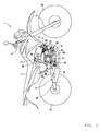
- a front fork 11 (see FIG. 1 ) is inserted into the head pipe 4. As shown in FIG. 1 , a front wheel 12 is supported by the front fork 11. A rear wheel 13 is supported by a bottom part of the arm part 9a of the rear arm 9. Also, a cover 14 for covering the vehicle body frame 2 is disposed above the vehicle body frame 2. The seat 3 mentioned above is disposed slightly more rearward than a center of the cover 14.
- FIG. 3 is a right side view showing a part of FIG. 1 (a construction of each part around the vehicle body frame 2).
- an engine unit 15 for driving the rear wheel 13 (see FIG. 1 ) is suspended on the vehicle body frame 2.
- the engine unit 15 is disposed among the down tube 5 and the seat pillars 6L and 6R, and fixed to the down tube 5 and each of the seat pillars 6L and 6R.
- the engine unit 15 includes an engine 16 and a belt type continuously variable transmission 17 (hereinafter referred to as CVT 17) (see FIG. 5 ). This part will be described in detail below.
- the engine 16 includes a crankcase 20, a cylinder 21, and a cylinder head 22.
- the CVT 17 is housed in a transmission casing 36 connected to the crankcase 20.
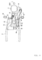
- FIG. 4 is a plan view showing a layout around the seat pillars 6L and 6R.
- rear cushion unit 30 is provided at a center in the vehicle width direction.
- the rear cushion unit 30 is provided in a manner such that it is positioned between the main tube 6 and the rear arm 9 and couples the main tube 6 and the rear arm 9 together.
- the motorcycle 1 of this embodiment includes only one rear cushion unit 30, and has a so-called mono suspension construction.
- the rear cushion unit 30 is not limited to a rear cushion unit directly coupled to the rear arm 9, but can be a rear cushion unit coupled to the rear arm 9 via a link.
- An end of an intake duct 71 for inducting cooling air into a belt chamber 38 (see FIG. 5 ) in the transmission casing 36 is connected to a front half part of the transmission casing 36.
- the intake duct 71 extends upward from the transmission casing 36, then curves, and extends rearward passing over the seat pillar 6R.
- An air chamber 94 is connected to a rear end of the intake duct 71.
- An air filter (not shown) is disposed inside the air chamber 94.
- the whole of the intake duct 71 and the air chamber 94 forms an example of an air passage.
- the intake duct 71 extends rearward passing through a space between the left seat pillar 6L and the right seat pillar 6R. Also, the intake duct 71 passes through a space between the cylinder 21 of the engine 16 and the seat pillar 6R, and a space between the rear cushion unit 30 and the seat pillar 6R.
- the intake duct 71 has a curving part 71a curving at a part around the seat pillar 6R.
- foot rests 80 as foot supporting members for supporting the feet of a rider are provided outside the seat pillars 6L and 6R.
- the curving part 71a mentioned above is positioned at a part inside an inner end of the seat pillar 6R in the vehicles width direction, that is, positioned on the left of the seat pillar 6R.
- the intake duct 71 passes through a space inside the foot rest 80.
- a part of the intake duct 71 (a part in a vicinity of a connection part where the intake duct 71 connects to the transmission casing 36) is positioned outside the seat pillar 6R in the vehicle width direction, that is, positioned on the right of the seat pillar 6R.
- An intake opening 94a for inducting fresh air into the air chamber 94 is provided on an inner end surface (a left side surface) of the air chamber 94 in the vehicle width direction.
- the intake opening 94a is positioned below the seat 3 (see FIG. 1 ). As shown in FIG. 3 , the intake opening 94a is positioned above the pivot shaft 10. Further, the intake opening 94a of the air chamber 94 forms an example of an intake opening of the air passage.
- An end of an intake pipe 40 for supplying air to the engine 16 is connected to a rear side of the cylinder head 22 of the engine 16.
- the intake pipe 40 passes through a space between the seat pillar 6L and the seat pillar 6R (see FIG. 4 ), and extends leftward and rearward.
- An air chamber 43 is connected to a rear end of the intake pipe 40.
- An intake opening 43a for inducting fresh air into the air chamber 43 is provided on an inner end surface (a right side surface) of the air chamber 43 in the vehicle width direction.
- the intake opening 43a is positioned below the seat 3 (see FIG. 1 ).
- an exhaust pipe 41 is connected to a front side of the cylinder head 22.
- the exhaust pipe 41 extends forward and obliquely rightward and downward from the cylinder head 22, then curves rearward, passes through a space below the transmission casing 36 of the engine unit 15, and further extends rearward.
- a muffler 42 is connected to a rear end of the exhaust pipe 41.
- the muffler 42 is disposed on the right of the rear wheel 13 (see FIG. 1 ).
- a battery 50 is provided in the rear of the rear cushion unit 30 and between the air chamber 43 and the air chamber 94.
- the battery 50 is disposed below the seat 3 (see FIG. 1 ).
- FIG. 5 shows a cross section of the engine unit 15.
- the engine unit 15 includes the engine 16, the CVT 17, a centrifugal clutch 18, and a speed reduction mechanism 19.
- the engine 16 is a four cycle single cylinder engine.
- the engine 16 in an example embodiment of the present invention can be a two cycle engine for example, or a multi-cylinder engine.
- the engine 16 includes the crankcase 20, the cylinder 21 connected to the crankcase 20, and the cylinder head 22 connected to the cylinder 21.
- the crankcase 20 has two separate case blocks, that is, a first case block 20a positioned on the left and a second case block 20b positioned on the right.
- the first case block 20a and the second case block 20b are facing each other in the vehicle width direction.
- a crankshaft 23 is housed in the crankcase 20.
- the crankshaft 23 extends in the vehicle width direction and is disposed horizontally.
- the crankshaft 23 is supported by the first case block 20a via a bearing 24a, and supported by the second case block 20b via a bearing 24b.
- a piston 25 is slidably inserted into the cylinder 21.
- An end of a connecting rod 26 is connected to the piston 25.
- a crankpin 28 is provided between a left crank arm 27a and a right crank arm 27b of the crankshaft 23. The other end of the connecting rod 26 is coupled to the crankpin 28.
- An ignition plug 29 is inserted into the cylinder head 22.
- the intake pipe 40 mentioned above (see FIGS. 1 and 3 ) is connected to the intake port.
- the exhaust pipe 41 mentioned above (see FIGs. 1 and 3 ) is connected to the exhaust port.
- a cam chain chamber 31 for connecting an inside of the crankcase 20 and an inside of the cylinder head 22 together is formed at a left part inside the cylinder 21.
- a timing chain 32 is disposed in the cam chain chamber 31.
- the timing chain 32 is wound around the crankshaft 23 and a camshaft 33.
- the camshaft 33 rotates following a rotation of the crankshaft 23, and opens or closes an intake valve or an exhaust valve, which are not shown.
- a generator case 35 for accommodating a generator 34 is mounted on the left side of a front half part of the first case block 20a.
- the transmission casing 36 for accommodating the CVT 17 is mounted on the right side of the second case block 20b.
- An opening is formed on the right side of a rear half part of the second case block 20b. This opening is blocked by a clutch cover 37.
- the transmission casing 36 is formed independently from the crankcase 20, and is constructed with an inner case 36a for covering an inner part (a left part) of the CVT in the vehicle width direction and an outer case 36b for covering an outer part (a right part) of the CVT 17 in the vehicle width direction.
- the inner case 36a is mounted on the right side of the crankcase 20.
- the outer case 36b is mounted on the right side of the inner case 36a.
- a belt chamber 38 for accommodating the CVT 17 is formed in a space formed between the inner case 36a and the outer case 36b.
- An intake opening 78 is formed on a top surface of the outer case 36b.
- the intake duct 71 mentioned above (see FIGs. 1 and 3 ) is connected to the intake opening 78.
- a right end of the crankshaft 23 passes through the second case block 20b and the inner case 36a, and extends to the belt chamber 38.
- a primary sheave 51 of the CVT 17 is fitted in the right end of the crankshaft 23. Therefore, the primary sheave 51 rotates following a rotation of the crankshaft 23.
- This right part of the crankshaft 23 (strictly, a part more rightward than the bearing 24b) forms a primary sheave shaft 23a.
- the generator 34 is mounted at this left end of the crankshaft 23.
- the generator 34 includes a stator 34a and a rotor 34b facing the stator 34a.
- the rotor 34b is fixed to a sleeve 39 rotating together with the crankshaft 23.
- the stator 34a is fixed to the generator case 35.
- a secondary sheave shaft 53 in which a secondary sheave 52 is fitted is disposed parallel to the crankshaft 23 in a rear half part in the crankcase 20.
- a right part of a center part of the secondary sheave shaft 53 is supported by the clutch cover 37 via a bearing 54a.
- a left part of the secondary sheave shaft 53 is supported by a left end of the second case block 20b via a bearing 54b.
- the secondary sheave 52 is coupled to a right end of the secondary sheave shaft 53.
- the CVT 17 includes the primary sheave 51, the secondary sheave 52, and a V-belt 55 wound around the primary sheave 51 and the secondary sheave 52.
- the primary sheave 51 is mounted on the right side of the crankshaft 23.
- the secondary sheave 52 is coupled to a right part of the secondary sheave shaft 53.
- the primary sheave 51 includes a fixed sheave half body 51a positioned outside in the vehicle width direction, a movable sheave half body 51b positioned inside in the vehicle width direction and facing the fixed sheave half body 51a.
- the fixed sheave half body 51a is fixed to a right part of the primary sheave shaft 23a, and rotates together with the primary sheave 23a.
- the movable sheave half body 51b is disposed on the left side of the fixed sheave half body 51a, and slidably mounted on the primary sheave shaft 23a. Therefore, the movable sheave half body 51b rotates together with the primary sheave 23a, and is slidable in the axis direction of the primary sheave shaft 23a.
- a belt groove 51c is formed between the fixed sheave half body 51a and the movable sheave half body 51b.
- a cam surface 56 is formed on the left side of the movable sheave half body 51b.
- a cam plate 57 is disposed on the left side of the cam surface 56.
- a roller weight 58 is disposed between the cam surface 56 of the movable sheave half body 51b and the cam plate 57.
- the secondary sheave 52 includes a fixed sheave half body 52a positioned inside in the vehicle width direction and a movable sheave half body 52b positioned outside in the vehicle width direction and facing the fixed sheave half body 52a.
- the movable sheave half body 52b is mounted on a right part of the secondary sheave shaft 53.
- the movable sheave half body 52b rotates together with the secondary sheave shaft 53, and is slidable in the axis direction of the secondary sheave shaft 53.
- a compression coil spring 59 is provided on the right side of the secondary sheave 52.
- the movable sheave half body 52b receives a leftward pressure from the compression coil spring 59.
- An axis part of the fixed sheave half body 52a is a cylindrical slide collar, and is spline-fitted into the secondary sheave shaft 53.
- a V-shaped belt groove 52c is formed between the fixed sheave half body 52a and the movable sheave half body 52b.
- the V-belt 55 includes a plurality of resin blocks 55a formed into a shape such that a letter H is rotated by a right angle and a pair of coupling members 55b for coupling the plurality of the resin blocks 55a together.
- the coupling member 55b is fitted in a concaving part 55c formed from a side surface of the resin block 55a toward a center part, and extends in a direction that the resin blocks 55a are arrayed as shown in FIG. 6(b) .
- a cross section of the resin block 55a is formed into a shape such that a letter H is rotated by a right angle.
- the resin block 55a is also formed into a V-shape, and thereby it is formed to match the V-shapes of the belt groove 51c of the primary sheave 51 and the belt groove 52c of the secondary sheave 52 (see FIG. 5 ).
- a plurality of impellers 60 are formed at a right part of the fixed sheave half body 51a of the primary sheave 51.
- the intake duct 71 (see FIG. 1 ) is connected to the intake opening 78 formed on a top surface of the transmission casing 36. Further, the intake opening 78 is formed on the front half part (above the primary sheave 51) of the transmission casing 36. Therefore, the intake duct 71 is connected to a part more forward than a rear end of the primary sheave 51.
- the impellers 60 when the fixed sheave half body 51a rotates together with the primary sheave shaft 23a, the impellers 60 induct air into the belt chamber 38 through the intake opening 78, and also air inside the belt chamber 38 is discharged outside.
- the impellers 60 are formed to helically extend outside in the diameter direction from a center part of the fixed sheave half body 51a.
- a shape of the impeller 60 is not limited to any specific shape, and a number of the impellers is not limited to a specific number either.
- impellers as a body separated from the fixed sheave half body 51a can be provided outside the fixed sheave half body 51a.
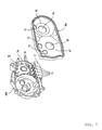
- FIG. 7 is a perspective view of the second case block 20b and the inner case 36a.
- a front half part 66 of the inner case 36a is formed into a bowl shape swelling out leftward.
- a rear half part of the inner case 36a is formed into a bowl shape swelling out rightward.
- a hole 68 for inserting the primary sheave shaft 23a (see FIG. 5 ) of the CVT 17 is formed on the front half part 66.
- a hole 69 for inserting the secondary sheave shaft 53 (see FIG. 5 ) of the CVT 17 is formed on the rear half part 66.
- the clutch cover 37 (see FIG. 5 ) interposed between the inner case 36a and the second case block 20b is not shown.
- Ventilation ports 72 are provided on the inner case 36a.
- the ventilation port is formed into a circular shape. Three ventilation ports are formed in positions upper than a vertical center of the inner case 36a. However, a shape of the ventilation port is not limited at all. A position of the ventilation port is not necessarily limited to an upper part of the inner case 36a.
- the ventilation port 72 is provided on each of the front half part 66 and the rear half part 67 of the inner case 36a. However, the ventilation port 72 can be formed on only either one of the front half part 66 and the rear half part 67. A number of the ventilation port 72 is not specifically limited either.
- a plurality of ventilation ports 73 are formed at a lower right part of the second case block 20b.
- the second case block 20b includes a periphery part 74 installed upright rightward.
- This periphery part 74 has a shape corresponding to an outline shape of the transmission casing 36.
- a lower part of the periphery part 74 has a notched part, in which the notches are formed as slits. Namely, it is formed into a so-called comb shape. Therefore, a space 75 divided demarcated by the second case block 20b and the inner case 36a is communicatively connected to an outside of the engine unit 15 (see FIG. 5 ) through the ventilation ports 75.
- the space 75 is formed between the clutch cover 37 and the inner case 36a in the rear half part of the second case block 20b (see FIG. 5 ).
- Reinforcement ribs 76 are provided on the comb-shaped part of the periphery part 74.
- An oil pan 77 is provided below the ventilation ports 73.
- a lower part of the periphery part 74 of the second case block 20b is formed into a comb shape.
- This comb-shaped part forms a plurality of slit-like ventilation ports 73.
- a shape of the ventilation port 73 is not limited to a slit, but of course can be an opening shaped differently, such as a circular shape.
- a shape, a size, or a number of the ventilation port 73 of the second case block 20b is not specifically limited.
- FIG. 8 is an enlarged drawing for showing a part of FIG. 5 .
- a sealing recess 61 is formed on the left side of the periphery part of the inner case 36a.
- a right periphery part of the second case block 20b is fitted in the sealing recess 61.
- An O-ring 62 is inserted in a space between the inner case 36a and the second case clock 20b in the sealing recess 61.
- a sealing recess 63 is formed on the right side of the periphery part of the inner case 36a.
- the periphery part of the outer case 36b is fitted in the sealing recess 63.
- An O-ring 64 is inserted in a space between the inner case 36a and the outer case 36b in the sealing recess 63.
- the outer case 36b and the second case block 20b are fastened together by a bolt 65 with the inner case 36a interposed between them.
- the centrifugal clutch 18 is mounted on the left side of the secondary sheave shaft 53.
- the centrifugal clutch 18 is a wet type multiple disc type clutch, and includes a generally cylindrical clutch housing 81 and a clutch boss 82.
- the clutch housing 81 is spline-fitted in the secondary sheave shaft 53, and rotates integrally with the secondary sheave shaft 53.
- a plurality of ring-shaped clutch plates 83 is mounted in the clutch housing 81. Those clutch plates 83 are arranged in the axial direction of the secondary sheave shaft 53 at intervals.
- a cylindrical gear 85 is rotatably fitted around a left part of the secondary sheave shaft 53 via a bearing 84.
- the clutch boss 82 is disposed inside in the redial direction of the clutch plate 83 and outside in the redial direction of the gear 85, and engages with the gear 85. Therefore, the gear 85 rotates together with the clutch boss 82.
- a plurality of ring-shaped friction plates 86 is mounted outside in the redial direction of the clutch boss 82. Those friction plates 86 are arranged in the axial direction of the secondary sheave shaft 53 at intervals. Each of the friction plates 86 is disposed between the neighboring clutch plates 83, 83.
- a plurality of cam surfaces 87 is formed on the left side of the clutch housing 81.
- a roller weight 88 is disposed between the cam surfaces 87 and the rightmost clutch plate 83 facing the cam surfaces 87.
- a state of the clutch is automatically switched between a clutch-in state (an engaging) and a clutch-off state (a disengaging) corresponding to the amount of centrifugal force acting on the roller weight 88.
- the roller weight 88 receives a centrifugal force and moves outside in the radial direction.
- the roller weight 88 pushes the clutch plates 83 leftward.
- the clutch plates 83 is compressedly contacted with the friction plates 86.
- a driving force of the secondary sheave shaft 53 is transmitted through the centrifugal clutch 18 to an output shaft (not shown) . It is a clutch-in state.
- the speed reduction mechanism 19 is interposed between the centrifugal clutch 18 and the output shaft (not shown).
- the speed reduction mechanism 19 has a speed changing shaft 89 disposed parallel to the secondary sheave shaft 53.
- the speed changing shaft 89 is rotatably supported by the first case block 20a via a bearing 90.
- the speed changing shaft 89 is rotatably supported by the second case block 20b via a bearing 91.
- a first speed changing gear 92 for engaging with the gear 85 is provided at a right end of the speed changing gear 89.
- a second speed changing gear 93 with a diameter smaller than the first speed changing gear 92 is provided at a center part of the speed changing shaft 89.
- the second speed changing gear 93 is disposed to engage with an output shaft not shown or a gear provided on the output shaft, which is not shown.
- the clutch boss 82 and the output shaft are coupled via the gear 85, the first speed changing gear 92, the speed changing shaft 89, the second speed changing gear 93, and so forth. Therefore, the output shaft rotates following a rotation of the clutch boss 82.
- a drive transmission mechanism such as a chain for transmitting a drive of the output shaft to the rear wheel 13 (see FIG. 1 ) is wound around the output shaft.
- a drive conversion mechanism can be a member other than a chain, such as a transmission belt, a gear mechanism combining a plurality of gears, and a drive shaft.
- the primary sheave shaft 23a of the CVT 17 rotates, and the impellers 60 of the fixed sheave half body 51a of the primary sheave 51 rotate together with it. As a result, a suction force inducting air from the intake duct 71 into the belt chamber 38 is generated.
- air is inducted into the air chamber 94 through the intake opening 94a (see FIG. 4 ).
- the air passes through the filter (not shown) and is cleaned up, and then the air is inducted into the belt chamber 38 through the intake duct 71.
- the air inducted into the belt chamber 38 flows through spaces around the primary sheave 51, the secondary sheave 52, and the V-belt 55, and cools down the primary sheave 51, the secondary sheave 52, and the V-belt 55.
- the air cooled down the primary sheave 51, the secondary sheave 52, and the V-belt is discharged from the belt chamber 38 through ventilation ports 72 of the inner case 36a.
- the air flows into the space 75 between the inner case 36a and the second case block 20b (see FIG. 7 ).
- the air in the space 75 is discharged outside through the ventilation ports 73 formed at the lower part of the second case block 20b.
- the intake duct 71 forming a part of the intake passage extends rearward from the transmission casing 36 passing over the seat pillar 6R in a side view. Therefore, the intake passage is elongated in the motorcycle 1. Meanwhile, the elongated intake passage may interrupt with the vehicle body frame 2.
- the intake duct 71 has the curving part 71a curving at a part around the seat pillar 6R. The intake duct 71 curves keeping clear of the seat pillar 6R. Therefore, an interruption between the intake duct 71 and the seat pillar 6R is prevented.
- a major factor of noise occurring in the CVT 17 is pitch noise due to a large number of the resin blocks 55a included in the V-belt 55.
- Pitch noise is a high frequency sound, and highly tends to travel linearly. Therefore, pitch noise is largely attenuated at the curving part 71a of the intake duct 71 when the pitch noise passes through the intake duct 71. Accordingly, noise of the CVT 17 released outside is sufficiently prevented because of a synergetic effect between a large length of the intake duct 71 and inclusion of the curving part 71a.
- an air passage should not have a curving part in the view of ventilation such as smooth introduction or discharge of air.
- the curving part 71a is provided in the intake duct 71 on purpose, and thereby it prevents high frequency sounds, which have a high tendency to travel straight, from leaking outside.
- the intake opening 78 to which the intake duct 71 is connected is formed at the front half part of the transmission casing 36 (above the primary sheave 51). Therefore, the intake duct 71 is connected to a part more forward than the rear end of the primary sheave 51. Thereby, a length of the intake duct 71 extending rearward can be larger. Therefore, noise of the CVT 17 can be more effectively prevented with the motorcycle 1.
- a pair of the right and left seat pillars 6R and 6L are provided in the motorcycle 1.
- a part of the engine unit 15 is supported by both the seat pillars 6R and 6L. Therefore, a rigidity of the vehicle body frame 2 can be enhanced.
- the seat pillars 6L and 6R are provided on the right and on the left as a pair, the seat pillars 6L and 6R protrude in the vehicle width direction.
- the intake duct 71 passes through a space between the left seat pillar 6L and the right seat pillar 6R. Thereby, noise of the CVT 17 can be prevented, and also the motorcycle 1 can be intended to be slimly formed.
- the right and left foot rests 80 are disposed outside of the respective seat pillars 6L and 6R in the vehicle width direction.
- the intake duct 71 passes through a space between the seat pillars 6L and 6R. Therefore, although the intake duct 71 extends rearward passing over the seat pillar 6R, the intake duct 71 does not disturb the feet of a rider on the foot rests 80.
- the intake duct 71 extends more rearward than the seat pillar 6R, and thus it facilitates a prevention of intrusion of muddy water and the like splashed up by the front wheel 12 into the intake duct 71.
- the intake opening 94a of the air chamber 94 of the motorcycle 1 is positioned upper than the pivot shaft 10. Therefore, the intake opening 94a is positioned relatively away from the ground, and disposed in a position such that the intake opening 94a is not apt to induct water and dust.
- the intake opening 94a is positioned below the seat 3. A part above the intake opening 94a is covered by the seat 3 because of such a disposition. Thus, intrusion of water, dust and so forth into the air chamber 94 can be prevented. Therefore, the motorcycle 1 facilitates supply of fresh air into the belt chamber 38.
- the intake duct 71 of the motorcycle 1 passes through a space between the cylinder 21 of the engine 16 and the seat pillar 6R. Also, the intake duct 71 passes through a space between the left seat pillar 6L and the right seat pillar 6R. Further, the intake duct 71 passes through a space between the rear cushion unit 30 and the seat pillar 6R. Therefore, a space between the seat pillar 6L and the seat pillar 6R, a space between the cylinder 21 and the seat pillar 6R, and a space between the rear cushion unit 30 and the seat pillar 6R can be effectively used as spaces for providing the air passage. Accordingly, the motorcycle 1 can certainly provide a sufficient space for disposing the air passage without making the vehicle larger. As a result, it can realize an air passage having a sufficient cross sectional area of a flow passage.
- the curving part 71a of the intake duct 71 is positioned inside the inner end of the seat pillar 6R in the vehicle width direction, that is, positioned left of the sear pillar 6R. Meanwhile, a part of the intake duct 71 (a part in a vicinity of the connection part where the intake duct 71 connects to the transmission casing 36) is positioned outside the seat pillar 6R in the vehicle width direction, that is, positioned right of the seat pillar 6R. In other words, the intake duct 71 reaches a part inside the seat pillar 6R from the part outside the seat pillar 6R in the vehicle width direction. The intake duct 71 largely curves. Therefore, a high frequency sound occurring in the CVT 17 can be more effectively prevented with the motorcycle 1 of this embodiment.
- an end (a right end) of the primary sheave shaft 23a is positioned inside an end (a right end) of the secondary sheave shaft 53 in the vehicle width direction.
- the primary sheave 51 has a more space on a lateral side of its sheave shaft comparing with a space that the secondary sheave 52 has.
- the intake duct 71 is connected to a part of the transmission casing 36 closer to the primary sheave 51. That is, the intake duct 71 is connected to the part that has more space on its lateral side. Therefore, as shown in FIG. 4 , such a connection can prevent a projection of the connection part between the intake duct 71 and the transmission casing 36 in a transverse direction, and thereby the motorcycle 1 can be facilitated to be slimmed down.
- the exhaust pipe 41 of the engine 16 extends rearward passing through a space below the intake duct 71 and the transmission casing 36 of the CVT 17.
- an interruption between the exhaust pipe 41 and the intake duct 71 can be facilely prevented. Therefore, the intake duct 71 can curve without being interrupted by the exhaust pipe 41, and a sufficient length of the intake duct 71 can be assured.
- the exhaust pipe 41 of the engine 16 extends forward and obliquely rightward downward, then curves rearward, passes through a space below the transmission casing 36 of the engine unit 15, and further extends rearward.
- a length of the air chamber 94 in the vertical direction is shortened to secure a space above the intake duct 71 and the air chamber 94, and thereby the exhaust pipe 41 passes through the space.
- the exhaust pipe 41 extends forward and obliquely rightward downward from the cylinder head 22, then curves rearward upward, passes through the space above the intake duct 71 and the air chamber 94, and further extends rearward.
- the muffler 42 is connected to a rear end of the exhaust pipe 41 similarly to the first embodiment.
- the muffler 42 is disposed on the right side above the rear wheel 13. Other parts of construction are almost the same as the first embodiment.
- the exhaust pipe 41 can be disposed above the intake duct 71 and the air chamber 94. Thereby, a sufficiently large space can be obtained below the frame 2.
- the transmission casing 36 to which the front part of the intake duct 71 is connected, and the air chamber 94 forming the rear part of the air passage are disposed on the same side (the right side) in the vehicle width direction.
- the transmission casing 36 is disposed on the right side in the vehicle width direction
- the air chamber 94 is disposed on the opposite side, which is the left side, in the vehicle width direction.
- the air chamber 94 and the air chamber 43 are disposed on the same side (the left side) in the vehicle width direction.
- the air chamber 94 and the air chamber 43 are formed into a united case body. Specifically, two spaces are formed inside a case body. That is, a case body is demarcated into a space for the air chamber 94 and a space for the air chamber 43.
- the rear end of the intake duct 71 is disposed on the left side in the vehicle width direction. Thereby, it makes a space on the opposite side, which is the right side. To effectively use this space, the battery 50 is disposed on the right side.
- the exhaust pipe 41 of the engine 16 is disposed on the right side in the vehicle width direction and above the transmission casing 36 similarly to the second embodiment. Other parts of construction are almost the same as the first embodiment.
- the intake duct 71 extends from the right side to the left side in the vehicle width direction, and thereby the intake duct 71 can be made longer.
- the air chamber 94 and the air chamber 43 are formed into a united case body and are made more compact. This assures an obtainment of a large space above the transmission casing 36.
- the intake duct 71 can be largely curved. Therefore, with this embodiment, noise of the CVT 17 can be more effectively prevented.
- the exhaust pipe 41 can be disposed in a space above the transmission casing 36, and thereby a sufficiently large space can be provided below the frame 2.
- the exhaust pipe 41 and the muffler 42 disposed above the transmission casing 36 in the third embodiment are disposed below the transmission casing 36, similarly to the first embodiment.
- the air passage for inducting air into the belt chamber 38 can be formed long, and noise can be prevented, similarly to all the embodiments described above.
- an interruption between the intake duct 71 and the exhaust pipe 41 and an interruption between the intake pipe 40 and the exhaust pipe 41 can be facilely prevented.
- the air chamber 94 to which the rear end of the intake duct 71 is connected is disposed on the left side in the vehicle width direction, which is the side opposite to the transmission casing 36.
- the air chamber 43 of the engine 16 is disposed on the right side in the vehicle width direction, which is the side opposite to the air chamber 94.
- Other parts of construction are the same as the first embodiment.
- the intake duct 71 extends from the right side to the left side in the vehicle width direction, and thus the intake duct 71 can be made long. Also, the intake duct 71 can be largely curved. Therefore, with this embodiment, noise of the CVT 17 can be effectively prevented also.
- the air chamber 43 is disposed on the side opposite to the air chamber 94 in the vehicle width direction, and thereby those parts can be laid out in a good balance. Therefore, with this embodiment, the air passage can be formed long without increasing a width of the vehicle. An interruption between the intake duct 71, the intake pipe 40 and the exhaust pipe 41 can be facilely prevented with this embodiment also.
- the exhaust pipe 41 of the engine 16 extends forward and obliquely rightward downward from the cylinder head 22, then curves rearward, passes through a space below the transmission casing 36 of the engine unit 15, and further extends rearward.
- a vertical length of the air chamber 94 is shortened to assure a space above the air chamber 94. Thereby, the exhaust duct 41 passes through the space.
- the exhaust pipe 41 extends forward and obliquely leftward downward from the cylinder head 22, then curves rearward, passes through a space inside the seat pillar 6L and a space above the air chamber 94, and further extends rearward.
- the muffler 42 is connected to the rear end of the exhaust pipe 41.
- the muffler 42 is disposed on the left side above the rear wheel 13. Other parts of construction are almost the same as the fifth embodiment.
- the exhaust pipe 41 is disposed above the air chamber 94, and thereby a sufficiently large space can be obtained below the frame 2.
- the air chamber 43 is disposed on the same side as the air chamber 94 (the right side) in the vehicle width direction, and the air chamber 43 and the air chamber 94 are formed into a united case body. Also, in this embodiment, the air chamber 43 is disposed on the right side in the vehicle width direction, and thereby a space is obtained on the left side. The battery 50 is disposed in this obtained space on the left side. Other parts of construction are almost the same as the first embodiment.
- the exhaust pipe 41 and the muffler 42 disposed below the transmission casing 36 in the seventh embodiment are disposed above the battery 50.
- the air passage for inducting air into the belt chamber 38 can be formed long. Noise of the CVT 17 can be effectively prevented with this embodiment also.
- the air passage is the intake passage for inducting air into the belt chamber 38, and this intake passage is constructed with the intake duct 71 and the air chamber 94.
- the air passage of an embodiment of the present invention is not limited to the above intake passage.
- the air passage of an embodiment of the present invention can be also an exhaust passage for discharging air from the belt chamber 38.
- the air passage of an embodiment of the present invention can be, for example, an exhaust passage including a duct 71 used as an exhaust duct, in which the duct 71 used as an intake duct in the above embodiments is used as the exhaust duct for discharging a cooling air inducted into the belt chamber 38.
- a duct for an intake purpose or an intake opening can be separately provided for the transmission casing 36, for example.
- the present invention is valuable for a motorcycle including a belt type continuously variable transmission having a resin block belt.
Landscapes
- Engineering & Computer Science (AREA)
- General Engineering & Computer Science (AREA)
- Mechanical Engineering (AREA)
- Chemical & Material Sciences (AREA)
- Combustion & Propulsion (AREA)
- Transportation (AREA)
- General Details Of Gearings (AREA)
- Transmissions By Endless Flexible Members (AREA)
- Cosmetics (AREA)
- Handcart (AREA)
- Compositions Of Macromolecular Compounds (AREA)
Abstract
Description
- The present invention relates to a motorcycle including a belt type continuously variable transmission having a resin block belt.
- Conventionally, a motorcycle including a belt type continuously variable transmission is known in the art (for example, see
JP-A-2002-147582 - A belt type continuously variable transmission includes a primary sheave, a secondary sheave, and a V-belt wound around the primary sheave and the secondary sheave. A driving force of a crankshaft of an engine is transmitted in order of the primary sheave, the V-belt, and the secondary sheave. The driving force is transmitted to a driving wheel after a speed is changed. The primary sheave, the V-belt, and the secondary sheave are housed inside the transmission casing. That is, a belt chamber is formed inside the transmission casing, and the primary sheave, the V-belt, and the secondary sheave are housed in the belt chamber.
- In the motorcycle disclosed in
JP-A-2002-147582 - In consideration of the problem,
JP-A-2002-147582 - However, the V-belt runs at a high speed, and the primary sheave and the secondary sheave rotate at high speeds. Therefore, it is necessary to dispose the sound absorption material not to contact with the V-belt and both the sheaves. In other words, it is necessary to dispose the sound absorption material mentioned above at a position with a certain distance away from the V-belt and both the sheaves. Therefore, if the sound absorption material is disposed on the inner surface of the transmission casing as in the motorcycle disclosed in
JP-A-2002-147582 JP-A-2002-147582 - Normally, a sound absorption material also has a thermal insulation function. Therefore, a temperature inside the belt chamber is apt to rise in the motorcycle disclosed in
JP-A-2002-147582 - The present invention is made in consideration of the foregoing problems and seeks to provide a noise preventing means suitable for a motorcycle including a belt type continuously variable transmission having a resin block belt.
- An aspect of the present invention provides a motorcycle, including: an engine unit having a transmission casing in which a belt chamber is formed, and a belt type continuously variable transmission housed in the belt chamber and having a resin block belt; a frame member disposed more rearward than or above the transmission casing, extending in a vertical direction or an obliquely upward and downward directions, and supporting at least a part of the engine unit; and an air passage connected to the transmission casing, and constructed with an intake passage for inducting air into the belt chamber or an exhaust passage for discharging air from the belt chamber, in which the air passage extends rearward from the transmission casing passing over the frame member in a side view, and has a curving part curving at a part around the frame member.
- The inventors determined that the noise produced in a belt type continuously variable transmission having a resin block belt is mostly pitch noise caused due to motions of a plurality of resin blocks running one after another, and the pitch noise is a so-called high frequency sound. They noticed that high frequency sound generally has characteristics of high linearity and weak transmission. The claimed invention employs a relationship between an air passage for cooling a belt chamber and a reduction of high frequency sounds.
- In an embodiment of the invention, the air passage of the motorcycle extends rearward from the transmission casing passing over the frame member, and is a long air passage. Therefore, noise of the belt type continuously variable transmission occurred in the belt chamber is damped inside the air passage before it reaches outside. Consequently, noise released outside from the air passage is reduced to a relatively low level. The air passage has the curving part curving at a part around the frame member. Thereby, an interruption between the air passage and the frame member can be prevented, and a linear travel of a high frequency sound, which has a high tendency to travel linearly, can be prevented. Accordingly, the motorcycle can effectively prevent high frequency sound that is considered to be a major cause of noise. Therefore, the motorcycle can effectively prevent noise caused by the resin block belt.
- An embodiment of the present invention can provide a noise preventing means suitable for the motorcycle including a belt type continuously variable transmission having a resin block belt.
- Embodiments of the present invention will be described hereinafter, by way of example only, with reference to the drawings.
-
FIG. 1 is a side view of a motorcycle according to a first embodiment. -
FIG. 2 is a perspective view viewing a vehicle body frame from the left front. -
FIG. 3 is a right side view showing a part of the motorcycle according to the first embodiment. -
FIG. 4 is a plan view showing a part of the motorcycle according to the first embodiment. -
FIG. 5 is a cross sectional view of an engine unit. -
FIG. 6(a) is a cross sectional view of a resin block belt, and (b) is a side view of the resin block belt. -
FIG. 7 is a perspective view of a second case block and an inner case. -
FIG. 8 is an enlarged cross sectional view showing a vicinity of a centrifugal clutch inFIG. 5 . -
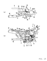
FIGs. 9a and 9b show a part of the motorcycle according to a second embodiment, in whichFIG. 9a is a plan view, andFIG. 9b is a right side view. -
FIGs. 10a and 10b show a part of the motorcycle according to a third embodiment, in whichFIG. 10a is a plan view, andFIG. 10b is a right side view. -
FIGs. 11a and 11b show a part of the motorcycle according to a fourth embodiment, in whichFig. 11a is a plan view, andFIG. 11b is a right side view. -
FIGs. 12a and 12b show a part of the motorcycle according to a fifth embodiment, in whichFIG. 12a is a plan view, andFIG. 12b is a right side view. -
FIGs. 13a and 13b show a part of the motorcycle according to a sixth embodiment, in whichFIG. 13a is a plan view, andFIG. 13b is a right side view. -
FIGs. 14a and 14b show a part of the motorcycle according to a seventh embodiment, in whichFIG. 14a is a plan view, andFIG. 14b is a right side view. -
FIGs. 15a and 15b show a part of the motorcycle according to an eighth embodiment, in whichFIG. 15a is a plan view, andFIG. 15b is a right side view. - Example embodiments of the present invention will be described hereinafter in detail with reference to the drawings.
- As shown in
FIG.1 , a straddle type vehicle according to this embodiment is a motorcycle 1. The motorcycle 1 includes avehicle body frame 2 for composing a skeletal structure, and aseat 3 on which a rider (or driver) sits. The motorcycle 1 is a so-called off-road type motorcycle. However, a motorcycle according to the present invention is not limited to this, but can be a motorcycle other than an off-road type (such as on-road type, scooter type, or so-called moped type motorcycle). In addition, the directions of front and rear, and right and left, are the directions in the view of a rider sitting on theseat 3 in the following descriptions. -
FIG. 2 is a perspective view viewing thevehicle body frame 2 from the left front. As shown inFIG. 2 , thevehicle body frame 2 includes a head pipe 4, adown tube 5 extending downward from the head pipe 4, and amain tube 6 extending rearward from the head pipe 4 above thedown tube 5. Themain tube 6 extends rearward from the head pipe 4. A midway part of themain tube 6 bifurcates into aleft seat pillar 6L extending leftward and aright seat pillar 6R extending rightward. Theseseat pillars seat pillars - Seat rails 7L and 7R are connected to vicinities of the curving parts of the
respective seat pillars buckstays 8L and 8R are connected to therespective seat rails buckstays 8L and 8R are connected to bottom ends of therespective seat pillars pivot part 6a into which apivot shaft 10 mentioned below is inserted is provided at a bottom end of each of theseat pillars rear arm 9 described below is coupled to thepivot part 6a. - The
rear arm 9 includes a generallyU-shaped arm part 9a formed to open rearward, and a generally U-shaped coupling part 9b formed to open forward. Apipe 9c is provided on an end of each of right and left branches of the coupling part 9b. Thepivot shaft 10 mentioned above passes through the right and leftpivot parts 6a and the right and leftpipes 9c. Thereby, therear arm 9 is swingably coupled to the bottom ends of theseat pillars pivot shaft 10. In this embodiment, thepivot shaft 10 is formed with a long bolt, and a left end of thepivot shaft 10 is fixed by anut 10a. - A front fork 11 (see
FIG. 1 ) is inserted into the head pipe 4. As shown inFIG. 1 , afront wheel 12 is supported by the front fork 11. Arear wheel 13 is supported by a bottom part of thearm part 9a of therear arm 9. Also, a cover 14 for covering thevehicle body frame 2 is disposed above thevehicle body frame 2. Theseat 3 mentioned above is disposed slightly more rearward than a center of the cover 14. -
FIG. 3 is a right side view showing a part ofFIG. 1 (a construction of each part around the vehicle body frame 2). As shown inFIG. 3 , anengine unit 15 for driving the rear wheel 13 (seeFIG. 1 ) is suspended on thevehicle body frame 2. Specifically, theengine unit 15 is disposed among thedown tube 5 and theseat pillars down tube 5 and each of theseat pillars engine unit 15 includes anengine 16 and a belt type continuously variable transmission 17 (hereinafter referred to as CVT 17) (seeFIG. 5 ). This part will be described in detail below. Theengine 16 includes acrankcase 20, acylinder 21, and acylinder head 22. TheCVT 17 is housed in atransmission casing 36 connected to thecrankcase 20. -
FIG. 4 is a plan view showing a layout around theseat pillars FIG. 4 ,rear cushion unit 30 is provided at a center in the vehicle width direction. As shown inFIG. 3 , therear cushion unit 30 is provided in a manner such that it is positioned between themain tube 6 and therear arm 9 and couples themain tube 6 and therear arm 9 together. The motorcycle 1 of this embodiment includes only onerear cushion unit 30, and has a so-called mono suspension construction. In addition, therear cushion unit 30 is not limited to a rear cushion unit directly coupled to therear arm 9, but can be a rear cushion unit coupled to therear arm 9 via a link. - An end of an
intake duct 71 for inducting cooling air into a belt chamber 38 (seeFIG. 5 ) in thetransmission casing 36 is connected to a front half part of thetransmission casing 36. In a right side view as shown inFIG. 3 , theintake duct 71 extends upward from thetransmission casing 36, then curves, and extends rearward passing over theseat pillar 6R. Anair chamber 94 is connected to a rear end of theintake duct 71. An air filter (not shown) is disposed inside theair chamber 94. The whole of theintake duct 71 and theair chamber 94 forms an example of an air passage. - As shown in
FIG. 4 , theintake duct 71 extends rearward passing through a space between theleft seat pillar 6L and theright seat pillar 6R. Also, theintake duct 71 passes through a space between thecylinder 21 of theengine 16 and theseat pillar 6R, and a space between therear cushion unit 30 and theseat pillar 6R. Theintake duct 71 has acurving part 71a curving at a part around theseat pillar 6R. - In the plan view shown in
FIG. 4 , foot rests 80 as foot supporting members for supporting the feet of a rider are provided outside theseat pillars curving part 71a mentioned above is positioned at a part inside an inner end of theseat pillar 6R in the vehicles width direction, that is, positioned on the left of theseat pillar 6R. Thereby, theintake duct 71 passes through a space inside thefoot rest 80. Meanwhile, a part of the intake duct 71 (a part in a vicinity of a connection part where theintake duct 71 connects to the transmission casing 36) is positioned outside theseat pillar 6R in the vehicle width direction, that is, positioned on the right of theseat pillar 6R. - An
intake opening 94a for inducting fresh air into theair chamber 94 is provided on an inner end surface (a left side surface) of theair chamber 94 in the vehicle width direction. Theintake opening 94a is positioned below the seat 3 (seeFIG. 1 ). As shown inFIG. 3 , theintake opening 94a is positioned above thepivot shaft 10. Further, theintake opening 94a of theair chamber 94 forms an example of an intake opening of the air passage. - An end of an
intake pipe 40 for supplying air to theengine 16 is connected to a rear side of thecylinder head 22 of theengine 16. Theintake pipe 40 passes through a space between theseat pillar 6L and theseat pillar 6R (seeFIG. 4 ), and extends leftward and rearward. Anair chamber 43 is connected to a rear end of theintake pipe 40. Anintake opening 43a for inducting fresh air into theair chamber 43 is provided on an inner end surface (a right side surface) of theair chamber 43 in the vehicle width direction. Theintake opening 43a is positioned below the seat 3 (seeFIG. 1 ). - Meanwhile, as shown in
FIG.3 , anexhaust pipe 41 is connected to a front side of thecylinder head 22. Theexhaust pipe 41 extends forward and obliquely rightward and downward from thecylinder head 22, then curves rearward, passes through a space below thetransmission casing 36 of theengine unit 15, and further extends rearward. Amuffler 42 is connected to a rear end of theexhaust pipe 41. Themuffler 42 is disposed on the right of the rear wheel 13 (seeFIG. 1 ). - As shown in
FIG. 4 , abattery 50 is provided in the rear of therear cushion unit 30 and between theair chamber 43 and theair chamber 94. Thebattery 50 is disposed below the seat 3 (seeFIG. 1 ). -
FIG. 5 shows a cross section of theengine unit 15. As shown inFIG. 5 , theengine unit 15 includes theengine 16, theCVT 17, a centrifugal clutch 18, and aspeed reduction mechanism 19. Here, theengine 16 is a four cycle single cylinder engine. However, theengine 16 in an example embodiment of the present invention can be a two cycle engine for example, or a multi-cylinder engine. - The
engine 16 includes thecrankcase 20, thecylinder 21 connected to thecrankcase 20, and thecylinder head 22 connected to thecylinder 21. Thecrankcase 20 has two separate case blocks, that is, afirst case block 20a positioned on the left and asecond case block 20b positioned on the right. Thefirst case block 20a and thesecond case block 20b are facing each other in the vehicle width direction. - A
crankshaft 23 is housed in thecrankcase 20. Thecrankshaft 23 extends in the vehicle width direction and is disposed horizontally. Thecrankshaft 23 is supported by thefirst case block 20a via abearing 24a, and supported by thesecond case block 20b via abearing 24b. - A
piston 25 is slidably inserted into thecylinder 21. An end of a connectingrod 26 is connected to thepiston 25. Acrankpin 28 is provided between aleft crank arm 27a and aright crank arm 27b of thecrankshaft 23. The other end of the connectingrod 26 is coupled to thecrankpin 28. - A
concaving part 22a, and an intake port and an exhaust port communicatively connected to theconcaving part 22a, that are not shown, are formed in thecylinder head 22. An ignition plug 29 is inserted into thecylinder head 22. Theintake pipe 40 mentioned above (seeFIGS. 1 and3 ) is connected to the intake port. Theexhaust pipe 41 mentioned above (seeFIGs. 1 and3 ) is connected to the exhaust port. - As shown in
FIG. 5 , a cam chain chamber 31 for connecting an inside of thecrankcase 20 and an inside of thecylinder head 22 together is formed at a left part inside thecylinder 21. Atiming chain 32 is disposed in the cam chain chamber 31. Thetiming chain 32 is wound around thecrankshaft 23 and acamshaft 33. Thecamshaft 33 rotates following a rotation of thecrankshaft 23, and opens or closes an intake valve or an exhaust valve, which are not shown. - A generator case 35 for accommodating a
generator 34 is mounted on the left side of a front half part of thefirst case block 20a. Thetransmission casing 36 for accommodating theCVT 17 is mounted on the right side of thesecond case block 20b. An opening is formed on the right side of a rear half part of thesecond case block 20b. This opening is blocked by aclutch cover 37. - The
transmission casing 36 is formed independently from thecrankcase 20, and is constructed with aninner case 36a for covering an inner part (a left part) of the CVT in the vehicle width direction and anouter case 36b for covering an outer part (a right part) of theCVT 17 in the vehicle width direction. Theinner case 36a is mounted on the right side of thecrankcase 20. Theouter case 36b is mounted on the right side of theinner case 36a. A belt chamber 38 for accommodating theCVT 17 is formed in a space formed between theinner case 36a and theouter case 36b. Anintake opening 78 is formed on a top surface of theouter case 36b. Theintake duct 71 mentioned above (seeFIGs. 1 and3 ) is connected to theintake opening 78. - A right end of the
crankshaft 23 passes through thesecond case block 20b and theinner case 36a, and extends to the belt chamber 38. Aprimary sheave 51 of theCVT 17 is fitted in the right end of thecrankshaft 23. Therefore, theprimary sheave 51 rotates following a rotation of thecrankshaft 23. This right part of the crankshaft 23 (strictly, a part more rightward than the bearing 24b) forms aprimary sheave shaft 23a. - Meanwhile, a left end of the
crankshaft 23 passes through thefirst case block 20a, and extends into the generator case 35. Thegenerator 34 is mounted at this left end of thecrankshaft 23. Thegenerator 34 includes astator 34a and arotor 34b facing thestator 34a. Therotor 34b is fixed to a sleeve 39 rotating together with thecrankshaft 23. Thestator 34a is fixed to the generator case 35. - A
secondary sheave shaft 53 in which asecondary sheave 52 is fitted is disposed parallel to thecrankshaft 23 in a rear half part in thecrankcase 20. A right part of a center part of thesecondary sheave shaft 53 is supported by theclutch cover 37 via abearing 54a. A left part of thesecondary sheave shaft 53 is supported by a left end of thesecond case block 20b via abearing 54b. Thesecondary sheave 52 is coupled to a right end of thesecondary sheave shaft 53. - The
CVT 17 includes theprimary sheave 51, thesecondary sheave 52, and a V-belt 55 wound around theprimary sheave 51 and thesecondary sheave 52. As mentioned above, theprimary sheave 51 is mounted on the right side of thecrankshaft 23. Thesecondary sheave 52 is coupled to a right part of thesecondary sheave shaft 53. - The
primary sheave 51 includes a fixedsheave half body 51a positioned outside in the vehicle width direction, a movablesheave half body 51b positioned inside in the vehicle width direction and facing the fixedsheave half body 51a. The fixedsheave half body 51a is fixed to a right part of theprimary sheave shaft 23a, and rotates together with theprimary sheave 23a. The movablesheave half body 51b is disposed on the left side of the fixedsheave half body 51a, and slidably mounted on theprimary sheave shaft 23a. Therefore, the movablesheave half body 51b rotates together with theprimary sheave 23a, and is slidable in the axis direction of theprimary sheave shaft 23a. Abelt groove 51c is formed between the fixedsheave half body 51a and the movablesheave half body 51b. A cam surface 56 is formed on the left side of the movablesheave half body 51b. Acam plate 57 is disposed on the left side of the cam surface 56. A roller weight 58 is disposed between the cam surface 56 of the movablesheave half body 51b and thecam plate 57. - The
secondary sheave 52 includes a fixedsheave half body 52a positioned inside in the vehicle width direction and a movablesheave half body 52b positioned outside in the vehicle width direction and facing the fixedsheave half body 52a. The movablesheave half body 52b is mounted on a right part of thesecondary sheave shaft 53. The movablesheave half body 52b rotates together with thesecondary sheave shaft 53, and is slidable in the axis direction of thesecondary sheave shaft 53. Acompression coil spring 59 is provided on the right side of thesecondary sheave 52. The movablesheave half body 52b receives a leftward pressure from thecompression coil spring 59. An axis part of the fixedsheave half body 52a is a cylindrical slide collar, and is spline-fitted into thesecondary sheave shaft 53. A V-shapedbelt groove 52c is formed between the fixedsheave half body 52a and the movablesheave half body 52b. - As shown in
FIG. 6 , the V-belt 55 includes a plurality ofresin blocks 55a formed into a shape such that a letter H is rotated by a right angle and a pair ofcoupling members 55b for coupling the plurality of the resin blocks 55a together. Thecoupling member 55b is fitted in aconcaving part 55c formed from a side surface of theresin block 55a toward a center part, and extends in a direction that theresin blocks 55a are arrayed as shown inFIG. 6(b) . As shown inFIG. 6(a) , a cross section of theresin block 55a is formed into a shape such that a letter H is rotated by a right angle. Theresin block 55a is also formed into a V-shape, and thereby it is formed to match the V-shapes of thebelt groove 51c of theprimary sheave 51 and thebelt groove 52c of the secondary sheave 52 (seeFIG. 5 ). - As shown in
FIG. 5 , a plurality ofimpellers 60 are formed at a right part of the fixedsheave half body 51a of theprimary sheave 51. Also, as mentioned above, the intake duct 71 (seeFIG. 1 ) is connected to theintake opening 78 formed on a top surface of thetransmission casing 36. Further, theintake opening 78 is formed on the front half part (above the primary sheave 51) of thetransmission casing 36. Therefore, theintake duct 71 is connected to a part more forward than a rear end of theprimary sheave 51. - With such a construction, when the fixed
sheave half body 51a rotates together with theprimary sheave shaft 23a, theimpellers 60 induct air into the belt chamber 38 through theintake opening 78, and also air inside the belt chamber 38 is discharged outside. In this embodiment, theimpellers 60 are formed to helically extend outside in the diameter direction from a center part of the fixedsheave half body 51a. However, a shape of theimpeller 60 is not limited to any specific shape, and a number of the impellers is not limited to a specific number either. In addition, impellers as a body separated from the fixedsheave half body 51a can be provided outside the fixedsheave half body 51a. -
FIG. 7 is a perspective view of thesecond case block 20b and theinner case 36a. As shown inFIG. 7 , a fronthalf part 66 of theinner case 36a is formed into a bowl shape swelling out leftward. A rear half part of theinner case 36a is formed into a bowl shape swelling out rightward. Ahole 68 for inserting theprimary sheave shaft 23a (seeFIG. 5 ) of theCVT 17 is formed on the fronthalf part 66. Ahole 69 for inserting the secondary sheave shaft 53 (seeFIG. 5 ) of theCVT 17 is formed on therear half part 66. InFIG. 7 , the clutch cover 37 (seeFIG. 5 ) interposed between theinner case 36a and thesecond case block 20b is not shown. -
Ventilation ports 72 are provided on theinner case 36a. In this embodiment, the ventilation port is formed into a circular shape. Three ventilation ports are formed in positions upper than a vertical center of theinner case 36a. However, a shape of the ventilation port is not limited at all. A position of the ventilation port is not necessarily limited to an upper part of theinner case 36a. In this embodiment, theventilation port 72 is provided on each of the fronthalf part 66 and therear half part 67 of theinner case 36a. However, theventilation port 72 can be formed on only either one of the fronthalf part 66 and therear half part 67. A number of theventilation port 72 is not specifically limited either. - A plurality of
ventilation ports 73 are formed at a lower right part of thesecond case block 20b. Specifically, thesecond case block 20b includes aperiphery part 74 installed upright rightward. Thisperiphery part 74 has a shape corresponding to an outline shape of thetransmission casing 36. Further, a lower part of theperiphery part 74 has a notched part, in which the notches are formed as slits. Namely, it is formed into a so-called comb shape. Therefore, aspace 75 divided demarcated by thesecond case block 20b and theinner case 36a is communicatively connected to an outside of the engine unit 15 (seeFIG. 5 ) through theventilation ports 75. In addition, because a right part of the rear half part of thesecond case block 20b is covered by theclutch cover 37, thespace 75 is formed between theclutch cover 37 and theinner case 36a in the rear half part of thesecond case block 20b (seeFIG. 5 ). -
Reinforcement ribs 76 are provided on the comb-shaped part of theperiphery part 74. Anoil pan 77 is provided below theventilation ports 73. - With the above construction, air in the belt chamber 38 is introduced into the
space 75 through theventilation ports 72 of theinner case 36a, and further discharged toward theoil pan 77 through theventilation ports 73 of thesecond case block 20b. As a result, the air is discharged outside theengine unit 15. - As foregoing, in this embodiment, a lower part of the
periphery part 74 of thesecond case block 20b is formed into a comb shape. This comb-shaped part forms a plurality of slit-like ventilation ports 73. However, a shape of theventilation port 73 is not limited to a slit, but of course can be an opening shaped differently, such as a circular shape. A shape, a size, or a number of theventilation port 73 of thesecond case block 20b is not specifically limited. -
FIG. 8 is an enlarged drawing for showing a part ofFIG. 5 . As shown inFIG. 8 , a sealingrecess 61 is formed on the left side of the periphery part of theinner case 36a. A right periphery part of thesecond case block 20b is fitted in the sealingrecess 61. An O-ring 62 is inserted in a space between theinner case 36a and thesecond case clock 20b in the sealingrecess 61. A sealingrecess 63 is formed on the right side of the periphery part of theinner case 36a. The periphery part of theouter case 36b is fitted in the sealingrecess 63. An O-ring 64 is inserted in a space between theinner case 36a and theouter case 36b in the sealingrecess 63. Theouter case 36b and thesecond case block 20b are fastened together by abolt 65 with theinner case 36a interposed between them. - The centrifugal clutch 18 is mounted on the left side of the
secondary sheave shaft 53. The centrifugal clutch 18 is a wet type multiple disc type clutch, and includes a generally cylindricalclutch housing 81 and aclutch boss 82. Theclutch housing 81 is spline-fitted in thesecondary sheave shaft 53, and rotates integrally with thesecondary sheave shaft 53. A plurality of ring-shapedclutch plates 83 is mounted in theclutch housing 81. Thoseclutch plates 83 are arranged in the axial direction of thesecondary sheave shaft 53 at intervals. - A
cylindrical gear 85 is rotatably fitted around a left part of thesecondary sheave shaft 53 via abearing 84. Theclutch boss 82 is disposed inside in the redial direction of theclutch plate 83 and outside in the redial direction of thegear 85, and engages with thegear 85. Therefore, thegear 85 rotates together with theclutch boss 82. A plurality of ring-shapedfriction plates 86 is mounted outside in the redial direction of theclutch boss 82. Thosefriction plates 86 are arranged in the axial direction of thesecondary sheave shaft 53 at intervals. Each of thefriction plates 86 is disposed between the neighboringclutch plates - A plurality of cam surfaces 87 is formed on the left side of the
clutch housing 81. Aroller weight 88 is disposed between the cam surfaces 87 and the rightmostclutch plate 83 facing the cam surfaces 87. - In the centrifugal clutch 18, a state of the clutch is automatically switched between a clutch-in state (an engaging) and a clutch-off state (a disengaging) corresponding to the amount of centrifugal force acting on the
roller weight 88. - That is, as a rotational speed of the
clutch housing 81 becomes a prescribed speed or more, theroller weight 88 receives a centrifugal force and moves outside in the radial direction. Theroller weight 88 pushes theclutch plates 83 leftward. As a result, theclutch plates 83 is compressedly contacted with thefriction plates 86. A driving force of thesecondary sheave shaft 53 is transmitted through the centrifugal clutch 18 to an output shaft (not shown) . It is a clutch-in state. - Meanwhile, as a rotational speed of the
clutch housing 81 becomes less than a prescribed speed, a centrifugal force acting on theroller weight 88 becomes small, and theroller weight 88 moves inside in the radial direction. As a result, theclutch plates 83 and thefriction plates 86 are released from the compressed contact. Now, a driving force of thesecondary sheave shaft 53 is not transmitted to the output shaft. It is a clutch-off state. In addition, the side lower than thesecondary sheave shaft 53 shows a clutch-in state, and the upper side shows a clutch-out state inFIG. 8 . - The
speed reduction mechanism 19 is interposed between the centrifugal clutch 18 and the output shaft (not shown). Thespeed reduction mechanism 19 has aspeed changing shaft 89 disposed parallel to thesecondary sheave shaft 53. Thespeed changing shaft 89 is rotatably supported by thefirst case block 20a via abearing 90. Also, thespeed changing shaft 89 is rotatably supported by thesecond case block 20b via abearing 91. A firstspeed changing gear 92 for engaging with thegear 85 is provided at a right end of thespeed changing gear 89. - A second
speed changing gear 93 with a diameter smaller than the firstspeed changing gear 92 is provided at a center part of thespeed changing shaft 89. The secondspeed changing gear 93 is disposed to engage with an output shaft not shown or a gear provided on the output shaft, which is not shown. - With such a construction, the
clutch boss 82 and the output shaft are coupled via thegear 85, the firstspeed changing gear 92, thespeed changing shaft 89, the secondspeed changing gear 93, and so forth. Therefore, the output shaft rotates following a rotation of theclutch boss 82. In addition, although not shown, a drive transmission mechanism such as a chain for transmitting a drive of the output shaft to the rear wheel 13 (seeFIG. 1 ) is wound around the output shaft. A drive conversion mechanism can be a member other than a chain, such as a transmission belt, a gear mechanism combining a plurality of gears, and a drive shaft. - The foregoing is the construction of the
engine unit 15. Next, a cooling operation of the CVT will be described. - When the
engine unit 15 operates, theprimary sheave shaft 23a of theCVT 17 rotates, and theimpellers 60 of the fixedsheave half body 51a of theprimary sheave 51 rotate together with it. As a result, a suction force inducting air from theintake duct 71 into the belt chamber 38 is generated. - Accordingly, air is inducted into the
air chamber 94 through theintake opening 94a (seeFIG. 4 ). The air passes through the filter (not shown) and is cleaned up, and then the air is inducted into the belt chamber 38 through theintake duct 71. The air inducted into the belt chamber 38 flows through spaces around theprimary sheave 51, thesecondary sheave 52, and the V-belt 55, and cools down theprimary sheave 51, thesecondary sheave 52, and the V-belt 55. - The air cooled down the
primary sheave 51, thesecondary sheave 52, and the V-belt is discharged from the belt chamber 38 throughventilation ports 72 of theinner case 36a. The air flows into thespace 75 between theinner case 36a and thesecond case block 20b (seeFIG. 7 ). The air in thespace 75 is discharged outside through theventilation ports 73 formed at the lower part of thesecond case block 20b. With the above air flow, theCVT 17 is continuously and regularly cooled down. - As foregoing, in the motorcycle 1 in this embodiment, the
intake duct 71 forming a part of the intake passage (air passage) extends rearward from thetransmission casing 36 passing over theseat pillar 6R in a side view. Therefore, the intake passage is elongated in the motorcycle 1. Meanwhile, the elongated intake passage may interrupt with thevehicle body frame 2. However, in this embodiment, theintake duct 71 has thecurving part 71a curving at a part around theseat pillar 6R. Theintake duct 71 curves keeping clear of theseat pillar 6R. Therefore, an interruption between theintake duct 71 and theseat pillar 6R is prevented. - With this embodiment, noise of the
CVT 17, which occurs inside the belt chamber 38, is damped largely while passing through theintake duct 71 because theintake duct 71 is long. Also, as mentioned above, a major factor of noise occurring in theCVT 17 is pitch noise due to a large number of theresin blocks 55a included in the V-belt 55. Pitch noise is a high frequency sound, and highly tends to travel linearly. Therefore, pitch noise is largely attenuated at thecurving part 71a of theintake duct 71 when the pitch noise passes through theintake duct 71. Accordingly, noise of theCVT 17 released outside is sufficiently prevented because of a synergetic effect between a large length of theintake duct 71 and inclusion of thecurving part 71a. - Generally, it is preferable that an air passage should not have a curving part in the view of ventilation such as smooth introduction or discharge of air. However, in this embodiment, the
curving part 71a is provided in theintake duct 71 on purpose, and thereby it prevents high frequency sounds, which have a high tendency to travel straight, from leaking outside. - As shown in
FIG. 5 , in this embodiment, theintake opening 78 to which theintake duct 71 is connected is formed at the front half part of the transmission casing 36 (above the primary sheave 51). Therefore, theintake duct 71 is connected to a part more forward than the rear end of theprimary sheave 51. Thereby, a length of theintake duct 71 extending rearward can be larger. Therefore, noise of theCVT 17 can be more effectively prevented with the motorcycle 1. - A pair of the right and left
seat pillars engine unit 15 is supported by both theseat pillars vehicle body frame 2 can be enhanced. On the other hand, because theseat pillars seat pillars intake duct 71 passes through a space between theleft seat pillar 6L and theright seat pillar 6R. Thereby, noise of theCVT 17 can be prevented, and also the motorcycle 1 can be intended to be slimly formed. - In the motorcycle 1, the right and left foot rests 80 are disposed outside of the
respective seat pillars intake duct 71 passes through a space between theseat pillars intake duct 71 extends rearward passing over theseat pillar 6R, theintake duct 71 does not disturb the feet of a rider on the foot rests 80. - Also, in this embodiment, the
intake duct 71 extends more rearward than theseat pillar 6R, and thus it facilitates a prevention of intrusion of muddy water and the like splashed up by thefront wheel 12 into theintake duct 71. - The
intake opening 94a of theair chamber 94 of the motorcycle 1 is positioned upper than thepivot shaft 10. Therefore, theintake opening 94a is positioned relatively away from the ground, and disposed in a position such that theintake opening 94a is not apt to induct water and dust. Theintake opening 94a is positioned below theseat 3. A part above theintake opening 94a is covered by theseat 3 because of such a disposition. Thus, intrusion of water, dust and so forth into theair chamber 94 can be prevented. Therefore, the motorcycle 1 facilitates supply of fresh air into the belt chamber 38. - The
intake duct 71 of the motorcycle 1 passes through a space between thecylinder 21 of theengine 16 and theseat pillar 6R. Also, theintake duct 71 passes through a space between theleft seat pillar 6L and theright seat pillar 6R. Further, theintake duct 71 passes through a space between therear cushion unit 30 and theseat pillar 6R. Therefore, a space between theseat pillar 6L and theseat pillar 6R, a space between thecylinder 21 and theseat pillar 6R, and a space between therear cushion unit 30 and theseat pillar 6R can be effectively used as spaces for providing the air passage. Accordingly, the motorcycle 1 can certainly provide a sufficient space for disposing the air passage without making the vehicle larger. As a result, it can realize an air passage having a sufficient cross sectional area of a flow passage. - As mentioned above, the
curving part 71a of theintake duct 71 is positioned inside the inner end of theseat pillar 6R in the vehicle width direction, that is, positioned left of thesear pillar 6R. Meanwhile, a part of the intake duct 71 (a part in a vicinity of the connection part where theintake duct 71 connects to the transmission casing 36) is positioned outside theseat pillar 6R in the vehicle width direction, that is, positioned right of theseat pillar 6R. In other words, theintake duct 71 reaches a part inside theseat pillar 6R from the part outside theseat pillar 6R in the vehicle width direction. Theintake duct 71 largely curves. Therefore, a high frequency sound occurring in theCVT 17 can be more effectively prevented with the motorcycle 1 of this embodiment. - As shown in
FIG. 5 , in this embodiment, an end (a right end) of theprimary sheave shaft 23a is positioned inside an end (a right end) of thesecondary sheave shaft 53 in the vehicle width direction. Thus, theprimary sheave 51 has a more space on a lateral side of its sheave shaft comparing with a space that thesecondary sheave 52 has. Theintake duct 71 is connected to a part of thetransmission casing 36 closer to theprimary sheave 51. That is, theintake duct 71 is connected to the part that has more space on its lateral side. Therefore, as shown inFIG. 4 , such a connection can prevent a projection of the connection part between theintake duct 71 and thetransmission casing 36 in a transverse direction, and thereby the motorcycle 1 can be facilitated to be slimmed down. - As shown in
FIG. 3 , in this embodiment, theexhaust pipe 41 of theengine 16 extends rearward passing through a space below theintake duct 71 and thetransmission casing 36 of theCVT 17. Thus, an interruption between theexhaust pipe 41 and theintake duct 71 can be facilely prevented. Therefore, theintake duct 71 can curve without being interrupted by theexhaust pipe 41, and a sufficient length of theintake duct 71 can be assured. - As shown in
FIG. 3 , in the first embodiment, theexhaust pipe 41 of theengine 16 extends forward and obliquely rightward downward, then curves rearward, passes through a space below thetransmission casing 36 of theengine unit 15, and further extends rearward. However, as shown inFIGs. 9(a) and (b) , in a second embodiment, a length of theair chamber 94 in the vertical direction is shortened to secure a space above theintake duct 71 and theair chamber 94, and thereby theexhaust pipe 41 passes through the space. - Specifically, the
exhaust pipe 41 extends forward and obliquely rightward downward from thecylinder head 22, then curves rearward upward, passes through the space above theintake duct 71 and theair chamber 94, and further extends rearward. Themuffler 42 is connected to a rear end of theexhaust pipe 41 similarly to the first embodiment. Themuffler 42 is disposed on the right side above therear wheel 13. Other parts of construction are almost the same as the first embodiment. - As foregoing, with this embodiment, the
exhaust pipe 41 can be disposed above theintake duct 71 and theair chamber 94. Thereby, a sufficiently large space can be obtained below theframe 2. - As shown in
FIG. 4 , in the first embodiment, thetransmission casing 36 to which the front part of theintake duct 71 is connected, and theair chamber 94 forming the rear part of the air passage are disposed on the same side (the right side) in the vehicle width direction. However, as shown inFIGs. 10(a) and (b) , in the third embodiment, thetransmission casing 36 is disposed on the right side in the vehicle width direction, and theair chamber 94 is disposed on the opposite side, which is the left side, in the vehicle width direction. - With such dispositions of the
air chamber 94 and theintake duct 71, in this embodiment, theair chamber 94 and theair chamber 43 are disposed on the same side (the left side) in the vehicle width direction. In this embodiment, theair chamber 94 and theair chamber 43 are formed into a united case body. Specifically, two spaces are formed inside a case body. That is, a case body is demarcated into a space for theair chamber 94 and a space for theair chamber 43. Also, in this embodiment, the rear end of theintake duct 71 is disposed on the left side in the vehicle width direction. Thereby, it makes a space on the opposite side, which is the right side. To effectively use this space, thebattery 50 is disposed on the right side. Further, theexhaust pipe 41 of theengine 16 is disposed on the right side in the vehicle width direction and above thetransmission casing 36 similarly to the second embodiment. Other parts of construction are almost the same as the first embodiment. - As foregoing, with this embodiment, the
intake duct 71 extends from the right side to the left side in the vehicle width direction, and thereby theintake duct 71 can be made longer. Theair chamber 94 and theair chamber 43 are formed into a united case body and are made more compact. This assures an obtainment of a large space above thetransmission casing 36. Thereby, with this embodiment, theintake duct 71 can be largely curved. Therefore, with this embodiment, noise of theCVT 17 can be more effectively prevented. - Similarly to the second embodiment, the
exhaust pipe 41 can be disposed in a space above thetransmission casing 36, and thereby a sufficiently large space can be provided below theframe 2. - As shown in
FIGs. 11(a) and (b) , in this embodiment, theexhaust pipe 41 and themuffler 42 disposed above thetransmission casing 36 in the third embodiment are disposed below thetransmission casing 36, similarly to the first embodiment. With such a mode, the air passage for inducting air into the belt chamber 38 can be formed long, and noise can be prevented, similarly to all the embodiments described above. Also, with this embodiment, an interruption between theintake duct 71 and theexhaust pipe 41 and an interruption between theintake pipe 40 and theexhaust pipe 41 can be facilely prevented. - As shown in
FIGs. 12(a) and (b) , in the fifth embodiment, similarly to the third embodiment, theair chamber 94 to which the rear end of theintake duct 71 is connected is disposed on the left side in the vehicle width direction, which is the side opposite to thetransmission casing 36. Corresponding to this disposition, theair chamber 43 of theengine 16 is disposed on the right side in the vehicle width direction, which is the side opposite to theair chamber 94. Other parts of construction are the same as the first embodiment. - With this embodiment, similarly to the third embodiment, the
intake duct 71 extends from the right side to the left side in the vehicle width direction, and thus theintake duct 71 can be made long. Also, theintake duct 71 can be largely curved. Therefore, with this embodiment, noise of theCVT 17 can be effectively prevented also. Theair chamber 43 is disposed on the side opposite to theair chamber 94 in the vehicle width direction, and thereby those parts can be laid out in a good balance. Therefore, with this embodiment, the air passage can be formed long without increasing a width of the vehicle. An interruption between theintake duct 71, theintake pipe 40 and theexhaust pipe 41 can be facilely prevented with this embodiment also. - As shown in
FIG. 12(b) , in the fifth embodiment, theexhaust pipe 41 of theengine 16 extends forward and obliquely rightward downward from thecylinder head 22, then curves rearward, passes through a space below thetransmission casing 36 of theengine unit 15, and further extends rearward. However, as shown inFIGs. 13(a) and (b) , in the sixth embodiment, a vertical length of theair chamber 94 is shortened to assure a space above theair chamber 94. Thereby, theexhaust duct 41 passes through the space. - Specifically, the
exhaust pipe 41 extends forward and obliquely leftward downward from thecylinder head 22, then curves rearward, passes through a space inside theseat pillar 6L and a space above theair chamber 94, and further extends rearward. Themuffler 42 is connected to the rear end of theexhaust pipe 41. Themuffler 42 is disposed on the left side above therear wheel 13. Other parts of construction are almost the same as the fifth embodiment. - As foregoing, noise of the
CVT 17 can be effectively prevented with this embodiment also. Theexhaust pipe 41 is disposed above theair chamber 94, and thereby a sufficiently large space can be obtained below theframe 2. - As shown in
FIGs. 14(a) and (b) , in the seventh embodiment, theair chamber 43 is disposed on the same side as the air chamber 94 (the right side) in the vehicle width direction, and theair chamber 43 and theair chamber 94 are formed into a united case body. Also, in this embodiment, theair chamber 43 is disposed on the right side in the vehicle width direction, and thereby a space is obtained on the left side. Thebattery 50 is disposed in this obtained space on the left side. Other parts of construction are almost the same as the first embodiment. - Noise of the
CVT 17 can be effectively prevented with this embodiment also. - As shown in
FIGs. 15(a) and (b) , in this embodiment, theexhaust pipe 41 and themuffler 42 disposed below thetransmission casing 36 in the seventh embodiment are disposed above thebattery 50. With such a mode, similarly to each of the above embodiments, the air passage for inducting air into the belt chamber 38 can be formed long. Noise of theCVT 17 can be effectively prevented with this embodiment also. - In each of the above embodiments, the air passage is the intake passage for inducting air into the belt chamber 38, and this intake passage is constructed with the
intake duct 71 and theair chamber 94. However, the air passage of an embodiment of the present invention is not limited to the above intake passage. The air passage of an embodiment of the present invention can be also an exhaust passage for discharging air from the belt chamber 38. The air passage of an embodiment of the present invention can be, for example, an exhaust passage including aduct 71 used as an exhaust duct, in which theduct 71 used as an intake duct in the above embodiments is used as the exhaust duct for discharging a cooling air inducted into the belt chamber 38. In such a case, a duct for an intake purpose or an intake opening can be separately provided for thetransmission casing 36, for example. - In each of the above embodiments, descriptions are made for the cases that a sound absorption material is not disposed inside the
transmission casing 36. However, it does not mean that the present invention excludes embodiments where a sound absorption material is disposed inside thetransmission casing 36. Therefore, it is a matter of course that a sound absorption material can be disposed inside thetransmission casing 36 in each of the above embodiments for a further reduction of noise, for example. - As described in the foregoing, the present invention is valuable for a motorcycle including a belt type continuously variable transmission having a resin block belt.
-
- 1: motorcycle
- 2: vehicle body frame
- 3: seat
- 4: head pipe
- 5: down tube
- 6: main tube
- 6L and 6R: seat pillar (frame member)
- 9: rear arm
- 10: pivot shaft
- 12: front wheel
- 13: rear wheel
- 15: engine unit
- 16: engine
- 17: belt type continuously variable transmission (CVT)
- 21: cylinder
- 22: cylinder head
- 30: rear cushion unit
- 36: transmission casing
- 38: belt chamber
- 51: primary sheave
- 52: secondary sheave
- 55: V-belt (resin block belt)
- 60: impeller
- 71: intake duct (air passage, intake passage)
- 71a: curving part
- 80: foot rest
- 94: air chamber (air passage, intake passage)
- 94a: intake opening
Claims (11)
Applications Claiming Priority (1)
| Application Number | Priority Date | Filing Date | Title |
|---|---|---|---|
| JP2007016489A JP5030603B2 (en) | 2007-01-26 | 2007-01-26 | Motorcycle equipped with a belt-type continuously variable transmission having a resin block belt |
Publications (3)
| Publication Number | Publication Date |
|---|---|
| EP1950458A2 true EP1950458A2 (en) | 2008-07-30 |
| EP1950458A3 EP1950458A3 (en) | 2009-03-11 |
| EP1950458B1 EP1950458B1 (en) | 2010-07-21 |
Family
ID=39381918
Family Applications (1)
| Application Number | Title | Priority Date | Filing Date |
|---|---|---|---|
| EP08250291A Not-in-force EP1950458B1 (en) | 2007-01-26 | 2008-01-23 | Motorcycle including belt type continuously variable transmission having resin block belt |
Country Status (7)
| Country | Link |
|---|---|
| US (1) | US7802647B2 (en) |
| EP (1) | EP1950458B1 (en) |
| JP (1) | JP5030603B2 (en) |
| AT (1) | ATE475036T1 (en) |
| BR (1) | BRPI0800034B1 (en) |
| DE (1) | DE602008001807D1 (en) |
| ES (1) | ES2348371T3 (en) |
Cited By (1)
| Publication number | Priority date | Publication date | Assignee | Title |
|---|---|---|---|---|
| EP2180333A1 (en) * | 2008-10-24 | 2010-04-28 | Yamaha Hatsudoki Kabushiki Kaisha | Motorcycle |
Families Citing this family (13)
| Publication number | Priority date | Publication date | Assignee | Title |
|---|---|---|---|---|
| JP4963976B2 (en) * | 2007-01-26 | 2012-06-27 | ヤマハ発動機株式会社 | Saddle-type vehicle equipped with a belt-type continuously variable transmission having a resin block belt |
| US8684119B2 (en) * | 2009-11-11 | 2014-04-01 | Yamaha Motor Manufacturing Corporation Of America | Layout of compact all terrain vehicle for battery positioning |
| US8857417B2 (en) * | 2009-12-30 | 2014-10-14 | Kawasaki Jukogyo Kabushiki Kaisha | Engine for vehicle |
| US10300786B2 (en) | 2014-12-19 | 2019-05-28 | Polaris Industries Inc. | Utility vehicle |
| CN118849684A (en) | 2015-05-15 | 2024-10-29 | 北极星工业有限公司 | Multi-purpose vehicles |
| CN109070733B (en) | 2016-04-28 | 2021-12-03 | 庞巴迪动力产品公司 | Cooling system for turbocharger and adjacent components |
| RU2735192C2 (en) | 2016-04-28 | 2020-10-28 | Бомбардье Рекриэйшенел Продактс Инк. | Air intake system for an off-road vehicle |
| JP6489715B2 (en) * | 2017-03-27 | 2019-03-27 | 本田技研工業株式会社 | Body structure of saddle-ride type vehicle |
| CA3299418A1 (en) | 2019-04-30 | 2026-03-02 | Polaris Industries Inc. | Vehicle with removable final drive |
| US12187127B2 (en) | 2020-05-15 | 2025-01-07 | Polaris Industries Inc. | Off-road vehicle |
| US11691674B2 (en) | 2020-05-15 | 2023-07-04 | Polaris Industries Inc. | Off-road vehicle |
| CA3156559A1 (en) | 2021-05-05 | 2022-11-05 | Polaris Industries Inc. | Exhaust assembly for a utility vehicle |
| MX2023006716A (en) | 2022-06-13 | 2023-12-14 | Polaris Inc | POWER TRAIN FOR UTILITY VEHICLE. |
Citations (1)
| Publication number | Priority date | Publication date | Assignee | Title |
|---|---|---|---|---|
| JP2002147582A (en) | 2000-11-14 | 2002-05-22 | Yamaha Motor Co Ltd | Belt type transmission for vehicles |
Family Cites Families (16)
| Publication number | Priority date | Publication date | Assignee | Title |
|---|---|---|---|---|
| US2315317A (en) * | 1939-08-17 | 1943-03-30 | Renold & Coventry Chain Co | Casing for chain belt and like transmissions |
| US4531928A (en) * | 1981-12-23 | 1985-07-30 | Honda Giken Kogyo Kabushiki Kaisha | Belt transmission having air cooling function |
| JPS5929723A (en) * | 1982-08-10 | 1984-02-17 | Honda Motor Co Ltd | Cooler for internal combustion engine |
| JPS61175124A (en) * | 1985-01-29 | 1986-08-06 | Honda Motor Co Ltd | Suction device in power unit |
| EP0231562B1 (en) * | 1986-01-24 | 1990-08-16 | Mitsuboshi Belting Ltd. | Apparatus for reducing sound emanation from a drive system |
| US5152361A (en) * | 1989-09-22 | 1992-10-06 | Honda Giken Kogyo Kabushiki Kaisha | Motorcycle |
| JPH0610783A (en) * | 1992-06-24 | 1994-01-18 | Suzuki Motor Corp | Front and rear wheel drive vehicle intake system |
| JPH07151029A (en) * | 1993-11-30 | 1995-06-13 | Suzuki Motor Corp | Motorcycle air cleaner |
| JP2909027B2 (en) * | 1996-10-08 | 1999-06-23 | 川崎重工業株式会社 | Cooling structure of vehicle belt type transmission |
| JP3562279B2 (en) * | 1997-12-15 | 2004-09-08 | スズキ株式会社 | Automatic belt cooling system for scooter type vehicle |
| JP4190052B2 (en) * | 1998-04-27 | 2008-12-03 | ヤマハ発動機株式会社 | Engine cooling structure for scooter type vehicles |
| JP2002130440A (en) | 2000-10-25 | 2002-05-09 | Yamaha Motor Co Ltd | V-belt room cooling structure for vehicles |
| JP2002147581A (en) * | 2000-11-14 | 2002-05-22 | Yamaha Motor Co Ltd | Belt type transmission for vehicles |
| CN100383432C (en) * | 2001-05-30 | 2008-04-23 | 三星皮带株式会社 | Power transmission belt and reinforcing block fixed on carrier belt to form power transmission belt |
| US7059438B1 (en) * | 2002-08-01 | 2006-06-13 | Sheets Wilbert J | ATV with an improved transmission and air intake |
| JP4559165B2 (en) * | 2004-09-06 | 2010-10-06 | 本田技研工業株式会社 | Saddle type vehicle fuel tank mounting structure |
-
2007
- 2007-01-26 JP JP2007016489A patent/JP5030603B2/en not_active Expired - Fee Related
-
2008
- 2008-01-18 BR BRPI0800034-4A patent/BRPI0800034B1/en not_active IP Right Cessation
- 2008-01-22 US US12/018,006 patent/US7802647B2/en active Active
- 2008-01-23 AT AT08250291T patent/ATE475036T1/en not_active IP Right Cessation
- 2008-01-23 EP EP08250291A patent/EP1950458B1/en not_active Not-in-force
- 2008-01-23 DE DE602008001807T patent/DE602008001807D1/en active Active
- 2008-01-23 ES ES08250291T patent/ES2348371T3/en active Active
Patent Citations (1)
| Publication number | Priority date | Publication date | Assignee | Title |
|---|---|---|---|---|
| JP2002147582A (en) | 2000-11-14 | 2002-05-22 | Yamaha Motor Co Ltd | Belt type transmission for vehicles |
Cited By (1)
| Publication number | Priority date | Publication date | Assignee | Title |
|---|---|---|---|---|
| EP2180333A1 (en) * | 2008-10-24 | 2010-04-28 | Yamaha Hatsudoki Kabushiki Kaisha | Motorcycle |
Also Published As
| Publication number | Publication date |
|---|---|
| US7802647B2 (en) | 2010-09-28 |
| ATE475036T1 (en) | 2010-08-15 |
| ES2348371T3 (en) | 2010-12-03 |
| JP2008183924A (en) | 2008-08-14 |
| JP5030603B2 (en) | 2012-09-19 |
| EP1950458B1 (en) | 2010-07-21 |
| BRPI0800034A (en) | 2008-09-16 |
| US20080308337A1 (en) | 2008-12-18 |
| EP1950458A3 (en) | 2009-03-11 |
| DE602008001807D1 (en) | 2010-09-02 |
| BRPI0800034B1 (en) | 2019-05-14 |
Similar Documents
| Publication | Publication Date | Title |
|---|---|---|
| EP1950458B1 (en) | Motorcycle including belt type continuously variable transmission having resin block belt | |
| US8202181B2 (en) | Engine | |
| JP4992061B2 (en) | engine | |
| US6544134B2 (en) | Belt type transmission | |
| US7686123B2 (en) | Straddle-type vehicle with belt type continuously variable transmission having resin-block-type belt | |
| US20080073153A1 (en) | Oil pump unit for internal combustion engine | |
| US7487853B2 (en) | Saddle-type vehicle | |
| KR101063066B1 (en) | Cooling structure of belt type continuously variable transmission | |
| JP2007062715A (en) | Saddle riding vehicle | |
| JP3993170B2 (en) | Engine clutch mechanism lubrication structure | |
| JP3150482U (en) | Saddle riding vehicle | |
| CN100526685C (en) | Two-wheeled motor vehicle transmission box aeration structure | |
| JP4291859B2 (en) | engine | |
| JP4181051B2 (en) | engine | |
| JP5227922B2 (en) | Torque damper device for saddle-ride type vehicles | |
| JP3150481U (en) | Saddle riding vehicle | |
| CN1962350A (en) | two-wheeled motor vehicle | |
| JP2010236520A (en) | Internal combustion engine with kick starter | |
| JP6828566B2 (en) | Engine lubrication structure and vehicle |
Legal Events
| Date | Code | Title | Description |
|---|---|---|---|
| PUAI | Public reference made under article 153(3) epc to a published international application that has entered the european phase |
Free format text: ORIGINAL CODE: 0009012 |
|
| AK | Designated contracting states |
Kind code of ref document: A2 Designated state(s): AT BE BG CH CY CZ DE DK EE ES FI FR GB GR HR HU IE IS IT LI LT LU LV MC MT NL NO PL PT RO SE SI SK TR |
|
| AX | Request for extension of the european patent |
Extension state: AL BA MK RS |
|
| PUAL | Search report despatched |
Free format text: ORIGINAL CODE: 0009013 |
|
| AK | Designated contracting states |
Kind code of ref document: A3 Designated state(s): AT BE BG CH CY CZ DE DK EE ES FI FR GB GR HR HU IE IS IT LI LT LU LV MC MT NL NO PL PT RO SE SI SK TR |
|
| AX | Request for extension of the european patent |
Extension state: AL BA MK RS |
|
| 17P | Request for examination filed |
Effective date: 20090812 |
|
| 17Q | First examination report despatched |
Effective date: 20090909 |
|
| AKX | Designation fees paid |
Designated state(s): AT BE BG CH CY CZ DE DK EE ES FI FR GB GR HR HU IE IS IT LI LT LU LV MC MT NL NO PL PT RO SE SI SK TR |
|
| GRAP | Despatch of communication of intention to grant a patent |
Free format text: ORIGINAL CODE: EPIDOSNIGR1 |
|
| RIC1 | Information provided on ipc code assigned before grant |
Ipc: F16H 57/02 20060101ALI20100107BHEP Ipc: F16H 57/00 20060101AFI20100107BHEP Ipc: F16H 57/04 20100101ALI20100107BHEP Ipc: B62K 11/04 20060101ALI20100107BHEP Ipc: B62M 7/02 20060101ALI20100107BHEP |
|
| RIC1 | Information provided on ipc code assigned before grant |
Ipc: B62K 11/04 20060101ALI20100112BHEP Ipc: F16H 57/04 20100101ALI20100112BHEP Ipc: B62M 7/02 20060101ALI20100112BHEP Ipc: F16H 57/02 20060101ALI20100112BHEP Ipc: F16H 57/00 20060101AFI20100112BHEP |
|
| GRAS | Grant fee paid |
Free format text: ORIGINAL CODE: EPIDOSNIGR3 |
|
| GRAA | (expected) grant |
Free format text: ORIGINAL CODE: 0009210 |
|
| AK | Designated contracting states |
Kind code of ref document: B1 Designated state(s): AT BE BG CH CY CZ DE DK EE ES FI FR GB GR HR HU IE IS IT LI LT LU LV MC MT NL NO PL PT RO SE SI SK TR |
|
| REG | Reference to a national code |
Ref country code: GB Ref legal event code: FG4D |
|
| REG | Reference to a national code |
Ref country code: CH Ref legal event code: EP |
|
| REG | Reference to a national code |
Ref country code: IE Ref legal event code: FG4D |
|
| REF | Corresponds to: |
Ref document number: 602008001807 Country of ref document: DE Date of ref document: 20100902 Kind code of ref document: P |
|
| REG | Reference to a national code |
Ref country code: ES Ref legal event code: FG2A Effective date: 20101123 |
|
| REG | Reference to a national code |
Ref country code: NL Ref legal event code: VDEP Effective date: 20100721 |
|
| LTIE | Lt: invalidation of european patent or patent extension |
Effective date: 20100721 |
|
| PG25 | Lapsed in a contracting state [announced via postgrant information from national office to epo] |
Ref country code: NL Free format text: LAPSE BECAUSE OF FAILURE TO SUBMIT A TRANSLATION OF THE DESCRIPTION OR TO PAY THE FEE WITHIN THE PRESCRIBED TIME-LIMIT Effective date: 20100721 Ref country code: LT Free format text: LAPSE BECAUSE OF FAILURE TO SUBMIT A TRANSLATION OF THE DESCRIPTION OR TO PAY THE FEE WITHIN THE PRESCRIBED TIME-LIMIT Effective date: 20100721 Ref country code: FI Free format text: LAPSE BECAUSE OF FAILURE TO SUBMIT A TRANSLATION OF THE DESCRIPTION OR TO PAY THE FEE WITHIN THE PRESCRIBED TIME-LIMIT Effective date: 20100721 Ref country code: NO Free format text: LAPSE BECAUSE OF FAILURE TO SUBMIT A TRANSLATION OF THE DESCRIPTION OR TO PAY THE FEE WITHIN THE PRESCRIBED TIME-LIMIT Effective date: 20101021 Ref country code: AT Free format text: LAPSE BECAUSE OF FAILURE TO SUBMIT A TRANSLATION OF THE DESCRIPTION OR TO PAY THE FEE WITHIN THE PRESCRIBED TIME-LIMIT Effective date: 20100721 |
|
| PG25 | Lapsed in a contracting state [announced via postgrant information from national office to epo] |
Ref country code: PL Free format text: LAPSE BECAUSE OF FAILURE TO SUBMIT A TRANSLATION OF THE DESCRIPTION OR TO PAY THE FEE WITHIN THE PRESCRIBED TIME-LIMIT Effective date: 20100721 Ref country code: BG Free format text: LAPSE BECAUSE OF FAILURE TO SUBMIT A TRANSLATION OF THE DESCRIPTION OR TO PAY THE FEE WITHIN THE PRESCRIBED TIME-LIMIT Effective date: 20101021 Ref country code: HR Free format text: LAPSE BECAUSE OF FAILURE TO SUBMIT A TRANSLATION OF THE DESCRIPTION OR TO PAY THE FEE WITHIN THE PRESCRIBED TIME-LIMIT Effective date: 20100721 Ref country code: CY Free format text: LAPSE BECAUSE OF FAILURE TO SUBMIT A TRANSLATION OF THE DESCRIPTION OR TO PAY THE FEE WITHIN THE PRESCRIBED TIME-LIMIT Effective date: 20100721 Ref country code: SI Free format text: LAPSE BECAUSE OF FAILURE TO SUBMIT A TRANSLATION OF THE DESCRIPTION OR TO PAY THE FEE WITHIN THE PRESCRIBED TIME-LIMIT Effective date: 20100721 Ref country code: IS Free format text: LAPSE BECAUSE OF FAILURE TO SUBMIT A TRANSLATION OF THE DESCRIPTION OR TO PAY THE FEE WITHIN THE PRESCRIBED TIME-LIMIT Effective date: 20101121 |
|
| PG25 | Lapsed in a contracting state [announced via postgrant information from national office to epo] |
Ref country code: GR Free format text: LAPSE BECAUSE OF FAILURE TO SUBMIT A TRANSLATION OF THE DESCRIPTION OR TO PAY THE FEE WITHIN THE PRESCRIBED TIME-LIMIT Effective date: 20101022 Ref country code: LV Free format text: LAPSE BECAUSE OF FAILURE TO SUBMIT A TRANSLATION OF THE DESCRIPTION OR TO PAY THE FEE WITHIN THE PRESCRIBED TIME-LIMIT Effective date: 20100721 Ref country code: BE Free format text: LAPSE BECAUSE OF FAILURE TO SUBMIT A TRANSLATION OF THE DESCRIPTION OR TO PAY THE FEE WITHIN THE PRESCRIBED TIME-LIMIT Effective date: 20100721 Ref country code: SE Free format text: LAPSE BECAUSE OF FAILURE TO SUBMIT A TRANSLATION OF THE DESCRIPTION OR TO PAY THE FEE WITHIN THE PRESCRIBED TIME-LIMIT Effective date: 20100721 |
|
| PG25 | Lapsed in a contracting state [announced via postgrant information from national office to epo] |
Ref country code: DK Free format text: LAPSE BECAUSE OF FAILURE TO SUBMIT A TRANSLATION OF THE DESCRIPTION OR TO PAY THE FEE WITHIN THE PRESCRIBED TIME-LIMIT Effective date: 20100721 |
|
| PLBE | No opposition filed within time limit |
Free format text: ORIGINAL CODE: 0009261 |
|
| STAA | Information on the status of an ep patent application or granted ep patent |
Free format text: STATUS: NO OPPOSITION FILED WITHIN TIME LIMIT |
|
| PG25 | Lapsed in a contracting state [announced via postgrant information from national office to epo] |
Ref country code: CZ Free format text: LAPSE BECAUSE OF FAILURE TO SUBMIT A TRANSLATION OF THE DESCRIPTION OR TO PAY THE FEE WITHIN THE PRESCRIBED TIME-LIMIT Effective date: 20100721 Ref country code: RO Free format text: LAPSE BECAUSE OF FAILURE TO SUBMIT A TRANSLATION OF THE DESCRIPTION OR TO PAY THE FEE WITHIN THE PRESCRIBED TIME-LIMIT Effective date: 20100721 Ref country code: EE Free format text: LAPSE BECAUSE OF FAILURE TO SUBMIT A TRANSLATION OF THE DESCRIPTION OR TO PAY THE FEE WITHIN THE PRESCRIBED TIME-LIMIT Effective date: 20100721 Ref country code: SK Free format text: LAPSE BECAUSE OF FAILURE TO SUBMIT A TRANSLATION OF THE DESCRIPTION OR TO PAY THE FEE WITHIN THE PRESCRIBED TIME-LIMIT Effective date: 20100721 |
|
| 26N | No opposition filed |
Effective date: 20110426 |
|
| REG | Reference to a national code |
Ref country code: DE Ref legal event code: R097 Ref document number: 602008001807 Country of ref document: DE Effective date: 20110426 |
|
| PG25 | Lapsed in a contracting state [announced via postgrant information from national office to epo] |
Ref country code: MC Free format text: LAPSE BECAUSE OF NON-PAYMENT OF DUE FEES Effective date: 20110131 |
|
| REG | Reference to a national code |
Ref country code: IE Ref legal event code: MM4A |
|
| PG25 | Lapsed in a contracting state [announced via postgrant information from national office to epo] |
Ref country code: MT Free format text: LAPSE BECAUSE OF FAILURE TO SUBMIT A TRANSLATION OF THE DESCRIPTION OR TO PAY THE FEE WITHIN THE PRESCRIBED TIME-LIMIT Effective date: 20100721 |
|
| PG25 | Lapsed in a contracting state [announced via postgrant information from national office to epo] |
Ref country code: IE Free format text: LAPSE BECAUSE OF NON-PAYMENT OF DUE FEES Effective date: 20110123 |
|
| REG | Reference to a national code |
Ref country code: CH Ref legal event code: PL |
|
| PG25 | Lapsed in a contracting state [announced via postgrant information from national office to epo] |
Ref country code: LI Free format text: LAPSE BECAUSE OF NON-PAYMENT OF DUE FEES Effective date: 20120131 Ref country code: CH Free format text: LAPSE BECAUSE OF NON-PAYMENT OF DUE FEES Effective date: 20120131 |
|
| PG25 | Lapsed in a contracting state [announced via postgrant information from national office to epo] |
Ref country code: LU Free format text: LAPSE BECAUSE OF NON-PAYMENT OF DUE FEES Effective date: 20110123 |
|
| PG25 | Lapsed in a contracting state [announced via postgrant information from national office to epo] |
Ref country code: PT Free format text: LAPSE BECAUSE OF NON-PAYMENT OF DUE FEES Effective date: 20100721 |
|
| PG25 | Lapsed in a contracting state [announced via postgrant information from national office to epo] |
Ref country code: TR Free format text: LAPSE BECAUSE OF FAILURE TO SUBMIT A TRANSLATION OF THE DESCRIPTION OR TO PAY THE FEE WITHIN THE PRESCRIBED TIME-LIMIT Effective date: 20100721 |
|
| PG25 | Lapsed in a contracting state [announced via postgrant information from national office to epo] |
Ref country code: HU Free format text: LAPSE BECAUSE OF FAILURE TO SUBMIT A TRANSLATION OF THE DESCRIPTION OR TO PAY THE FEE WITHIN THE PRESCRIBED TIME-LIMIT Effective date: 20100721 |
|
| REG | Reference to a national code |
Ref country code: FR Ref legal event code: PLFP Year of fee payment: 8 |
|
| REG | Reference to a national code |
Ref country code: FR Ref legal event code: PLFP Year of fee payment: 9 |
|
| REG | Reference to a national code |
Ref country code: FR Ref legal event code: PLFP Year of fee payment: 10 |
|
| REG | Reference to a national code |
Ref country code: FR Ref legal event code: PLFP Year of fee payment: 11 |
|
| PGFP | Annual fee paid to national office [announced via postgrant information from national office to epo] |
Ref country code: DE Payment date: 20190123 Year of fee payment: 12 Ref country code: ES Payment date: 20190226 Year of fee payment: 12 Ref country code: FR Payment date: 20190124 Year of fee payment: 12 Ref country code: IT Payment date: 20190124 Year of fee payment: 12 Ref country code: GB Payment date: 20190121 Year of fee payment: 12 |
|
| REG | Reference to a national code |
Ref country code: DE Ref legal event code: R119 Ref document number: 602008001807 Country of ref document: DE |
|
| GBPC | Gb: european patent ceased through non-payment of renewal fee |
Effective date: 20200123 |
|
| PG25 | Lapsed in a contracting state [announced via postgrant information from national office to epo] |
Ref country code: FR Free format text: LAPSE BECAUSE OF NON-PAYMENT OF DUE FEES Effective date: 20200131 Ref country code: GB Free format text: LAPSE BECAUSE OF NON-PAYMENT OF DUE FEES Effective date: 20200123 Ref country code: DE Free format text: LAPSE BECAUSE OF NON-PAYMENT OF DUE FEES Effective date: 20200801 |
|
| PG25 | Lapsed in a contracting state [announced via postgrant information from national office to epo] |
Ref country code: IT Free format text: LAPSE BECAUSE OF NON-PAYMENT OF DUE FEES Effective date: 20200123 |
|
| REG | Reference to a national code |
Ref country code: ES Ref legal event code: FD2A Effective date: 20210607 |
|
| PG25 | Lapsed in a contracting state [announced via postgrant information from national office to epo] |
Ref country code: ES Free format text: LAPSE BECAUSE OF NON-PAYMENT OF DUE FEES Effective date: 20200124 |